

Dunkirk DXL-200 User Manual
CONVERSION KIT INSTRUCTIONS
NA TU RAL DRAFT CAST IRON SERIES II
GAS FIRED BOILERS FOR FOR CED HOT W ATER
NA TU RAL GAS TO LP CONVERSION
MGB/OMGB/MCB/D XL S IZES THR OUGH 200 MB TU
Kit #'s 55000 2 66 3 , 5 50002664, 5 50002665
WARNING
!
Conversion kit shall be installed by qualifi ed service
agency in accordance with manufacturer's instructions
and all applicable codes and requirements of authority
having jurisdiction. If information in these instructions
is not followed exactly, a fi re, explosion or production
of carbon monoxide may result causing personal injury
or loss of life. Qualifi ed service agency is responsible
for proper installation of this kit. Installation is not
proper and complete until operation of converted
appliance is checked as specifi ed in manufacturer's
instructions supplied with the kit.
Tools Required
• Flat Head Screwdriver
• 1/4” Nut Driver
• 7/16” Open Ended Wrench
• 3/16” Allen Wrench
• 18” Manometer (or dial manometer)
TABLE 1 - Kit # 550002663 550002664 550002665
Model
DESCRIPTION
Pilot Orifi ce - Spark PB00208 (1)
Orifi ce # 47 (4) # 50 (2) # 49 (4)
Label, "Nat to LP"
Conversion Plate
Liquid Sealing
Compound
Spring Kit 1272030 (1)
Instructions 240009725 (1)
50/100/
150/200
PART #
(QTY)
75 125/170
PART #
(QTY)
240004822 (1)
140010 (1)
PART #
(QTY)
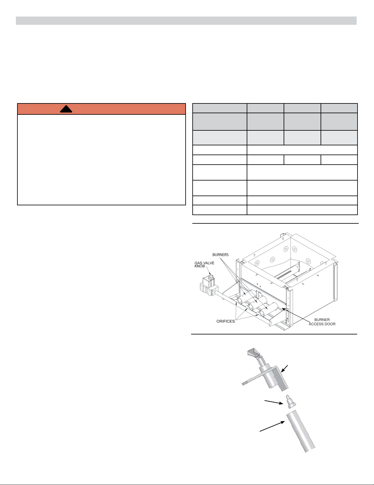
Figure 1 - Burners Assembly
Converting Boiler From Natural Gas To Propane (LP):
1.
Follow instruction TO TURN OFF GAS TO APPLIANCE.
Verify electrical power is OFF.
2.
Remove front panel.
3.
Remove burner access door.
4.
Remove main gas burner tubes. See Figure 1.
5.
Remove main burner orifi ces. See Figure 1.
6.
Install LP gas main burner orifi ces. Discard excess LP
orifi ces.
7.
Use 7/16” wrench, disconnect pilot tube from pilot. See
Figure 2
8.
Remove pilot orifi ce.
9.
Install LP gas pilot orifi ce.
10.
Apply liquid sealing compound (provided) to threads of
pilot assembly fi tting.
11.
Reattach pilot tube to pilot and securely tighten. See
Figure 2.
12.
Replace main gas burner tubes.
.
Figure 2 - Pilot Assembly
Pilot
Pilot Orifi ce
Pilot Tube
P/N 240009725, Rev. C [10/2012]
NATURAL GAS TO LP CONVERSION INSTRUCTIONS
13.
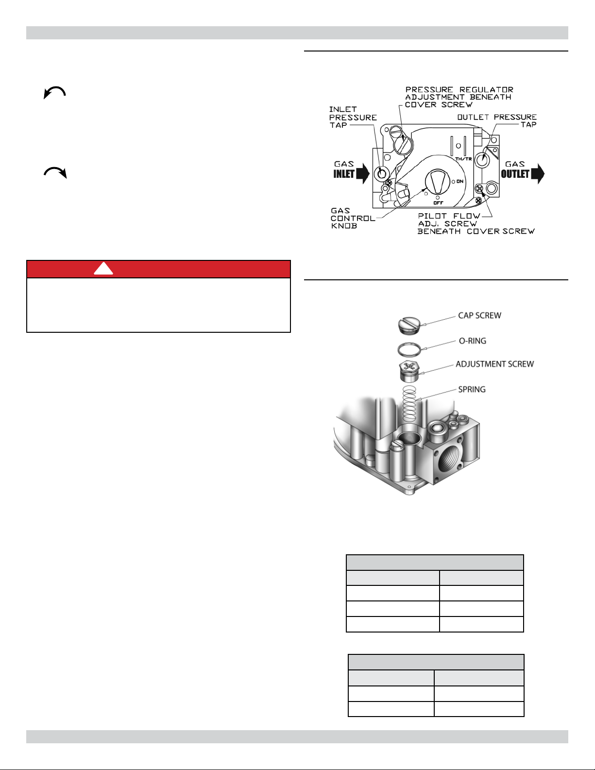
Remove cover screw from gas valve pressure regulator.
See Figure 3.
14.
Remove adjustment screw by turning counterclockwise
. See Figure 4.
15.
Remove stainless steel natural gas spring.
16.
Insert Red LP gas spring.
17.
Install new adjustment screw. Assure screw top is fl ush
with regulator top.
18.
Turn pressure regulator adjustment screw clockwise
eleven (11) complete turns. (This is starting point
for manifold pressure.)
19.
Install manometer to pressure tap on outlet side of gas
valve. See Figure 3.
NOTE: Gas inlet pressure should be between minimum
of 11” w.c. and maximum of 14” w.c.
20.
Turn electric and gas supply ON.
!
DANGER
Fire Hazard. Do not use matches, candles, open
fl ames, or other methods providing ignition source.
Failure to comply will result in death or serious
injury.
Figure 3 - Gas Valve
Figure 4 - Gas Valve Adjustment Screw
Assembly
21.
Check for gas leaks around all gas connections using
commercially available soap solution specifi cally made
for leak detection.
22.
While boiler is running adjust manifold pressure to 11”
water column by turning pressure regulator adjustment
screw. Check for CO2 and CO levels to assure proper
operation.
23.
Turn electric and gas supply OFF.
24.
Remove manometer. Replace pressure tap cover screw
securely.
25.
Install Black LP gas regulator adjustment cover screw
with o-ring. See Figure 4.
26.
Mount conversion label on gas valve (found in spring
kit).
27.
Turn electric and gas supply ON.
28.
Cycle boiler to ensure proper operation and lighting.
29.
Replace front panel.
NOTE: Complete following steps to provide proper
identifi cation for customer service or technical support
issues.
30.
Copy serial number from old rating plate to new one.
31.
Mount new rating plate adjacent to old one.
TABLE 1 - Main Burner Orifi ces
Boiler Size Orifi ce
50, 100, 150, 200 47
125, 170 49
75 50
Parts for steps 16, 17, 25, and 26 are located in
Honeywell LP gas conversion kit HW#393691 (ECR #
1272030) for VR8204, and VR8304 gas valves.
2
TABLE 2 - Propane (LP) Orifi ces
Manufacturer
ECR PB00208
Honeywell 390686-36
Part Number
 Loading...