

Dunkirk DPFO-3T, DPFO-4T, DPFO-9T, DPFO-5T, DPFO-3 Installation Manual And Operating Instructions
...
EV SERIES CAST IRON PRESSURE-FIRED
WET BASE HOT WATER BOILERS
DUNKIRK BOILERS
85 Middle Rd.
Dunkirk, NY 14048
www. ecrinternationaL com
P/N# 14683010, Rev. 3.1 [09/05] • Printed in USA. Made In USA
Boiler Ratings and Capacities ............................. 4
Rules for Safe Installation and Operation ............ 8
Indoor Boiler Installation .................................... 10
Jacket Assembly (Indoor Boilers) ...................... 11
System Piping (Indoor Boilers) .......................... 12
Weatherproof (Outdoor) Boiler Installation ........ 23
Normal Sequence of Operation ......................... 30
Lighting Instructions for Gas Burners ................ 30
Typical Vent Safety Switch Installation .............. 32
Maintenance ...................................................... 34
Service Hints and Troubleshooting .................... 36
Repair Parts ...................................................... 37
KEEP THIS MANUAL NEAR BOILER
BETA!N EOB EUTUBE BBEEBENCE J
The following defined symbols are used throughout
this manual to notify the reader of potential hazards
of varying risk levels.
ndJcates a potential hazardous situation J
hJch, if not avoided, MAY result in minor orJ
oderate injury. It may also be used to alert J
gainst unsafe practices. 3
cMoPORTANT: Read the following instructions'%}
MPLETELY before insta!!ingH j
/9""ii7", '
',4:dy,,
C.S.A. Certified
For Natural Gas Or Propane
¢@@
Tested For 100 LBS
ASME
Working Pressure

FIG, 1 - INDOOR BOILER DIMENSIONS
L
i 0
REA_
±
81DE 5_OE
INDOOR OIL-FIRED HOT WATER BOILERS
62 54 87.6 88.40
DPFO-3T 129 I12 82.9 83.77 I1"
80 70 87.5 88.35
DPFO-4T 14_A''
169 I47 83.3 84.24
99 86 87.5 88.31
DPFO-5T 17½"
208 I82 83.8 84.72
117 I02 87.5 88.26
DPFO-7T 24"
250 217 84.3 85.20
154 134 87.4 88.15
DPFO-9T 30½"
324 282 __5) __(5)
DPFO-3 .45 56 48 87.5 88.22 5" I1"
.90 105 91 82.8 83.19
DPFO-4 1.605 74 64 87.5 88.23
159 I38 83.3 83.91 6" 14_A"
DPFO-5 I!#0 93 81 87.5 88.23 6" 17½"
199 I73 83.9 84.63
DPFO-7 1.05 130 I13 87.6 88.24 7" 24"
2.35 276 240 __(5) __(5)
1.35 167 I46 87.6 88.26
DPFO-9 3.00 353 307 __(5) __(5) 8" 30½"
Firing rates of 2.00 gph or less use a Beckett Model AFG oil burner Firing rates over 2.00 gph use a Beckett Model CF375 oil burner. Optional Riello 40 Series
oil burners also available.
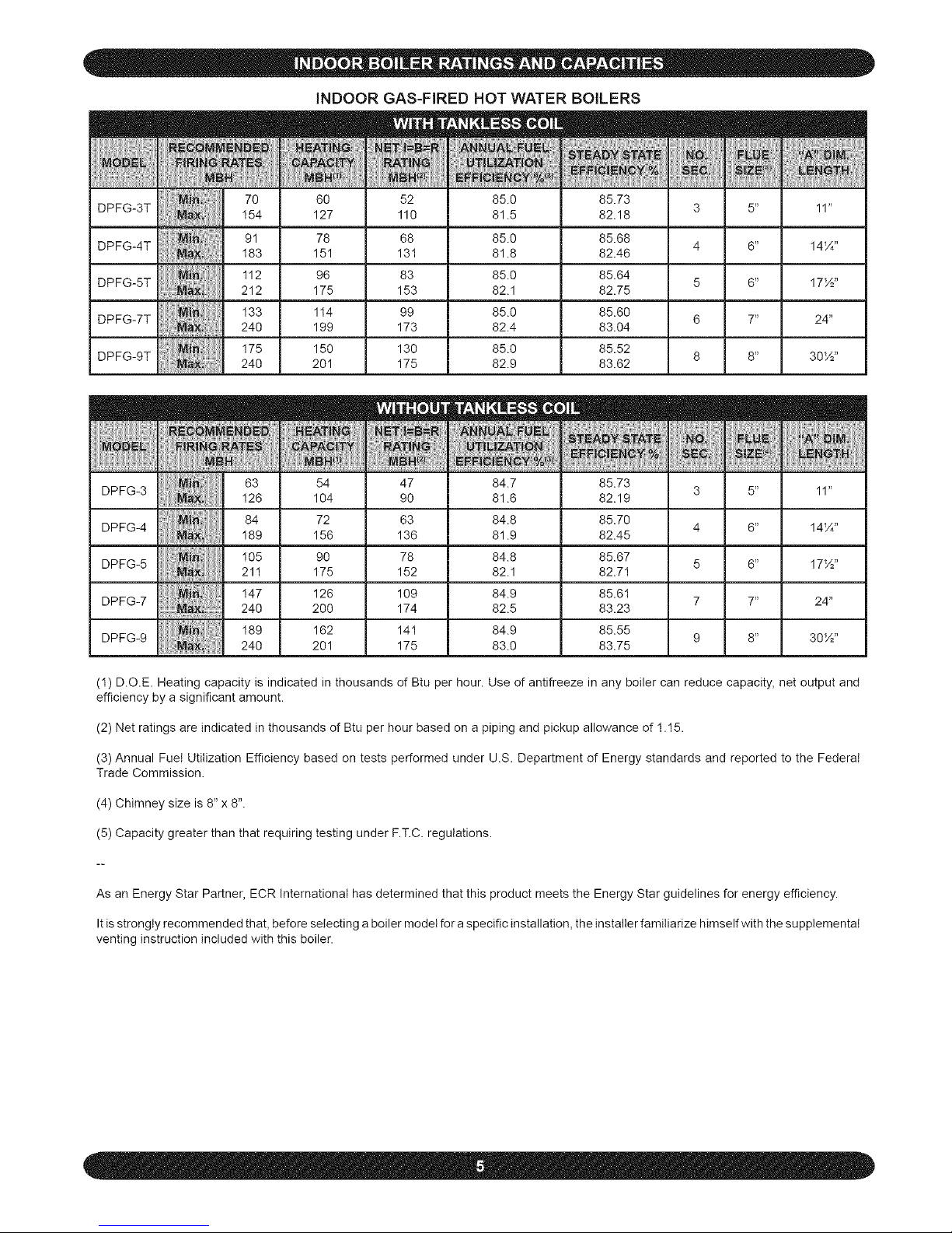
iNDOOR GAS-FIRED HOT WATER BOILERS
70 60 52 85.0 85.73
DPFG-3T 11"
I54 127 110 81.5 82.18
91 78 68 85.0 85.68
DPFG-4T 14¼"
I83 151 131 81.8 82.46
I12 96 83 85.0 85.64
DPFG-5T 17½"
212 175 153 82.1 82.75
I33 114 99 85.0 85.60
DPFG-7T 24"
240 199 173 82.4 83.04
I75 150 130 85.0 85.52
DPFG-9T 30½"
240 201 175 82.9 83.62
63 54 47 84.7 85.73
DPFG-3 3 5" 11"
I26 104 90 81.6 82.19
84 72 63 84.8 85.70
DPFG-4 4 6" 14¼"
I89 156 136 81.9 82.45
105 90 78 84.8 85.67
DPFG-5 5 6" 17½"
211 175 152 82.1 82.7I
I47 128 109 84.9 85.61
DPFG-7 240 200 174 82.5 83.23 7 7" 24"
189 162 141 84.9 85.55
DPFG-9 9 8" 30½"
240 201 175 83.0 83.75
(1) D.O.E. Heating capacity is indicated in thousands of Btu per hour. Use of antifreeze in any boiler can reduce capacity, net output and
efficiency by a significant amount.
(2) Net ratings are indicated in thousands of Btu per hour based on a piping and pickup allowance of 1.15.
(3) Annual Fuel Utilization Efficiency based on tests performed under U.S. Department of Energy standards and reported to the Federal
Trade Commission.
(4) Chimney size is 8" x 8".
(5) Capacity greater than that requiring testing under F.T.C. regulations.
As an Energy Star Partner, ECR International has determined that this product meets the Energy Star guidelines for energy efficiency.
Itis strongly recommended that, before selecting a boiler model for a specific installation, the installer familiarize himself with the supplemental
venting instruction included with this boiler.
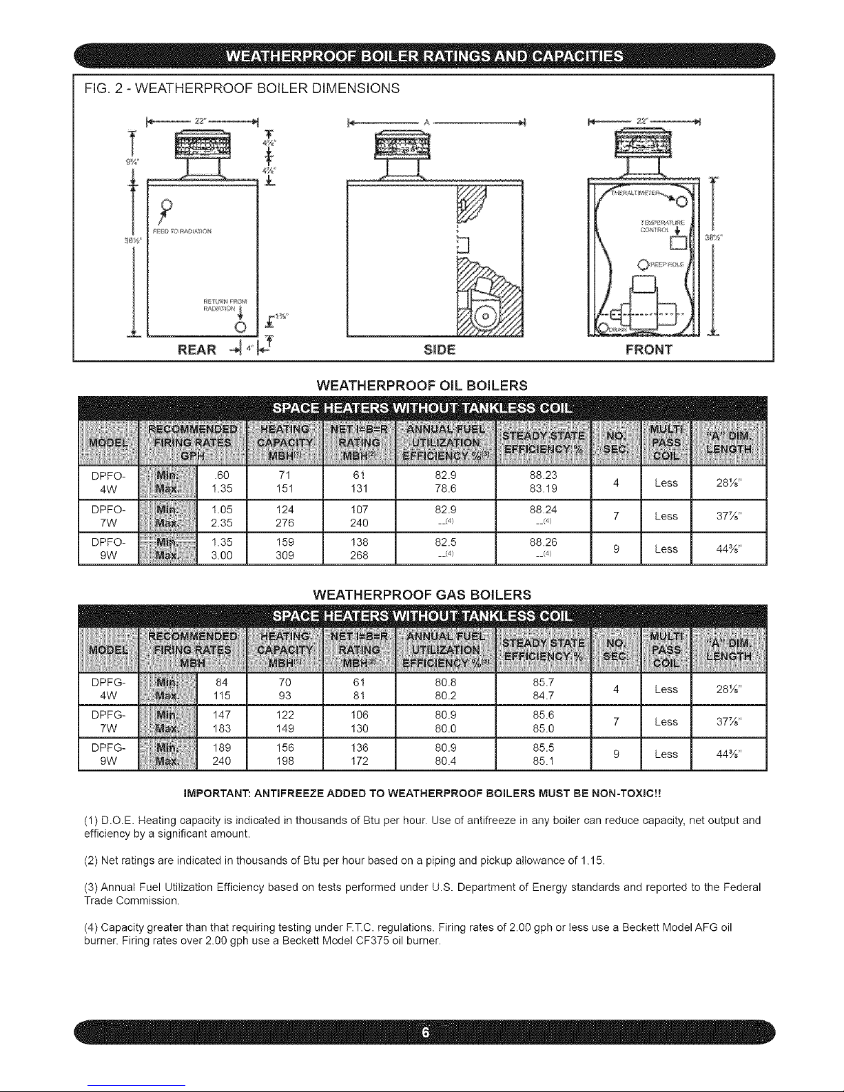
FIG, 2 - WEATHERPROOF BOILER DIMENSIONS
T
t
L
2Z_
?
REAR _ _'_
SIDE FRONT
T
38Y_
l
DPFO-
4W
DPFO-
7W
DPFO-
9W
DPFG-
4W
WEATHERPROOF OIL BOILERS
.60 71 61 82.9 88.23
1.35 I51 I31 78.6 83.19
1.05 I24 I07 82.9 88.24
2.35 276 240 __(4) __<4)
1.35 159 138 82.5 88.26
3.00 309 268 __(4) __<4)
m
NO.
_EC.
4
7
9
DPFG-
7W
DPFG-
9W
WEATHERPROOF GAS BOILERS
70 61 80.8 85.7
93 81 80.2 84.7
I22 I06 80.9 85.6
I49 I30 80.0 85.0
I56 I36 80.9 85.5
I98 I72 80.4 85.1
m
NO,
4
7
9
m
'MULTI:
PASS1
,6:O1_i
Less
Less
Less
28½"
37½"
44%"
iMPORTANT: ANTIFREEZE ADDED TO WEATHERPROOF BOILERS MUST BE NON-TOXIC!!
(1) D.O.E Heating capacity is indicated in thousands of Btu per hour. Use of antifreeze in any boiler can reduce capacity, net output and
efficiency by a significant amount.
(2) Net ratings are indicated in thousands of Btu per hour based on a piping and pickup allowance of 1.15.
(3) Annual Fuel Utilization Efficiency based on tests performed under U.S. Department of Energy standards and reported to the Federal
Trade Commission.
(4) Capacity greater than that requiring testing under F.T.C. regulations. Firing rates of 2.00 gph or tess use a Beckett Model AFG oil
burner. Firing rates over 2.00 gph use a Beckett Model CF375 oil burner.
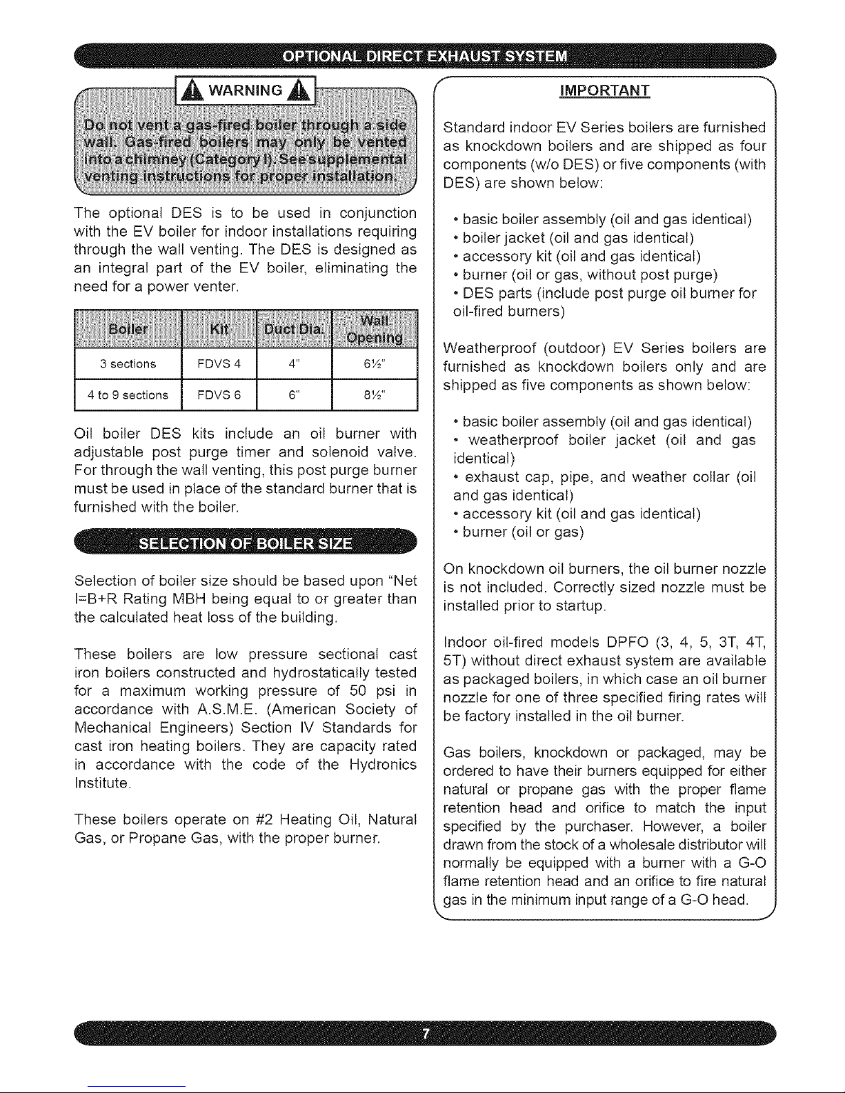
The optional DES is to be used in conjunction
with the EV boiler for indoor installations requiring
through the wall venting, The DES is designed as
an integral part of the EV boiler, eliminating the
need for a power venter.
_iiiiii_iii_i_iiiIHi_iiiiiijiiii_i_iiii_i1iii_i_iiiIiii_iiiiit_iiiiii_i_iiii_i_i_iii!iiI_i_!iiii!!iiii1iii
3 sections FDVS 4 4" 6W'
4 to 9 sections FDVS 6 6" 8½"
Oil boiler DES kits include an oil burner with
adjustable post purge timer and solenoid valve.
For through the wall venting, this post purge burner
must be used in place of the standard burner that is
furnished with the boiler.
Selection of boiler size should be based upon "Net
I=B+R Rating MBH being equal to or greater than
the calculated heat loss of the building.
These boilers are low pressure sectional cast
iron boilers constructed and hydrostatically tested
for a maximum working pressure of 50 psi in
accordance with A.S.M.E. (American Society of
Mechanical Engineers) Section IV Standards for
cast iron heating boilers. They are capacity rated
in accordance with the code of the Hydronics
Institute.
These boilers operate on #2 Heating Oil, Natural
Gas, or Propane Gas, with the proper burner.
IMPORTANT
Standard indoor EV Series boilers are furnished
as knockdown boilers and are shipped as four
components (w/o DES) or five components (with
DES) are shown below:
• basic boiler assembly (oil and gas identical)
• boiler jacket (oil and gas identical)
• accessory kit (oil and gas identical)
• burner (oil or gas, without post purge)
• DES parts (include post purge oil burner for
oil-fired burners)
Weatherproof (outdoor) EV Series boilers are
furnished as knockdown boilers only and are
shipped as five components as shown below:
• basic boiler assembly (oil and gas identical)
• weatherproof boiler jacket (oil and gas
identical)
• exhaust cap, pipe, and weather collar (oil
and gas identical)
• accessory kit (oil and gas identical)
• burner (oil or gas)
On knockdown oil burners, the oil burner nozzle
is not included. Correctly sized nozzle must be
installed prior to startup.
Indoor oil-fired models DPFO (3, 4, 5, 3T, 4T,
5T) without direct exhaust system are available
as packaged boilers, in which case an oil burner
nozzle for one of three specified firing rates wilt
be factory installed in the oil burner.
Gas boilers, knockdown or packaged, may be
ordered to have their burners equipped for either
natural or propane gas with the proper flame
retention head and orifice to match the input
specified by the purchaser. However, a boiler
drawn from the stock of a wholesale distributor will
normally be equipped with a burner with a G-O
flame retention head and an orifice to fire natural
as in the minimum input range of a G-O head.
,J
• Read the installation manual before beginning
the installation. Failure to follow the rules for
safe operation and the instructions can cause a
malfunction of the boiler and result, serious bodily
injury, and/or property damage.
• Check your local codes and utility requirements
before installation. The installation must be in
accordance with their directives, or, in their absence,
follow NFPA Installation Codes and good industry
practice.
• Before servicing, allow boiler to coot. Always shut
off any electricity and oil to boiler when working on
it. This will prevent any electrical shocks or burns.
• Inspect oil lines and connections for leaks.
• Be certain oil burner nozzle or gas orifice is size
required. Over-firing will result in early failure of
the boiler sections. This will cause dangerous
operation.
• Never vent this boiler into an enclosed space.
Always vent to the outside. Never vent to another
room or inside a building.
• Be sure there is adequate air supply for complete
combustion.
• Follow a regular service and maintenance
schedule for efficient and safe operation.
• Keep boiler area clean and free of combustible
material, gasoline, and other flammable vapors
and liquids.
• Proper through-the-walt venting requires use of
complete DES (oil-fired units only).
• Oil and gas burners are not do-it-yourself items.
This boiler must be installed and serviced by
qualified professionals using combustion test
instruments.
• Be aware when piping the relief valve if the
system pressure exceeds the safe limit of 30 Ibs.
per square inch, the relief valve will automatically
open. Lifting of the relief valve can discharge large
quantities of steam and hot water, which may
damage the surroundings. Before installing the
relief valve, read the manufacturer's instructions
and the maintenance section of the manual on
relief valves.
• Frequent and mysterious lifting of the relief valve
may be a sign of an improperly sized expansion
tank. Installation and sizing of the expansion tank
must consider the heating system's total water
volume, temperature, boiler initial fill pressure, and
system arrangement. For proper installation and
maintenance follow the guidelines established by
ECR and the manufacturer.
• Expansion tank performance and life expectancy
can be hindered by overfilling the boiler. ECR
recommends an initial fill pressure of 10 - 12 psig.
For higher fill pressures, the expansion tank's air
charge will need to match the fill pressure. Consult
the manufacturer's guidelines for sizing and
selection.
• Purging the heating system of air and gases
during the boiler's initial commissioning is critical
for proper circulation and quiet performance. Once
the air and gases are purged, for boiler installations
using float type vents, the air vents should be closed
for normal operation. If air is heard or noticed by a
loss of heat, purge the system and open the vents
for a short period of time.
- iAc o ,o.Ai
This boiler has been designed for residential
installations. If used for commercial applications,
all jurisdictional requirements must be met. This
may require wiring and/or piping modifications.
The manufacturer is not responsible for any
changes to the original design.
DO NOT USE GASOLINE CRANKCASE
DRAININGS OR ANY OIL CONTAINING
k..GASOLINE"
Check to be sure you have the right size boiler
before starting the installation. See rating and
capacity tables on preceding pages. Check the
rating plate on the right side of the boiler.
You must see that the boiler is supplied with the
proper fuel, fresh air for combustion, and a suitable
electrical supply. Also, the boiler must be connected
to a suitable venting system and an adequate piping
system. Finally, a thermostat, properly located, is
needed for control of the heating system. If you
have any doubts as to the various requirements,
check with local authorities and obtain professional
help where needed.
These installation instructions are vital to the proper
and safe operation of the heating system. Take the
time to be sure they are carefully followed.
lways keep the manual fuel supply valve shut I
if the burner is shut down for an extended r
eriod of time. J
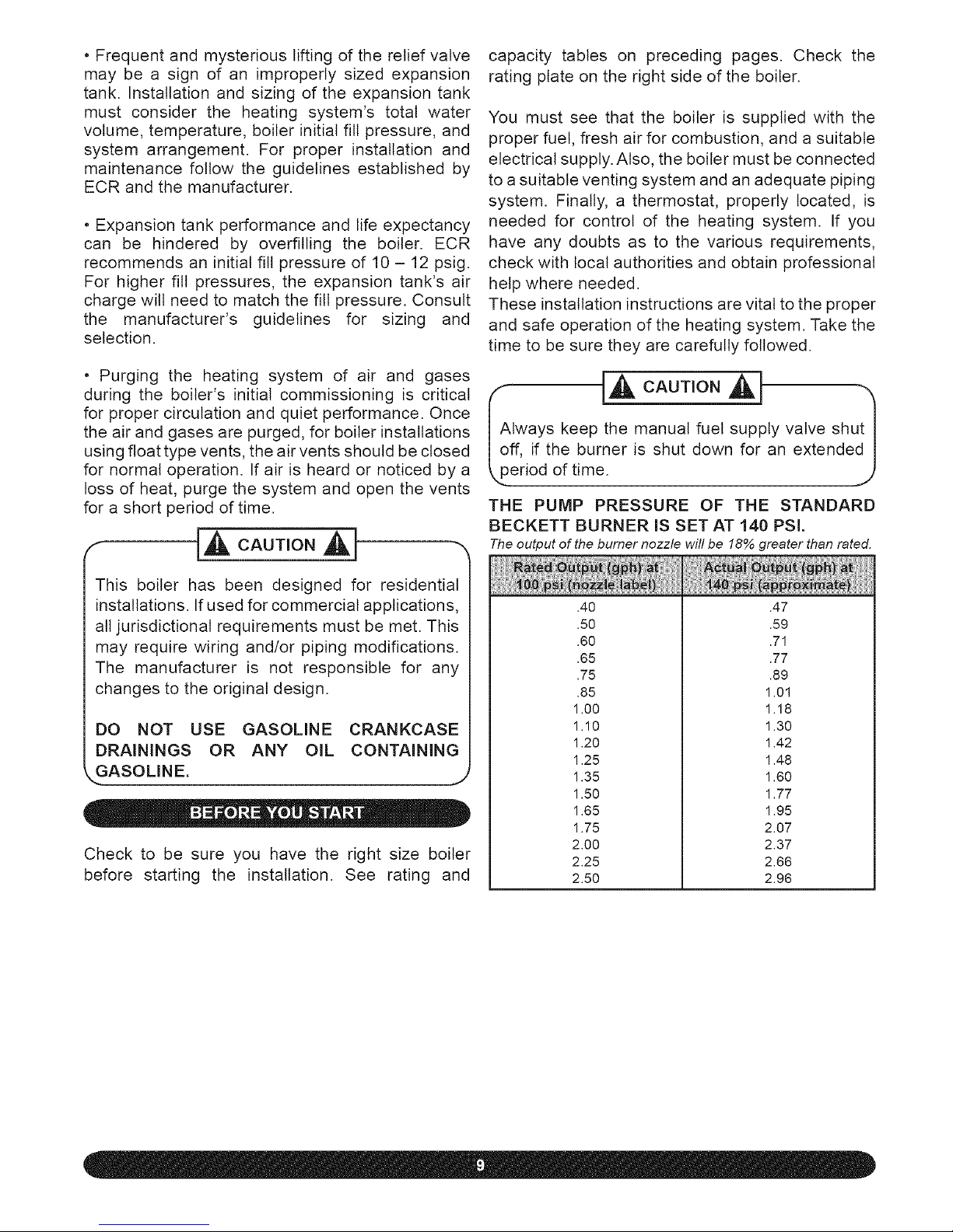
THE PUMP PRESSURE OF THE STANDARD
BECKETT BURNER IS SET AT 140 PSI.
The output of the burner nozzle will be 18% greater than rated.
.40
.50
.60
.65
.75
.85
1.00
1.10
1.20
1.25
1.35
1.50
1.65
1.75
2.00
2.25
2.50
.47
.59
.71
.77
.89
1.01
1.18
1.30
1.42
1.48
1.60
1.77
1.95
2.07
2.37
2.66
2.96
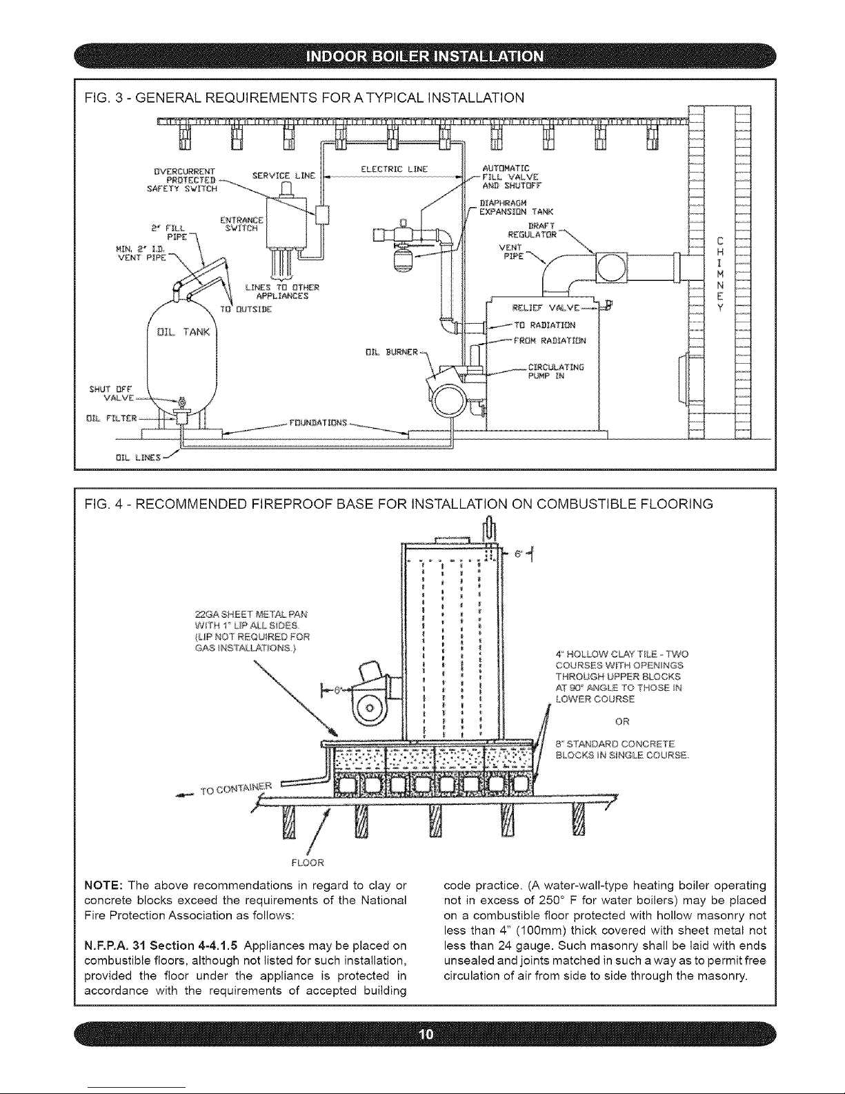
FIG. 3 - GENERAL REQUIREMENTS FOR ATYPICAL INSTALLATION
k.....
FIG. 4 - RECOMMENDED FIREPROOF BASE FOR INSTALLATION ON COMBUSTIBLE FLOORING
2"2GASHBET METAL PAN
WTH I LIPAU.SiDES
(LIP NOT R_QU_R_D POR
GAS _NS_ALL#_I"ONS )
|
4" HOLLOW C_<f T_LE _ TWO
COURSES WTH OPENINGS
THROUGH 8PPER BLOCKS
AT 9Q _ ANGLE TO THOS_ IN
LOW£R COURS_
OR
8" BTANDAR@ C©NCRET_
BLOCKS N B_NGLE COURSE
/
FLOOR
NOTE: The above recommendations in regard to clay or
concrete blocks exceed the requirements of the National
Fire Protection Association as follows:
N.F.RA. 31 Section 4-4.1.5 Appliances may be placed on
combustible floors, although not listed for such installation,
provided the floor under the appliance is protected in
accordance with the requirements of accepted building
code practice. (A water-wall-type heating boiler operating
not in excess of 250 ° F for water boilers) may be placed
on a combustible floor protected with hollow masonry not
less than 4" (100mm) thick covered with sheet metal not
less than 24 gauge. Such masonry shall be laid with ends
unsealed and joints matched in such a way as to permit free
circulation of air from side to side through the masonry.
ote:PleaseseetheseparateVentingInstructionforflue%I
zelimitationandotherinformationonventing.FordirectI
xhaustsystems,thetotalrunofhorizontalfluepipemustJ
otexceed6'andthetotalrunofverticalfluepipemustnotJ
xceed10'(oil-firedunitsonly), j
1. Place boiler at a location as centralized to the
piping system and as close to the chimney or vent
terminal as possible to minimize condensation. At
input rates up to 1.75 gph (245,000 Btu/hr), the
supply and return from radiation may be piped on
the same end of the boiler. At higher rates, it is
recommended that the supply be piped from the
rear of the boiler and the return be piped from the
front of the boiler. Coordinate jacket installation
with piping. See "Jacket Assembly Instructions"
and "Piping Diagrams" in this manual for more
information.
2. See Figure 4 for installation on combustible
flooring. If necessary, place metal shims beneath
feet to ensure a level unit.
3. Accessibility clearances must take precedence
over fire protection clearances. Allow at least 24"
for servicing at the tankless and burner sides of the
unit. Allow at least 18" at a side where passage is
required for access to another side for servicing.
A 6" clearance from combustible material on all
sides and the top is recommended. 18" clearance
is necessary between smoke pipe and nearest
combustible material. See NFPA 31, latest revision,
for safe methods to reduce clearances where
necessary. NFPA publications are available at
Battery Park, Quincy, MA 02269.
CONSULT FIRE AUTHORITIES
J
FOR LOCAL REQUIREMENTS
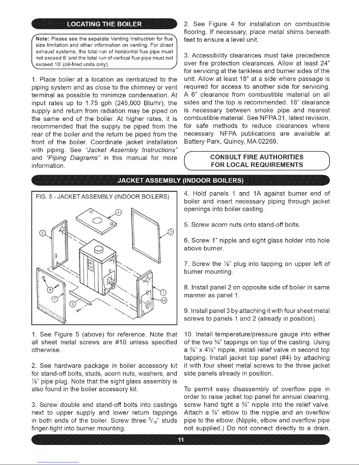
FIG. 5 - JACKETASSEMBLY (INDOOR BOILERS)
4. Hold panels 1 and 1A against burner end of
boiler and insert necessary piping through jacket
openings into boiler casting.
5. Screw acorn nuts onto stand-off bolts.
6. Screw 1" nipple and sight glass holder into hole
above burner.
7. Screw the ½" plug into tapping on upper left of
burner mounting.
8. Install panel 2 on opposite side of boiler in same
manner as panel 1.
9. Install panel 3 by attaching it with four sheet metal
screws to panels 1 and 2 (already in position).
1. See Figure 5 (above) for reference. Note that
all sheet metal screws are #10 unless specified
otherwise.
2. See hardware package in boiler accessory kit
for stand-off bolts, studs, acorn nuts, washers, and
½" pipe plug. Note that the sight glass assembly is
also found in the boiler accessory kit.
3. Screw double end stand-off bolts into castings
next to upper supply and lower return tappings
in both ends of the boiler. Screw three Sll?' studs
finger-tight into burner mounting.
10. Install temperature/pressure gauge into either
of the two 3A" tappings on top of the casting. Using
a 3A"x 4½" nipple, install relief valve in second top
tapping. Install jacket top panel (#4) by attaching
it with four sheet metal screws to the three jacket
side panels already in position.
To permit easy disassembly of overflow pipe in
order to raise jacket top panel for annual cleaning,
screw hand tight a 3A" nipple into the relief valve.
Attach a 3A" elbow to the nipple and an overflow
pipe to the elbow. (Nipple, elbow and overflow pipe
not supplied.) Do not connect directly to a drain,
butleaveanair gap.Noshutoffof anydescription
shallbeplacedbetweenthe safetyreliefvalveand
the boiler, or on dischargepipes betweensuch
safetyvalvesand the atmosphere.Installationof
the safetyreliefvalve shallconformto the ANSI/
ASMEBoilerand PressureVesselCode,Section
IV.The manufactureris not responsiblefor any
waterdamage.
Ifpreferred,oneof thetop tappingsmaybe used
foran airventandthe reliefvalvemaybeinstalled
in an upper 1½"side tappingof the castingwith
a bushing,nipple,andstreetelbow.Valvespindle
mustbevertical.
11.Installangleiron(#5)openedgeup to panels
1 and 2 on the remainingexposedside of the
boilernearfloor level.Angleiron is attachedwith
twosheetmetalscrewsto theinsideof theturned
edgesofpanels1and2.
12. Install knobs (#6) on door panel (#7) using #8
machine screws. Install door panel by resting lower
edge inside angle iron (#5) and snapping top sides
into place.
1. Antifreeze added to boilers must be non-toxic,
and must of a type specifically intended for use
in closed hydronic heating systems. Under no
circumstances should automotive antifreeze be
used.
2. Use of antifreeze in any boiler may reduce
capacity by 10% or more and increase fuel
consumption. Tanktess coil performance will fall as
concentration of antifreeze is increased. See below
for water volumes of boilers and piping.
3. Because antifreeze forms slush rather than hard
ice, it is safe to protect only to 10 degrees above
coldest temperature anticipated provided slush
formed can move towards expansion tank.
BOILER WATER VOLUMES
DPF-3 7 DPF-3T 10
DPF-4 9 DPF-4T 12
DPF-5 11 DPF-5T 14
DPF-7 15 DPF-6T 16
DPF-9 19 DPF-8T 20
PiPiNG WATER VOLUMES
Divide total length of piping in feet by appropriate factor
below to determine volume in gallons.
½" 82.5 63.5
¾" 40.0 36.0
1" 23.3 22.2
1%" 15.3 12.8
1½" 10.8 9.5
2" 6.2 5.8
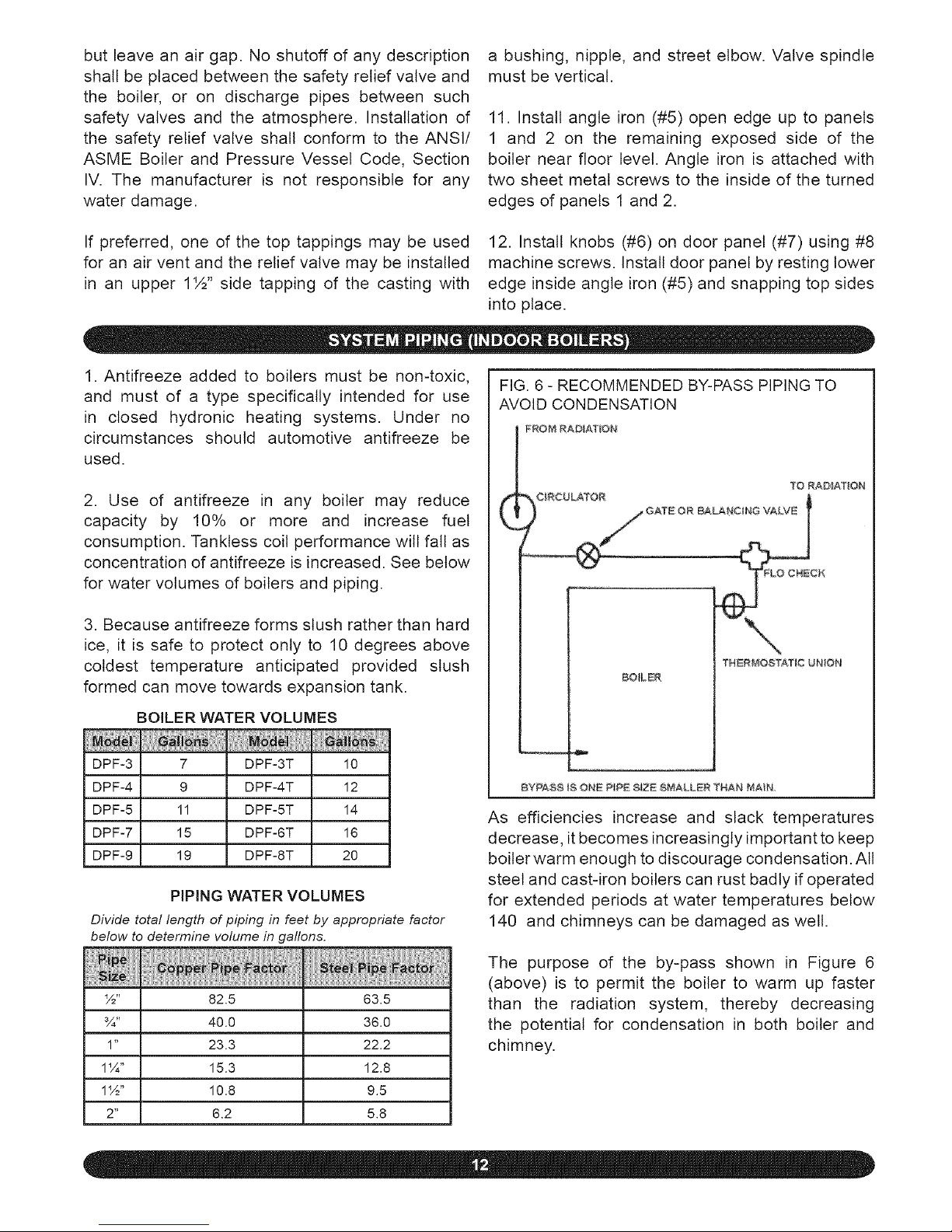
FIG. 6 - RECOMMENDED BY-PASS PIPING TO
AVOID CONDENSATION
FROM RADiATiON
(
?O RADIATION
TNERMOSTA, T_C UNION
BO_LER
BYPA@8 IS ONE P_PE @IZE @_IALLER THAN MA_N
As efficiencies increase and slack temperatures
decrease, it becomes increasingly important to keep
boiler warm enough to discourage condensation. All
steel and cast-iron boilers can rust badly if operated
for extended periods at water temperatures below
140 and chimneys can be damaged as well.
The purpose of the by-pass shown in Figure 6
(above) is to permit the boiler to warm up faster
than the radiation system, thereby decreasing
the potential for condensation in both boiler and
chimney.
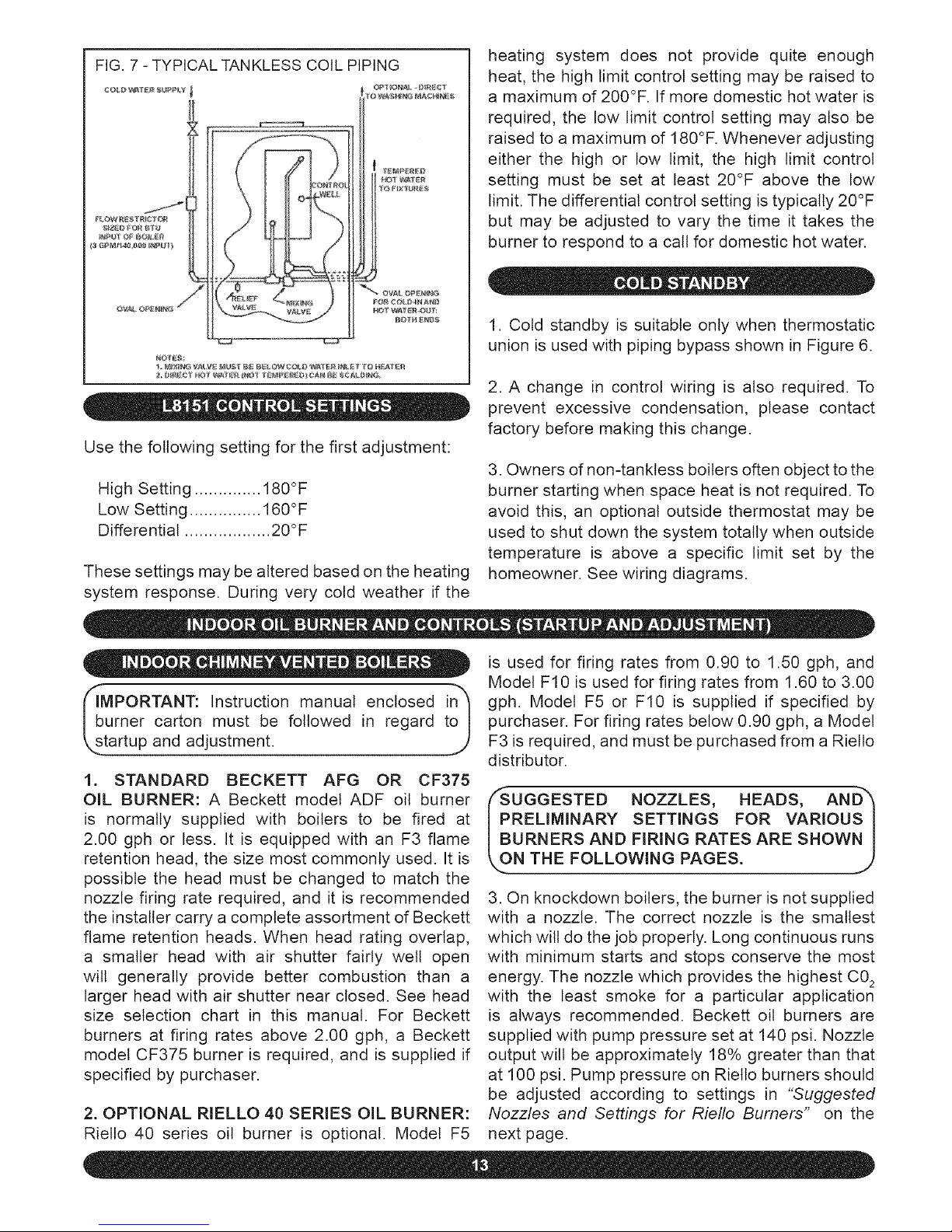
FIG.7-TYPICALTANKLESSCOILPIPING
II
Use the following setting for the first adjustment:
High Setting .............. 180°F
Low Setting ............... 160°F
Differential .................. 20°F
These settings may be altered based on the heating
system response. During very cold weather if the
heating system does not provide quite enough
heat, the high limit control setting may be raised to
a maximum of 200°F. If more domestic hot water is
required, the low limit control setting may also be
raised to a maximum of 180°F. Whenever adjusting
either the high or low limit, the high limit control
setting must be set at least 20°F above the low
limit. The differential control setting is typically 20°F
but may be adjusted to vary the time it takes the
burner to respond to a call for domestic hot water.
1. Cold standby is suitable only when thermostatic
union is used with piping bypass shown in Figure 6.
2. A change in control wiring is also required. To
prevent excessive condensation, please contact
factory before making this change.
3. Owners of non-tanktess boilers often object to the
burner starting when space heat is not required. To
avoid this, an optional outside thermostat may be
used to shut down the system totally when outside
temperature is above a specific limit set by the
homeowner. See wiring diagrams.
_sb,MPORTANT: Instruction manual enclosed i!_
umer carton must be followed in regard t
tartup and adjustment.
1. STANDARD BECKETT AFG OR CF375
OIL BURNER: A Beckett model ADF oil burner
is normally supplied with boilers to be fired at
2.00 gph or less. It is equipped with an F3 flame
retention head, the size most commonly used. It is
possible the head must be changed to match the
nozzle firing rate required, and it is recommended
the installer carry a complete assortment of Beckett
flame retention heads. When head rating overlap,
a smaller head with air shutter fairly well open
will generally provide better combustion than a
larger head with air shutter near closed. See head
size selection chart in this manual. For Beckett
burners at firing rates above 2.00 gph, a Beckett
model CF375 burner is required, and is supplied if
specified by purchaser.
2. OPTIONAL RIELLO 40 SERIES OIL BURNER:
Riello 40 series oil burner is optional. Model F5
is used for firing rates from 0.90 to 1.50 gph, and
Model F10 is used for firing rates from 1.60 to 3.00
gph. Model F5 or F10 is supplied if specified by
purchaser. For firing rates below 0.90 gph, a Model
F3 is required, and must be purchased from a Rietto
distributor.
/'-SUGGESTED NOZZLES, HEADS, AN D"_
PRELIMINARY SETTINGS FOR VARIOUS I
BURNERS AND FIRING RATES ARE SHOWN I
,..ON THE FOLLOWING PAGES. J
3. On knockdown boilers, the burner is not supplied
with a nozzle. The correct nozzle is the smallest
which will do the job properly. Long continuous runs
with minimum starts and stops conserve the most
energy. The nozzle which provides the highest C0_
with the least smoke for a particular application
is always recommended. Beckett oil burners are
supplied with pump pressure set at 140 psi. Nozzle
output will be approximately 18% greater than that
at 100 psi. Pump pressure on Rietto burners should
be adjusted according to settings in "Suggested
Nozzles and Settings for Riello Burners" on the
next page.
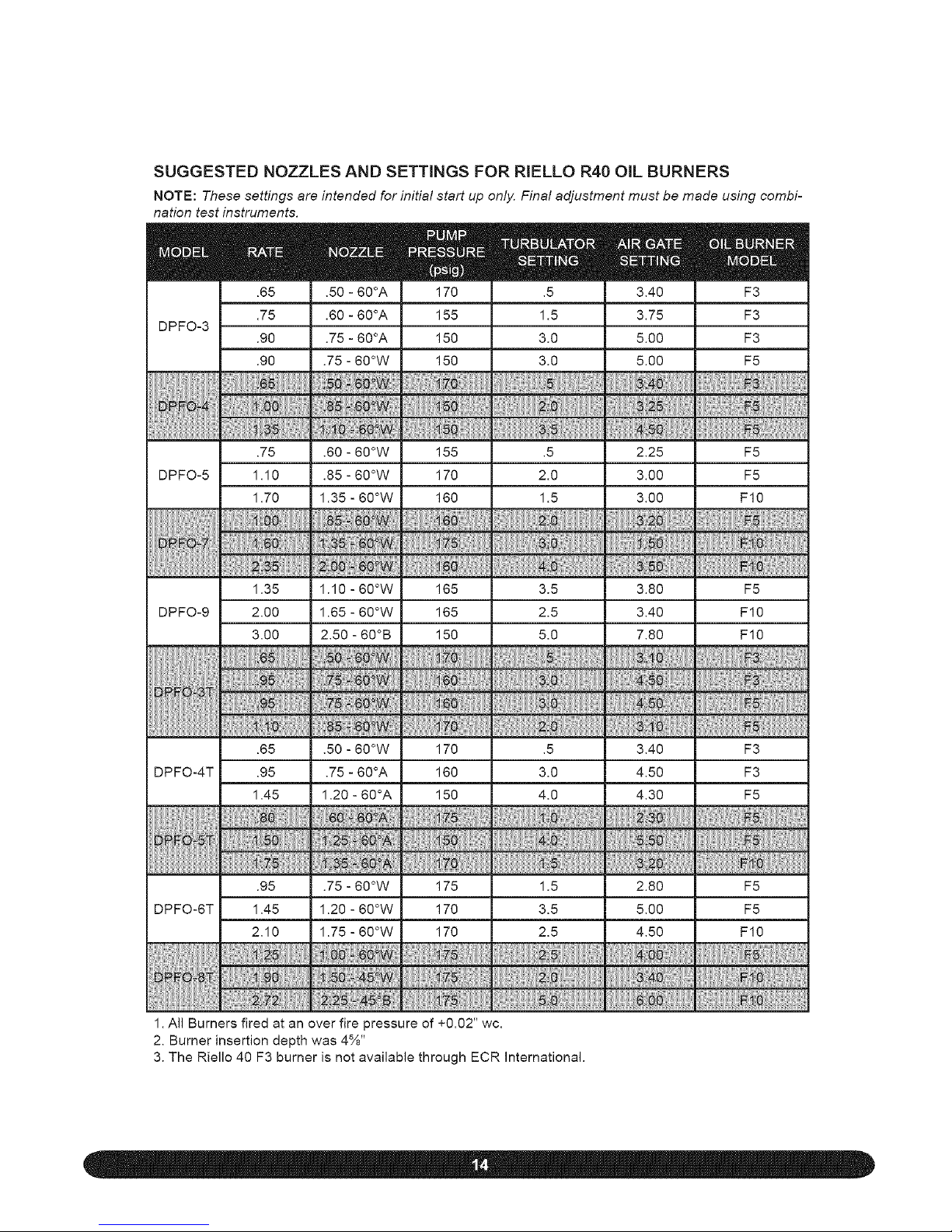
SUGGESTED NOZZLES AND SETTINGS FOR RIELLO R40 ONL BURNERS
NOTE: These settings are intended for initial start up only. Final adjustment must be made using combi-
nation test instruments.
mm
.65
.75
DPFO-3
.90
.90
.75
DPFO-5 1.10
1.70
1.35
DPFO-9 2.00
3.00
.65
DPFO-4T .95
1.45
.95
DPFO-6T 1.45
2.10
m
.50 - 60°A
.60 - 60°A
.75 - 60°A
.75 - 60°W
m
170
155
150
150
m
3.40
3.75
5.00
5.00
m
F3
F3
F3
F5
.60 - 60°W 155 .5 2.25 F5
.85 - 60°W 170 2.0 3.00 F5
1.35 - 60°W 160 1.5 3.00 F10
1.10 - 60°W 165 3.5 3.80 F5
1.65 - 60°W 165 2.5 3.40 F10
2.50 - 60°B 150 5.0 7.80 F10
.50 - 60°W 170 .5 3.40 F3
.75 - 60°A 160 3.0 4.50 F3
1.20 - 60°A 150 4.0 4.30 F5
.75 - 60°W 175 1.5 2.80 F5
1.20 - 60°W 170 3.5 5.00 F5
1.75 - 60°W 170 2.5 4.50 F10
1. All Burners fired at an over fire pressure of +0.02" wc.
2. Burner insertion depth was 4%"
3. The Riello 40 F3 burner is not available through ECR International.
 Loading...