

Dunkirk DKVLT-050, DKVLT-299, DKVLT-075, DKVLT-100, DKVLT-150 Installation, Operation & Maintenance Manual
...
Models
DKVL T-050
DKVL T-075
WALL MOUNTED
DKVL T-100
DKVL T-150
DKVLT-200
DKVL T- 299
GAS BOILER
INSTALLATION, OPERATION &
MAINTENANCE MANUAL
An ISO 9001-2008 Certified Company
050/075/100/150/200
SIZE SHOWN
Manufacturedby:
ECRInternational,Inc.
2201 Dwyer Avenue, Utica NY 13501
web site: www.ecrinternational.com
P/N# 240008888, Rev. J [06/2013]
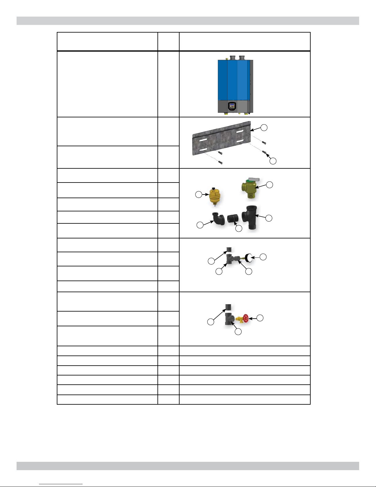
VERIFY CONTENTS RECEIVED
Description
Item
No. Illustration
Fully Assembled Boiler 1
Metal Wall Bracket 2
Lag Bolt, 3/8" x 3" Hex (4 ea) 3
*Safety Relief Valve 4
3/4" Tee 5
3/4" Nipple 6
299 SIZE
SHOWN
2
3
4
8
3/4" x 1/4" Elbow 7
Air Vent 8
7
6
5
**Temperature Pressure Gauge 9
Bushing 3/4" x 1/4" 10
3/4" Tee (Same as No. 11) 11
12
11
9
10
Nipple 1¼ x 5½ 12
Drain Valve, 3/4" 13
3/4" Tee 14
15
14
13
Nipple 1¼ x 5½ 15
Bushing 7/8" OD, Heyco (2 ea) 16
Used for electrical wire knockouts.
Stopper, Rubber 5/16" (2 ea) 17 Used for packaging holes on back of boiler.
Plastic Plug (2 ea) 18 Used for packaging holes on back of boiler.
Outdoor Sensor 19 Used for measuring outside temperature.
Critical Installation Instruction 20
11" x 17" Page for critical installation issues.
Document Package 21 Includes essential documents.
* Boiler provided with 30 psig (206 kpa) safety relief valve. Field source safety relief valve if system pressure
greater than 25 psig.
** Boiler provided with 75 psig temperature pressure gauge. Field source temperature pressure gauge if system
pressure greater than 60 psig.
2
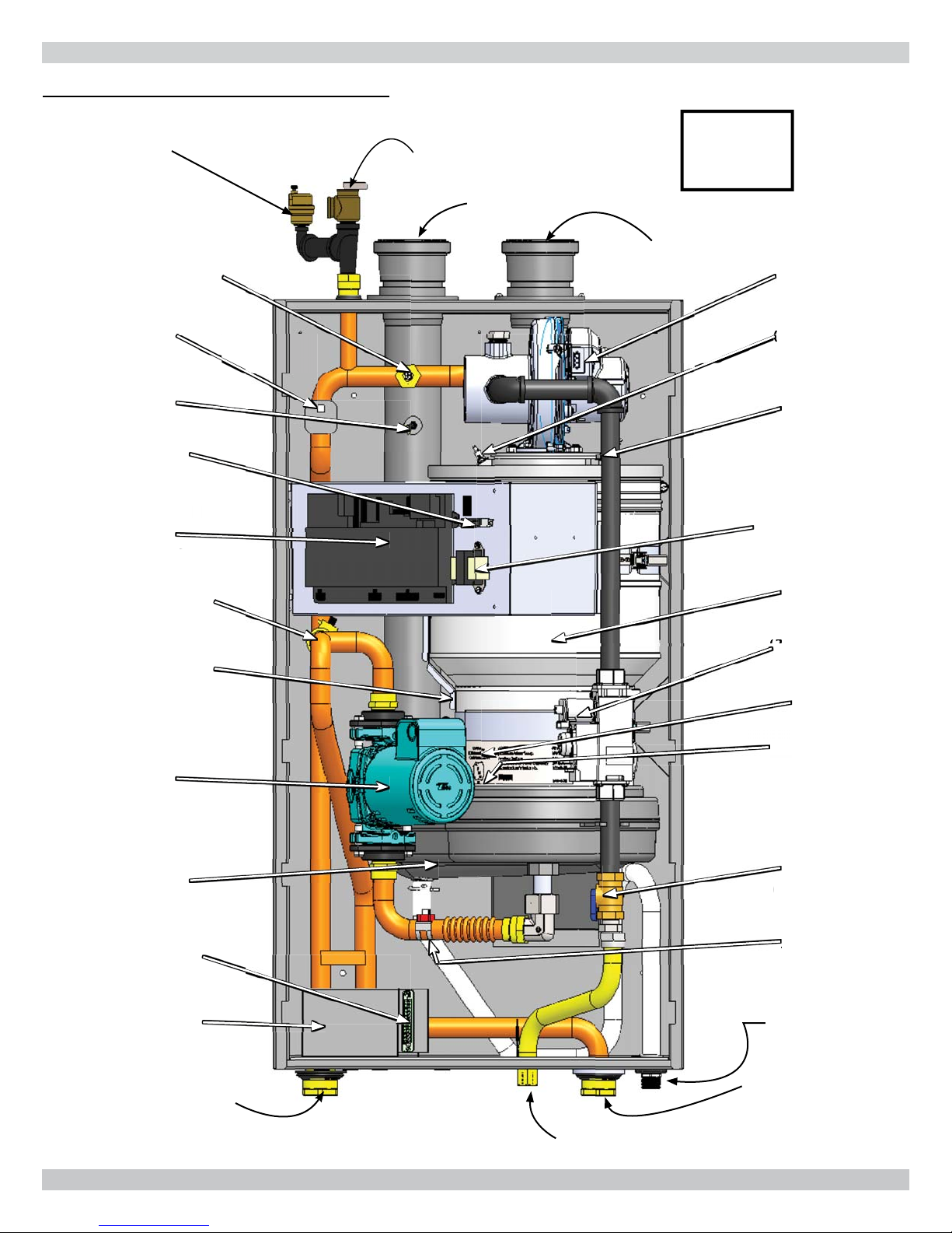
DIMENSIONS
FIGURE 1-1 Dimensions
(D)
Wall Hanging
Bracket
(D)
(E)
DIMENSIONS
Safety Relief
Valve
Connection
(¾ NPT)
Vent Connector
Combustion Air
(A)
(B)
Models
Width (A) 20" (508mm)
Height (B) 30" (762mm)
Depth (C) 14" (356mm)
Bracket (D) 28" (711mm)
Height (E) 31" (787mm)
Water
Connections
Gas
Connection
Condensate Drain
Connection (L)
Weight
Location (G) 2" (51mm) 2" (51mm)
Location (H)
Location (I)
Location (J) 4-1/2" (114mm) 4-1/2" (114mm)
Table 1 : Physical Data
050/075/100 150/200 299
Size(F) 1-1/4" NPT
5" (127mm)
3" (76mm)
Size (K)
Shipping 111 lb (50 kg)
Unit 91 lb (41 kg)
1/2"
NPT
3/4" NPT
23" (584mm)
40" (1041mm)
16.0"
(406mm)
40" (1016mm)
42" (1092mm)
1-1/4" NPT
2" (51mm)
4-½"
(114mm)
3/4"
NPT
3/4" NPT
~182 lb
(83 kg)
~157 lb
(71 kg)
18.3"
(465mm)
~225 lb
(102 kg)
~195 lb
(89 kg)
(G)
Supply Water (F)
Gas Connection (K)
Return Water (F)
(H)
(I)
(J)
(C)
Vent Connector 2" (51mm) 3" (76mm)
Condensate Drain Connection (L)
3

TABLE OF CONTENTS
1 - Introduction ............................................................................................................................... 5
2 - Important Safety Information .................................................................................................... 6
3 - Component Listing .....................................................................................................................7
4 - Locating Boiler .........................................................................................................................11
5 - Hydronic Piping ........................................................................................................................13
5.2 Special Conditions ................................................................................................................. 13
5.3 Safety Relief Valve and Air Vent............................................................................................ 13
5.4 Trim Piping ........................................................................................................................... 14
5.5 System Piping....................................................................................................................... 14
6 - Combustion Air And Vent Piping ...............................................................................................21
6.2 Removal of Existing Boiler From Common Vent System........................................................... 21
6.3 Venting Materials ................................................................................................................. 21
6.4 Vent Pipe Installation ............................................................................................................. 22
6.5 Vent Termination .................................................................................................................. 22
6.6 Venting Confi gurations ........................................................................................................... 23
6.7 Side Venting Terminal Requirements..........................................................................................28
6.8 Multiple Boiler Venting Installation............................................................................................30
6.9 Condensate Piping ................................................................................................................. 31
7 - Gas Supply Piping ....................................................................................................................32
8 - Electrical Connections .............................................................................................................. 34
8.3 Line Voltage Connections ....................................................................................................... 34
8.4 External Connections ............................................................................................................. 34
9 - Start Up Procedure ...................................................................................................................36
9.6 Perform CSD-1 Compliance Test ......................................................................................................40
9.7 Complete Start Up Procedure .................................................................................................. 41
10 - Operating Instructions ........................................................................................................... 42
11 - General Maintenance And Cleaning ........................................................................................ 43
12 - Ratings And Capacities ........................................................................................................... 46
13 - Trouble Shooting ....................................................................................................................47
14 - Wiring Diagram ......................................................................................................................65
15 - Glossary .................................................................................................................................68
Appendix A - Control Module ......................................................................................................... 70
1.1 Introduction ......................................................................................................................... 70
1.2 Operation ............................................................................................................................. 70
1.3 Status Indication ................................................................................................................... 70
1.4 Sequence of Operation ........................................................................................................... 71
1.5 Theory of Operation .............................................................................................................. 73
4

1 - INTRODUCTION
1.1 Designated Use
• Hot water heating boiler.
• Indoor installation.
• Closet or alcove installation.
• Direct vent boiler.
• For use with natural gas or liquefi ed petroleum gases
(LP/propane).
1.2 The unit MUST NOT:
• Directly heat potable water. Indirect heating is acceptable.
• Heat water with non-hydronic heating system chemicals
present (example, swimming pool water).
• Exceed 150 psig (1.03 MPa) maximum allowable
working pressure.
• Exceed 195°F (90.5°C) system design temperature.
1.3 Operational Features
• Modulating: 20-100%.
• Integral Dual Limit.
• Integral Low Water Cutoff (with test button).
• Outdoor Temperature Reset.
• Integral Multiple Boiler Control.
Information and specifi cations outlined in this manual in effect at the
time of printing of this manual. Manufacturer reserves the right to
discontinue, change specifi cations or system design at any time without
notice and without incurring any obligation, whatsoever.
5
!
This is the safety alert symbol. Symbol alerts you to
potential personal injury hazards. Obey all safety messages
following this symbol to avoid possible injury or death.
2.2
Become familiar with symbols identifying
potential hazards.
2 - IMPORTANT SAFETY INFORMATION
2.1 General
Boiler installation shall be completed by qualifi ed agency.
See glossary for additional information.
WARNING
!
Fire, explosion, asphyxiation and electrical shock
hazard. Improper installation could result in death or
serious injury. Read this manual and understand all
requirements before beginning installation.
2.2
Become familiar with symbols identifying
potential hazards.
This is the safety alert symbol. Symbol alerts you to
potential personal injury hazards. Obey all safety messages
following this symbol to avoid possible injury or death.
!
DANGER
Indicates a hazardous situation which, if not avoided,
WILL result in death or serious injury
2.3 Installation shall conform to requirements of
authority having jurisdiction or in absence of such
requirements:
• National Fuel Gas Code, ANSI Z223.1/NFPA 54
• National Electrical Code, NFPA 70.
• Canada
• Natural Gas and Propane Installation Code,
CAN/CSA B149.1.
• Canadian Electrical Code, Part I, Safety Standard
for Electrical Installations, CSA C22.1
2.4 Where required by authority having jurisdiction,
installation shall conform to Standard for Controls
and Safety Devices for Automatically Fired Boilers,
ANSI/ASME CSD-1.
Additional manual reset low water cutoff may be required.
2.5 Requirements for Commonwealth of
Massachusetts:
Boiler installation must conform to Commonwealth of
Massachusetts code 248 CMR which includes but is not
limited to:
Installation by licensed plumber or gas fi tter.
.
!
WARNING
Indicates a hazardous situation which, if not avoided,
could result in death or serious injury.
!
CAUTION
Indicates a hazardous situation which, if not avoided,
could result in minor or moderate injury.
NOTICE
Used to address practices not related to personal
injury.
6

Low Voltage Terminal Strip
Heat Exchanger Pump
Gas Shutoff Valve
Fuel supply isolation during
servicing. See section 7
Combustion Air Blower
Delivers proper quantity of
combustion air, receives fuel from gas valve, mixes air
and fuel sending mixture to burner for combustion.
Gas (Control) Valve
Delivers proper quantity of fuel
to Combustion Air Blower. See section 7.
Supply Water Temperature Sensor and High Limit
Switch
Low Water Cutoff
Senses inadequate quantity of
water. Turns off boiler before damage can occur.
Gas Connection
See section 7.
Boiler Control Module
3 - COMPONENT LISTING
3.1 Component Listing - Refer to diagrams on
following pages.
1.
User Interface Displays information regarding boiler
condition. Allows adjustment of boiler operating
parameters. NOTE: Does not replace thermostat used
to control central heating space.
2.
Combustion Air Inlet (2"/3") See section 6.
3.
Return Water From Heating System (In)
Connection supplied at bottom of boiler. See section 5.
4.
Low Voltage Terminal Strip Connection of all low
voltage wiring, including thermostat.
5.
Igniter
6.
Flame Sensor
7.
Sight Glass Permits observation of burner fl ame.
8.
Burner (see page 40)
20.
Gas (Control) Valve
to Combustion Air Blower. See section 7.
21.
Supply Water Temperature Sensor and High Limit
Switch
22.
Low Water Cutoff
water. Turns off boiler before damage can occur.
23.
Safety Relief Valve Factory supplied, Field installed.
See section 5.
24.
High Voltage Junction Box For connection of 120V
components. See section 88.
25.
Vent Connector See section 6.
26.
Gas Connection
27.
Wall Hanging Support Bracket (see page 12)
Integral to boiler. Allows wall mounting when used
with supplied wall mounting bracket. See section 4.
28.
Air Vent
Delivers proper quantity of fuel
Senses inadequate quantity of
See section 7.
9.
Heat Exchanger
10.
Condensate Collector
11.
Return Water Temperature Sensor
12.
Drain Valve (see page 14)
13.
Internal Primary Loop Ball Valve
14.
Supply Water Outlet to Heating System (Out)
Connections supplied for connecting from bottom of
boiler. See section 5.
15.
Vent Temperature Sensor
16.
Condensate Drain Boiler produces a liquid
(condensate) as a by-product of combustion. Condensate
must be piped to appropriate drain. See section 6.
17.
Heat Exchanger Pump
18.
Gas Shutoff Valve
servicing. See section 7
Fuel supply isolation during
29.
Boiler Control Module
30.
Lower Jacket Panel Gently pull upward then forward
to access.
31.
Transformer Supplies 24V power to low water cutoff.
32.
Flue Air Mixture Pressure Test Port - Not available
on all models.
33.
Combustion Analysis Test Port
34.
Internal Pump Relay - Not available on all models.
35.
Heat Exchanger Surface Temperature Switch
36.
ASME Plate
19.
Combustion Air Blower
combustion air, receives fuel from gas valve, mixes air
and fuel sending mixture to burner for combustion.
Delivers proper quantity of
7
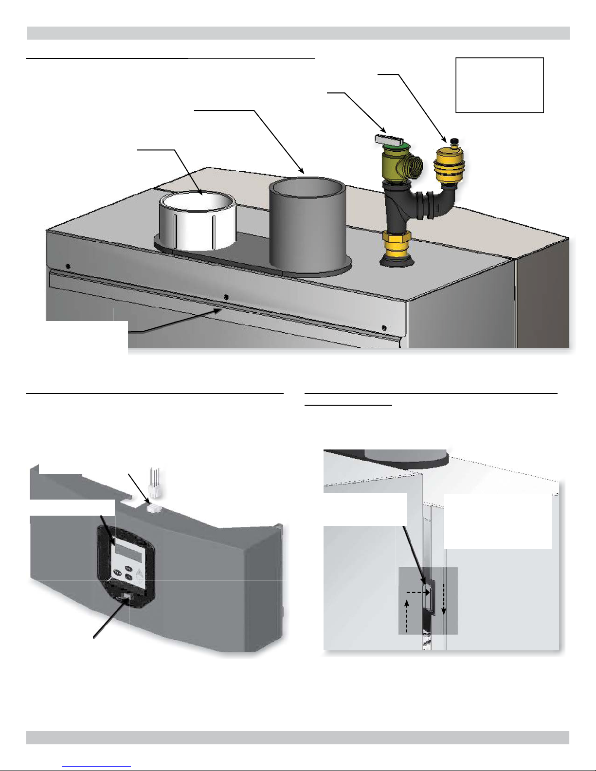
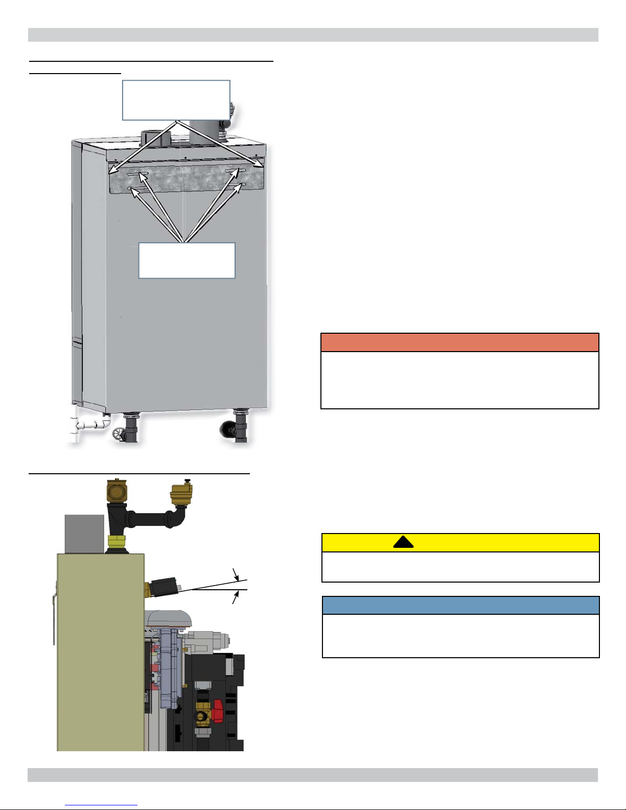
SAFETY RELIEF VALVE
AIR VENT
WALL MOUNT
SUPPORT
BRACKET
3 - COMPONENT LISTING
FIGURE 3-1 Boiler Components (Viewed from Back of Boiler)
SAFETY RELIEF VALVE
VENT CONNECTOR
COMBUSTION
AIR INLET
AIR VENT
NOTE:
See Section 5-3 For
Safety Relief Valve
Piping Instructions
WALL MOUNT
SUPPORT
BRACKET
FIGURE 3-2 Lower Jacket (Viewed from front of boiler)
Disconnect connector
Lower Jacket
Connector to User
Interface
(1) User Interface
before removing lower
jacket
FIGURE 3-3 Upper and Lower Jacket Latch (Viewed
from front of boiler)
Upper and Lower
Jacket Latch
Lift Jacket up,
engage jacket with
chassis,
push down.
Service Switch
8
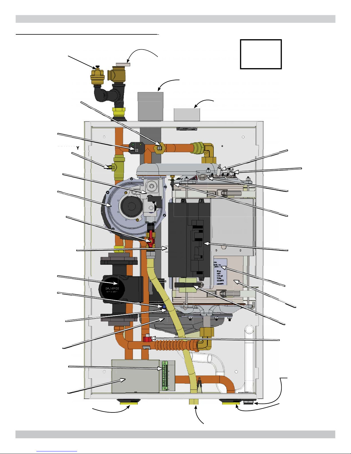
VALVE
AIR
BLOWER
(20) GAS (CONTROL)
VALVE
(22) LOW
WATER CUTOF
(23) SAFETY RELIEF VALVE
(28) AIR VENT
PUMP
(3) RETURN WATER
FROM HEATING
SYSTEM (IN)
(14) SUPPLY WATER TO
HEATING SYSTEM (OUT)
(26) GAS CONNECTION
PORT
JUNCTION BOX
(16) CONDENSATE
DRAIN
(
(13)
SURFACE TEMPERATURE
SWITCH
3 - COMPONENT LISTING
(36) ASME
PLATE
FIGURE 3-4 Boiler Components 50/75/100 MBH (View from Front of Boiler) As seen on front cover
NOTE:
(28) AIR VENT
(23) SAFETY RELIEF VALVE
See Section 5
For Piping
Instructions
(21) SUPPLY WATER
TEMPERATURE SENSOR
& HIGH LIMIT SWITCH
(22) LOW
WATER CUTOFF
(13)
INTERNAL PRIMARY
LOOP BALL VALVE
(20) GAS (CONTROL)
(10) CONDENSATE
VALVE
(19) COMBUSTION
(18) GAS SHUTOFF
(35) HEAT EXCHANGER
SURFACE TEMPERATURE
(17) HEAT EXCHANGER
(33) COMBUSTION
AIR
BLOWER
VALVE
(SHOWN IN OPEN
POSITION)
SWITCH
PUMP
(15) VENT
TEMPERATURE
SENSOR
ANALYSIS TEST
PORT
COLLECTOR
(25) VENT CONNECTOR
(2) COMBUSTION
AIR INLET
(5) IGNITER
(6) FLAME
SENSOR
(7) SIGHT GLASS
(32) FLUE
AIR MIXTURE
PRESSURE
TEST PORT
(29) BOILER
CONTROL
MODULE
Fuse and
Holder
(36) ASME
PLATE
(9) HEAT
EXCHANGER
(31) TRANSFORMER
(11) RETURN WATER
TEMPERATURE SENSOR
(4) LOW VOLTAGE
TERMINAL STRIP
(24) HIGH VOLTAGE
JUNCTION BOX
(14) SUPPLY WATER TO
HEATING SYSTEM (OUT)
(16) CONDENSATE
DRAIN
(3) RETURN WATER
FROM HEATING
(26) GAS CONNECTION
SYSTEM (IN)
9
VALVE
VALVE
CUTOFF
(23) SAFETY RELIEF VALVE
(28) AIR VENT
PUMP
(3) RETURN WATER
FROM HEATING
SYSTEM (IN)
(14) SUPPLY WATER TO
HEATING SYSTEM (OUT)
(4) LOW VOLTAGE
TERMINAL STRIP
(26) GAS CONNECTION
(24) HIGH VOLTAGE
JUNCTION BOX
(9) HEAT
(16) CONDENSATE
DRAIN
E
(13) INTERNAL PRIMARY
LOOP BALL VALVE
(35) HEAT
SENSOR
3 - COMPONENT LISTING
PLATE
E
FIGURE 3-5 Boiler Components 299 MBH (View from Front of Boiler)
(28) AIR VENT
(23) SAFETY RELIEF VALVE
(25) VENT CONNECTOR
NOTE:
See Section 5
For Piping
Instructions
(21) SUPPLY WATER
TEMPERATURE SENSOR &
HIGH LIMIT SWITCH
(22) LOW WATER
CUTOFF
(33) COMBUSTION
ANALYSIS TEST
PORT
(34) INTERNAL
PUMP RELAY
(29) BOILER CONTROL
(13) INTERNAL PRIMARY
MODULE
Fuse and Holder
LOOP BALL VALVE
(35) HEAT
EXCHANGER SURFACE
TEMPERATURE SWITCH
(17) HEAT EXCHANGER
PUMP
N
T
OL
(2) COMBUSTION
AIR INLET
(7) SIGHT GLASS &
(31) TRANSFORMER
(15) VENT TEMPERATURE
(15) V
(19) BLOWER
VENTURI
(6) FLAME SENSOR
(5) IGNITER
(9) HEAT
EXCHANGER
(20) GAS (CONTROL)
VALVE
(36) ASME
PLATE
SENSOR
(10) CONDENSATE
COLLECTOR
(4) LOW VOLTAGE
TERMINAL STRIP
(24) HIGH VOLTAGE
JUNCTION BOX
(14) SUPPLY WATER TO
HEATING SYSTEM (OUT)
10
(26) GAS CONNECTION
(18) GAS SHUTOFF
VALVE
(SHOWN IN OPEN
POSITION)
(11) RETURN
TEMPERATURE
SENSOR
(16) CONDENSATE
DRAIN
(3) RETURN WATER
FROM HEATING
SYSTEM (IN)
Model
Top (A)
Left Side (B)
Right Side (C)
Front (D)
Back (E)
Bottom (F)
Combustion Air/Vent
piping
Hot Water Piping
4 - LOCATING BOILER
4.1 Boiler Location Considerations
• Ambient room temperature always above 32°F (0°C) to
prevent freezing of liquid condensate.
FIGURE 4-1 Clearance to Combustible Materials
A
A
• Approved for installation in closets.
• Protect gas ignition system components from water
(dripping, spraying, rain, etc.) during operation and
service (circulator replacement, condensate trap, control
replacement, etc.).
• Wall mount only.
• Access to outdoors to meet minimum and maximum
pipe lengths for combustion air and vent piping. See
section 6.
• Disposal of condensate. See section 6.
• Drainage of water (or water - antifreeze solution) during
boiler service or from safety relief valve discharge. See
section 5.
• Access to system water piping, gas supply, and electrical
service. See sections 5, 7 and 8.
• Clearances to combustible materials and service
clearances. See Table 2 and fi gure 4-1.
• Multiple Boilers can be wall mounted, placed side by
side,
or back to back.
B
F
FLOOR
E
C
F
A
TABLE 2: BOILER CLEARANCES
Dimension
Model
Top (A)
Left Side (B)
Right Side (C)
Front (D)
Back (E)
Bottom (F)
Combustion Air/Vent
Hot Water Piping
(1)
Required distances measured from boiler jacket.
(2)
Service, proper operation clearance recommendation.
piping
Combustible
Materials
050/075/100/
150/200/299
0" (0 cm) 14" (36 cm)
0" (0 cm) 0" (0 cm)
0" (0 cm) 0" (0 cm)
0" (0 cm) 6" (16 cm)
0" (0 cm) 0" (0 cm)
0" (0 cm) 12" (32 cm)
0" (0 cm)
See local code 6" (16 cm)
(1)
E
F
FLOOR
Service
050/075/100/
150/200/299
6" (16 cm)
(1)(2)
D
F
11
!
4 - LOCATING BOILER
FIGURE 4-2 Wall Mount Bracket Engaged with
Bracket on Boiler
Center brackets. Avoid
overhang on sides of
wall mount bracket.
4 Slots for attaching
Wall Mount Bracket
to Studs
4.2 Pre-pipe supply and return water connections
with factory fi ttings before wall mounting.
4.3 Wall Mounting
Mount boiler on wall using wall mounting bracket included
with unit.
• Structure must be capable of supporting boiler weight
plus 60 lbs (28 kg). See Table 1, page 2.
• Wall mount bracket has 4 slots allowing mounting on
two (2) wall studs spaced at 11½" to 16½" on center.
See fi gure 4-2.
• Boiler includes (4) 3/8" x 3" lag screws and (4) washers
for attaching wall mount bracket to wood studs. Field
source appropriate fasteners for other wall constructions
(masonry, concrete).
• Attach wall mount bracket level on wall.
• Boiler must engage with wall mount bracket.
• Avoid overhang on sides of wall mount bracket. Verify
boiler bracket is centered on wall bracket. See fi gure
4-2.
WARNING
Fire, explosion hazard. Mount boiler vertically or
slightly tilted backward to insure proper function of
low water cutoff. Failure to follow these instructions
could result in death or serious injury.
FIGURE 4-3 Low Water Cutoff Orientation
5° ~ 15°
Factory Default
10°
• When mounting boiler onto wall insert two plastic
stoppers and two plastic plugs to packaging holes on
back of boiler. See parts listed on page 2, number 17
and 18.
• Mount boiler vertically or slightly tilted backward to
insure the low water cutoff functions properly. See
fi gure 4-3 for low water cutoff orientation.
!
CAUTION
Boiler weight exceeds 75 pounds (34 kg). Do not
lift boiler onto wall without assistance.
NOTICE
Lift boiler using chassis. Using front jacket, vent
piping, water or gas fi ttings to lift boiler may cause
damage to the boiler.
12
5 - HYDRONIC PIPING
5.1 General
• Install piping in accordance with authority having jurisdiction.
NOTICE
Use two (2) wrenches when tightening and fi tting
to pipe boiler's threaded fi ttings. Boiler's internal
piping can be damaged if subjected to excessive
torque.
• Support system piping and safety relief valve discharge
piping. Boiler's internal piping and wall mount bracket can
be damaged if subjected to excessive weight.
• Size central heating pump (and domestic hot water
pump, if used) for system requirements only. Internal
heat exchanger pump compensates for pressure drop
through boiler internal piping and heat exchanger.
• Thoroughly clean and fl ush system before connecting to
boiler.
• If oil is present in system water, use approved detergent to
wash system.
• Flush system to remove any solid objects such as metal
chips, fi bers, or Tefl on tape, etc.
5.2 Special Conditions
• System piping exposed to freezing conditions: Use
inhibited proplyene glycol solutions certifi ed by fl uid
manufacturer for use with closed water heating system.
Do not use automotive or ethylene glycol.
• Boiler installed above radiation level (or as required by
authority having jurisdiction). Integral low water cutoff
provided in boiler. See pages 9 & 10.
• Boiler used in connection with refrigeration system.
Install piping in parallel with boiler, with appropriate
valves to prevent chilled medium from entering boiler.
• System piping connected to heating coils located in air
handling unit exposed to refrigerated air circulation. Install
fl ow control valves or other automatic means to prevent
gravity circulation of boiler water during cooling cycle.
5.3 Safety Relief Valve and Air Vent
!
WARNING
• Poison hazard. Ethylene glycol is toxic. Do not
use ethylene glycol.
• Never use automotive or standard glycol antifreeze,
even ethylene glycol made for hydronic systems.
• Ethylene glycol can attack gaskets and seals used
in hydronic systems.
• Use only inhibited proplyene glycol solutions
certifi ed by fl uid manufacturer as acceptable for
use with closed water heating system.
• Thoroughly clean and fl ush any system that used
glycol before installing new Boiler.
• Provide user with Material Safety Data Sheet
(MSDS) on fl uid used.
NOTICE
Do not expose boiler and condensate piping to
freezing temperatures.
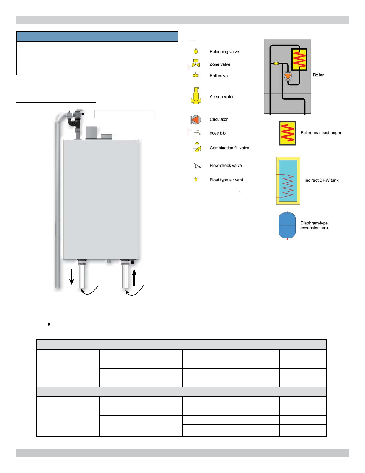
FIGURE 5-1 Safety Relief Valve & Air Vent (Viewed
from front of boiler)
Safety Relief
Valve
Air Vent
3/4"F x 3/4"M
NPT Tee
3/4 NPT
NOTICE
Boiler rated at 150 psig (1.03 MPa) maximum
allowable working pressure. Boiler provided with
30 psig (206 kPa) safety relief valve. Field source
safety relief valve for system pressures greater
than 25 psig. Temperature Pressure Gauge and Air
Vent satisfactory for 75 psig operation. Field source
temperature pressure gauge for system pressures
greater than 60 psig.
• Install safety relief valve and air vent using pipe fi ttings
provided with boiler. See fi gure 5-1
• Install safety relief valve with spindle in vertical position.
• Do not install shutoff valve between boiler and safety
relief valve.
3/4" x 1/4" NPT
90° Elbow
3/4" NPT
Nipple
Position Air Vent and Safety Relief Valve
to provide space for discharge piping.
13
5 - HYDRONIC PIPING
!
WARNING
Burn and scald hazard. Safety relief valve could
discharge steam or hot water during operation.
Install discharge piping per these instructions.
FIGURE 5-2 Safety Relief Valve Discharge Piping
Safety Relief Valve
• Install discharge piping from safety relief valve. See
fi gure 5-2.
• Use ¾" or larger pipe.
• Use pipe suitable for temperatures of 375°F (191°C)
or greater.
• Individual boiler discharge piping shall be independent
of other discharge piping.
• Size and arrange discharge piping to avoid reducing
safety relief valve relieving capacity below minimum
relief valve capacity stated on rating plate.
• Run pipe as short and straight as possible to location
protecting user from scalding and properly drain
piping.
• Install union, if used, close to safety relief valve outlet.
• Install elbow(s), if used, close to safety relief valve
outlet and downstream of union (if used).
• Terminate pipe with plain end (not threaded).
5.4 Trim Piping
• Temperature - Pressure Gauge. Install temperature
pressure gauge using nipple, tee and bushing provided
with boiler. See fi gure 5-3.
Check Local Codes
For Maximum
Distance To Floor
FIGURE 5-3 Temperature Pressure Gauge and Drain
Valve Installations
Gas Supply
Temperature Pressure
Gauge shown at
System Supply
Connection
Drain Valve shown
at System Return
Connection to Boiler
5.5 System Piping
• Drain Valve. Install drain valve using nipple, tee and
bushing provided with boiler. See fi gure 5-3.
• See Table 3 for basic system piping confi gurations.
• Systems with automatic fi ll valves require back fl ow
prevention device.
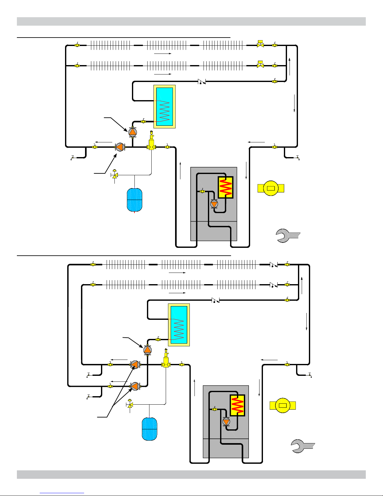
• Single boiler system. See fi gures 5-4, 5-5, 5-6, 5-7A, & B
for general guidance. Additional considerations:
• Boiler control is designed for single central heating
pump. Installer responsible for integration of
multiple central heating pumps.
• Boiler control allows domestic hot water
prioritization. Function could be lost if central
heating pump not directly connected to control
system.
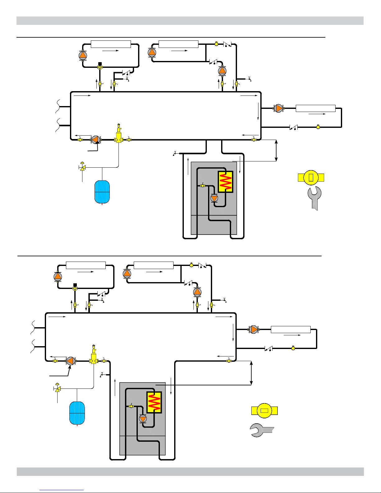
• Multiple boiler system.
guidance. Additional considerations:
• Control system requires equivalent water
temperatures entering each boiler to properly
sequence and adjust system supply temperature.
• Install multi boiler sensor kit. See "Parts, Kits &
Optional Accessories" manual for part number.
• Heating system with existing primary loop, close internal
primary loop ball valve.
• Heating system without existing primary loop, leave internal
primary loop ball valve open to use internal primary loop.
See fi gure 5-8A, B & C
for general
14
5 - HYDRONIC PIPING
NOTICE
Illustrations are meant to show system piping
concept only. Installer responsible for all
equipment and detailing required by authority
having jurisdiction.
FIGURE 5-4 System Piping
Safety Relief Valve
MOUNTED
Piping Legend
WALL
ONLY
Pipe to
condensate
drain
Multiple Boilers
Single Boiler
System
Supply
System
Return
Table 3 - System Piping Confi gurations
Two Pipe Zoned System
Primary/Secondary Pumping
Two Pipe Zoned System
Primary/Secondary Pumping
With Zone Valves fi gure 5-5
With Zone Pumps fi gure 5-6
Closed External Primary Loop
Open External Primary Loop fi gure 5-7B
With Zone Valves fi gure 5-8A
With Zone Pumps Not Shown
Closed External Primary Loop fi gure 5-8B
Open External Primary Loop
fi gure 5-7A
fi gure 5-8C
15
5 - HYDRONIC PIPING
FIGURE 5-5 Single Boiler Two-Pipe Zoned System With Zone Valves
DHW
Pump
CH/System
Pump
Heat exchanger
ball valve open
(as shipped)
FIGURE 5-6 Single Boiler Two-Pipe Zoned System With Zone Pumps
DHW
Pump
Zone
Pump
3/8"/10mm Open
End
Wrench
Heat exchanger
ball valve open
(as shipped)
3/8"/10mm Open
End Wrench
16
5 - HYDRONIC PIPING
FIGURE 5-7A Single Boiler Using Primary/Secondary Pumping With Closed External Primary Loop
HeatingLoad HeatingLoad
12"(305mm) Maximum
separation
12"(305mm)
CH/System
Pump
Maximum
separation
Existing closely spaced tees
in primary system loop
Limit length
HeatingLoad
to
5' (1.6m)
Heating system
with existing
primary loop.
Internal primary
3/8"/10mm
Open End Wrench
loop ball valves
closed
FIGURE 5-7B Single Boiler Using Primary/Secondary Pumping With Open External Primary Loop
HeatingLoad HeatingLoad
12"(305mm) Maximum
12"(305mm)
CH/System
Pump
Maximum
separation
separation
Existing closely spaced tees
in primary system loop
Limit length
HeatingLoad
to
5' (1.6m)
Internal primary loop
ball valves open.
Heating system
without existing
3/8"/10mm
Open End Wrench
primary loop.
17
5 - HYDRONIC PIPING
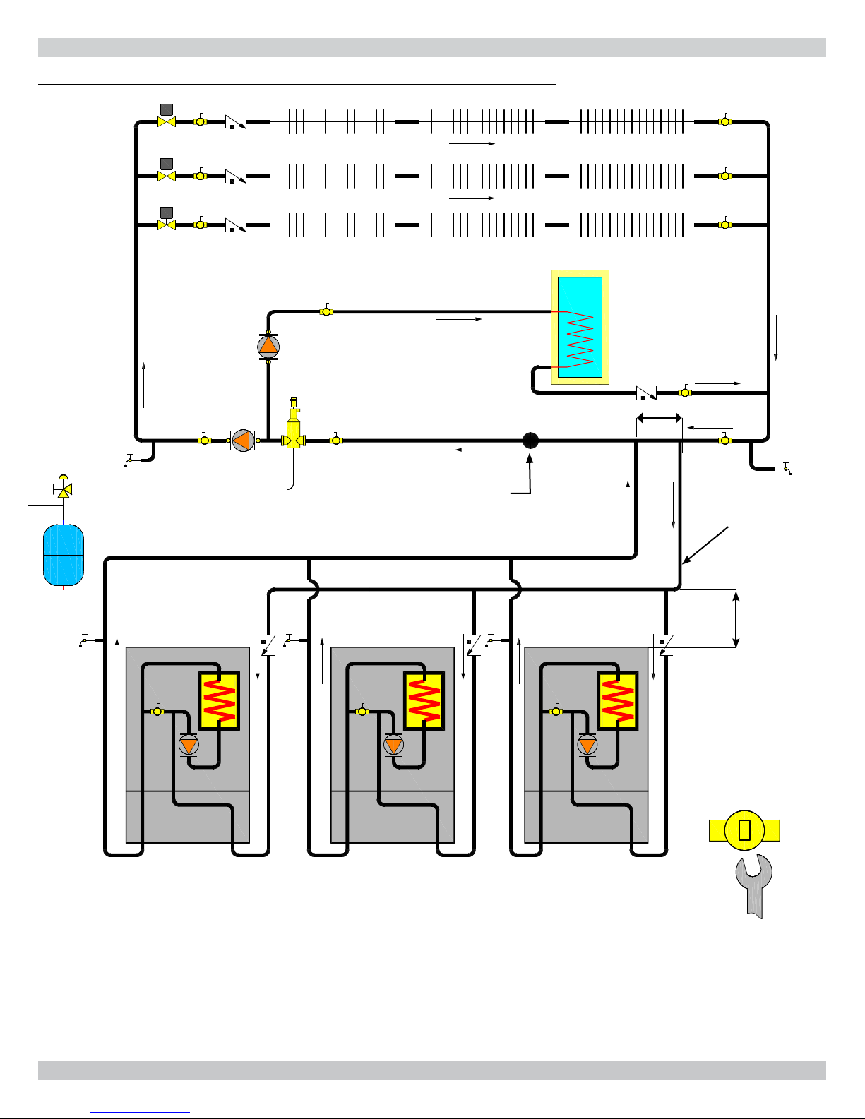
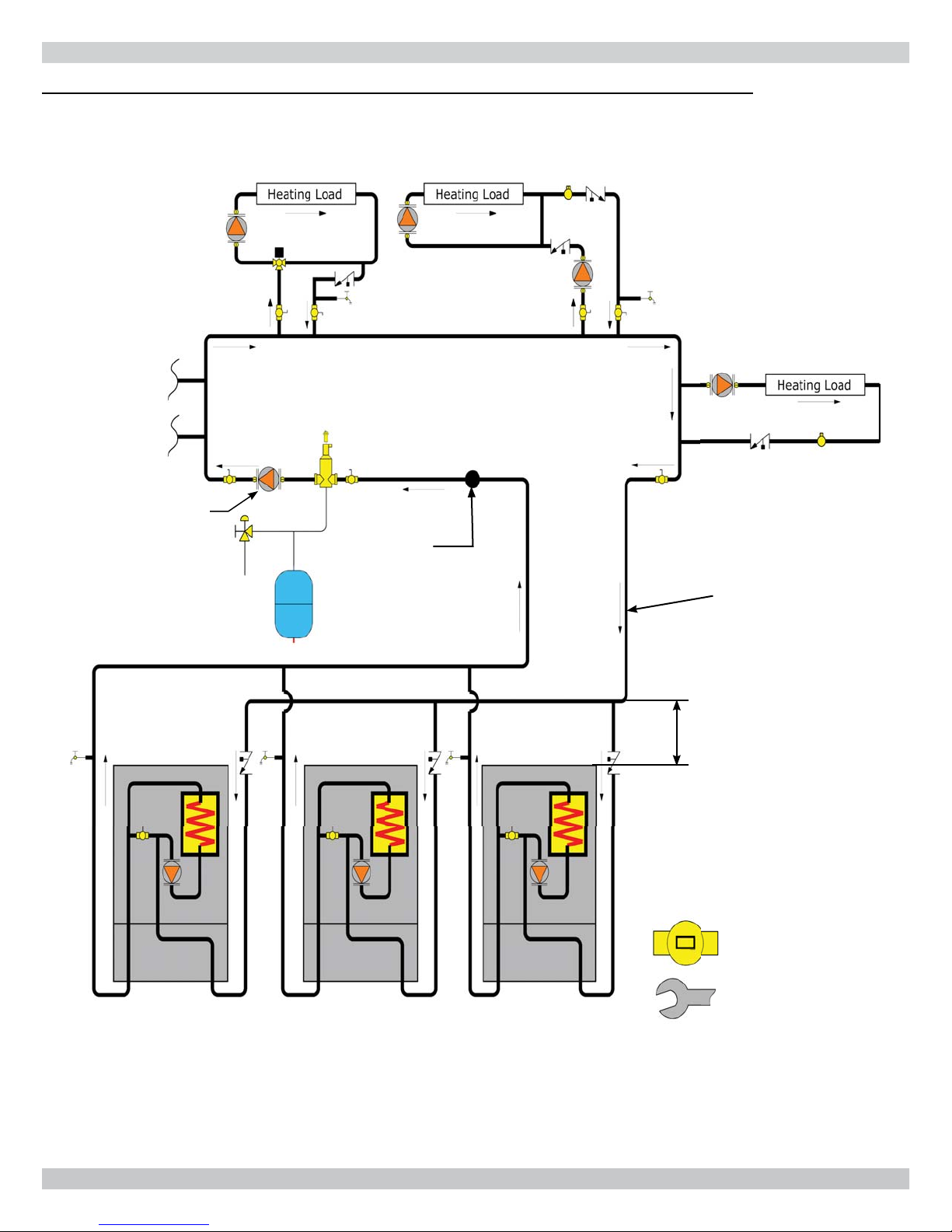
FIGURE 5-8A Multiple Boiler Two Pipe Zoned System With Zone Valves - (See Multiple Boiler Guide)
DHW
Pump
CH/System
Pump
12"/305mm Maximum Separation
System
Temperature
Sensor
Size common piping
per maximum heat
capacity of entire
system
Limit
length to
5' (1.6m)
All internal
primary loop
ball valves
closed
Up to 16
boilers
(See Multiple Boiler Guide)
18
3/8"/10mm Open End
Wrench
5 - HYDRONIC PIPING
FIGURE 5-8B Multiple Boilers Using Primary/Secondary Pumping with Closed External Primary Loop
HeatingLoad HeatingLoad
12"/305mm Maximum Separation
12"/305mm
Maximum
Separation
CH/System
Pump
System
Temperature
Sensor
Existing closely spaced tees
in primary system loop
HeatingLoad
Size common piping
per maximum heat
capacity of entire
system
Limit
length to
5' (1.6m)
Up to 16
boilers
All internal
primary loop
ball valves
closed
3/8"/10mm Open End
Wrench
19
5 - HYDRONIC PIPING
5-8C Multiple Boilers Using Primary/Secondary Pumping with Open External Primary Loop
12"/305mm Maximum Separation
12"/305mm
Maximum
Separation
CH/System
Pump
System
Temperature
Sensor
Existing closely spaced tees
in primary system loop
Size common piping
per maximum heat
capacity of entire
system
Up to 16
boilers
Limit
length to
5' (1.6m)
Heat exchanger
ball valve open
(as shipped)
3/8"/10mm Open End
Wrench
20
6 - COMBUSTION AIR AND VENT PIPING
6.1 General
This boiler requires a dedicated direct vent system.
Install combustion air and vent piping in accordance
with these instructions, authority having jurisdiction,
and:
• USA - National Fuel Gas Code, ANSI 223.1/NFPA 54.
• Canada - Natural Gas and Propane Installation Code,
CAN/CSA B149.1
Vent connections serving appliances vented by natural draft
shall not be connected into any portion of mechanical draft
systems operating under positive pressure.
Install vent system in accordance with these instructions.
6.2 Removal of Existing Boiler From Common
Vent System
When existing boiler is removed from common venting
system, common venting system is likely to be too large for
proper venting of appliances remaining connected to it.
After removal of existing boiler, following steps shall
be followed with each appliance remaining connected to
common venting system placed in operation, while other
appliances remaining connected to common venting system
are not in operation:
• Seal any unused openings in common venting system.
• Visually inspect venting system for proper size and
horizontal pitch. Determine there is no blockage or
restrictions, leakage, corrosion and other defi ciencies
which could cause an unsafe condition.
• When practical, close all building doors, windows, and
all doors between space in which appliances remaining
connected to common venting system are located
and other spaces of building. Turn on clothes dryer
and any appliance not connected to common venting
system. Turn on exhaust fans, such as range hoods and
bathroom exhaust so they will operate at maximum
speed. Do not operate summer exhaust fan. Close
fi replace dampers.
• Any improper operation of common venting system
should be corrected so installation conforms with National
Fuel Code, ANSI Z223.1/NFPA 54 and/or Natural Gas
and Propane Installation Code, CAN/CSA B149.1.
When re-sizing any portion of common venting system,
common venting system should be re-sized to approach
minimum size as determined using appropriate tables in
Chapter 13 of the National Fuel Gas Code, ANSI Z223.1/
NFPA 54 and/or Natural Gas and Propane Installation
Code, CAN/CSA B149.1.
6.3 Venting Materials
• See Table 4
Table 4 - Combustion air and vent pipe fi ttings
must conform with the following:
Item Material Standards
PVC schedule 40 ANSI/ASTM D1785
PVC - DWV ANSI/ASTM D2665
CPVC schedule 40
Vent Pipe
and Fittings
Pipe
Cement/
Primer
• IPEX is approved vent manufacturer in Canada listed
to ULC-S636.
• IPEX System 636 Cements and Primers are approved
in Canada listed to ULC-S636.
SDR-21 & SDR-26 PVC ANSI/ASTM D2241
ABS-DWV ANSI/ASTM D2661
Schedule 40ABS ANSI/ASTM F628
PP (Polypropylene)
Pipe and Components
PVC ANSI/ASTM D2564
CPVC ANSI/ASTM F493
Schedule 40 ABS ANSI/ASTM D2235
ANSI/ASTM D1784/
F441
UL 1738
ULC S636-08
• Turn on appliance being inspected. Follow lighting
instructions. Adjust thermostat so appliances will operate
continuously.
• Test for spillage at draft hood relief opening after 5
minutes of main burner operation. Use fl ame of match or
candle, smoke from cigarette, cigar or pipe.
• Determine each appliance remaining connected to
common venting system properly vents when tested
as outlined above. Then return doors, windows,
exhaust fans and any other gas-burning appliance to
their previous condition of use.
Use of cellular core PVC (ASTM F891), cellular core CPVC, or Radel® ,
(Polyphenolsulfone) in venting systems shall be prohibited.
!
WARNING
Use of cellular core PVC for venting fl ue gas could
result in death, or serious injury.
21
6 - COMBUSTION AIR AND VENT PIPING
6.4 Vent Pipe Installation
• Minimum and maximum combustion air and vent pipe
lengths listed in Table 5. Pipe length counted from
combustion air connector to termination.
• Install fi eld-sourced 2" to 3" transition, if used, in vertical
section at combustion air inlet and vent connector.
• 90° elbows equivalent to 5.0 ft (1.6 m). 45° elbows
equivalent to 3.5 ft (1.1 m). 2" to 3" transition has no
equivalent length. See Table 6.
• Use fl exible Polyproplyene piping (PP) in a vertical
position only. Check PP pipe manufacturer for details.
Each foot of PP fl exible pipe is equivalent to 2⅝ feet of
smooth pipe of same diameter.
• Slope vent pipes minimum 1/4" per foot (21 mm/m)
back toward boiler. Support horizontal sections to
prevent sags capable of accumulating condensate.
• Support piping in accordance with pipe manufacturer's
instruction and authority having jurisdiction. In absence
of manufacturer's instruction use pipe hooks, pipe
straps, brackets, or hangers of adequate and strength
located at intervals of 4 ft (1.2m) or less. Allow for
expansion/contraction of pipe.
• Canadian installations only. All venting material, primer
and glue must be listed to ULC S636.
• Canadian installations only. First 3 ft (0.9 m) of
plastic vent pipe from vent connector must be readily
accessible for visual inspection.
6.5 Vent Termination
• Terminate combustion air and vent pipes with fi ttings or
concentric vent kit.
A. See "Parts, Kits and Optional Accessories" manual
for concentric vent kit part numbers.
B. Use horizontal pipe for vent and 90° elbow for
combustion air termination when using fi ttings.
• Terminate combustion air and vent pipes in same
atmospheric pressure zone through exterior sidewall or
roof.
• Locate combustion air termination as far as possible
from swimming pool, swimming pool pump house, and
other sources of airborne chlorine.
• Locate combustion air and vent terminals as required by
authority having jurisdiction.
• Combustion air and vent piping must be air tight and
water tight.
• Certifi ed vent system components must NOT be
interchanged with other vent systems or unlisted pipe/
fi ttings.
Vent extending through exterior wall shall not
terminate adjacent to wall or below building
extensions such as eaves, balconies, parapets or
decks. Failure to comply could result in death or
serious injury.
Table 5 - Combustion Air and Vent Piping Length
Minimum/Maximum Vent Lengths
2” Pipe 3” Pipe 4” Pipe
Model 050 075/100 075/100 150/200 299 299
Min.
Max.
For Example: Boiler can be installed on outside wall and vented with one 90° elbow and 1 ft (0.30 m) of vent pipe.
6 ft.
(1.8 m)
100 ft.
(30.5 m)
6 ft.
(1.8 m)
50ft.
(15.2 m)
6 ft.
(1.8 m)
100 ft.
(30.5 m)
Table 6 -Equivalent Length of Venting Components
Equivalent Length of Venting Components
Component Feet Meters
90° Elbow 5 1.6
45° Elbow 3 1/2 1.1
2" x 4" Adapter 0 0
3" x 4" Adapter 0 0
Concentric Vent Kit 5 1.6
Polypropylene Flexible Pipe per Foot 2 5/8 0.8
6 ft.
(1.8 m)
100 ft.
(30.5 m)
!
WARNING
6 ft.
(1.8 m)
25 ft.
(7.7 m)
6 ft.
(1.8 m)
100 ft.
(30.5 m)
22
6 - COMBUSTION AIR AND VENT PIPING
6.6 Venting Confi gurations
Various venting confi gurations can be applied to this boiler.
For guidance see Venting Confi guration Table 7 and
corresponding fi gures.
Table 7 - Venting Confi gurations
Flue Gas Location
Roof
Combustion Air
Location
Roof
Side Wall Single Pipe fi gure 6-8
Inside Air Single Pipe fi gure 6-9
Roof Single Pipe fi gure 6-10
NOTICE
Use of vent covers may cause freezing. If using
vent covers overall vent length must be considered.
Failure to heed this information may compromise
operation of this boiler.
Flue Gas
Terminals
Two Pipe fi gure 6-1
Concentric fi gure 6-7
Corresponding Figures
Side Wall
Two Pipe fi gures 6-2, 6-3
Side Wall
Concentric fi gures 6-4, 6-5, 6-6
Inside Air Single Pipe fi gure 6-11
23
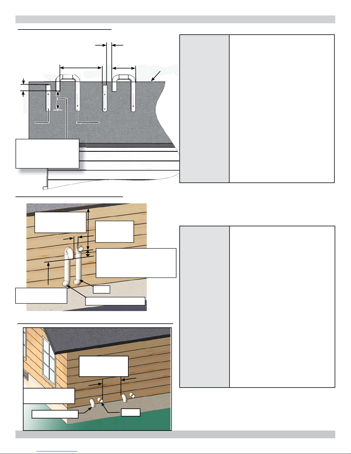
FIGURE 6-1 Two Pipe Roof Vent
3" (80mm)
Minimum
12" (305mm)
Minimum
8" (203mm)
Minimum
Vent Combustion
Air
12" (305mm) US,
18" (458mm) Canada
Minimum Above
Anticipated Snow Line
6 - COMBUSTION AIR AND VENT PIPING
3" (80mm) Minimum horizontal
separation between combustion air
15" (381mm)
Maximum
Roof Line
Roof
Terminations
intake and vent of same appliance.
8" (203mm) Minimum vertical
separation between combustion
air intake and vent of different
appliances.
15" (381mm) Maximum horizontal
length of vent.
Minimum vent/intake between
different appliances 12" (305mm).
Maximum allowable total vertical
vent length with outside exposure is
10 ft.(3.05m).
Abandoned unused masonry
chimney may be used as chaseway
for combustion air and vent. Both
combustion air and vent pipe must
exit above top of chimney with
clearances as shown in fi gure 6-1.
FIGURE 6-2 Two Pipe Side Wall Vent
12" (305mm)
Minimum From
Overhang
See Snow & Ice
Page 22
FIGURE 6-3 Two Pipe Side Wall Vent (Multiple Appliances.
See snow & ice
page 23
3" (80mm)
Minimum
Separation
12" (305mm) Separation
Between Bottom Of
Combustion Air Intake And
Bottom Of Vent
Vent
Combustion Air
12" (305mm)
Minimum
Separation
Side Wall
Terminations
3" (80mm) Minimum horizontal
separation between combustion air
intake and vent terminations.
8" (203mm) Minimum vertical
separation between combustion air
intake and vent terminations.
12" (305mm) Separation between
bottom of combustion air intake and
bottom of vent.
Multiple terminations as shown
in 6-1, 6-2, and 6-3 must be
a minimum of 12” (305mm)
horizontally between vent of one
termination and air intake of next
appliance.
Maximum allowable total outside
exposure vent length equals 10 ft.
(3.05m).
Maintain a pitch of 1/2" per ft.
(42mm/m) outside exposure back to
boiler to ensure proper condensate
drainage for horizontal runs.
Combustion Air
Vent
24

6 - COMBUSTION AIR AND VENT PIPING
FIGURE 6-4 Side Wall Concentric Terminal FIGURE 6-5 Side Wall Concentric Terminal Multiple
Appliances
1"(2.54cm)
1" (25.4mm)
Maximum
Maximum
Vent
Combustion
Air
FIGURE 6-6 Concentric Terminal Connection
*2 or 3" (51 or 77 mm) Diameter
PVC intake/combustion air
Roof
1" (25mm)
Maximum
* See Note
Below
Combustion
Air
Overhang
12" (305mm) Minimum
36"(0.9m) Minimum
Vent
Maintain 12"(30cm) US
(18"(46cm) Canada)
highest anticipated
Clearance Above
snow level or grade
Highest Anticipated
Snow Level Or Grade
Maintain 12"
clearance above
*Must be less than 4" (102mm) or greater than 24"
(610mm) Horizontal distance between end bells of each air
intake to prevent fl ue gas recirculation.
Note: Securing strap must
be fi eld installed to prevent
movement of termination
kit in side wall
Combustion Air
OD 3½" (
89mm)
- *2" (
51mm)
kit
OD 4½" (114mm) - 3" (77mm) kit
** Note Overall length may be modifi ed by cutting or extending
both combustion air and vent pipes. 12" (305mm) is minimum
allowable length and 60" (1.2m) is maximum allowable length for
this dimension.
SDR-26 PVC (D2241) only may be used for extending pipes.
Do not use Schedule 40 PVC or use couplings to extend pipes.
Dimension will change if intake/vent pipes are lengthened or
shortened.
**See
Note
*2" (
51mm)
Diameter = 41" Length (1.1m)
3" (77mm) Diameter = 47" Length (1.2m)
1"(25.4mm)
Maximum
Vent
Combustion Air
* Note: 2" (51mm) For use with models 050/075/100.
3" (77mm) For use with models 075/100/150/200/299
4" (101mm) For use with model 299
25
6 - COMBUSTION AIR AND VENT PIPING
FIGURE 6-7 Concentric Roof Terminal
Vent
Maintain 12"(305mm) US
(18"(457mm) Canada)
clearance above highest
Combustion Air
Roof boot/fl ashing
(fi eld supplied)
Note: Support must
be fi eld installed to
secure termination
kit to structure
Vent
FIGURE 6-8 Flue on Roof, Air Intake on Side Wall
Vent
anticipated snow level 24"
(610mm) above roof
Support
(fi eld supplied)
Combustion Air
Maintain 12"(305mm) US
(18"(457mm) Canada)
clearance above highest
anticipated snow level 24"
(610mm) above roof
Concentric
Vent Roof
Terminations
Glue inner vent pipe to prevent
recirculation.
Maintain 12" (305mm) US
(18"(457mm) Canada) minimum
clearance above highest
anticipated snow level. Maximum of
24"(610mm) above roof.
Support must be fi eld installed to
secure termination kit to structure.
Elbow, roof boot/fl ashing fi eld supplied.
Allowed Wall/Roof thickness 1/2"-30"
(12.7mm - 762mm).
Vertical concentric vent system can be
installed in unused masonry chimney.
Contact Technical Support 800-
325-5479 for questions regarding
installation or use.
Terminate vent system bottom, minimum
12" (300 mm) above highest anticipated
snow level.
Combustion Air
12" (305mm)
Anticipated
Snow Line
Ground Level
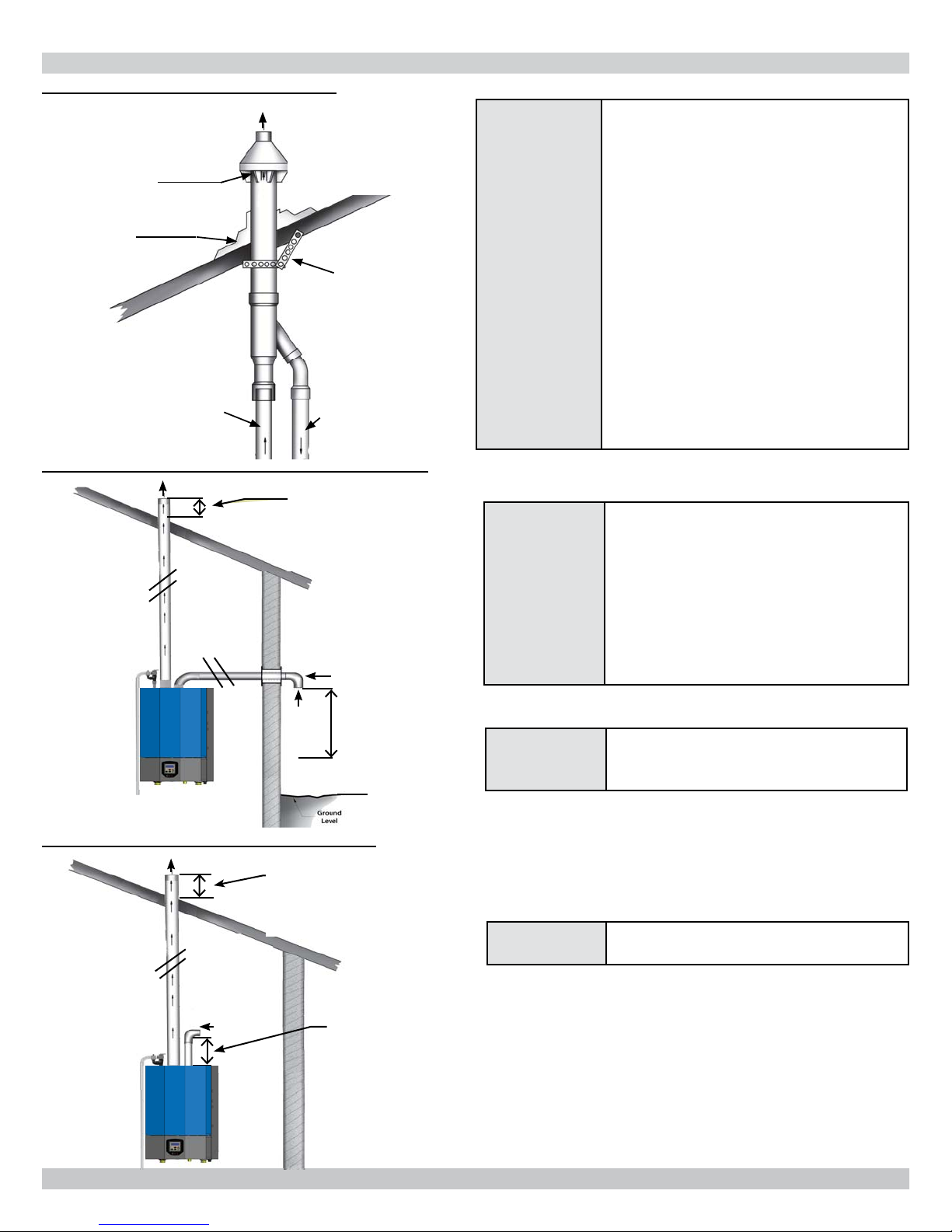
FIGURE 6-9 Flue on Roof, Combustion Air
Vent
Combustion
Air
Maintain 12"(305mm) US
(18"(457mm) Canada)
clearance above highest
anticipated snow level 24"
(610mm) above roof
24" (610mm)
* Minimum Length
Grade, Snow
& Ice
Doors &
Windows
* See Tables
4 & 5
Avoid locations where snow may drift
and block vent and combustion air.
Ice or snow may cause boiler to shut
down if vent or combustion air becomes
obstructed.
Combustion air and vent termination
must be 12" (305mm) from or below
doors, windows or gravity inlet.
Combustion air and Vent Piping Length
Page 22 .
26
 Loading...