

Page 1
USER'S
INFORMATION
MANUAL
DCC-150/205
DCB -125/165
WARNING: If the information in this manual
is not followed exactly, a re or explosion
may result causing property damage, personal
injury or loss of life.
- Do not store or use gasoline or other
ammable vapors and liquids in the vicinity
of this or any other appliance.
- WHAT TO DO IF YOU SMELL GAS
• Do not try to light any appliance.
• Do not touch any electrical switch;
do not use any phone in your building.
• Immediately call your gas supplier
from a neighbor's phone. Follow the
gas supplier's instructions.
• If you cannot reach your gas supplier,
call the re department.
- Installation and service must be performed
by a qualied installer, service agency or the
gas supplier.
Information and specications outlined in this manual in effect at the
time of printing of this manual. Manufacturer reserves the right to
discontinue, change specications or system design at any time without
notice and without incurring any obligation, whatsoever.
Manufactured by:
ECR International Inc.
2201 Dwyer Avenue, Utica, NY 13501
Tel. 800 253 7900
www.ecrinternational.com
PN 240011960 REV A, [01/01/2018]
Page 2
1 - GENERAL
1.1 GENERAL
This boiler has few USER serviceable parts. Maintenance
and Service shall be completed by qualied agency.
!
WARNING
Fire, explosion, asphyxiation and electrical shock
hazard. Improper maintenance and service could
result in death or serious injury. Read this manual
and understand all requirements, including use of
qualied service agent where directed.
1.2 BECOME FAMILIAR WITH SYMBOLS
IDENTIFYING POTENTIAL HAZARDS.
This is the safety alert symbol. Symbol alerts you to
potential personal injury hazards. Obey all safety messages
following this symbol to avoid possible injury or death.
!
DANGER
Indicates a hazardous situation which, if not avoided,
WILL result in death or serious injury
!
WARNING
Indicates a hazardous situation which, if not avoided,
could result in death or serious injury.
!
CAUTION
Indicates a hazardous situation which, if not avoided,
could result in minor or moderate injury.
!
WARNING
Following service procedures shall be performed
by qualied service agent. Boiler owner shall not
attempt these steps. Failure to do so could result in
death or serious injury.
!
WARNING
Combustion chamber insulation in this product
contains ceramic ber material. Ceramic bers
can be converted to cristobalite in very high
temperature applications. The International Agency
for Research on Cancer (IARC) has concluded,
Crystalline silica inhaled in the form of quartz
or cristobalite from occupational sources is
carcinogenic to humans (Group1). Avoid breathing
dust and contact with skin and eyes. Use NIOSH
certied dust respirator (N95). This type of
respirator is based on the OSHA requirements
for cristobalite at the time this document was
written. Other types of respirators may be needed
depending on the job site conditions. Current
NIOSH recommendations can be found on the
NIOSH website at http://www.cdc.gov/niosh/
homepage.html. NIOSH approved respirators,
manufacturers, and phone numbers are also listed
on this website. Wear long-sleeved, loose tting
clothing, gloves, and eye protection. Apply enough
water to the combustion chamber lining to prevent
dust. Wash potentially contaminated clothes
separately from other clothing. Rinse clothes
washer thoroughly.
NIOSH stated First Aid. Eye: Irrigate immediately.
Breathing: Fresh air.
NOTICE
Used to address practices not related to personal
injury.
Use of CO monitor is manufacturer recommended and may
be requirement of local jurisdiction.
1.3 WHAT TO DO SHOULD OVERHEATING OCCUR
Do not turn off or disconnect electrical supply to pumps.
Shut off gas supply at location external to appliance.
1.4 WHAT TO DO IF BOILER OR ANY PART HAS
BEEN UNDER WATER
Do not use boiler if any part has been under water.
Immediately call a qualied service technician to inspect
boiler and to replace any part of control system and any
gas control which has been under water.
2
PN 240011960 REV A, [01/01/2018]
Page 3
2 - OPERATING INSTRUCTIONS
FOR YOUR SAFETY READ BEFORE OPERATING
!
WARNING
If you do not follow these instructions
exactly, a re or explosion may result
causing property damage, personal injury
or loss of life.
• This appliance is equipped with an ignition device
which automatically lights burner. Do NOT try to
light this burner by hand.
• Before operating smell all around appliance area for
gas. Be sure to smell next to oor because some gas
is heavier than air and will settle to the oor.
• Use only your hand to turn the gas shutoff valve.
Never use tools. If valve will not turn by hand, do not
try to repair it, call a qualied service technician. Force
or attempted repair may result in re or explosion.
• Do not use this appliance if any part has been
under water. Immediately call a qualied service
technician to inspect appliance and to replace any part
of control system and any gas control which has been
under water.
• Do not block the ow of combustion or
ventilation air to boiler.
!
CAUTION
WHAT TO DO IF YOU SMELL GAS
• Do not try to light any appliance.
• Do not touch any electrical switch; do not
use any phone in your building.
• Immediately call your gas supplier from a
neighbor’s phone. Follow the gas supplier’s
instructions.
• If you cannot reach your gas supplier, call
the re department.
2.1 OPERATION
Boiler is wall mounted, fan assisted room-sealed
combination boiler, providing both central heating and
domestic hot water depending on model purchased.
• After initial lighting, boiler will provide central heating
(as required).
• Hot water is available whenever a hot tap is open
(Combi models only).
2.2 OPERATING INSTRUCTIONS
Stop! Read ALL Safety information above.
• Set thermostat to lowest setting.
• Turn “OFF” all electrical power to appliance.
• This appliance is equipped with an ignition device which
automatically lights the burner. Do not try to light
burner by hand!
• Turn gas shutoff valve clockwise to closed position.
Handle should be perpendicular to gas pipe.
• Wait 5 minutes for any gas to clear. Smell for gas,
including near oor. If you smell gas, STOP! Follow
instructions on this page: “What To Do If You Smell
Gas.” If you do not smell gas, go to next step.
• Turn gas shutoff valve counter clockwise to the open
position. Handle should be parallel to gas pipe.
• Replace front jacket panel.
• Turn “ON” electrical power to appliance.
• Set thermostat to desired setting.
• Set correct operating mode. See 2.4
• If the appliance will not operate, follow instructions TO
TURN OFF GAS TO APPLIANCE and call your service
technician or gas supplier.
2.3 TURN OFF GAS TO APPLIANCE
• Set thermostat to lowest setting.
• Turn “OFF” all electric power to appliance if service is
to be performed.
• Turn gas shutoff valve handle clockwise to closed
position. Handle should be perpendicular to gas pipe.
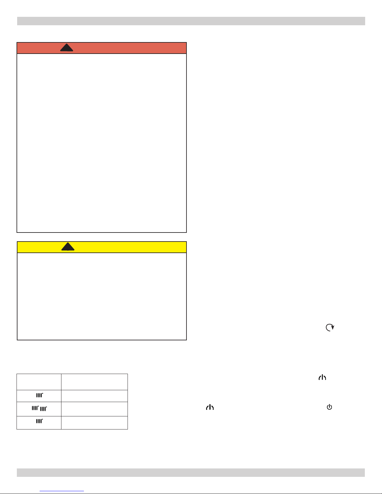
2.4 OPERATING MODES
SYMBOL
DISPLAYED
OPERATING MODE
DHW
DHW & HEATING
HEATING ONLY
To enable the appliance in DHW - Heating or Heating only press
repeatedly and choose one of three available modes.
To disable the boiler operating modes and keep the frost protection
function enabled, press for at least 3 seconds. Just the symbol
appears on the display (the display backlighting ashes if the boiler is
blocked).
3
PN 240011960 REV A, [01/01/2018]
Page 4

3.1 USER CONTROLS
BUTTON Explanation:
DHW temperature adjustment
(+ to increase the temperature and – to decrease it)
Heating water temperature adjustment
(+ to increase the temperature and – to decrease it)
Boiler operating information
Operating mode:
DHW – DHW & Heating – Heating Only
Off – Reset – Exit menu/functions
SYMBOL Explanation:
3 - CONTROL
O f f : H e a t i n g a n d D H W d i s a b l e d
(only boiler frost protection is active)
Ignition fault DHW operating mode enabled
Boiler/system water pressure low Heating mode enabled
Call a qualied service technician Programming menu
Manually resettable fault
Fault in progress Set unit of measurement
3.2 CENTRAL HEATING SYSTEM PRESSURE
Regularly check the pressure displayed on the pressure
gauge "B" is between 14.50 and 21.76 psi (1.0 - 1.5 bar),
with the boiler cold.
If the pressure is less than 14.50 psi, or higher than 21.76
psi call an authorized SERVICE technician.
Burner lit
Boiler information menu
4
PN 240011960 REV A, [01/01/2018]
Page 5

3 - CONTROL
3.3 TEMPERATURE CONTROL
Press and respectively to adjust the CH and
DHW ow temperature (if an indirect storage tank is tted).
When the burner is lit, display shows the symbol .
HEATING: while boiler is operating in heating mode, the
display shows the ashing symbol and the heating ow
temperature °F / °C.
When connected to an Outdoor Temperature Sensor,
indirectly adjusts room temperature (factory setting 68°F /
20°C).
DHW: While boiler is operating in DHW mode, display
shows the ashing symbol and heating ow temperature
°F / °C.
3.4 BOILER INFORMATION MENU (See Below)
Press and hold for at least 1 second, to display the
information indicated in the table. Press to exit.
DESCRIPTION DESCRIPTION
00
01
02
03
04
05
06
07
08
Secondary fault internal code 09
Heating ow temperature (°F/°C) 10/11
Outdoor temperature (°F/°C) 12
Indirect Tank DHW temperature (boiler CH only) 13
Domestic hot water temperature (boiler with plate
exchanger)
Water pressure in heating system (PSI/bar) 15
Heating return temperature (°F/°C) 16
Thermo fuse status (000/001) 17
Not used 18
14
3.5 SHUTTING OFF THE BOILER
To turn off the boiler, disconnect the electric power supply.
In the “Off” operating mode the boiler stays off but the
electrical circuits remain powered and the frost protection
function remains active.
3.6 FROST PROTECTION MODE
The electronic boiler management system includes a
“frost protection” function for the heating system which,
when delivery temperature falls below 41°F (5°C), lights
the burner until a delivery temperature of 86°F (30°C) is
reached.
Setpoint Central Heating (°F/°C)
Manufacturing information
Flue sensor temperature (°F/°C)
Manufacturing information
Identication Open Therm communication
Manufacturing information
Manufacturing information
Fan speed (“i17”x100)
Manufacturing information
This function is only operative if the boiler is electrically
powered and there is gas with normal system pressure and
the ue is not blocked.
5
PN 240011960 REV A, [01/01/2018]
Page 6

3 - CONTROL
3.6 ERROR MESSAGES AND RESETTING THE BOILER
ERROR DESCRIPTION OPERATION
09 Gas valve connection fault. Call an authorized SERVICE technician
10 Outdoor sensor fault . Call an authorized SERVICE technician
15 Gas valve error. Call authorized SERVICE technician
20 Central Heating NTC sensor fault. Call authorized SERVICE technician
28-29 Flue NTC heat exchanger sensor fault Call authorized SERVICE technician
40 Return NTC sensor fault. Call authorized SERVICE technician
50
53 Obstruction in ue pipe.
55 PCB not programmed. Call authorized SERVICE technician
83-84-
85
86-87
98 Internal error. Call authorized SERVICE technician
109 Pre-circulation alarm (temporary fault). Call authorized SERVICE technician
110
118 Hydraulic pressure too low. Call authorized SERVICE technician
125
128 Loss of ame.
130 - 131 Flue NTC sensor tripped due to over temperature. Call authorized SERVICE technician
133 Ignition failure (5 attempts).
134 Gas supply valve blocked.
Domestic Hot Water NTC sensor fault
(only for heating-only model with storage boiler).
Communication problem between boiler board and
control unit. Probable short circuit on wiring.
Safety thermostat tripped due to over temperature
(probable blocked pump or air in heating circuit).
No circulation safety trip
(control performed via temperature sensor).
Call authorized SERVICE technician
Turn boiler off for a few seconds
If this fault persists, call authorized SERVICE technician
Call authorized SERVICE technician
Press RESET (R) button for at least 2 seconds
If this fault persists, call authorized SERVICE technician
Press RESET (R) button for at least 2 seconds
If this fault persists, call authorized SERVICE technician
Press RESET (R) button for at least 2 seconds
If this fault persists, call authorized SERVICE technician
Press RESET (R) button for at least 2 seconds
If this fault persists, call authorized SERVICE technician
Press RESET (R) button for at least 2 seconds
If this fault persists, call authorized SERVICE technician
135 Internal error. Call authorized SERVICE technician
160 Fan fault. Call authorized SERVICE technician
162 Flue pressure switch (contact open) Call authorized SERVICE technician
317 Incorrect power supply frequency. Incorrect power supply frequency.
321 NTC domestic hot water sensor faulty. Call authorized SERVICE technician
384 Fault ame (parasitic ame).
385 Input voltage too low. Call authorized SERVICE technician
To RESET boiler: press the button ( ) for at least 2 seconds
Press RESET (R) button for at least 2 seconds
If this fault persists, call authorized SERVICE technician
6
PN 240011960 REV A, [01/01/2018]
Page 7

4 - MAINTENANCE
!
WARNING
Asphyxiation hazard. Contact qualied agency if
condensate trap is not lled with water.
Perform general housekeeping and maintenance as
specied below.
4.1 Continuous
• Keep boiler area free from combustible materials,
gasoline and other ammable vapors and liquids.
• Keep combustion air and vent terminations (outside
building) free from trash, vegetation and other items
capable of blocking ow.
CHECK LIST
If a fault develops, or is suspected, call your Service
Technician as soon as possible. Go through the following
check list before you contact Service Agency.
• Is electricity supply on?
• Is display ON and symbols displayed?
• Is symbol displayed?
• Is gas supply on?
• Is main water supply turned on?
• Is system pressure correct?
• Are boiler temperature controls set high enough?
• Is room thermostat (if tted) set high enough?
• Are radiator valves open?
!
WARNING
Burn and scald hazard. Verify Safety Relief Valve
discharge piping run to safe discharge location before
conducting maintenance procedure. Contact qualied
agency to correct improper piping.
4.3 Check According to Manufacturer’s
Instructions
Safety Relief Valve - Refer to manufacturer’s instructions.
4.4 Annually or Beginning Each Heating Season
• Contact qualied agency to perform maintenance and
cleaning per Installation, Operation and Maintenance
manual. Inspection will include examining all ue
product carrying areas, vent system, burner and heat
exchanger.
• Will also include lling boiler with water if drained as
part of End of Heating Season procedure.
• Condensate trap may require cleaning and relling.
4.5 End of Heating Season, if boiler not used for
domestic hot water
• Follow instructions to TURN OFF GAS TO APPLIANCE.
See section 2.
• Contact qualied agency to drain heating system (if
system does not use antifreeze) and condensate trap
if heating system is exposed to freezing temperatures
while out of service.
4.2 Monthly
• Inspect combustion air, vent, and condensate drain
piping for deterioration, leaks or sagging. Contact
qualied agency, as necessary.
• Inspect system piping for leaks. Contact qualied
agency, as necessary.
• Inspect condensate drain trap for sediment or
blockage. Contact qualied agency if cleaning
required.
• Check air vent(s) for leakage.
• Follow OPERATING INSTRUCTIONS to return to normal
operation.
7
PN 240011960 REV A, [01/01/2018]
Page 8

Installer Information
Name:
Address:
Phone: Email:
 Loading...