

Page 1

D248 Series
i Ln
Cast
Iron Commercial
Steam Boiler
INSTALLATION1 OPERATION &
MAINTENANCE MANUAL
'%%
"llllllllllllllllllllllllllllllllllh,,
............,,,,,..........
.....',',','........................
,,,,,,,,,,,,,,,,,,,,,,,.....
I,
,_ " ,, '........... ' ,, ,,i, I ," ,,,,,", ,,
,,,,,,,,,,,,,,,,,,,
US
Manufactured by:
ECR International, Inc.
220! Dwyer Avenue. Utica NY 13501
web site www ecnnternatlonal coin
H
P/N# 240009137, Rev B [06/2013]
Page 2
INSTALLATION MANUAL AND OPERATING INSTRUCTIONS
TABLE OF CONTENTS
Safety Symbols .................................................. 2
Boiler Ratings & Capacities .................................. 3
Rules For Safe Installation & Operation .................. 4
Locating The Boiler ............................................. 5
Combustion Air, Chimney & Vent Pipe Connection ... 5
Minimum Vent Pipe CLearance, ............................. 5
Installation ........................................................ 5
Ventilation And Combustion Air ............................ 6
Vent Installation ................................................. 8
Assembly Of Bases, Starting Section Assembly ...... 12
Attaching Draft Hoods ......................................... 13
Installing Boiler Jacket Panels .............................. 14
Control Mounting And Installation ......................... 17
Tappings ........................................................... 19
Boiler Trim, Water Trim, Water Trim Assembly ........... 19
Boiler Piping ...................................................... 20
Boilers Used With Refrigeration System .................. 20
Boiler Piping, High Limit, Pipe Sizing ...................... 20
Piping Diagrams ................................................ 21
Connecting Gas Service ...................................... 23
Electrical Wiring ................................................. 24
Installing Thermostat .......................................... 24
Adjust Thermostat Heat Anticipator ....................... 24
Stage Firing Multiple Base Boilers .......................... 24
Wiring Diagrams ................................................ 25
Operation and Service ......................................... 27
Functions & Operation, Trial/Pilot Ignition .................. 27
Main Burner Operation, System Troubleshooting ......... 27
Component & Spark Ignition Check ........................ 27
Startup & Checkout, Start system .......................... 28
Pilot Flame Adjustment, Check Burner Input ............ 28
Pilot System Troubleshooting Table ............................ 29
Checking & Adjusting ......................................... 30
Cleaning And Maintenance .................................. 31
SAFETY SYMBOLS
Indicates a hazardous situation which, if not
avoided, WILL result in death or serious injury.
Indicates a hazardous situation which, if not
avoided, could result in death or serious injury.
CAUTION
Indicates a hazardous situation which, if not
avoided, could result in minor or moderate injury.
Indicates information which should be followed to
ensure proper installation and operation.
KEEP THIS MANUAL NEAR BOILER,
RETAIN FOR FUTURE REFERENCE.
Fire, explosion, asphyxiation and electrical shock
hazard. Improper installation could result in death
or serious injury. Read this manual and understand
all requirements before beginning installation.
Page 3
Input/size
(Mbh)
Output (1)
Net AHRI
Ratings (2)
Flue Outlet No.
& Size
Chimney
Size (6) Flue
Collector
Size to
Chimney
Horsepower
Gross
Output (4)
Pressure Drop
Therrn. Boiler (5)
Eft.
Thru Water
300 233
400 310
500 388
700 543
800 620
900
1000 775
11OO 853
1200 930
1300 1008
1400 1085
1500 1163
1700 1318
i800 i395
i900 i473
2000 1550
8"x20' 8
10"x2O' 10
12"x20' 12
12"x20' 12
12'x20! 12
14
14'x20' 14
14"x201 i4
16"x20' 16
16"x20' 16
16"x20' 16
18"x20' 18
18"x20 18
18',X2Oi i8
18!'x20' 18
20,x20' 20
20"x20!
20'!x20 20
16;21
6.96
9.25
11.58
13.88
18.51
20184
23,13
25.46
27.76
30.09
32.39
34.72
37.0i
39.34
4i]64
46.27
77.5
77.5
77.5
77;5
77.5
77.5
77.5
77:5
77.5
77.5
77.5
77.5
77.5
77:5
77.5
77:5
77.5
77:5
2100 1628
2200 1705
2300 1783
2400 1860
2500 1938
2600 . 2015
2700 2093
2800 2i70
2900
3000 2325
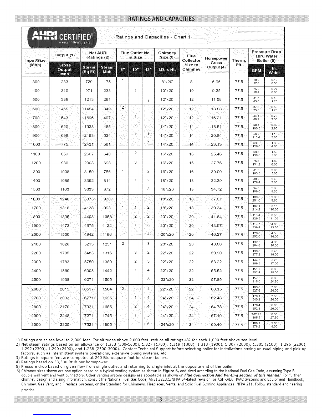
1) Ratings are at sea level to 2,000 feet. For altitudes above 2,000 feet, reduce all ratings 4% for each 1,000 feet above sea level
2) Net steam ratings based on an allowance of 1.333 (300-1600), 1.327 (1700), 1.319 (1800), 1.313 (1900), 1.307 (2000), 1.301 (2100), 1.296 (2200),
1.292 (2300), 1.290 (2400), and 1.288 (2500-3000). Contact Technical Support before selecting boiler for installations having unusual piping and pick-up
factors, such as intermittent system operations, extensive piping systems, etc.
3) Ratings in square feet are computed at 240 Btuh/square foot for steam boilers.
4) Ratings based on 33,500 Btuh per horsepower.
5) Pressure drop based on given flow from single outlet and returning to single inlet at the opposite end of the boiler.
6) Chimney sizes shown are one option based on a typical venting system as shown in Figure 6, and sized according to the National Fuel Gas Code, assuming Type B
double wall vent and vent connectors, Other venting system designs are acceptable as shown on Flue Connection And Venting section of this manual. For further
chimney design and sizing information, consult the National Fuel Gas Code, ANSI Z223.1/NFPA 54-latest revision, or ASHRAE6 HVAC Systems and Equipment Handbook,
Chimney, Gas Vent, and Fireplace Systems, or the Standard for Chimneys, Fireplaces, Vents, and Sotid Fuet Burning Appliances. NFPA 211. Follow standard engineering
practice.
20"x20' 20
22"x20' 22
22"x20' 22
22"x20' 22
22"x20 22
24"x20'
24'!x201
24,x20' 24
24'!x20 24
48.60
50.90
53.22
55.52
57.85
60ii5
62.48
64178
67:10
69,40
77.5
77.5
77.5
77.5
77.5
77 5
77.5
77.5
77.5
77:5
Page 4
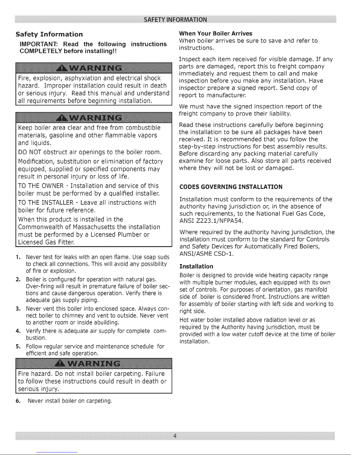
Safety Information
iMPORTANT: Read the following
COMPLETELY before installing!!
Fire, explosion, asphyxiation and electrical shock
instructions
hazard. Improper installation could result in death
or serious injury. Read this manual and understand
all requirements before beginning installation.
When Your Boiler Arrives
When boiler arrives be sure to save and refer to
instructions,
Inspect each item received for visible damage. If any
parts are damaged, report this to freight company
immediately and request them to call and make
inspection before you make any installation. Have
inspector prepare a signed report. Send copy of
report to manufacturer.
We must have the signed inspection report of the
freight company to prove their liability.
Keep boiler area clear and free from combustible
materials, gasoline and other flammable vapors
and liquids.
DO NOT obstruct air openings to the boiler room.
Modification, substitution or elimination of factory
equipped, supplied or specified components may
result in personal injury or loss of life.
TO THE OWNER = Tnstallation and service of this
boiler must be performed by a qualified installer.
TO THE INSTALLER = Leave all instructions with
boiler for future reference.
When this product is installed in the
Commonwealth of Massachusetts the installation
must be performed by a Licensed Plumber or
Licensed Gas Fitter.
1. Never test for leaks with an open flame, Use soap suds
to check all connections, This will avoid any possibility
of fire or explosion,
2. Boiler is configured for operation with natural gas,
Over-firing will result in premature failure of boiler sec-
tions and cause dangerous operation, Verify there is
adequate gas supply piping,
3. Never vent this boiler into enclosed space, Always con-
nect boiler to chimney and vent to outside, Never vent
to another room or inside abuilding,
4. Verify there is adequate air supply for complete com-
bustion,
5. Follow regular service and maintenance schedule for
efficient and safe operation,
Read these instructions carefully before beginning
the installation to be sure all packages have been
received. ]:t is recommended that you follow the
step=by=step instructions for best assembly results.
Before discarding any packing material carefully
examine for loose parts. Also store all parts received
where they will not be lost or damaged.
CODES GOVERNING INSTALLATION
Installation must conform to the requirements of the
authority having jurisdiction or, in the absence of
such requirements, to the National Fuel Gas Code,
ANSI Z223.1/NFPA54.
Where required by the authority having jurisdiction, the
installation must conform to the standard for Controls
and Safety Devices for Automatically Fired Boilers,
ANS_/ASME CSD=I,
Installation
Boiler is designed to provide wide heating capacity range
with multiple burner modules, each equipped with its own
set of controls. For purposes of orientation, gas manifold
side of boiler is considered front. Instructions are written
for assembly of boiler starting with left side and working to
right side.
Hot water boiler installed above radiation level or as
required by the Authority having jurisdiction, must be
provided with a low water cutoff device at the time of boiler
installation.
Fire hazard. Do not install boiler carpeting. Failure
to follow these instructions could result in death or
serious injury.
6. Never install boiler on carpeting.
Page 5
iiiiiiiiiiiiiiiiiiiiiiiiiiiiiiiiiiiiiiiiiiiiiiiiiiiiiiiiiiiiiiiiiiiiiiiiiiiiiiiiiiiiiiiiiiiiiiiiiiiiiiiiiiiiiiiiiiiiiiiiiiiiiiiiiiiiiiiiiiiiiiiiiiiiiiiiiiiiiiiiiiiiiiiiiiiiiiiiiiiiiiiiiiiiiiiiiiiiiiiiiiiiiiiiiiiiiiiiiiiiiiiiiiiiiiiiiiiiiiiiiiiiiiiiiiiiiiiiiiiiiiiiiiiiiiiiiiiiiiiiiiiiiiiiiiiiiiiiiiiiiiiiiiiiiiiiiiiiiiiiiiiiiiiiiiiiiiiiiiiiiiiiiiiiiiiiiiiiiiiiiiiiiiiiiiiiiiiiiiiiiiiiiiiiiiiiiiiiiiiiiiiiiiiiiiiiiiiiiiiiiiiiiiiiiiiiiiiiiiiiiiiiiiiiiiiiiiiiiiiiiiiiiiiiiiiiiiiiiiiiiiiiiiiiiiiiiiiiiiiiiiiiiiiiiiiiiiiiiiiiiiiiiiiiiiiiiiiiiiiiiiiiiiiiiiiiiiiiiiiiiiiiiiiiiiiiiiiiiiiiiiiiiiiiiiiiiiiiiiiiiiiiiiiiiiiiiiiiiiiiiiiiiiiiiiiiiiiiiiiiii_!i_I!E!__i!_i__i6_!_i_i_i_i_i_ii_i_ii_i_ii_i_i_iii!E_i_;E;il;Jl_ii_i_!!_il_iliiilililililil_iliiilililililil_iliiilililililil_iliiilililililil_iliiilililililil_iliiilililililil_iliiilililililil_iliiilililililil_iliiilililililil_iliiilililililil_iliiilililililil_iliiilililililil_iliiilililililil_iliiilililililil_iliiilililililil_iliiilililililil_iliiilililililil_iliiilililililil_iliiilililililil_iliiilililililil_iliiilililililil_iliiilililililil_iliiilililililil_iliiilililililil_iliiilililililil_iliiilililililil_iliiilililililil_iliiilililililil_iliiilililililil_iliiilililililil_iliiilililililil_iliiilililililil_iliiilililililil_iliiilililililil_iliiilililililil_iliiilililililil_iliiilililililil_iliiilililililil_iliiilililililil_iliiilii_
Boiler Location
Locate boiler on level, non=combustible foundation as near
to chimney or flue as possible. Allow 24 inches at front and
sides of boiler for servicing and cleaning. When installed in
utility room, the door should be wide enough to allow the
largest boiler parts to enter, or permit replacement of any
other appliance in the same room.
Tnstalling contractor must provide ventilated
foundation for boiler when installing:
• Over a room
• Over electrical wiring or cables of any kind
• Tf concrete floor is "green," or water is channeled
under concrete floor
Combustion Air
Provide combustion and ventilation air in accordance
with the section "Air for Combustion and Ventilation", of
the National Fuel Gas Code, ANSI Z223.1/NFPA 54, or
applicable provisions of the local building codes.
Chimney And Vent Pipe Connection
This is a very important part of the heating system. It must
be clean, the right size, properly constructed and in Good
Condition. No boiler can function properly with a bad
chimney. See Pages 6-::L0for specific venting instructions.
Flue pipe should be same size as draft hood outlet from boiler
to flue collector. See Chart 1 for Typical Chimney Size. Main-
rain a minimum upward slope of 1/4 inch per linear foot from
boiler to the chimney. Fasten joints together with sheet metal
screws to prevent sagging.
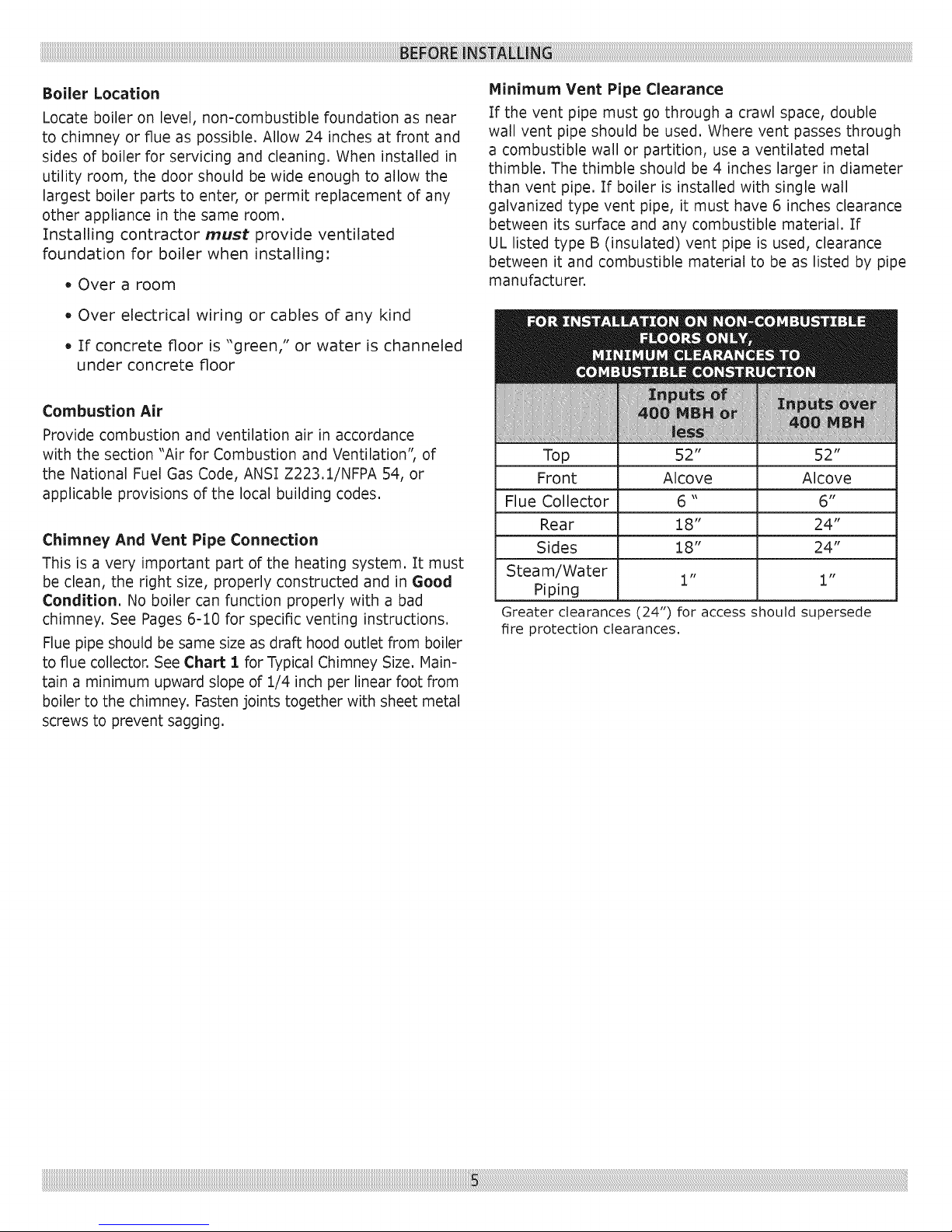
Minimum Vent Pipe Clearance
If the vent pipe must go through a crawl space, double
wall vent pipe should be used. Where vent passes through
a combustible wall or partition, use a ventilated metal
thimble. The thimble should be 4 inches larger in diameter
than vent pipe. If boiler is installed with single wall
galvanized type vent pipe, it must have 6 inches clearance
between its surface and any combustible material. If
UL listed type B (insulated) vent pipe is used, clearance
between it and combustible material to be as listed by pipe
manufacturer.
Top 52" 52"
Front Alcove Alcove
Flue Collector 6 " 6"
Rear 18" 24"
Sides 18" 24"
Steam/Water 1" 1"
Piping
Greater clearances (24") for access should supersede
fire protection clearances.
Page 6
iiiiiiiiiiiiiiiiiiiiiiiiiiiiiiiiiiiiiiiiiiiiiiiiiiiiiiiiiiiiiiiiiiiiiiiiiiiiiiiiiiiiiiiiiiiiiiiiiiiiiiiiiiiiiiiiiiiiiiiiiiiiiiiiiiiiiiiiiiiiiiiiiiiiiiiiiiiiiiiiiiiiiiiiiiiiiiiiiiiiiiiiiiiiiiiiiiiiiiiiiiiiiiiiiiiiiiiiiiiiiiiiiiiiiiiiiiiiiiiiiiiiiiiiiiiiiiiiiiiiiiiiiiiiiiiiiiiiiiiiiiiiiiiiiiiiiiiiiiiiiiiiiiiiiiiiiiiiiiiiiiiiiiiiiiiiiiiiiiiiiiiiiiiiiiiiiiiiiiiiiiiiiiiiiiiiiiiiiiiiiiiiiiiiiiiiiiiiiiiiiiiiiiiiiiiiiiiiiiiiiiiiiiiiiiiiiiiiiiiiiiiiiiiiiiiiiiiiiiiiiiiiiiiiiiiiiiiiiiiiiiiiiiiiiiiiiiiiiiiiiiiiiiiiiiiiiiiiiiiiii !! i!!!i i ! i ii !!L! i ii iii! ! i i i i i iJ i i! :!¸:! iiiiiiiili!i :!i611 !!i !ii! ii !i itli !ii!ii6!i iiiiii
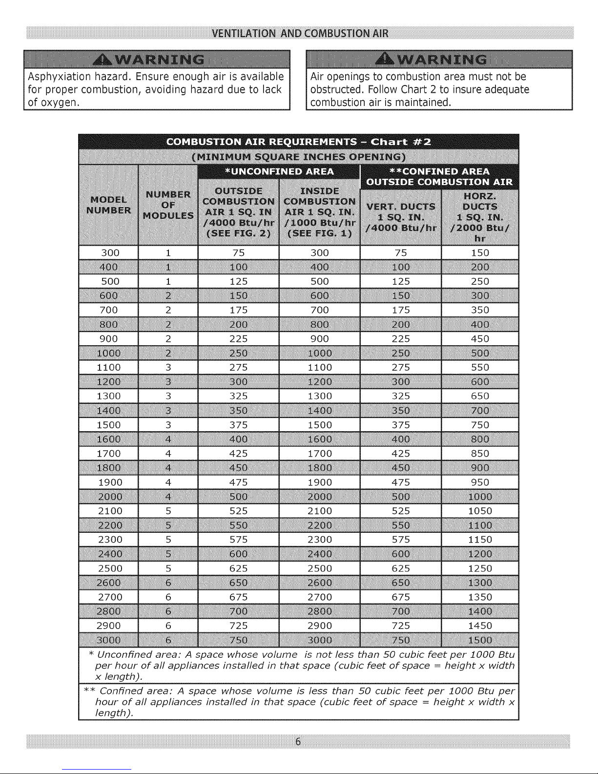
Asphyxiation hazard. Ensure enough air is available
for proper combustion, avoiding hazard due to lack
of oxygen.
300 i 75 300 75 150
500 i 125 500 125 250
700 2 175 700 175 350
900 2 225 900 225 450
ii!ii ii; i
1100 3 275 1100 275 550
Air openings to combustion area must not be
obstructed. Follow Chart 2 to insure adequate
combustion air is maintained.
1300 3 325 1300 325 650
1500 3 375 1500 375 750
1700 4 425 1700 425 850
1900 4 475 1900 475 950
2100 5 525 2100 525 1050
2300 5 575 2300 575 1150
2500 5 625 2500 625 1250
2700 6 675 2700 675 1350
2900 6 725 2900 725 1450
* Unconfined area: A space whose volume is not less than 50 cubic feetper 1000 Btu
per hour of all appliances installed in that space (cubic feet of space = height x width
x length).
** Confined area: A space whose volume is less than 50 cubic feet per 1000 Btu per
hour of all appliances installed in that space (cubic feet of space = height x width x
length).
Page 7
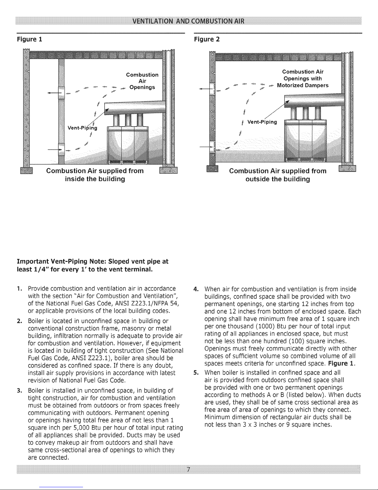
Figure I Figure 2
Combustion
Air
_ _, ODeninas
Y
f
Combustion Air supplied from
outside the building
Important Vent=Piping Note: Sloped vent pipe at
least 1/4" for every 1" to the vent terminal.
lo
Provide combustion and ventilation air in accordance
with the section "Air for Combustion and Ventilation",
of the National Fuel Gas Code, ANSI Z223.:[/NFPA 54,
or applicable provisions of the local building codes.
2o
Boiler is located in unconfined space in building or
conventional construction frame, masonry or metal
building, infiltration normally is adequate to provide a_r
for combustion and ventilation. However, if equipment
is located in building of tight construction (See National
Fuel Gas Code, ANSI Z223.:[), boiler area should be
considered as confined space. If there is any doubt,
install air supply provisions in accordance with latest
revision of National Fuel Gas Code.
3o
Boiler is installed in unconfined space, in building of
tight construction, air for combustion and ventilation
must be obtained from outdoors or from spaces freely
communicating with outdoors. Permanent opening
or openings having total free area of not less than 1
square inch per 5,000 Btu per hour of total input rating
of all appliances shall be provided. Ducts may be used
to convey makeup air from outdoors and shall have
same cross-sectional area of openings to which they
are connected.
4. When air for combustion and ventilation is from inside
buildings, confined space shall be provided with two
permanent openings, one starting 12 inches from top
and one 12 inches from bottom of enclosed space. Each
opening shall have minimum free area of 1 square inch
per one thousand (1000) Btu per hour of total input
rating of all appliances in enclosed space, but must
not be less than one hundred (100) square inches.
Openings must freely communicate directly with other
spaces of sufficient volume so combined volume of all
spaces meets criteria for unconfined space. Figure 1.
5. When boiler is installed in confined space and all
air is provided from outdoors confined space shall
be provided with one or two permanent openings
according to methods A or B (listed below). When ducts
are used, they shall be of same cross sectional area as
free area of area of openings to which they connect.
Minimum dimension of rectangular air ducts shall be
not less than 3 x 3 inches or 9 square inches.
Page 8
iiiiiiiiiiiiiiiiiiiiiiiiiiiiiiiiiiiiiiiiiiiiiiiiiiiiiiiiiiiiiiiiiiiiiiiiiiiiiiiiiiiiiiiiiiiiiiiiiiiiiiiiiiiiiiiiiiiiiiiiiiiiiiiiiiiiiiiiiiiiiiiiiiiiiiiiiiiiiiiiiiiiiiiiiiiiiiiiiiiiiiiiiiiiiiiiiiiiiiiiiiiiiiiiiiiiiiiiiiiiiiiiiiiiiiiiiiiiiiiiiiiiiiiiiiiiiiiiiiiiiiiiiiiiiiiiiiiiiiiiiiiiiiiiiiiiiiiiiiiiiiiiiiiiiiiiiiiiiiiiiiiiiiiiiiiiiiiiiiiiiiiiiiiiiiiiiiiiiiiiiiiiiiiiiiiiiiiiiiiiiiiiiiiiiiiiiiiiiiiiiiiiiiiiiiiiiiiiiiiiiiiiiiiiiiiiiiiiiiiiiiiiiiiiiiiiiiiiiiiiiiiiiiiiiiiiiiiiiiiiiiiiiiiiiiiiiiiiiiiiiiiiiiiiiiiiiiiiiiiiiiiiii_!i;_!ii!i_:i_i!i!ii_ilL!i!i_i_!iiiiiii!_ii!i_iilililili:ii!iili_i_i_:!_:i_!ii!i_!ii!ii!_i!i_ii_i_ii:!_!i_!_:i!i_!i!!_!iJliill_iii!i_iililili_!illjiiii!_:i_:iiiiiiiiiiiiiiiiiiiiiiiiiiiiiiiiiiiiiiiiiiiiiiiiiiiiiiiiiiiiiiiiiiiiiiiiiiiiiiiiiiiiiiiiiiiiiiiiiiiiiiiiiiiiiiiiiiiiiiiiiiiiiiiiiiiiiiiiiiiiiiiiiiiiiiiiiiiiiiiiiiiiiiiiiiiiiiiiiiiiiiiiiiiiiiiiiiiiiiiiiiiiiiiiiiiiiiiiiiiiiiiiiiiiiiiiiiiiiiiiiiiiiiiiiiiiiiiiiiiiiiiiiiiiiiiiiiiiiiiiiiiiiiiiiiiiiiiiiiiiiiiiiiiiiiiiiiiiiiiiiiiiiiiiiiiiiiiiiiiiiiiiiiiiiiiiiiiiiiiiiiiiiiiiiiiiiiiiiiiiiiiiiiiiiiiiiiiiiiiiiiiiiiiiiiiiiiiiiiiiiiiiiiiiiiiiiiiiiiiiiiiiiiiiiiiiiiiiiiiiiiiiiiiiiiiiiiiiiiiiiiiiiiiiiiiiiiiiiiiiiiiiiiiiiiiiiiiiiiiiiiiiiiiiiiiiiiiiiiiiiiiiiiiiiiiiiiiiiiiiiiiiiiiiiiiiiiiiiiiiiiiiiiiiiiiiiiiiiiiiiiiiiiiiiiiiiiiiiiiiiiiiiiiiiiiiiiiiiiiiiiiiiiiiiiiiiiiiiiiiiiiiiiiiiiiiiiiiiiiiiiiiiiiii:_:_:_i_i_i_i_i_i_ii_ii_ii_ii_ii_ii_ii_ii_ii_ii_ii_ii_ii_ii_ii_ii_ii_i_i:i_i:i!iiiiii
A. When installing two openings, one must commence B.
within 12 inches from top and other within 12
inches from bottom of enclosure. Openings shall
communicate directly, or by ducts, with outdoors
or spaces (:crawl or attic) that freely communicate
with outdoors. One of following methods must be
used to provide adequate air for ventilation and
combustion.
1) When directly communicating with outdoors,
each opening shall have minimum free area of
1 square inch per 4,000 Btu per hour of total
input rating of all equipment in enclosure. Refer
to Figure 2 on previous page.
2) When communicating with outdoors by
means of vertical ducts, each opening shall
have minimum free area 1 square inch per
4,000 Btu per hour of total input rating of all
appliances in the enclosed space.
3) If horizontal ducts are used, each opening
and duct shall have minimum free area 1
square inch per 2,000 Btu per hour of total
input rating of all appliances in the enclosed
space.
.
In calculating free area using louvers, grilles or
screens for above, consideration shall be given
to their blocking effect. Screens used shall not be
smaller than 1/4 inch mesh. If free area through
design of louver or grill is known, it should be used
in calculating size opening required to provide free
area specified. If design and free area is not known,
it may be assumed that wood louvers will have 20=
25% free area and metal louvers and grilles will
have 60-75% free area. Louvers and grilles should
be fixed in open position or interlocked with boiler
so they are opened automatically during boiler
operation.
One permanent opening, commencing within 12
inches of top of enclosure, shall be permitted where
equipment has clearances of at least 1 inch from
sides, 1 inch from back, and 6 inches from front
of boiler. Opening shall directly communicate with
outdoors or shall communicate through vertical
or horizontal duct to outdoors or spaces (:crawl
or attic) that freely communicate with outdoors.
Openings must have minimum free area of 1
square inch per 3000 Btu per hour of total input
rating of all equipment located in enclosure. Free
area must be no less than sum of areas of all vent
connectors in confined space.
iiiiiiiiiiiiiiiiiiiiiiiiiiiiiiiiiiiiiiiiiiiiiiiiiiiiiiiiiiiiiiiiiiiiiiiiiiiiiiiiiiiiiiiiiiiiiiiiiiiiiiiiiiiiiiiiiiiiiiiiiiiiiiiiiiiiiiiiiiiiiiiiiiiiiiiiiiiiiiiiiiiiiiiiiiiiiiiiiiiiiiiiiiiiiiiiiiiiiiiiiiiiiiiiiiiiiiiiiiiiiiiiiiiiiiiiiiiiiiiiiiiiiiiiiiiiiiiiiiiiiiiiiiiiiiiiiiiiiiiiiiiiiiiiiiiiiiiiiiiiiiiiiiiiiiiiiiiiiiiiiiiiiiiiiiiiiiiiiiiiiiiiiiiiiiiiiiiiiiiiiiiiiiiiiiiiiiiiiiiiiiiiiiiiiiiiiiiiiiiiiiiiiiiiiiiiiiiiiiiiiiiiiiiiiiiiiiiiiiiiiiiiiiiiiiiiiiiiiiiiiiiiiiiiiiiiiiiiiiiiiiiiiiiiiiiiiiiiiiiiiiiiiiiiiiiiiiiiiiiiiiiiiiiiiiiiiiiiiiiiiiiiiiiiiiiiiiiiiiiiiiiiiiiiiiiiiiiiiiiiiiiiiiiiiiiiiiiiiiiiiiiiiiiiiiiiiiiiiiiiiiiiiiiiiiiiiiiiU_!i_i!!_ii_iiiiiiiJ!iii_iii_!_i_ii!_ii!iL!_ii_iim:i:i!_ii_illii¸iiiiiiii¸iiiiiiii¸iiiiiiii¸iiiiiiii¸iiiiiiii¸iiiiiiii¸iiiiiiii¸iiiiiiii¸iiiiiiii¸iiiiiiii¸iiiiiiii¸iiiiiiii¸iiiiiiii¸iiiiiiii¸iiiiiiii¸iiiiiiii¸iiiiiiii¸iiiiiiii¸iiiiiiii¸iiiiiiii¸iiiiiiii¸iiiiiiii¸iiiiiiii¸iiiiiiii¸iiiiiiii¸iiiiiiii¸iiiiiiii¸iiiiiiii¸iiiiiiii¸iiiiiiii¸iiiiiiii¸iiiiiiii¸iiiiiiii¸iiiiiiii¸iiiiiiii¸iiiiiiii¸iiiiiiii¸iiiiiiii¸iiiiiiii,,
Vent connectors serving appliances vented by
natural draft shall not be connected into any
portion of mechanical draft systems operating
under positive pressure.
4_
1. The vent pipe must slope upward from the boiler
not less than 1/4" for every 1' to the vent terminal.
Figures 1 & 2,
2. Horizontal portions of the venting system shall be
supported rigidly every 5 feet and at the elbows. No
portion of the vent pipe should have dips or sags.
Flue Connection And Venting
Vent installations shall be in accordance with "Venting of
Equipment", of the National Fuel Gas Code, ANSI Z223.1/
NFPA 54, or applicable provisions of the local building
codes.
1. Consult dimensional drawing for number and size of
flue pipes required for each size boiler.
2. Maintain minimum upward slope of 1/4 inch per linear
foot from the boiler to chimney.
3. Run flue pipe directly as possible. Keep turns to a
minimum. Insert flue pipe into, but not beyond, inside
wall of chimney. Do not connect into a chimney serving
an open fireplace.
Insulate flue pipe where it passes near combustible
material.
5.
Rigidly support pipe with hangers and straps.
6.
Extend chimneys at least 2 feet above any object
within radius of 15 feet, including roof.
7.
Install hood on all flue pipes which extend through roof.
In most locations, venting of boiler relies on natural
draft. In as much as energy available from natural
draft is quite low, serious thought should be given to
vent system design, i.e., adequate size, use of gradual
transitions, tees, elbows, etc., close proximity of boiler
and chimney. On all boilers, vertical risers must be at
least as large as vent openings on draft=hood. Boiler
manufacturer makes no specific recommendations
regarding application of draft inducers that may be
used with this boiler. If draft inducer is used, it is up to
installing contractor and draft inducer manufacturer to
determine proper application.
Page 9
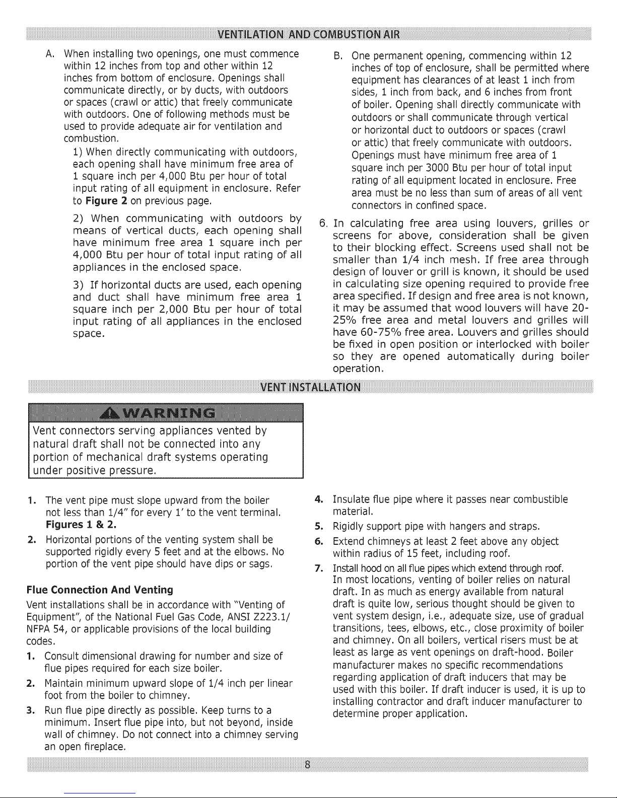
Flue Connection And Venting - Continued
Simple vent system consists of 6-foot minimum vertical
rise immediately off draft-hood, as shown in Figure 3.
Terminate this vertical flue above building roof with suitable
rain cap at least 2 feet above surrounding obstructions,
i.e., parapets, adjacent buildings, penthouses, etc. This
type of vent system applies to single draft-hood boilers
ONLY, and has limited practical use, because it is restricted
to single-story boiler rooms and because of problems
encountered in roof flashing.
Vertical venting system shown in Figure 3 cannot be used
on multiple=base boilers because of physical interference of
multiple rain caps.
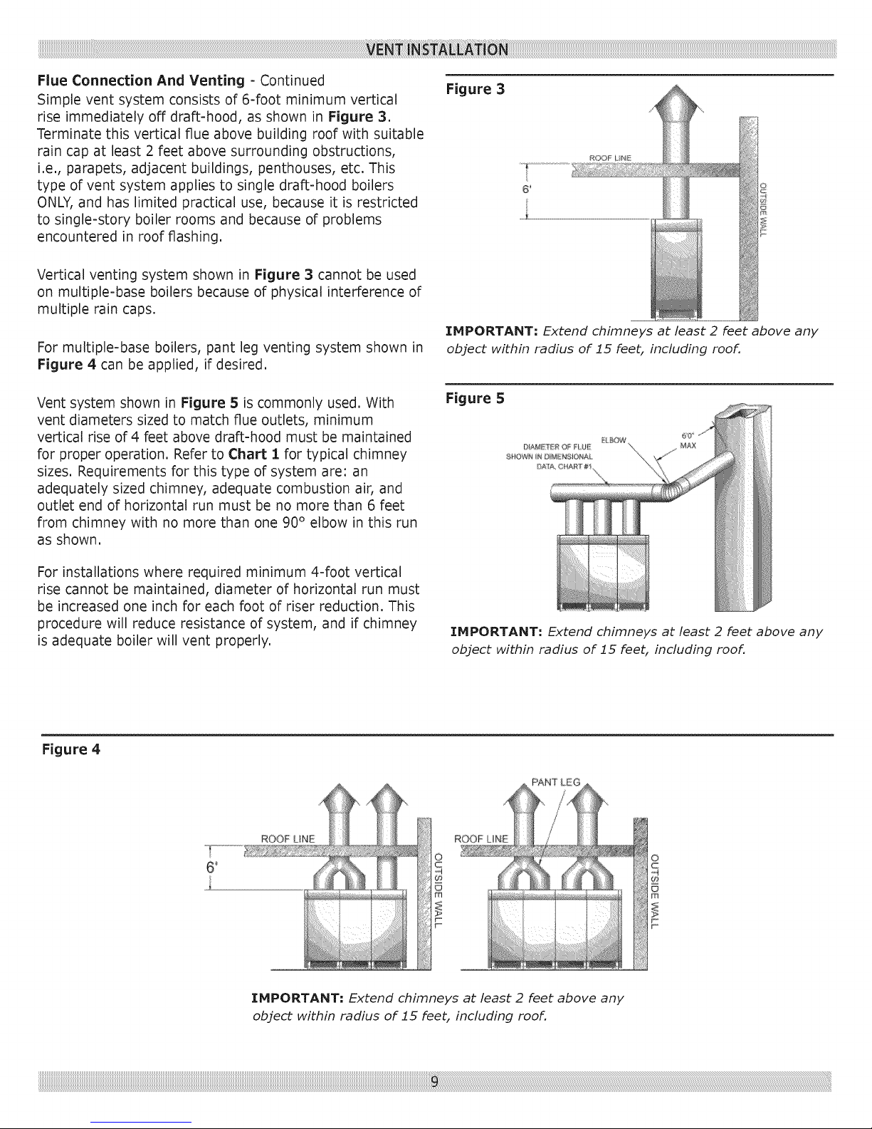
For multiple=base boilers, pant leg venting system shown in
Figure 4 can be applied, if desired.
Figure 3
IMPORTANT: Extend chimneys at least 2 feet above any
object within radius of 15 feet, including roof.
Vent system shown in Figure 5 is commonly used. With
vent diameters sized to match flue outlets, minimum
vertical rise of 4 feet above draft=hood must be maintained
for proper operation. Refer to Chart 1 for typical chimney
sizes. Requirements for this type of system are: an
adequately sized chimney, adequate combustion air, and
outlet end of horizontal run must be no more than 6 feet
from chimney with no more than one 90° elbow in this run
as shown.
For installations where required minimum 4-foot vertical
rise cannot be maintained, diameter of horizontal run must
be increased one inch for each foot of riser reduction. This
procedure will reduce resistance of system, and if chimney
is adequate boiler will vent properly.
Figure 4
Figure 5
IMPORTANT: Extend chimneys at least 2 feet above any
object within radius of 15 feet, including roof.
_
IMPORTANT: Extend chimneys at least 2 feetabove any
object within radius of 15 feet, including roof.
ii
Page 10
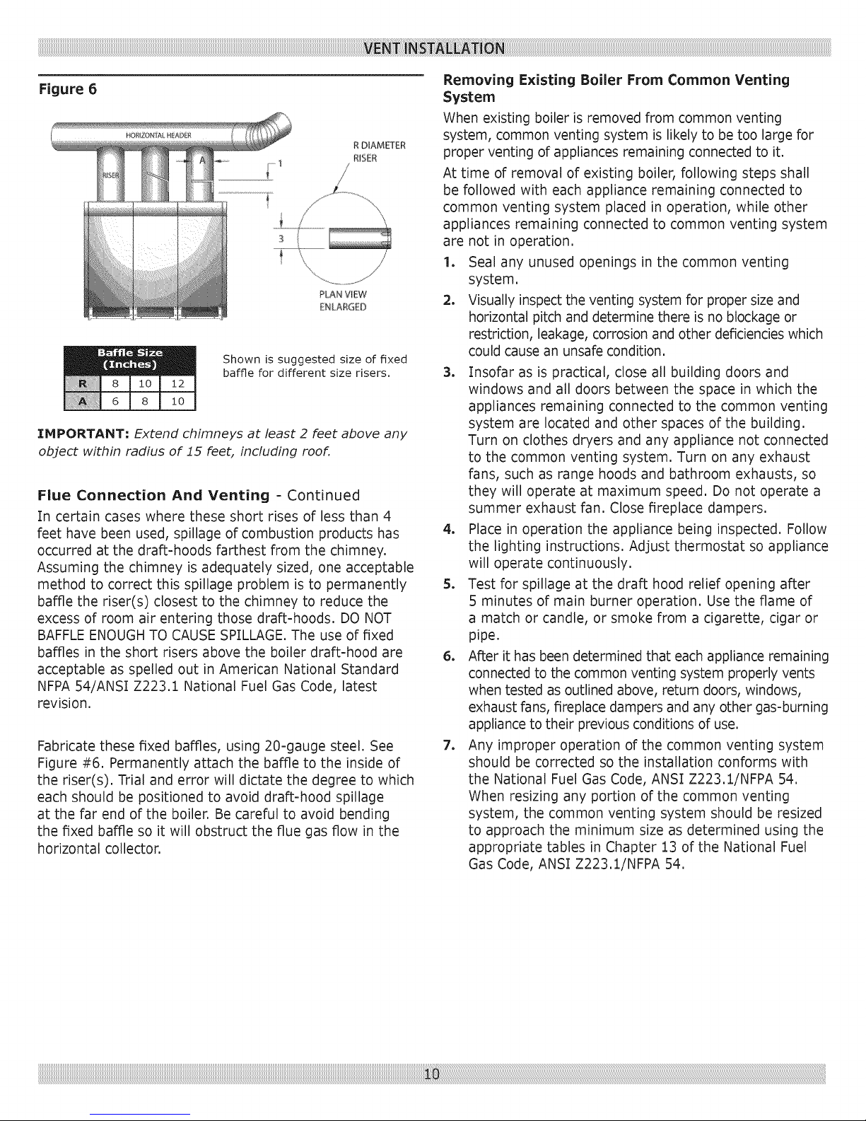
Figure 6
Shown is suggested size of fixed
baffle for different size risers.
IMPORTANT; Extend chimneys at least 2 feet above any
object within radius of 15 feet, including roof.
Flue Connection And Venting = Continued
In certain cases where these short rises of less than 4
feet have been used, spillage of combustion products has
occurred at the draft-hoods farthest from the chimney.
Assuming the chimney is adequately sized, one acceptable
method to correct this spillage problem is to permanently
baffle the riser(s) closest to the chimney to reduce the
excess of room air entering those draft-hoods. DO NOT
BAFFLE ENOUGH TO CAUSE SPILLAGE. The use of fixed
baffles in the short risers above the boiler draft-hood are
acceptable as spelled out in American National Standard
NFPA 54/ANSI Z223.1 National Fuel Gas Code, latest
revision.
Fabricate these fixed baffles, using 20-gauge steel. See
Figure #6. Permanently attach the baffle to the inside of
the riser(s). Trial and error will dictate the degree to which
each should be positioned to avoid draft-hood spillage
at the far end of the boiler. Be careful to avoid bending
the fixed baffle so it will obstruct the flue gas flow in the
horizontal collector.
Removing Existing Boiler From Common Venting
System
When existing boiler is removed from common venting
system, common venting system is likely to be too large for
proper venting of appliances remaining connected to it.
At time of removal of existing boiler, following steps shall
be followed with each appliance remaining connected to
common venting system placed in operation, while other
appliances remaining connected to common venting system
are not in operation.
1. Seal any unused openings in the common venting
system.
2. Visually inspect the venting system for proper size and
horizontal pitch and determine there is no blockage or
restriction, leakage, corrosion and other deficiencies which
could cause an unsafe condition.
3. Insofar as is practical, close all building doors and
windows and all doors between the space in which the
appliances remaining connected to the common venting
system are located and other spaces of the building.
Turn on clothes dryers and any appliance not connected
to the common venting system. Turn on any exhaust
fans, such as range hoods and bathroom exhausts, so
they will operate at maximum speed. Do not operate a
summer exhaust fan. Close fireplace dampers.
4. Place in operation the appliance being inspected. Follow
the lighting instructions. Adjust thermostat so appliance
will operate continuously.
5. Test for spillage at the draft hood relief opening after
5 minutes of main burner operation. Use the flame of
a match or candle, or smoke from a cigarette, cigar or
pipe.
6. After it has been determined that each appliance remaining
connected to the common venting system properly vents
when tested as outlined above, return doors, windows,
exhaust fans, fireplace dampers and any other gas-burning
appliance to their previous conditions of use.
7. Any improper operation of the common venting system
should be corrected so the installation conforms with
the National Fuel Gas Code, ANSI Z223.1/NFPA 54.
When resizing any portion of the common venting
system, the common venting system should be resized
to approach the minimum size as determined using the
appropriate tables in Chapter 13 of the National Fuel
Gas Code, ANSI Z223.1/NFPA 54.
Page 11

iiiiiiiiiiiiiiiiiiiiiiiiiiiiiiiiiiiiiiiiiiiiiiiiiiiiiiiiiiiiiiiiiiiiiiiiiiiiiiiiiiiiiiiiiiiiiiiiiiiiiiiiiiiiiiiiiiiiiiiiiiiiiiiiiiiiiiiiiiiiiiiiiiiiiiiiiiiiiiiiiiiiiiiiiiiiiiiiiiiiiiiiiiiiiiiiiiiiiiiiiiiiiiiiiiiiiiiiiiiiiiiiiiiiiiiiiiiiiiiiiiiiiiiiiiiiiiiiiiiiiiiiiiiiiiiiiiiiiiiiiiiiiiiiiiiiiiiiiiiiiiiiiiiiiiiiiiiiiiiiiiiiiiiiiiiiiiiiiiiiiiiiiiiiiiiiiiiiiiiiiiiiiiiiiiiiiiiiiiiiiiiiiiiiiiiiiiiiiiiiiiiiiiiiiiiiiiiiiiiiiiiiiiiiiiiiiiiiiiiiiiiiiiiiiiiiiiiiiiiiiiiiiiiiiiiiiiiiiiiiiiiiiiiiiiiiiiiiiiiiiiiiiiiiiiiiiiiiiiiiiiiiiiiiiiiiiiiiiiiiiiiiiiiiiiiiiiiiiiiiiiiiiiiiiiiiiiiiiiiiiiiiiiiiiiiiiiiiiiiiiiiiiiiiiiiiiiiiiiiiiiiiiiiiiiiiiiiiiiiili¸ii_iiii6!ili!iil;Lili_!i!ii_iiiiil;!i!iii_i_lii!;ii_i!i!_!!_i_iii_!iiiiii!!i_ii_i_iii_i_ii_ii_ii_ii_ii_ii_ii_ii_ii_ii_ii_ii_ii_ii_ii_ii_ii_ii_ii_ii_ii_ii_ii_ii_ii_ii_ii_ii_ii_ii_ii_ii_ii_ii_ii_ii_ii_ii_ii_ii_ii_ii_ii_ii_ii_ii_ii_ii_ii_ii_ii_ii_ii_ii_ii_ii_ii_ii_ii_ii_ii_ii_ii_ii_ii_ii_ii_ii_ii_ii_ii_ii_ii_ii_ii_ii_ii_ii_ii_ii_ii_ii_ii_ii_ii_ii_ii_ii_ii_ii_ii_ii_ii_ii_ii_ii_ii_ii_ii_ii_ii_ii_ii_ii_ii_ii_ii_ii_ii_ii_ii_ii_ii_ii_ii_ii_ii_ii_ii_ii_ii_ii_ii_ii_ii_ii_ii_ii_ii_ii_ii_ii_ii_ii_ii_ii_ii_ii_ii_ii_ii_ii_ii_ii_ii_ii_ii_ii_ii_ii_ii_ii_ii_ii_ii_ii_ii_ii_ii_ii_ii_ii_ii_ii_ii_ii_ii_ii_ii_ii_ii_ii_ii_ii_ii_ii_ii_ii_ii_ii_ii_ii_ii_ii_ii_ii_ii_ii_ii_ii_ii_ii_ii_ii_ii_ii_ii_ii_ii_ii_ii_ii_ii_ii_ii_ii_ii_ii_ii_ii_ii_ii_ii_ii_ii_ii_ii_ii_ii_ii_ii_ii_ii_ii_ii_ii_ii_ii_ii_ii_ii_ii_ii_ii_ii_ii_ii_ii_ii_ii_ii_ii_ii_ii_ii_ii_ii_ii_ii_ii_ii_ii_ii_ii_ii_ii_ii_ii_ii_ii_ii_ii_ii_ii_ii_ii_ii_ii_ii_ii_ii_ii_ii_ii_ii_ii_ii_ii_ii_ii_ii_ii_ii_ii_ii_ii_ii_ii_ii_ii_ii_ii_ii_ii_ii_ii_ii_ii_ii_ii_ii_ii_ii_ii_ii_ii_ii_ii_ii_ii_ii_ii_ii_ii_ii_ii:i!ii
Front View Left Side View
Su
38"
h AA
Top View
C D E F G H
Returr)
Supply
Floor Line
A
Flue Nutlets
ALL SUPPLY AND RETURN
CONNECTIONS ARE 4 INCH
>ply
Page 12

Base Assembly
The 300, 400 and 500 boilers are the basic models. The 300
model has (6) burners, the 400 model has (8) burners and
the 500 model has (10) burners. Combinations of the basic
models are used to assemble the 600 through 3000 models.
Refer to Chart 3 for the proper order of assembly. When two
or more bases are used to assemble the boiler, be sure the
tops of the bases are even.
The bases are fastened together with 5/16 cap bolts and
nuts. [nsert two bolts in the front posts and two in the rear
posts as shown in Figure 7A. After bases are fastened
together, install the base end panels. These end panels
must be installed before assembling sections Figure 7B.
Section Assembly
The sections may be started from either the left or right end
of the base.
Place the end section on the base with the center-line of the
section directly over the joint of the base end closure. With boilers
having two or more bases, as you progress be sure the parting
line (center-line of section) of the intermediate sections fall on
the junction of the two bases. Figure 8.
Figure 8
Important: After bases are assembled check to be sure
they are level.
Figure 7B
Bolts with nuts in
oosts
Center-line
of section
Base joint
Before beginning, clean nipples and nipple ports. Coat
nipples and nipple ports with pipe joint compound
or other good sealant and keep them clean. Figure
9.
Figure 9
/I
iiiiiiiii!iiiii!!!!_;_,
Figure 10
!i!i!i!i!i!i!i!i!i!i!i!i!i!i!i!i!i!i!i!i!i!i!i!i!i!i!i!i!i!i!i!i!i!i!i!i!i!i!i!i!i!i!i!i!i!i!i!i!i!i!i!i!i!i!i!i!i!i!i!i!i!i!i!i!i!i!i!i!i!i!i!i!i!i!i!i!i!i!i!i!i!i!i!i!i!i!i!i!i!i!i!i!i!i!i!i!i!i!i!i!i!i!i!i!i!i!i!i!i!i!i!i!i!i!i!i!i!i!i!i!i!i!i!i!i!i!i!i!i!i!i!i!i!i!i!i!i!i!i!i!i!i!i!i!i!i!i!i!i!i!i!i!i!i!i!i!i!i!i!i!i!i!i!i!i!i!i!i!i!i!i!i!i!i!i!i!i!i!i!i!i!i!i!i!i!i!i!i!i!i!i!i!i!i!i!i!i!i!i!i!i!i!i!i!i!i!i!i!i!i!i!i!i!i!i!i!i!i!i!i!i!i!i!i!i!i!i!i!i!i!i!i!i!i!i!i!i!i!i!i!i!i!i!i!i!i!i!i!i!i!i!i!i!i!i!i!i!i!i!i!i!i!i!i!i!i!i!i!i!i!i!i!i!i!i!i!i!i!i!i!i!i!i!i!i!i!i!i!i!i!i!i!i!i!i!i!i!i!i!i!i!i!i!i!i!i!i!i!i!i!i!i!i!i!i!i!i!i!i!i!i!i!i!i!i!i!i!i!i!i!i!i!i!i!i!i!i!i!i!i!i!i!i!i!i!i!i!i!i!i!i!i!i!i!i!i!i!i!i!i!i!i!i!i!i!i!i!i!i!i!i!i!i!i!i!i!i!i!i!_¸!i_!i_!i_!i_!i_!i_!i_!i_!i_!i_!i_!i_!i_!i_!i_!i_!i_!i_!i_!i_!i_!i_!i_!i_!i_!i_!i_!i_!i_!i_!i_!i_!i_!i_!i_!i_!i_!i_!i_!i_!i_!i_!i_!i_!i_!i_!i_!i_!i_!i_!i_!i_!i_!i_!i_!i_!i_!i_!i_!i_!i_!i_!i_!i_!i_!i_!i_!i_!i_!i_!i_!i_!i_!i_!i_!i_!i_!i_!i_!i_!i_!i_!i_!i_!i_!i_!i_!i_!i_!i_!i_!i_!i_!i_!i_!i_!i_!i_!i_!i_!i_!i_!i_!i_!i_!i_!i_!i_!i_!i_!i_!i_!i_!i_!i_!i_!i_!i_!i_!i_!i_!i_!i_!i_!i_!i_!i_!i_!i_!i_!i_!i_!i_!i_!i_!i_!i_!i_!i_!i_!i_!i_!i_!i_!i_!i_!i_!i_!i_!i_!i_!i_!i_!i_!i_!i_!i_!i_!i_!i_!i_!i_!i_!i_!i_!i_!i_!i_!i_!i_!i_!i_!i_!i_!i_!i_!i_!i_!i_!i_!i_!i_!i_!i_!i_!i_!i_!i_!i_!i_!i_!i_!i_!i_!i_!i_!i_!i_!i_!i_!i_!i_!i_!i_!i_!i_!i_!i_!i_!i_!i_!i_!i_!i_!i_!i_!i_!i_!i_!i_!i_!i_!i_!i_!i_!i_!i_!i_!i_!i_!i_!i_!i_!i_!i_!i_!i_!i_!i_!i_!i_!i_!i_!i_!i_!i_!i_!i_!i_!i_!i_!i_!i_!i_!i_!i_!i_!i_!i_!i_!i_!i_!i_!i_!i_!i_!i_!i_!i_!i_!i_!i_!i_!i_!i_!i_!i_!i_!i_!i_!i_!i_!i_!i_!i_!i_!i_!i_!i_!i_!i_!i_!i_!i_!i_!i_!i_!i_!i_!i_!i_!i_!i_!i_!i_!i_!i_!i_!i_!i_!i_!i_!i_!i_!i_!i_!i_!i_!i_!i_!i_!i_!i_!i_!i_!i_!i_!i_!i_!i_!i_!i_!i_!i_!i_!i_!i_!i_!i_!i_!i_!i_!i_!i_!i_!i_!i_!i_!i_!i_!i_!i_!i_!i_!i_!i_!i_!i_!i_!i_!i_!i_!i_!i_!i_!i_!i_!i_!i_!i_!i_!i_!i_!i_!i_!i_!i_!i_!!:_ii!
Page 13

Place nipples in ports taking care to seat them squarely to
prevent cocking. Figure 10.
When pulling sections together with tie rods, always insert
tie rods in holes nearest to nipple ports. Hove tie rods to
proper location, if necessary, only after sections are fully
pulled together. Oil or lubricate threads, insert tie rods
in lugs with washers under nuts and tighten uniformly
and evenly so that sections are pulled parallel as they go
together. When all sections are pulled up locate tie rods in
alternating pairs of upper and lower holes between adjacent
sections. Figure 11.
Be sure both ends of completed section assembly are
resting evenly on both ends of base.
Apply furnace cement at the joints of the sections front, top
and back. Putty should also be applied where the sections
join the base. Figure 12.
Place necessary plugs and control wells in correct locations.
Plug all other tappings, leaving air vent in top of one of
end sections, and connect water. Fill boiler with water
until it runs out the air vent. Hydrostatically test boiler in
accordance with applicable codes. Check for leaks before
continuing with assembly Drain and remove unnecessary
plugs.
Attaching Draft Hoods
Attach the draft hoods to the boiler sections after
applying boiler putty to the top of the boiler sections
where the hoods and sections meet. Use j=bolts to
attach the fronts of the draft hoods to slots in the
section flanges. Figure 13.
Figure 13
Draft hood notched
to fit over sections
g-bolt & nut
attach to front
of hood
Figure 11
Draft hood
covers
Apply turnace cement to joints on all sides or DOller.
Page 14

Installing Boiler 3acket Panels
NOTE: Jacket assembly must start at the left side of boiler,
1. Attach lower jacket end panel (left) to two Z=bars on
base end closures through two slotted holes on bottom
of jacket end panel, Use (2) #10 x 1/2"screws, Figure
14,
2. Attach middle jacket end panel (left) to lower jacket
end panel with middle laying over lower and lining up
holes, Use (5) #10 x 1/2"screws, Figure 1S.
3. Attach upper jacket end panel (left) to middle jacket
end panel with upper behind middle and lining up holes,
Use (6) #10 x 1/2"screws, Ensure bare metal plate is
inserted between casting ridge and draft hood, This will
hold panel in place, Figure 16.
4. Position top/front intermediate panel so back edge of top
hangs on adjustable clips on front of draft hood(s); left
edge hangs on bracket on left upper jacket end panel;
and right edge with integral bracket hangs on tie rod(s),
Figure 17,
5. Attach top/front intermediate panel to lower base
brackets through four slotted holes in panel, Use (4)
#10 x 1/2"screws, Figure 18.
6. On multiple base boilers, each additional top/front
intermediate panel attaches in same way (working your
way from left to right), Figure 19.
Figure 16
Figure 17
Adjustable Clip,.
Bracket
Page 15

Installing Boiler Jacket Panels - Continued
7. Attach upper jacket end panel (right) so left edge hangs
on bracket on top/front intermediate panel. Insert bare
metal plate in same manner as left panel Figure 20.
8. Attach middle jacket end panel (right) to upper jacket
end panel with middle laying over upper and tining up
holes. Use (6) #I0 x l/a" screws. Figure 21.
9. Attach lower jacket end panel (right) to middle jacket
end panel with lower behind middle and lining up holes.
Use (5) #!0 x 1if, screws, Attach lower jacket end
panel to two Z-bars on base end closures through two
slotted holes on bottom of jacket end panel. Use (2)
#10 x 1/2"screws. Figure 21B.
10. Position top of rear jacket panel(s) to draft hood baffle
flange and secure with (2) #10 x l/f, screws. Secure
bottom of rearjacket panel(s) to bracket(s) on boiler
base using (2) #10 x 1ia"screws. Figure 22.
Installing Boiler .lacket Panels - Continued
Figure 18
Figure 20
Figure 19
Figure 21A ....
Page 16

11. Attach burner door knobs with #8-32 x 1/4"screws and
#8-32 hex nuts, Slide bottom of lower access door(s)
in slots on top of manifold brackets, Figure 23,
12. Position control access jacket panel(s) so tabs slide into
slots on top/front intermediate jacket panel(s), Attach
control access jacket panel to top/front intermediate
jacket, Use (2) #10 x 1/2"screws, Figure 24,
13. Lighting Instruction Plates are provided with each
Figure 21B
boiler base. Each boiler base also includes data plate
indicating required gas type, firing rate, and gas
pressure for that base. These plates are located on
Jacket Top/Front Panels. Boilers also have rating plate
showing total Input and Output Ratings. This rating
plate is shipped in AC Carton and is to be mounted on
side Jacket End Panel by installing contractor.
14. Attach Local Code Label (not provided by
manufacturer.)
Figure 23
Figure :24
Figure 22
NOTE: The attachment of the control access jacket
panels can wait until the controls have been mounted
to the top/front intermediate jacket panels.
Page 17

Control Mounting And Installation
NOTE: Electrical controls (j-box, transformer, etc. can
be mounted on either left or right jacket end panel.
Subsequently, boiler safeties (LWCO, etc.) and their
respective piping must be mounted on opposite end of
boiler.
1. Attach j-box assembly to jacket end panel aligning with
holes in end panel, Use (4) #10 x 1/2"screws, Figure
25A,
2. Position harness and plug from j-box through opening
in jacket end panel. Figure 25B.
3. Boilers with four through six bases, require transformer
mounted externally to j-box assembly. Attach
transformer and bracket assembly to jacket end panel by
using #10 x 1/2"screws; (3) along top of bracket and (2)
along lower edge of bracket. Figure 26A. Remove cover
(2 screws) from ]-box, then remove knockout (left or
right side). Connect plug of harness from transformer to
plug on j-box. Figure 26B.
Figure 25A
4. Orient harness of control panel assembly so correct
(female) plug is toward j-box and will connect to
j-box harness. Figure 27A. Secure harness to control
panel with zip=ties and #10 x I/2" screws. Figure 27A,
Connect plugs on harnesses. Figure 27B.
5. Attach control panel to intermediate jacket panel
aligning with holes. Use (4) #10 x I/2" screws. Connect
plugs on control panel to j-box. Figure 28,
6. On multiple base boilers, mount remaining control
panels to intermediate jacket panels following steps 4
&5.
7. On each base, connect gas valve harness and pilot
spark wire to control. Figures 29A & 29B.
Figure 26A
Figure 26B
Page 18

Control Mounting And Installation
Figure 27A Figure 29A
Figure 27B
Figure 28
Figure 29B
Page 19

Illustration shows the end section and the various tap-
pings provided. Tappings are the same in both right
and left end sections.
Emml
Figure 29
F
A 4" Supply and Return Supply and
B 1/2" Gauge Glass Set
C 3/4" Drain, Left End
C 314" Drain, Right End Drain, Right
D 1/2" Plugged trol
E 1" Accessories Accessories
*F 1" Safety Valve Valve
G 3/4. Plugged or Electronic
*If openirlg F is to be used for something other than
the Safety Valve or Safety Relief Valve, or the Safety/
Relief valve is larger than 1", the Safety/Relief Valve
must be installed in the Header Piping as near the
boiler as possible
Primary LWCO and Plugged
(Probe Type) LWCO Plugged
Return
Drain, Left
End
End
Limit Con-
Safety Relief
Following controls are supplied as standard equipment.
Details of their function and operation will be found in
section on Controls and Adjustments.
C
Figure 30
B
G
B
A
E
1. Water temperature high limit control
2. Combination temperature = pressure gauge
3. Safety relief valve (30 psi)
WATER TRIM ASSEMBL Y
Locate water trim controls per chart and illustration
above.
1. Low Water Cut-Off (mounted externally) with blow-off
valve
2. High Pressure Limit Control
3. Pressure Gauge
4. Water Gauge Glass Set
5. Siphon Loop
6. Safety Valve (i5 psi..)
Assemble Steam Trim, Low Water Cut=Off, High
Pressure Limit Control, Pressure Gauge, Water Gauge
Glass Set and Siphon Loop, as shown in Figures
30. See Illustration and Chart above for location of
controls.
LO0_
CUT OF
NOTE:
WATER LEVEL
29"TO FLOOR
No shutoff of any description shall be placed between
the pressure relief valve and the boiler, or on discharge
pipes between such safety valves and the atmosphere.
Installation of the pressure relief valve shall conform
to the requirements of the ANSI/ASME Boiler and
Pressure Vessel Code, Section IV.
Page 20

When the boiler is installed in connection with a
refrigeration system, it must be piped so that the
chilled medium is piped in parallel with the heating
boiler with appropriatevalves to preventthe chilled
mediumfromenteringtheheatingsystem.Anexample
of such pipingis shownin Figure 31, Valve A and B
open for heating, closed for cooling. Valves C and D
closed for heating, open for cooling.
When hot water boilers are connected to heating
coils located in air handling units where they may be
exposed to refrigerated air circulation on the boiler
piping, the boiler piping system shall be equipped
with flow control valves or other automatic means to
prevent gravity circulation of the boiler water during
the cooling cycle.
WATER BOILER PIPING Figure 32
Supply and return connections to the hot water boiler
should be located so that the water will thoroughly
circulate throughout the entire boiler. Each installation
has a preferred piping arrangement according to the
requirements of the particular system and choice of
arrangements and sizes of headers should be decided
upon by the installer's heating engineerorwith standard
engineering practice. When using only one supply and
one return connection, return must be connected at
opposite end of boiler from flow connection, on all
boilers 600,000 Btu/hr input and larger.
PIPE SIZING
Piping connection sizes are important to control proper
water velocity at the inlet and outlet connections to
the water boiler. It is recommended that the following
pipe sizes be used for flow rates shown and that the
boiler being headered to tappings at both ends, where
one pipe connection will not be adequate to hold water
velocities below 3.33 feet per second.
35 - 50
51 - 76
77- 131
132 - 205
206 - 300
2½"
3"
4"
5"
6"
Figure 31
TO SYSTEM
A
The immersion well for the high limit control must be
mounted at flow outlet of boiler. This may be either
right or left hand. The temperature and pressure gages
should be mounted at the outlet as well, and may be
the opposite and of the high limit control.
Figure 32
SUPPLYHEADER
COMBINAT/ON
PRESSURE,
TEMPERKTURE
&AlTiTUDE
GAUGE
HGH UM_T CONTROL
PRESSURE RELIEF
VALVE
4
RETURN
HEADER
Page 21

Figure 33
CITYWATERSUPPLY
STEAM BOILERS - SERIES S
BOILER TAPPINGS ARE AVAILABLE FOR ALL CONNECTIONS SHOWN
NOTE: Mount electrical supply on opposite side.
CITYWATERSUPPLY
TORETURN
Figure 34
HcDONNELL FEEDER CUTOFF
COH BINATION
300 THRU 1500
1600 THRU 3000
FOR CLOSED HEATING SYSTEMS
DIMENSION A = 2 e 2 1/z
BOILER TAPPINGS ARE AVAILABLE FOR ALL CONNECTIONS SHOWN
WATE_R____
)- LINE _
LINET_
0
67SERIES
CUTOFF
SEPARATE McDONNEL FEEDER AND
SEPARATE McDONNEL LOW-WATER
No, 47-2" Control Mounts in
Gauge Glass Tappings
No. 51.2" Control Mounts in
1-inch Tappings
*These items available through your Distributor,
CUTOFF
300 THRU 1500 101-24V electric feeder with transformer
1600 THRU 3000 No. 51.2"
WATER BOILERS = SERIES W
WITH EXCEPTION OF NO. 764 WHICH MOUNTS IN PIPING
NOTE: Mount electrical supply on opposite side.
CITY WATER SUPPLY
McDONNELL PUMP CONTROL AND LOW-WATER
CUTOFF USED WITH CONDENSATE RECEIVER
AND ELECTRIC BOILER FEED PUMP
- for use on closed heating systems only,
FOR CLOSED HEATING SYSTEMS
DIMENSION A - 2 = 2 1/2 inches
FOR PROCESS OR PARTIAL PROCESS SYSTEMS
DIMENSION A - i = 1 1/2 inches
SUPPLY LINE
__WAT_E_R___
LINE L
NO. 150
OR
NO.93
No. 247 mechanical feeder or No,
©
NO. 764
<
@E
McDONNELL FEEDER CUT=OFF COMBINATION
ALL SIZES No. 53-2 300 THRU 1500 No. 247-2
Z
TO RETURN
1600 THRU 3000 No. 51-2"
MINIMUM
DIMENSION
29-3/4
1
't .63
McDONNELL LOW=WATER CUT=OFF
ALL SIZES No. !50
_These items available through your Distributor,
** Water supply pressure must exceed relief valve
setting by at least 20 psi.
ALL SIZES No. 63*
ALL SIZES NO, 764 _
Page 22

iiiiiiiiiiiiiiiiiiiiiiiiiiiiiiiiiiiiiiiiiiiiiiiiiiiiiiiiiiiiiiiiiiiiiiiiiiiiiiiiiiiiiiiiiiiiiiiiiiiiiiiiiiiiiiiiiiiiiiiiiiiiiiiiiiiiiiiiiiiiiiiiiiiiiiiiiiiiiiiiiiiiiiiiiiiiiiiiiiiiiiiiiiiiiiiiiiiiiiiiiiiiiiiiiiiiiiiiiiiiiiiiiiiiiiiiiiiiiiiiiiiiiiiiiiiiiiiiiiiiiiiiiiiiiiiiiiiiiiiiiiiiiiiiiiiiiiiiiiiiiiiiiiiiiiiiiiiiiiiiiiiiiiiiiiiiiiiiiiiiiiiiiiiiiiiiiiiiiiiiiiiiiiiiiiiiiiiiiiiiiiiiiiiiiiiiiiiiiiiiiiiiiiiiiiiiiiiiiiiiiiiiiiiiiiiiiiiiiiiiiiiiiiiiiiiiiiiiiiiiiiiiiiiiiiiiiiiiiiiiiiiiiiiiiiiiiiiiiiiiiiiiiiiiiiiiiiiiiiiiiiiiiiiiiiiiiiiiiiiiiiiiiiiiiiiiiiiiiiiiiiiiiiiiiiiiiiiiiiiiiiiiiiiiiiiiiiiiiiiiiiiiiiiiiiiiiiiiiiiiiiiiiiiiiiiiiiiiiiiiiiiiiiiiiiiiiiiiiiiiiiiiiiiiiiiiiiiiiiiii:_i_ii6!ii!i:i:Lili_!i!ii_iiii!i!!!ii_;_i_:iiiiiiii_i!i!ii!i!_!_:ii!_i__i_i_i_i_i_i_i_i__i_i_i_i_i_i_i_i__i_i_i_i_i_i_i_i__i_i_i_i_i_i_i_i__i_i_i_i_i_i_i_i__i_i_i_i_i_i_i_i__i_i_i_i_i_i_i_i__i_i_i_i_i_i_i_i__i_i_i_i_i_i_i_i__i_i_i_i_i_i_i_i__i_i_i_i_i_i_i_i__i_i_i_i_i_i_i_i__i_i_i_i_i_i_i_i__i_i_i_i_i_i_i_i__i_i_i_i_i_i_i_i__i_i_i_i_i_i_i_i__i_i_i_i_i_i_i_i__i_i_i_i_i_i_i_i__i_i_i_i_i_i_i_i__i_i_i_i_i_i_i_i__i_i_i_i_i_i_i_i__i_i_i_i_i_i_i_i__i_i_i_i_i_i_i_i__i_i_i_i_i_i_i_i__i_i_i_i_i_i_i_i__i_i_i_i_i_i_i_i__i_i_i_i_i_i_i_i__i_i_i_i_i_i_i_i__i_i_i_i_i_i_i_i__i_i_i_i_i_i_i_i__i_i_i_i_i_i_i_i__i_i_i_i_i_i_i_i__i_i_i_i_i_i_i_i__i_i_i_i_i_i_i_i__i_i_i_i_i_i_i_i__i_i_i_i_i_i_i_i__i_i_i_i_i_i_i_i__i_i_i_i_i_i_i_i__i_i_i_i_i_i_i_i__i_i_i_i_i_i_i_i__i_i_i_i_i_i_i_i__i_i_i_i_i_i_i_i_....
Figure 35
STEAM BOILER PiPiNG
STEAM
SUPPLY
STEAM CROSS
HEADER
LiNE
20°
MINo
TAPPING
FLUSH PLUGS / .HARTFORD
SAFETY VALVE SHOULD BE FTELD THSTALLED AS CLOSE AS POSSTBLE TO BO'ILER
STEAM BOZLER PZPING Figure 35
Full size steam header is recommended on all steam
systems as shown above. On Boiler Models 300, 400 and
500 full header may be eliminated and single steam header
taken off either side of boiler provided system is clean and
properly designed.
Risers should be full 4" and at least 20" in height. Use
skimmer tee as shown.
Area of Main Steam Cross Header Pipe should be equal to
or larger than total area of Steam Supply Mains leading
from Header and should never be smaller than Supply
tappings on Boiler. Return Header should be piped to both
ends of Boiler. Area of Return Header should be equal to
total area of Return Mains or larger.
Steam cross headers must be piped with swing joints, or
be equipped with slip joint connector, in order to prevent
expansion and contraction of steam header from damaging
boiler.
Each installation has preferred piping arrangement
according to requirements of particular system and choice
of arrangements and sizes of Headers should be decided
upon by installer's heating engineer or with standard
engineering practice.
WET
RETURN
L_P
Do not install shut-off or steam valve between
safety valve and boiler.
300 to 900 4" 4" 2"
1000 to 1900 4" 4" 2 1/2"
2000 to 2500 4" 4" 3"
2600 to 3000 4" 4" 4"
Page 23

• Connect gas service from meter to control assembly(s)
in accordance with ANSI Z223.1 and local codes or
utility. On multiple base boilers, connect gas service
with branch lines from common main. Individual branch
lines must be same size as inlet to gas valve. Ground
joint union should be installed in each branch line for
easy servicing of gas controls. Drip leg or trap should be
installed at bottom of vertical section of piping at inlet to
each branch line. Figure :36. Pipe compound resistant
to action of liquefied petroleum gases must be used on
all threaded pipe connections.
• Main gas supply line should be adequate to prevent
undue pressure drop, See (::hart 5 for pipe sizes for
gas mains,
• Boiler and its gas connection must be leak tested
before placing boiler in operation.
Boiler and its individual shutoff vlave must be
disconnected from gas supply piping system
during any pressure testing of that system at test
pressures in excess of 1/2psi (3.5kPa).
Boiler must be isolated from gas supply piping
system by closing its individual manual shutoff
valve during any pressure testing of gas supply
piping system at test pressures equal to or less
than 1/2 psig (3.5 kPa)
Figure 36
INSTALL MANUAL
6 ff.(183cm) OF
THE BOILER: AND
5 ff (152cm)
ABOVE THE FLOOR
BY LOCAL CODES
DRIP LEG
ro GAS CONTROL iNLET
Page 24

Electrical shock hazard. Turn OFF electrical power
supply at service panel before making any line
voltage connections. Failure to do so could result
in death or serious injury.
,_,CAUTION
Label allwires priorto disconnection when servicing
controls. Wiring errors can cause improper and
dangerous operation.
Electrical Wiring
The boiler, when installed, must be wired and electrically
bonded to ground in accordance with the requirements of
the authority having jurisdiction or, in the absence of such
requirements, with the National Electrical Code, ANSI/NFPA
70.
Tnstall a fused disconnect switch between boiler and
electrical panel in a convenient location. The wiring from high
temperature limit control should be secured to the boiler
jacket or gas piping to prevent an accidental disconnect from
controls.
All wiring to gas valves must be taped securely to the gas
supply lines or run in an appropriate conduit.
Adjust Thermostat Heat Anticipator
Suggested heatanticipatorsettingis.90amps (set
accordingly). Then follow instructions packaged with
thermostat for final adjustment, cheddng thermostat
operation. When set above temperature indicated on
thermometer, boiler burners should ignite. Make certain
thermostat(s) turns off boiler when room temperature
reaches selected setting and starts boiler operating when
room temperature falls few degrees.
Finally, set thermostat for desired temperature. Special
conditions in building and location of thermostat will
govern this setting.
Stage Firing Multiple Base Boilers
Multiple base hot water boilers are ideal for stage firing.
Many controls are available for sequencing or stage
firing multiple base hot water boilers. We offer Argo
AMB Outdoor Reset Stage Fire Control Packages that will
sequence up to eight bases, with lead boiler rotation,
adjustable reset ratio, set point boiler rotation, and
microprocessor control. This control will fire bases as
required to maintain supply water temperature at a desired
set point, which is automatically varied based on outdoor
air temperature. Consult boiler manufacturer for more
information.
Thermostat Installation
The thermostat location has an important effect on the
operation of the boiler system. Be sure to follow the
instructions included with the thermostat. Locate the
thermostat about 5feet above the floor on an inside wall. It
should be sensing average temperature.
Keep thermostat(s) at desired room temperature. If windows
are to be opened or heat is not needed, set thermostat(s)
pointer to a lower setting.
Behind Doors
Corners and Alcoves
Concealed Pipes
Fireplaces
TV Sets
Lamps
Direct Sunlight
Kitchens
Concealed Pipes or Ducts
Stairwells
Drafts
Unheated Rooms on other side of Walt
Page 25

Commercial Boiler, 1, :2 & 3 Base
COMMERCIAL BOILER,
HIGH VOLT
PDVER SUPPLY
PER NEC AND ITEMS SUPPLIED
LOCAL CODES BY INSTALLER
!GND(_) Ii (_ .... I
OVERCURRENT SERVICE DISCONNECT I
PROTECTION (RECOMMENDED) J
NEC CLASS II
LBV VOLT
1, 2
_CIRCUIT
& 3 BASE
_i PS/HL
I
_--_--7
PS/HL _ i
(DPTIONAL) i i I
MAN. RESET I I I
............" i I
r .................. J (OPTIONAL)
I r .................. "J
I
I
LWCB
{-s_i
EWF 24 V
_ BOILERBASE(S)
HO RD
VR8300M WNT _i.i u 7000 BERHC VHT _i.i u
GAS VALVE [ GAS VALVE I
WIRING -- WIRING --
)
r
'-t---TLPRIIT....
i o-_: TMFR
I _mmmm_ -- --
!r_J_'-.t
I'
[FIELD INSTALLED
RELAY
Q_
RE## _ TOADDITIONAL
WIRING SCHEMATIC
HIGH VOLT POWER SUPPLY
_Evrk--_
3_ 7 "''- ,'
LVCO
........ ..... ..... '
LVCB PS/HL PS/HL
MANUALRESET NEC CLASS IILOW
(OPTIONAL) VBLT CIRCUIT
R_'-_c
SENSOR
GNB
......... HIGH VOLT FIELD INSTALLED
i
GND
......... LOW VOLT FIELD INSTALLED
LEGEND
LWCO = LOW WATER CUT OFF
FS = FIELD SUPPLIED
HL = HIGH LIMIT
MV = MAIN VALVE
PV = PILOT VALVE
PSS = PILOT SAFETY SHUTOFF
WTS = WATER TEMPERATURE
SENSOR
EWF = ELECTRIC WATER
FEEDER
P/P = PLUG/PIN
C/S = CAP/SOCKET
TO ADDITIONAL TO ADDITIONAL
BASES BASES
LOW VOLTAGE WIRING
IGNITION
DULE
IGNITER/
Page 26

Commercial Boiler, 4, 5 & 6 Base
P/P C/S
COMMERCIAL
HIGH VOLT
PBWER SUPPLY
PER NEC AND ITEMS SUPPLIED
LOCAL CODES BY INSTALLER
DVERCURRENT SERVICE DIBCONNECTI
PROTECTION {RECOMMENDED) J
BOILER, 4,
NEC CLASS II
.__.J i i
i, ......... l.,J
LBW VOLT
CIRCUIT
5 & 6 BASE
TO ADDITIONAL
BOILER BASE(S)
,_ PS/HL
I
I LWCO
(oP%%_ !
MAN,RESETII I
............ J I '
............. J !
r ':_'-$]
I EWF 24 v
I (OPTIONAL)
HDNEY_ L
!A:_: O0#LvE _/iT_..i
WIRING SCHEMATIC
I
"-f---x. P,_,,R__....
' _._ TMFR
I r_J sE_C"@_
II
I'
i
IFIELD INSTALLED
RELAY
HIGH VOLT POWER SUPPLY
3 4
6 ,'woo
..................... g._. ,:.--_
L_#CO PS/HL PS/HL
7000 DERHC b'HT ._I _-'_u
GAS VALVE [
WIRING
4 EWF/I'--'I
2--" J
-oT
MANUAL RESET
(OPTIONAL)
SENSOR
i
,,,T,'iT,'
NEC CLASS II LOW
VOLT CIRCUIT
GND
GND
LEGEND
LWCB = LOW WATER CUT OFF
FS = FIELD SUPPLIED
PS = PRESSURE SWITCH
HL = HIGH LIMIT
PRI = PRIORITY
MV = MAIN VALVE
PV = PILOT VALVE
WTS = WATER TEMPERATURE
SENSOR
EWF = ELECTRIC WATER
FEEDER
P/P = PLUG/PIN
C/S = CAP/SOCKET
......... HIGH VOLT FIELD INSTALLED
......... LOW VOLT FIELD INSTALLED
TO ADDITIONAL TO ADDITIONAL
BASES BASES
LOW VOLTAGE WIRING
IGNITION
DULE
IGNITER/
Page 27

Control Functions And Operation
The control module performs the following basic functions:
1. Opens and closes the first (pilot) operator of the gas
valve.
2. Provides a spark for igniting pilot burner.
3. Senses the pilot burner flame.
4. Shuts off the spark after pilot flame is lit.
5. Opens and closes the second (main) operator.
These functions occur in two stages - trial for pilot ignition
and main burner operation as described below.
Trial For Pilot Ignition
On every call for heat (system start), control performs
internal safe-start check. If flame simulating condition is
present, system will not start.
During normal start, control opens first (pilot) valve
operator of gas control, which allows gas to flow to pilot
burner. At same time, electronic spark generator in control
produces 15,000 Volt spark pulse output (open circuit).
This voltage produces spark at igniter sensor rod which
ignites pilot burner. If pilot flame does not light or presence
of pilot flame is not detected back through flame=rod,
control will not open second (Main) valve operator of gas
control. Control will continue to try to ignite pilot burner
until either flame is detected or thermostat (controller) is
set down below call for heat.
System Troubleshooting
Start system by setting thermostat or controller above room
temperature and observe system response.
Establish type of system malfunction or deviation from
normal operation by using Pilot System Troubleshooting
Table, in following section.
Use table by following questions in boxes. If condition is
true (answer is yes), go down to next box. If condition is
not true (answer is no), go to box alongside.
Continue checking and answering conditions in each box
until problem and/or repair is explained. Use Component
Checks section, see below, as necessary, to perform system
checks.
After any maintenance or repair, troubleshooting sequence
should be repeated until procedure ends with normal
system operation.
Check Spark Ignition Circuit
Electronic module and step-up transformer in control provides
spark ignition at 15,000 V (open circuit). Check circuit at
control module as follows:
1. Turn off manual gas valve to prevent flow of gas.
Main Burner Operation
When pilot flame is established, flame rectification circuit is
completed to burner ground. Control flame sensing circuit
detects flame current, shuts off spark generator and opens
second (Main) valve operator to allow gas to flow to main
burners. Pilot flame ignites main burner conventionally.
IMPORTANT: Electronic control module cannot be repaired.
If troubleshooting procedure indicates malfunction in control,
control must be replaced. Intermittent Pilot systems should be
serviced only by trained, experienced service technicians.
Preliminary Check
Following visual checks should be made before
troubleshooting and after maintenance.
1. Check power switch.
2. Manual shutoff valves in gas line to boiler must be
open.
:3. Make sure all wiring connections are clean and tight.
4. Review control's normal sequence of operation.
Electrical shock hazard. Do not touch either end
of jumper or stud terminal, high voltage circuit.
Failure to follow these instructions could result in
death or serious injury.
o
Disconnect ignition cable at control stud terminal to
isolate circuit from pilot burner/igniter-sensor, and
prepare short jumper lead using heavily insulated wire,
such as ignition wire.
o
Energize control and touch one end of jumper firmly to
control ground terminal (GND). (Do not disconnect
existing ground lead.) Move free end slowly toward
stud terminal to establish spark. Pull lead wire slowly
away from stud. Note length of gap at which arcing
discontinues.
o
Arc length of 1/8 inch (3.2 mm) or more indicates
satisfactory voltage output. If no arc can be established
or maximum gap is less than 1/8 inch (3.2 mm), replace
control.
Page 28

CAUTION
WHAT TO DO IF YOU SMELL GAS
Do not try to light any appliance.
Do not touch any electrical switch; do not use any
phone in your building.
Immediately call your gas supplier from
a neighbor's phone. Follow gas supplier's
instructions.
If you cannot reach your gas supplier, call the fire
department.
Ignition Cable Check
Cable must not run in continuous contact with a metal
surface or spark voltage will be greatly reduced.
Connections to the stud terminal on the control and on the
igniter-sensor must be clean and tight. Loose connections
may not conduct a flame current even though the ignition
spark is satisfactory. Check the electrical continuity of the
cable.
NOTE: Light-off may not be satisfactory until the gas input
and combustion air have been adjusted.
Fire Hazard. Do not use matches, candles, open
flames, or other methods providing ignition source.
Failure to comply will result in death or serious
injury.
Pilot Flame Adjustment
Pilot flame should envelop 3/8 to ::[/2 inch of tip of insulated
rod on igniter-sensor. If adjustment is required, remove
pilot adjustment cover screw and turn inner adjustment
screw clockwise to decrease or counterclockwise to increase
pilot flame. Be sure to replace cover screw after adjustment
to prevent possible gas leakage.
Check Grounding
A common ground is required for the pilot burner/
igniter-sensor mounting bracket, and the GND terminal
of the control. If the ground is poor or erratic, safety
shutdown may occur occasionally even though operation is
normal at the time of the checkout. Therefore, if nuisance
shutdowns occur, be sure to check the grounding.
Startup And Checkout
NOTE: Ifany component in the system fails, the system
will not operate. If the system does not perform as
outlined in Start System, below, refer to the Pilot System
Trouble-shooting Table.
Start System
1. Turn on power to the control(s) and turn off gas
supply.
2. Check control(s) operation as follows:
A. Set the Thermostat or controller above room
temperature to call for heat.
B. Watch for spark at the pilot burner(s).
3. Turn on gas supply.
4. System should start as follows:
A. Spark will turn on and pilot gas valve will open
at once. Pilot burner(s) should ignite after gas
reaches the pilot burner(s).
B. Spark ignition should cut off when pilot flame is
established.
C. Plain gas valve should open and main burners
should ignite after gas reaches the burner ports.
Figure 41 = Proper Flame Adjustment
L
3/8T0 I/2 INCH
(9,5 TO 12.7 MILLIMETRES)
kx_ INSULATED
ELECTRODE
Ignition system safety shutoff device must be tested after
placing boiler in operation. Disconnect sensor wire from
ignition module. Burner operation should stop.
Page 29

iiiiiiiiiiiiiiiiiiiiiiiiiiiiiiiiiiiiiiiiiiiiiiiiiiiiiiiiiiiiiiiiiiiiiiiiiiiiiiiiiiiiiiiiiiiiiiiiiiiiiiiiiiiiiiiiiiiiiiiiiiiiiiiiiiiiiiiiiiiiiiiiiiiiiiiiiiiiiiiiiiiiiiiiiiiiiiiiiiiiiiiiiiiiiiiiiiiiiiiiiiiiiiiiiiiiiiiiiiiiiiiiiiiiiiiiiiiiiiiiiiiiiiiiiiiiiiiiiiiiiiiiiiiiiiiiiiiiiiiiiiiiiiiiiiiiiiiiiiiiiiiiiiiiiiiiiiiiiiiiiiiiiiiiiiiiiiiiiiiiiiiiiiiiiiiiiiiiiiiiiiiiiiiiiiiiiiiiiiiiiiiiiiiiiiiiiiiiiiiiiiiiiiiiiiiiiiiiiiiiiiiiiiiiiiiiiiiiiiiiiiiiiiiiiiiiiiiiiiiiiiiiiiiiiiiiiiiiiiiiiiiiiiiiiiiiiiiiiiliii_!i_i!iii_i!_!i_i_i!!_i_ii!i!_ii_i_!_;i_ii_i_!!!!!!!!!!!!_ii_i_iiid_!i_Ui!ili_!i_Eii!!!_!i_!_ii_i_i!_!!_i!_6_ii_Niii_i!_i!_i!_i!_ii_!i_i_!i_!Ci_ii_!_i_i_'ii'ii'ii'ii'ii'ii'ii'ii'ii'ii'ii'ii'ii'ii'ii'ii'ii'ii'ii'ii'ii'ii'ii'ii'ii'ii'ii'ii'ii'ii'ii'ii'ii'ii'ii'ii'ii'ii'ii'ii'ii'ii'ii'ii'ii'ii'ii'ii'ii'ii'ii'ii'ii'ii'ii'ii'ii'ii'ii'ii'ii'ii'ii'ii'ii'ii'ii'ii'ii'ii'ii'ii'ii'ii'ii'ii'ii'ii'ii'ii'ii'ii'ii'ii'ii'ii'ii'ii'ii'ii'ii'ii'ii'ii'ii'ii'ii'ii'ii'ii'ii'ii'ii'ii'ii'ii'ii'ii'ii'ii'ii'ii'ii'ii'ii'ii'ii'ii'ii'ii'ii'ii'ii'ii'ii'ii'ii'ii'ii'ii'ii'ii'ii'ii'ii'ii'ii'ii'ii'ii'ii'ii'ii'ii'ii'ii'ii'ii'ii'ii'ii'ii'ii'ii'ii'ii'ii'ii'ii'ii'ii'ii'ii'ii'ii'ii'ii'ii'ii'ii'ii'ii'ii'ii'ii'ii'ii'ii'ii'ii'ii'ii'ii'ii'ii'ii'ii'ii'ii'ii'ii'ii'ii'ii'ii'ii'ii'ii'ii'ii'ii'ii'ii'ii'ii'ii'ii'ii'ii'ii'ii'ii'ii'ii'ii'ii'ii'ii'ii'ii'ii'ii'ii'ii'ii'ii'ii'ii'ii'ii'ii'ii'ii'ii'ii'ii'ii'ii'ii'il_ii_i_i,,_i!
Check line voltage power, low voltage transformer, limit controller, thermostat ]
Power to module (24V module)
Spark Across Igniter/Sensor Gap.
(controller) and wiring. Also, check air proving switch on combustion air I
blower system (if used) and that vent damper (if used) is open and end switch ]
is made, ]
• On models with vent damper
plug, make sure vent damper
has not been installed, then
removed. Replace vent damper
if necessary.
• On other models, replace module.
Check ignition cable, ground wiring, ceramic insulator and gap, and correct.
Check boot of the ignition cable for signs of melting or bucking. Take
protective action to shield cable and boot from excessive temperatures.
Pilot Burner Lights?
/
Spark Stops When Pilot Lit?
Main Burner Lights?
System Runs Until Call For Heat
Ends.
|
Check that all manual gas valves are open, supply tubing and pressures are
good, and pilot burner orifice is not blocked.
Check dectrical connection between module and pilot operator on gas control.
Check for 24 vac across PV-MV/PV terminals on module. If voltage is
okay, replace gas control: if not, replace module.
Check continuity of ignition cable and ground wire.
Clean flame rod.
Check electrical connections between flame rod and module.
Check for cracked ceramic flame rod insulator.
Check that pilot flame covers flame rod and is steady and blue.
Adjust pilot flame.
If roblem ersists re lace module.
I_ Check for 24 Vac MV-MV/PV terminals. Ifno modulevoltage,
I_ Check electrical connections between module and gas control. If oka
re lace as controlor as controlo erator.
Check continuity of ignition cable and ground wire.
NOTE: If ground ispoor or erratic,shutdowns may occur occasionally even though
operation is normal at the time of chedcout.
* Check that pilot flame covers flame rod and is steady and blue.
If checks okay, replace module.
across
replace
* Check for proper thermostat (controller) operation. /
System Shuts OFF?
Troubleshooting Ends.
I
11
* Remove MVlead atmodule: if valve closes, recheck temperature controlle_
and wiring: if not, replace gas control. 1
Repeat procedure until trouble free operation is obtained. ]
!i!i!i!i!i!i!i!i!i!i!i!i!i!i!i!i!i!i!i!i!i!i!i!i!i!i!i!i!i!i!i!i!i!i!i!i!i!i!i!i!i!i!i!i!i!i!i!i!i!i!i!i!i!i!i!i!i!i!i!i!i!i!i!i!i!i!i!i!i!i!i!i!i!i!i!i!i!i!i!i!i!i!i!i!i!i!i!i!i!i!i!i!i!i!i!i!i!i!i!i!i!i!i!i!i!i!i!i!i!i!i!i!i!i!i!i!i!i!i!i!i!i!i!i!i!i!i!i!i!i!i!i!i!i!i!i!i!i!i!i!i!i!i!i!i!i!i!i!i!i!i!i!i!i!i!i!i!i!i!i!i!i!i!i!i!i!i!i!i!i!i!i!i!i!i!i!i!i!i!i!i!i!i!i!i!i!i!i!i!i!i!i!i!i!i!i!i!i!i!i!i!i!i!i!i!i!i!i!i!i!i!i!i!i!i!i!i!i!i!i!i!i!i!i!i!i!i!i!i!i!i!i!i!i!i!i!i!i!i!i!i!i!i!i!i!i!i!i!i!i!i!i!i!i!i!i!i!i!i!i!i!i!i!i!i!i!i!i!i!i!i!i!i!i!i!i!i!i!i!i!i!i!i!i!i!i!i!i!i!i!i!i!i!i!i!i!i!i!i!i!i!i!i!i!i!i!i!i!i!i!i!i!i!i!i!i!i!i!i!i!i!i!i!i!i!i!i!i!i!i!i!i!i!i!i!i!i!i!i!i!i!i!i!i!i!i!i!i!i!i!i!i!i!i!i!i!i!i!i!i!i!i!i!i!i!i!i!i!i!i!i!i!i!i!i!i!_!i_ii_i!_i_i:_i:_i:_i:_i:_i:_i:_i:_i:_i:_i:_i:_i:_i:_i:_i:_i:_i:_i:_i:_i:_i:_i:_i:_i:_i:_i:_i:_i:_i:_i:_i:_i:_i:_i:_i:_i:_i:_i:_i:_i:_i:_i:_i:_i:_i:_i:_i:_i:_i:_i:_i:_i:_i:_i:_i:_i:_i:_i:_i:_i:_i:_i:_i:_i:_i:_i:_i:_i:_i:_i:_i:_i:_i:_i:_i:_i:_i:_i:_i:_i:_i:_i:_i:_i:_i:_i:_i:_i:_i:_i:_i:_i:_i:_i:_i:_i:_i:_i:_i:_i:_i:_i:_i:_i:_i:_i:_i:_i:_i:_i:_i:_i:_i:_i:_i:_i:_i:_i:_i:_i:_i:_i:_i:_i:_i:_i:_i:_i:_i:_i:_i:_i:_i:_i:_i:_i:_i:_i:_i:_i:_i:_i:_i:_i:_i:_i:_i:_i:_i:_i:_i:_i:_i:_i:_i:_i:_i:_i:_i:_i:_i:_i:_i:_i:_i:_i:_i:_i:_i:_i:_i:_i:_i:_i:_i:_i:_i:_i:_i:_i:_i:_i:_i:_i:_i:_i:_i:_i:_i:_i:_i:_i:_i:_i:_i:_i:_i:_i:_i:_i:_i:_i:_i:_i:_i:_i:_i:_i:_i:_i:_i:_i:_i:_i:_i:_i:_i:_i:_i:_i:_i:_i:_i:_i:_i:_i:_i:_i:_i:_i:_i:_i:_i:_i:_i:_i:_i:_i:_i:_i:_i:_i:_i:_i:_i:_i:_i:_i:_i:_i:_i:_i:_i:_i:_i:_i:_i:_i:_i:_i:_i:_i:_i:_i:_i:_i:_i:_i:_i:_i:_i:_i:_i:_i:_i:_i:_i:_i:_i:_i:_i:_i:_i:_i:_i:_i:_i:_i:_i:_i:_i:_i:_i:_i:_i:_i:_i:_i:_i:_i:_i:_i:_i:_i:_i:_i:_i:_i:_i:_i:_i:_i:_i:_i:_i:_i:_i:_i:_i:_i:_i:_i:_i:_i:_i:_i:_i:_i:_i:_i:_i:_i:_i:_i:_i:_i:_i:_i:_i:_i:_i:_i:_i:_i:_i:_i:_i:_i:_i:_i:_i:_i:_i:_i:_i:_i:_i:_i:_i:_i:_i:_i:_i:_i:_i:_i:_i:_i:_i:_i:_i:_i:_i_ii_!i_!i_!!_!
Page 30

iiiiiiiiiiiiiiiiiiiiiiiiiiiiiiiiiiiiiiiiiiiiiiiiiiiiiiiiiiiiiiiiiiiiiiiiiiiiiiiiiiiiiiiiiiiiiiiiiiiiiiiiiiiiiiiiiiiiiiiiiiiiiiiiiiiiiiiiiiiiiiiiiiiiiiiiiiiiiiiiiiiiiiiiiiiiiiiiiiiiiiiiiiiiiiiiiiiiiiiiiiiiiiiiiiiiiiiiiiiiiiiiiiiiiiiiiiiiiiiiiiiiiiiiiiiiiiiiiiiiiiiiiiiiiiiiiiiiiiiiiiiiiiiiiiiiiiiiiiiiiiiiiiiiiiiiiiiiiiiiiiiiiiiiiiiiiiiiiiiiiiiiiiiiiiiiiiiiiiiiiiiiiiiiiiiiiiiiiiiiiiiiiiiiiiiiiiiiiiiiiiiiiiiiiiiiiiiiiiiiiiiiiiiiiiiiiiiiiiiiiiiiiiiiiiiiiiiiiiiiiiiiiiiiiiiiiiiiiiiiiiiiiiiiiiiiiiiiiiiiiiiiiiiiiiiiiiiiiiiiiiiiiiiiiiiiiiiiiiiiiiiiiiiiiiiiiiiiiiiiiiiiiiiiiiiiiiiiiiiiiiiiiiiiiiiiii_ii!_ii_I!EIII!!_I!¸i_i:iiiiii!!_ii!_i!_i!_i!_i!i_ii:_¸ii:i_i!i!!!i!iii_i:i_i!Ji!i!i!_ii!!i_!i_i_!J_ii_:!_ii!_i:_i:_i:_i:_i:_i:_i:_i:_i:_i:_i:_i:_i:_i:_i:_i:_i:_i:_i:_i:_i:_i:_i:_i:_i:_i:_i:_i:_i:_i:_i:_i:_i:_i:_i:_i:_i:_i:_i:_i:_i:_i:_i:_i:_i:_i:_i:_i:_i:_i:_i:_i:_i:_i:_i:_i:_i:_i:_i:_i:_i:_i:_i:_i:_i:_i:_i:_i:_i:_i:_i:_i:_i:_i:_i:_i:_i:_i:_i:_i:_i:_i:_i:_i:_i:_i:_i:_i:_i:_i:_i:_i:_i:_i:_i:_i:_i:_i:_i:_i:_i:_i:_i:_i:_i:_i:_i:_i:_i:_i:_i:_i:_i:_i:_i:_i:_i:_i:_i:_i:_i:_i:_i:_i:_i:_i:_i:_i:_i:_i:_i:_i:_i:_i:_i:_i:_i:_i:_i:_i:_i:_i:_i:_i:_i:_i:_i:_i:_i:_i:_i:_i:_i:_i:_i:_i:_i:_i:_i:_i:_i:_i:_i:_i:_i:_i:_i:_i:_i:_i:_i:_i:_i:_i:_i:_i:_i:_i:_i:_i:_i:_i:_i:_i:_i:_i:_i:_i:_i:_i:_i:_i:_i:_i:_i:_i:_i:_i:_i:_i:_i:_i:_i:_i:_i:_i:_i:_i:_i:_i:_i:_i:_i:_i:_i:_i:_i:_i:_i:_i:_i:_i:_i:_i:_i:_i:_i:_i:_i:_i:_i:_i:_i:_i:_i:_i:_i:_i:_i:_i:_i:_i:_i:_i:_i:_i:_i:_i:_i:_i:_i:_i:_i:_i:_i:_i:_i:_i:_i:_i:_i:_i:_i:_i:_i:_i:_i:_i:_i:_i:_i:_i:_i:_i:_i:_i:_i:_i:_i:_i:_i:_i:_i:_i:_i:_i:_i:_i:_i:_i:_i:_i:_i:_i:_i:_i:__!
This valve should be tested every month during periods
of boiler operation, and at the beginning and end of any
Do not exceed the Input rate stamped on the
nameplate of boiler located on End Jacket Panel.
Verify primary air supply to main burners is
properly adjusted for complete combustion.
Check Burner Input
Check boiler for proper Btu input rate.
If boiler is shut down for service, gas and electric must be
off for 5 minutes before relighting.
To check boiler for proper Btu Input proceed as
follows: With main burners operating, measure the gas
Input to the boiler by reading the meter. Be sure all other
appliances connected to the same meter are shut off.
Rate of gas flow (cu. ft. per hour) multiplied by the Btu
value of the gas should check with the Btu Input shown
on the nameplate of the boiler. If it is not within +/- 2%,
adjust Pressure Regulator to obtain the desired flow
(stem for adjustment is under the cap in the top of the
regulator). TURN CLOCKWISE TO INCREASE INPUT AND
COUNTERCLOCKWISE TO DECREASETHE INPUT RATE.
extended non=service period. Prior to testing, make cer-
tain discharge pipe is properly connected to valve outlet
and arranged so as to contain and safely dispose of boiler
discharge. Test at normal system operating pressure. Hold
the trip lever fully open for at least five seconds in order to
flush free any sediment that may lodge on the valve seat.
Then permit the valve to snap shut.
Burner And Pilot Flame
We recommend that you make a periodic visual check of
the burners and pilot flame, Figure 42. During this visual
check look for any deterioration from corrosion or other
sources of the burners, pilot burners and boiler base frame.
Also be sure the boiler base interior and exterior are clean.
This visual check should be made once every month dur-
ing the heating season by the owner and once a year by
a competent service technician to assure safe and trou-
ble-free operation.
Figure 42 = Pilot and Flame
NOTE-" The adjustment screw is plastic and may require
sfightly greater turning force than metal threads.
Be sure to replace Regulator Cap.
High Limit Control
While boiler is operating, set high limit control below boiler
water temperature and main burners should shut off.
Return control to normal setting and main burners should
start again.
Pressure Relief Valve
You must have pressure relief valve on the boilen The
Relief Valve on water boilers is set at 30 psig, (50 psig
optional.) Run a pipe from the pressure relief valve
outlet to an open drain. This pipe must be of same size
as outlet on valve and open end must not be threaded.
This drain must be run in an area not subject to freezing.
Failure to do so may cause water damage or injury
should valve release.
[f valve discharge occurs, or if valve fails to open as
described above, contact an authorized contractor or
qualified service technician to replace the relief valve
and inspect the heating system to determine the cause,
as this may indicate an equipment malfunction.
......Outer Mantle
, Outer Cone
Burner And Pilot Flame
Under normal operating conditions, with the burners
adjusted properly, it should not be necessary to clean the
boiler flue gas passages. However, to assure trouble-free
operation, we recommend that you have the flue passages,
burner adjustments and operation of the boiler controls
checked once each year by a competent service technician.
If it becomes necessary to clean flue passages, first remove
the burners and pilot(s) from the boiler. Refer to Figure 13
in the Installing Draft Hood Section in the front of this
instruction and remove the clean-cut cover panel on the
draft hood. This will expose the flue passages. Clean flue
passageways between the sections with flexible handle
wire brush. Remove all dirt from bottom of boiler and
reassemble all parts. Be sure to check tightness of pilot
connection(s) and adjustment of pilot(s) and burner flames
after reassembly.
Page 31

iiiiiiiiiiiiiiiiiiiiiiiiiiiiiiiiiiiiiiiiiiiiiiiiiiiiiiiiiiiiiiiiiiiiiiiiiiiiiiiiiiiiiiiiiiiiiiiiiiiiiiiiiiiiiiiiiiiiiiiiiiiiiiiiiiiiiiiiiiiiiiiiiiiiiiiiiiiiiiiiiiiiiiiiiiiiiiiiiiiiiiiiiiiiiiiiiiiiiiiiiiiiiiiiiiiiiiiiiiiiiiiiiiiiiiiiiiiiiiiiiiiiiiiiiiiiiiiiiiiiiiiiiiiiiiiiiiiiiiiiiiiiiiiiiiiiiiiiiiiiiiiiiiiiiiiiiiiiiiiiiiiiiiiiiiiiiiiiiiiiiiiiiiiiiiiiiiiiiiiiiiiiiiiiiiiiiiiiiiiiiiiiiiiiiiiiiiiiiiiiiiiiiiiiiiiiiiiiiiiiiiiiiiiiiiiiiiiiiiiiiiiiiiiiiiiiiiiiiiiiiiiiiiiiiiiiiiiiiiiiiiiiiiiiiiiiiiiiiiiiiiiiiiiiiiiiiiiiiiiiiiiiiiiiiiiiiiiiiiiiiiiiiiiiiiiiiiiiiiiiiiiiiiiiiiiiiiiiiiiiiiiiiiiiiiiiii_i!i!_ii!iiE:iii_i!k!i;Jiiiii!_j!_i!_i!_i!_i!i_ii:_ii:i_i!i!!!i!iii_i:i_i!Ji!i!i!_ii!!i_!i_i_!!iii!i!_iiiiG_i_i_i_i_i'_i_i_i'_i_i_i_i_i'_i_i_i'_i_i_i_i_i'_i_i_i'_i_i_i_i_i'_i_i_i'_i_i_i_i_i'_i_i_i'_i_i_i_i_i'_i_i_i'_i_i_i_i_i'_i_i_i'_i_i_i_i_i'_i_i_i'_i_i_i_i_i'_i_i_i'_i_i_i_i_i'_i_i_i'_i_i_i_i_i'_i_i_i'_i_i_i_i_i'_i_i_i'_i_i_i_i_i'_i_i_i'_i_i_i_i_i'_i_i_i'_i_i_i_i_i'_i_i_i'_i_i_i_i_i'_i_i_i'_i_i_i_i_i'_i_i_i'_i_i_i_i_i'_i_i_i'_i_i_i_i_i'_i_i_i'_i_i_i_i_i'_i_i_i'_i_i_i_i_i'_i_i_i'_i_i_i_i_i'_i_i_i'_i_i_i_i_i'_i_i_i'_i_i_i_i_i'_i_i_i'_i_i_i_i_i'_i_i_i'_i_i_i_i_i'_i_i_i'_i_i_i_i_i'_i_i_i'_i_i_i_i_i'_i_i_i'_i_i_i_i_i'_i_i_i'_i_i_i_i_i'_i_i_i'_i_i_i_i_i'_i_i_i'_i_i_i_i_i'_i_i_i'_i_i_i_i_i'_i_i_i'_i_i_i_i_i'_i_i_i'_i_i_i_i_i'_i_i_i'_i_i_i_i_i'_i_i_i'_i_i_i_i_i_
VENTING SYSTEM
Vent system is very important part of heating system.
No boiler, however efficient its design, can perform
satisfactorily if chimney that serves it is inadequate. Check
your chimney to make sure that it is right size, properly
constructed, clean and in good condition to ensure proper
combustion and THAT NO HAZARD WILL DEVELOP You
must also provide enough FRESHAIR FOR COMBUSTION.
LACK OF ENOUGH OXYGEN WILL CREATE A HAZARD. If
your building is of tight construction, it may be necessary
to add FRESH AIR DUCT to provide OXYGEN required
(Refer to Chart 2 in the front of this manual).
Cleaning The New Steam Boiler
New steam boilers must be cleaned previous to or during
the first few days of use in order to ensure efficient
operation. The grease or oil used to lubricate the cutting
tools or push nipples during the erection of new piping
systems picks up sand and dirt causing a scum of fine
particles and grease to accumulate on the surface of the
water in all new boilers, The heavier particles carried in
the grease may settle to the bottom of the boiler and
form sludge. This condition, if permitted to remain in
the boiler, tends to prevent the generation of steam,
produces foaming and causes an unsteady water line.
This unavoidable accumulation of oil and grease should be
removed by blowing off the boiler as follows:
1. Install a surface blow-off connection of at least 11/4'
nominal pipe size in boiler using the Skimming Tee
shown in Figure 35. The blow-off line should extend to
within 18" of the floor or to the sewer.
A. Insert a valve in the line close to the boiler.
2. Bring the water line to the center of the outlet.
A. Raise the temperature to a point just below
steaming.
B. While the burners are on, open the valve in the
skim line and then slowly feed clean water into the
boiler adjusting the inlet water so that the boiler
water remains hot.
C. Continue skimming until the water is clean.
:3. Close valves in boiler feed line and skim line.
4. Bring the pressure in the boiler to about 10 Ibs.
A. Turn off the burners.
B. Open the bottom drain valve permitting all the
water to drain from boiler.
5. After the boiler has cooled, fill and flush out several
times.
6. Fill to proper water level and ready for normal service.
AT LEAST ONCE A MONTH DURING HEATING SEASON
check to see that sections of vent pipe are secure at all
joints and fittings. There should be at least two (2) sheet
metal screws per joint.
Check to see that vent pipe slopes at least 1/4" per foot
up from boiler to chimney. Vent pipe should be securely
fastened to prevent sagging.
Vent Pipe should also be checked for any deterioration
from corrosion or any other sources. Refer to Venting and
Combustion Air instructions in the front of this manual.
NOTE: Use of soda or any alkali, vinegar or any acid is not
recommended for cleaning heating boilers because it is
difficult to completely remove them and injury may occur
after the cleaning process has been completed.
Boiler Water Treatment
In closed hot water heating systems, negligible amounts
of make up water are used, and water treatment is not
required.
In steam systems where the system is tight, free from
leaks, and all the steam is returned to the boiler as conden-
sate, the amount of make up water is small. Again, water
treatment is not required.
On steam systems with less than 90% of the steam be-
ing returned as condensate, or with very hard or corrosive
make up water, treatment may be desirable. Follow the rec-
ommendations of the ASHE (American Society of Mechani-
cal Engineers) Boiler and Pressure Vessel Code, Section VI,
latest version.
Between Heating Seasons
Boilers should not be drained between heating seasons.
Boilers in closed hot water heating systems may be left as
is. Steam boilers should be entirely filled with water during
the summer months to exclude air.
Low Water Cutoff(s)
Inspect low water cutoff(s) annually or as recommended
by low water cutoff manufacturer. Flush float types per
manufacturer's instructions.
General Housekeeping
• Keep boiler area clear and free from combustible
materials, gasoline and other flammable vapors and
liquids.
• Keep boiler area clear of obstructions to flow of
combustion and ventilation air.
Page 32

DUNKIRK BOILERS
2201 Dwyer Avenue, Utica NY 13501
web site"www,ecrinternational,com
 Loading...