

Page 1
Model
CHB-100
CHB-130
WALL MOUNTED
GAS BOILER
INSTALLATION, OPERATION & MAINTENANCE MANUAL
cod. 3541F240
Manufacturedfor:
ECRInternational,Inc.
2201 Dwyer Avenue, Utica NY 13501
web site: www.ecrinternational.com
P/N# 240010633, Rev. B [07/17/2014]
Page 2
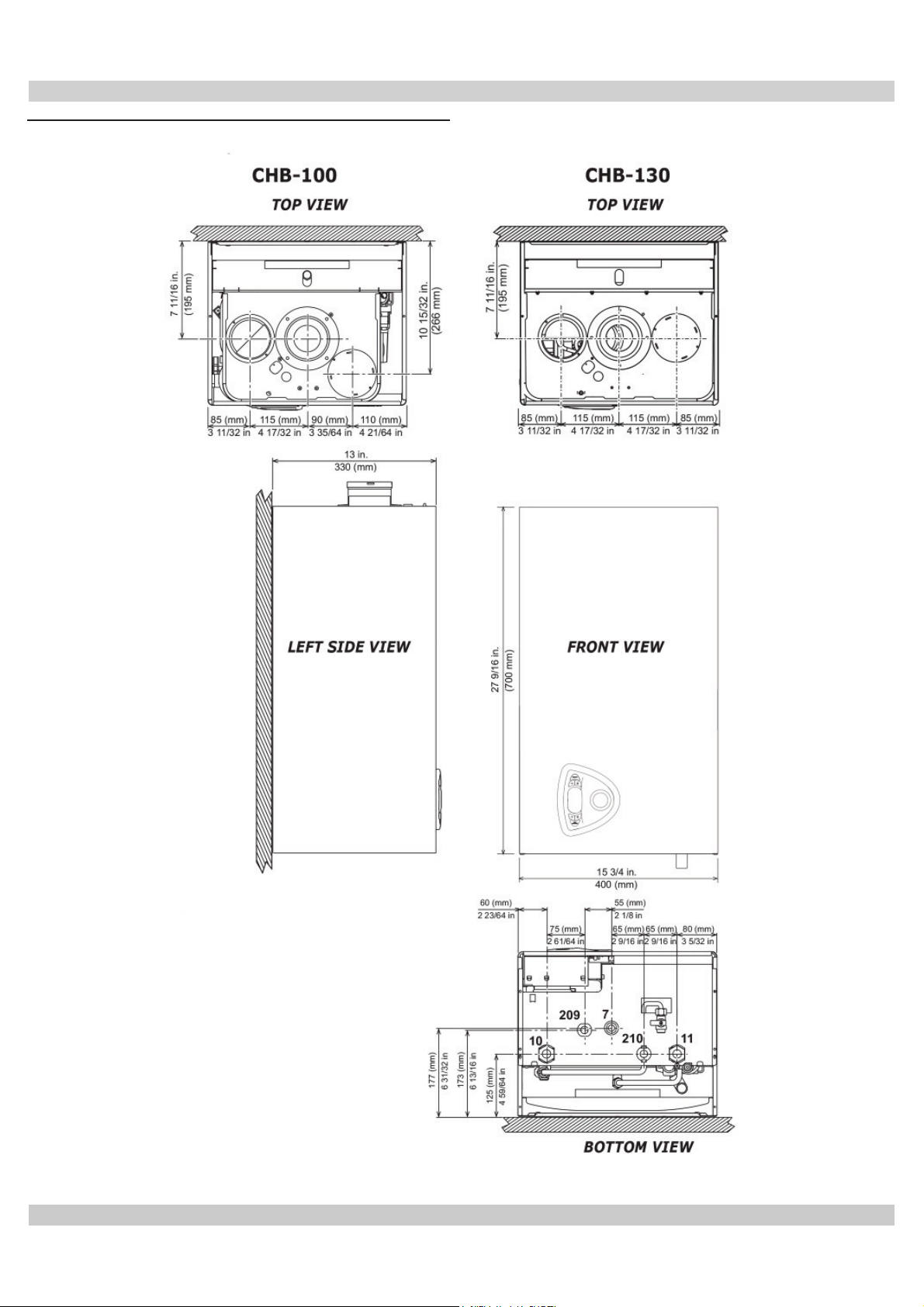
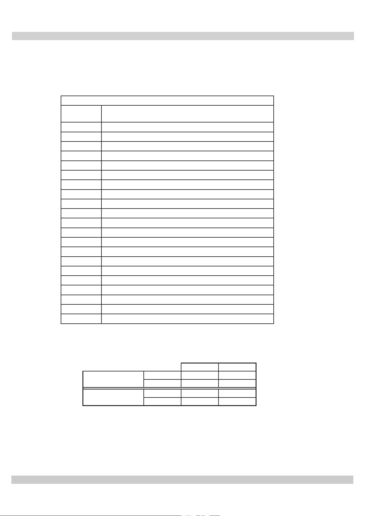
Figure 1 - Overall Dimensions
DIMENSIONS
7 = Gas Inlet - 3/4” FPT
10 = System Delivery - 1” MPT
11 = System Return - 1” MPT
*209 = Hot Water Tank Delivery - 3/4” Capped
*210 = Hot Water Tank Return - 3/4” Capped
* BSPT To NPT Adapters Included
2
Page 3

TABLE OF CONTENTS
1 - Introduction ................................................................................................................... 4
2 - Important Safety Information ........................................................................................... 5
3 - General view and main components .................................................................................. 6
4 - Locating Boiler ............................................................................................................... 9
5 - Hydronic Piping ............................................................................................................11
6 - Combustion Air And Vent Piping - Category I (Chimney Vent) ............................................ 15
6 - Combustion Air And Vent Piping of direct vent and Category III .......................................... 17
7 - Gas Supply Piping ......................................................................................................... 22
8 - Electrical Connections ................................................................................................... 23
9 - Start Up Procedure ....................................................................................................... 24
10 - Operating Instructions ................................................................................................. 26
11 - General Maintenance And Cleaning ................................................................................ 32
12 - Ratings And Capacities ................................................................................................ 33
13 - Trouble Shooting......................................................................................................... 36
Wiring diagram ............................................................................................................... 37
Repair Parts List - CHB-100 ............................................................................................. 38
Repair Parts List - CHB-130 ............................................................................................. 44
3
Page 4

1 - INTRODUCTION
1.1 Designated Use
• Hot water heating boiler.
• Indoor installation.
• Closet or alcove installation.
• Catagory I or III Venting.
• For use with natural gas or liquefi ed petroleum gases
(LP/propane). LP kit available.
• Indirect heating is acceptable.
• Boiler is arranged for connection to an external
storage tank for hot water production (optional).
All functions relevant to domestic hot water
production are only active with the optional water
tank sensor connected.
1.2 The unit MUST NOT:
•
Directly heat potable water.
• Heat water with non-hydronic heating system chemicals
present (example, swimming pool water).
• Exceed 185°F (85°C) system design temperature.
• Exceed 43.5 PSIG
1.3 Operational Features
• Modulating: 3-1 turn down.
• Integral Dual Limit.
Information and specifi cations outlined in this manual in effect at the
time of printing of this manual. ECR International, Inc. reserves the right to
discontinue, change specifi cations or system design at any time without
notice and without incurring any obligation, whatsoever.
4
Page 5
2 - IMPORTANT SAFETY INFORMATION
!
2.1 General
Boiler installation shall be completed by qualifi ed agency.
See glossary for additional information.
WARNING
!
2.3 Installation shall conform to requirements of
authority having jurisdiction or in absence of such
requirements:
•
Fire, explosion, asphyxiation and electrical
shock hazard. Improper installation could
• Canada
result in death or serious injury. Read this
manual and understand all requirements
before beginning installation.
2.2 Become familiar with symbols identifying
potential hazards.
This is the safety alert symbol. Symbol alerts you to
potential personal injury hazards. Obey all safety messages
following this symbol to avoid possible injury or death.
!
DANGER
Indicates a hazardous situation which, if not
2.4 Requirements for Commonwealth of
Massachusetts:
Boiler installation must conform to Commonwealth of
Massachusetts code 248 CMR which includes but is not
limited to:
• Installation by licensed plumber or gas fi tter.
2.5
Where required by the authority having jurisdiction, the
installation must conform to the
Standard for Controls and Safety Devices for Automatically
Fired Boilers, ANSI/ASME CSD1.
avoided, WILL result in death or serious injury.
United States
• National Fuel Gas Code, ANSI Z223.1/NFPA 54
• National Electrical Code, NFPA 70.
• Natural Gas and Propane Installation Code,
CAN/CSA B149.1.
• Canadian Electrical Code, Part I, Safety Standard
for Electrical Installations, CSA C22.1
.
!
WARNING
Indicates a hazardous situation which, if not
avoided, could result in death or serious injury.
!
CAUTION
Indicates a hazardous situation which, if not
avoided, could result in minor or moderate
injury.
NOTICE
Used to address practices not related to
personal injury.
5
Page 6
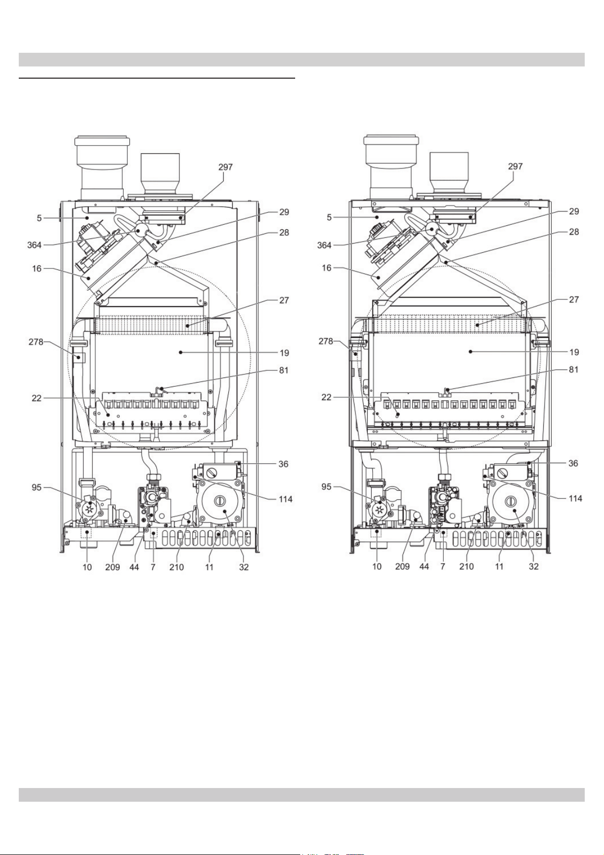
3 - GENERAL VIEW AND MAIN COMPONENTS
Figure 2 Component Listing
6
Page 7
3 - GENERAL VIEW AND MAIN COMPONENTS
Item
Number
5 Sealed Chamber
7 Gas Inlet
10 Supply System
11 System Return
16 Modulating Fan
19 Combustion Chamber
22 Burner
27 Copper Heat Exchanger
28 Exhaust Manifold
29 Exhaust Outlet Manifold
32 Heating circulating pump
36 Automatic Air Vent
44 Gas Valve
81 Ignition and Detection Electrode
95 3 Way Diverter Valve
114 Water Pressure Switch
209 Hot Water Tank Delivery
210 Hot Water Tank Return
278 Double Sensor - High Limit NTC
297 Air Pressure Switch
364 Condensation Coupling
Description
Unit Weight
Shipping Weight
LBS Kg
CHB 100 61 27.5
CHB 130 65 29.5
CHB 100 65 29.5
CHB 130 69 31.5
7
Page 8
3 - GENERAL VIEW AND MAIN COMPONENTS
WARNING
!
Fire, explosion, asphyxiation and electrical
shock hazard. Disconnect electrical power
supply and turn off gas at shutoff valve before
attemting to remove boiler jacket. Failure to
follow these instructions could result in death
or serious injury.
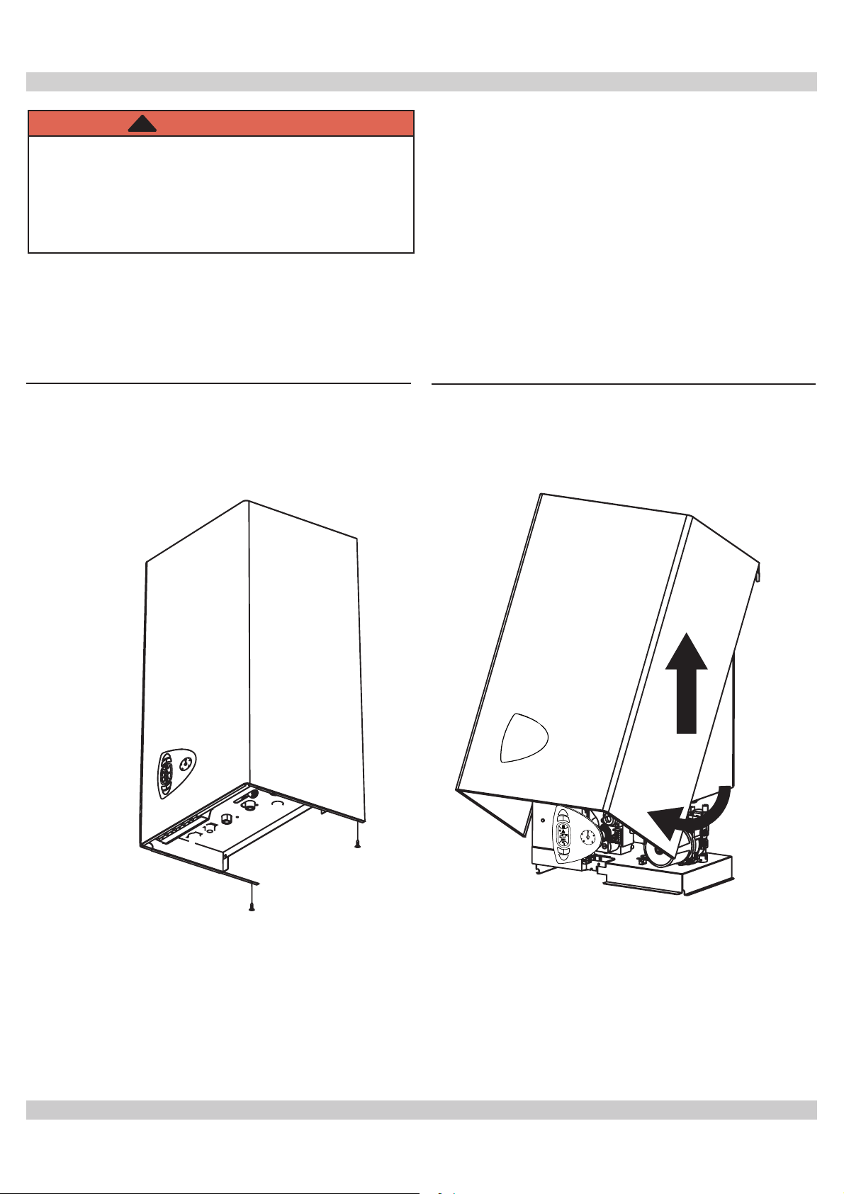
Remove Boiler Jacket
1.
Unscrew screws (A).
2.
Pivot jacket upwards. See fi gure 3.
3.
Raise Jacket up and off boiler. See fi gure 4.
Figure 3 - Jacket Removal - Screw
Locations
Figure 4 - Pivot Jacket and Raise to Remove
3
2
A
A
1
8
Page 9
4 - LOCATING BOILER
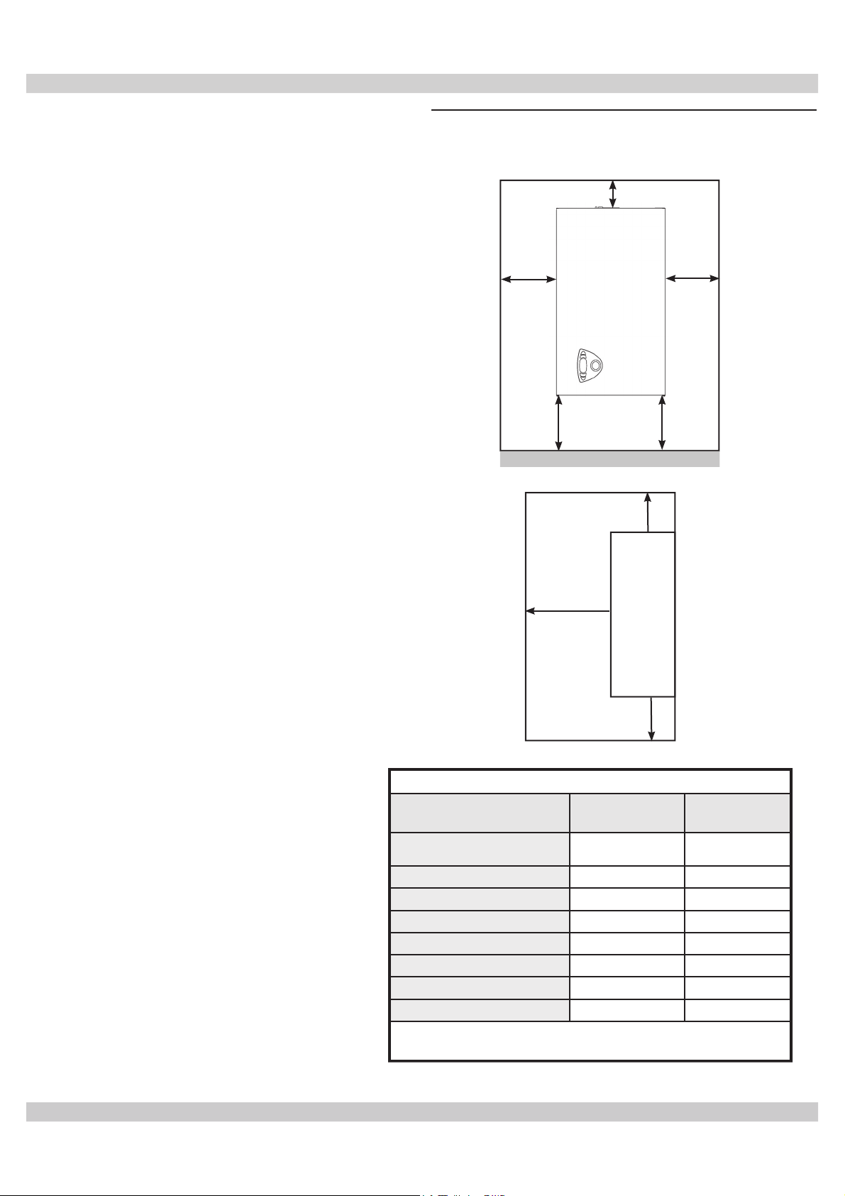
4.1 Boiler Location Considerations
• Ambient room temperature always above 32°F (0°C) to
Figure 5 - Boiler Clearances
prevent freezing.
• Approved for installation in closets.
• Protect gas ignition system components from water
(dripping, spraying, rain, etc.) during operation and
service (circulator replacement, control replacement,
etc.).
• Wall mount only.
• Access to outdoors to meet minimum and maximum
pipe lengths for combustion air and vent piping. See
section 6.
• Drainage of water (or water - antifreeze solution) during
boiler service or from safety relief valve discharge. See
section 5.
• Access to system water piping, gas supply, and electrical
service. See sections 5, 7 and 8.
• Clearances to combustible materials and service
clearances. See Table 1 and fi gure 5.
• The boiler must not be installed on carpeting.
A
BC
F
Boiler
(Front View)
F
FLOOR
A
Boiler
D
(Side View)
Front
F
TABLE 1: BOILER CLEARANCES
Dimension
Top (A)
Left Side (B))
Right Side (C)
Front (D)
Back (E)
Bottom (F)
Combustion Air/piping
Vent piping
(1)
Required distances measured from boiler jacket.
(2)
Service, proper operation clearance recommendation.
Combustible
Materials
(1)
16” (41cm) 16" (41cm)
0" (0 cm) 1” (3 cm)
0" (0 cm) 1” (3 cm)
0" (0 cm) 1" 3 cm)
0" (0 cm) 0” (0 cm)
0" (0 cm) 12" (30 cm)
0" (0 cm) 3/8" (1 cm)
6" (15 cm) 6" (15 cm)
Service
(1)(2)
9
Page 10
4 - LOCATING BOILER
!
4.2 Pre-pipe supply and return water connections
with factory fi ttings before wall mounting.
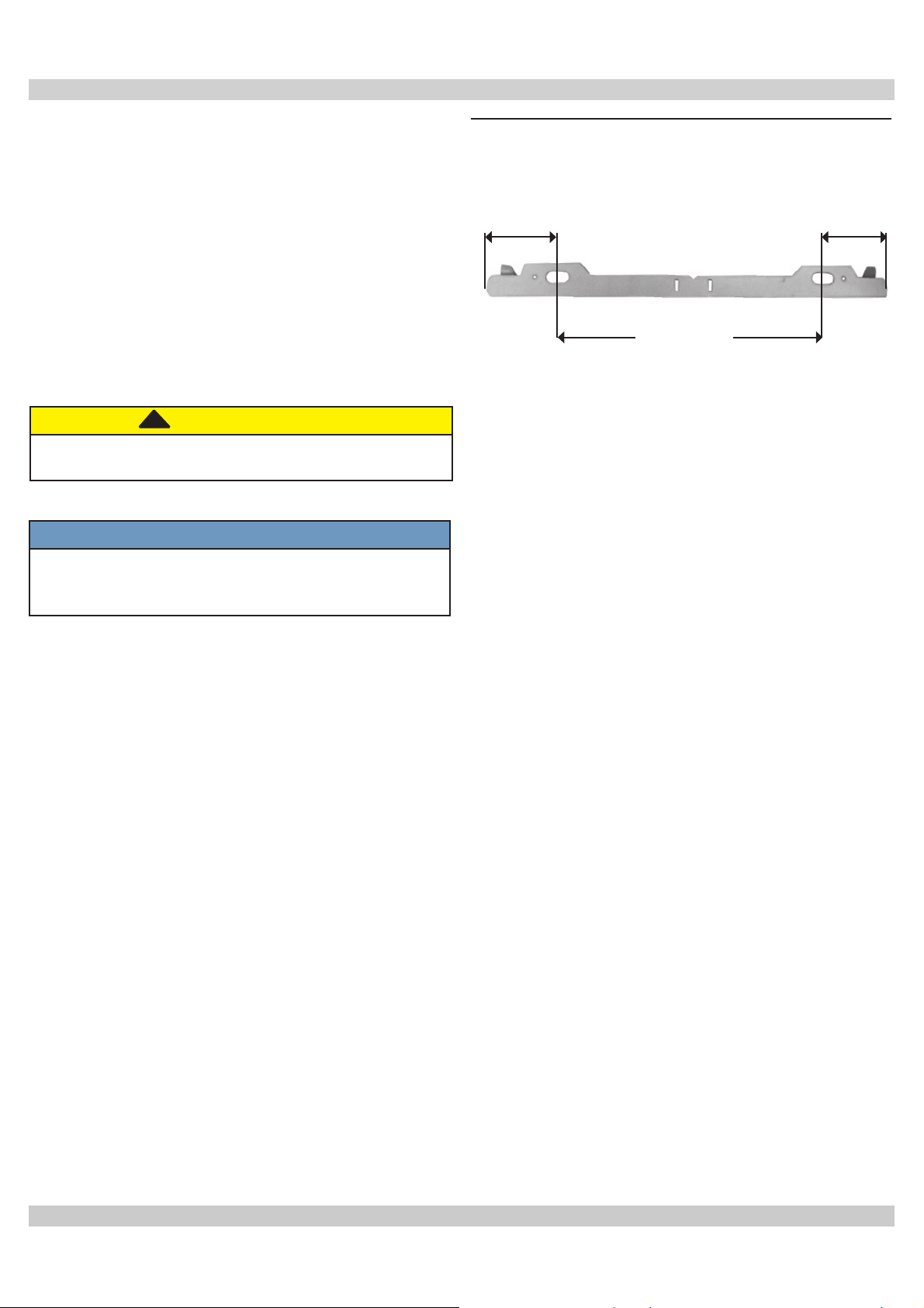
4.3 Wall Mounting
Mount boiler on wall using wall mounting bracket included
with unit.
• Structure must be capable of supporting boiler weight
plus 60 lbs (28 kg). See page 7.
• Wall mount bracket has 2 slots, spaced at
(23.5cm) on center
• Attach wall mount bracket level on wall.
• Boiler must engage with wall mount bracket. See fi gure 6.
Boiler weight exceeds 75 pounds (34 kg). Do not
lift boiler onto wall without assistance.
.
!
CAUTION
9¼”
NOTICE
Lift boiler using chassis. Using front jacket, vent
piping, water or gas fi ttings to lift boiler may cause
damage to the boiler.
Figure 6 - Wall Mounting Bracket
2⅜”
(2.4cm)
9¼” (23.5cm)
2⅜”
(2.4cm)
10
Page 11

5 - HYDRONIC PIPING
5.1 General
• Install piping in accordance with authority having jurisdiction.
NOTICE
Use two (2) wrenches when tightening and fi tting
pipe to boiler's threaded fi ttings. Boiler's internal
piping can be damaged if subjected to excessive
torque.
• Support system piping and safety relief valve discharge
piping. Boiler's internal piping and wall mount bracket
can be damaged if subjected to excessive weight.
• Size central heating pump (and domestic hot water
pump, if used) for system requirements only. Internal
heat exchanger pump compensates for pressure drop
through boiler internal piping and heat exchanger.
• Thoroughly clean and fl ush system before connecting to boiler.
• If oil is present in system water, use approved detergent to
wash system.
• Flush system to remove any solid objects such as metal chips,
fi bers, or Tefl on tape, etc.
Conditioning chemicals must ensure complete deoxygenation
of water and contain specifi c protective agents for yellow
metals (copper and its alloys), anti-fouling agents for
limescale at least up to 150 ppm CaCO3, pH neutral
stabilizers and, in low temperature systems, specifi c biocides
for use in heating systems.
In systems with continuous intake of oxygen (e.g. fl oor
systems without anti-diffusion pipes, open expansion
vessels), or intermittent (e.g. in case of frequent
replenishing), a separator must be provided. Regarding
domestic hot water (DHW), no type of treatment which
could prevent its possible food use can be provided for.
• Poison hazard. Ethylene glycol is toxic. Do not
• Never use automotive or standard glycol antifreeze,
• Ethylene glycol can attack gaskets and seals used
5.2 Water System Characteristics
• Water in the heating system must have protection of
metallic materials against corrosion.
• Filling water and subsequent replenishing, must be
clear, with hardness under 150 ppm CaCO3,
A. treated with approved conditioning chemicals
to ensure prevention of corrosion and attack on
metals and plastics, that gases do not form,
B. and bacterial or microbial masses do not proliferate
in low temperature systems.
• Hardness exceeding 150 ppm CaCO3, appropriate water
softening treatment and/or use of suitable anti-fouling
agents must be provided.
Water contained in the system must be checked at least
yearly and have:
A. pH above 7 and under 8.5 (under 8 with presence
of components in aluminum or light alloys),
B. iron content (Fe) less than 0.5 mg/l,
C. copper content (Cu) less than 0.1 mg/l,
D. total content of chlorides, nitrates and sulfates less
than 50mg/l,
E. must contain conditioning chemicals in
concentration suffi cient to protect system for a
year.
There must be no microbial or bacterial loads in low
temperature systems.
Conditioners, additives, inhibitors and anti-freeze fl uids can
be used only if manufacturer guarantees they are suitable
for use in heating systems and they do not cause damage
to heat exchanger or other components and/or materials of
boiler and system.
Use of generic chemicals not specifi cally suitable for use in
heating systems and/or incompatible with boiler materials
and system is forbidden.
• Use only inhibited propylene glycol solutions
• Thoroughly clean and fl ush any system that used
• Provide user with Material Safety Data Sheet
Do not expose boiler to freezing temperatures.
5.3 Special Conditions
• System piping exposed to freezing conditions: Use
• Boiler installed above radiation level (or as required by
• Boiler used in connection with refrigeration system.
WARNING
use ethylene glycol.
even ethylene glycol made for hydronic systems.
in hydronic systems.
certifi ed by fl uid manufacturer as acceptable for
use with closed water heating system.
glycol before installing new Boiler.
(MSDS) on fl uid used.
NOTICE
inhibited propylene glycol solutions certifi ed by fl uid
manufacturer for use with closed water heating system.
Do not use automotive or ethylene glycol.
authority having jurisdiction) shall have low water cutoff
protection.
Install piping in parallel with boiler, with appropriate
valves to prevent chilled medium from entering boiler.
11
Page 12
5 - HYDRONIC PIPING
• System piping connected to heating coils located in air
handling unit exposed to refrigerated air circulation. Install
fl ow control valves or other automatic means to prevent
gravity circulation of boiler water during cooling cycle
.
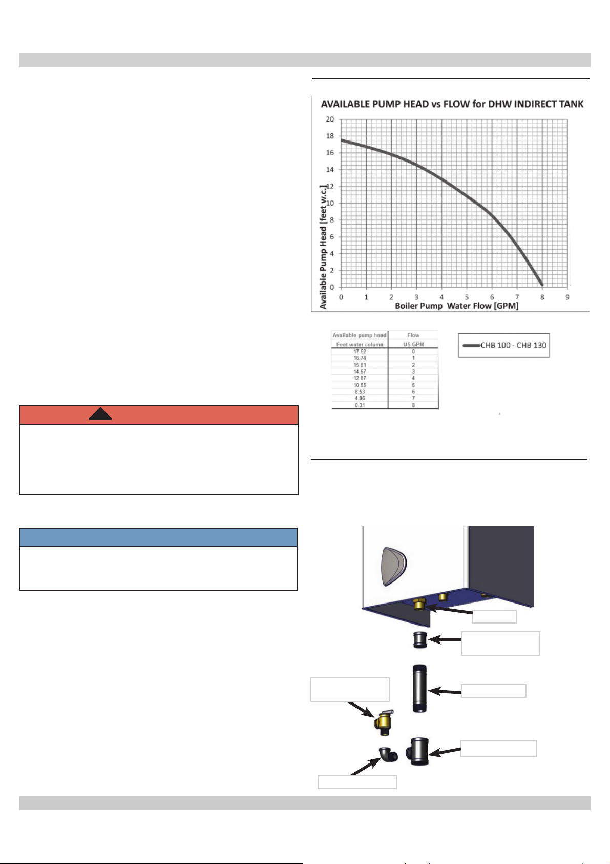
Figure 7 - Indirect Tank Performance Chart
5.4 Storage Tank Connection For Domestic Hot
Water Production
• Unit’s electronic board is arranged for managing an
external storage tank for domestic hot water production.
• See fi gure 10 for hydronic plumbing.
• Make electrical connections as shown on wiring diagram
page 36.
• Boiler’s control system recognizes presence of hot water
tank probe and automatically confi gures DHW function,
activating display and controls.
• Match Indirect tank heat exchanger and boiler capacity.
• Indirect tank requires dedicated pump. See fi gure 7 and
indirect tank specifi cation to determine pump.
• Incorrect tank size or insuffi cient fl ow may result in:
F. Unsatisfactory indirect tank performance.
G. Boiler short cycling
H. Extended DHW calls resulting in delayed response
to CH calls.
!
WARNING
Burn and Scald Hazard. Safety relief vlave
could discharge steam or hot water during
operation. Install discharge piping per these
instructions. Failure to do so could result in
death or serious injury.
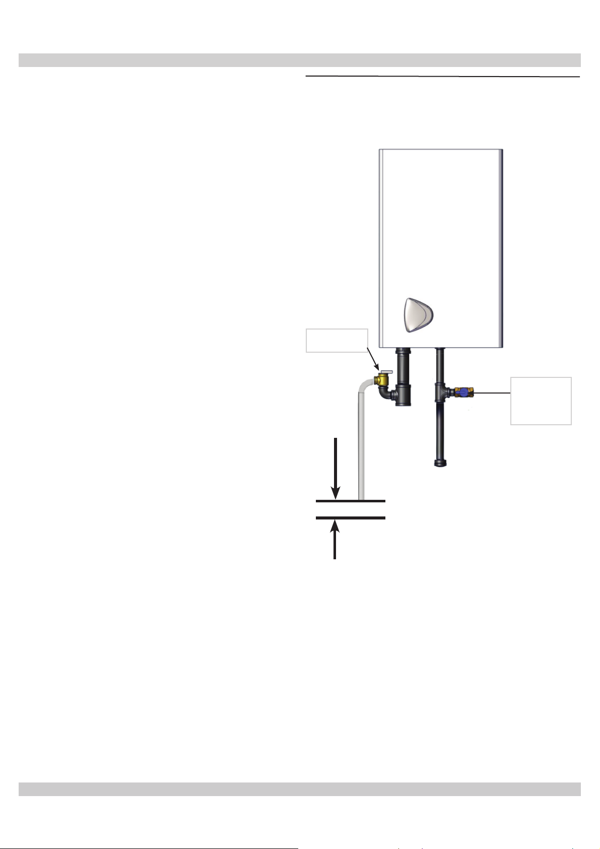
5.5 Safety Relief Valve
NOTICE
Boiler rated at 43.5 psig (.30MPa) maximum allowable
working pressure. Boiler provided with 30 psig
(.21MPa) safety relief valve.
• Install safety relief valve using pipe fi ttings provided with
boiler. See fi gure 8.
• Install safety relief valve with spindle in vertical position.
• Do not install shutoff valve between boiler and safety
relief valve.
• Install discharge piping from safety relief valve. See
fi gure 9.
• Use ¾” or larger pipe.
• Use pipe suitable for temperatures of 375°F (191°C)
or greater.
• Individual boiler discharge piping shall be independent
of other discharge piping.
Figure 8 - Safety Relief Valve & Air Vent
(Viewed from front of boiler)
1” MPT
Coupling 1” NPT
Safety Relief
Valve
Nipple 1” x 5”
Tee 1” x 1” x ¾”
Street Elbow ¾”
12
Page 13
5 - HYDRONIC PIPING
• Size and arrange discharge piping to avoid reducing
safety relief valve relieving capacity below minimum
relief valve capacity stated on rating plate.
• Run pipe as short and straight as possible to location
protecting user from scalding and properly drain
piping.
• Install union, if used, close to safety relief valve outlet.
• Install elbow(s), if used, close to safety relief valve
outlet and downstream of union (if used).
• Terminate pipe with plain end (not threaded).
Figure 9 - Safety Relief Valve Discharge
Safety Relief
Valve
Piping
Check Local Codes
for Maximum
Distance to Floor
Gas Shutoff
Valve
in Open
position
13
Page 14
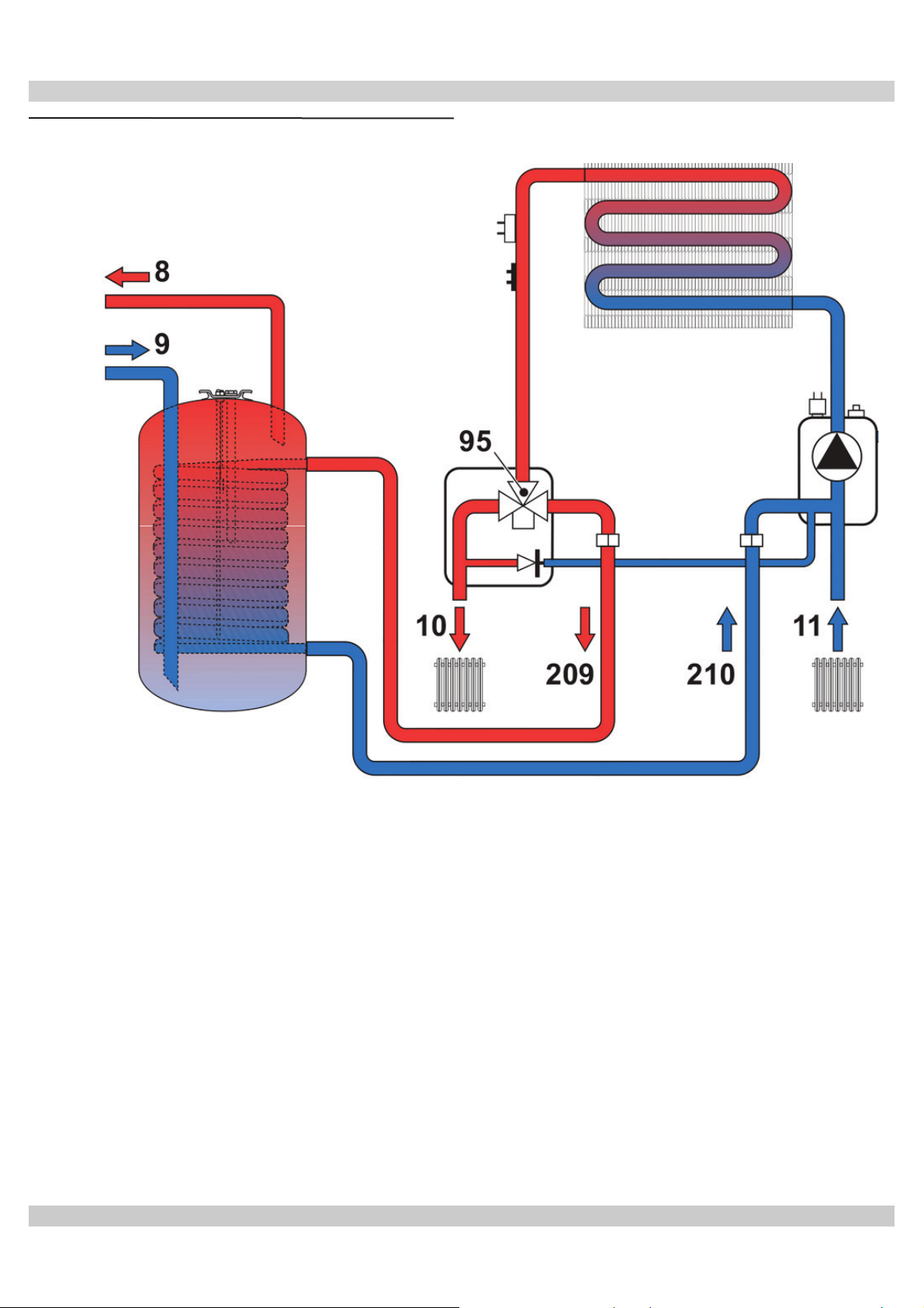
Figure 10 - Hydronic Piping
5 - HYDRONIC PIPING
8 Domestic Hot Water Outlet
9 Domestic Cold Water Inlet
10 Heating System Supply
11 Heating System Return
95 Diverter Valve
209 Hot Water Tank Delivery
210 Hot Water Tank Return
14
Page 15
6 - COMBUSTION AIR AND VENT PIPING - CATEGORY I (CHIMNEY VENT)
WARNING
!
Boiler and venting installations shall be performed
by a qualifi ed service agent and in accordance with
the appropriate manual. Installing or venting boiler
or other gas appliance with improper methods or
materials may result in serious injury or death due
to fi re or to asphyxiation from poisonous gases such
as carbon monoxide with is odorless and invisible.
!
WARNING
Do not connect boiler to any portion of mechanical
draft system operating under positive pressure.
6.1 Check Your Chimney
Chimney must be clean, right size, properly constructed
and in GOOD CONDITION.
1.
Installation must conform to requirements of the
authority having jurisdiction or, in absence of such
requirements, to the National Fuel Gas Code, ANSI
Z223.1/NFPA 54 and/or Natural Gas and Propane
Installation Code, CAN/CSA B149.1.
2.
Increaser fi tting is required on this boiler for Category I
venting, and 4” is minimum permissible vent diameter.
This does not imply vent connector is intended to be 4”
diameter pipe. Vent connector shall be sized according
to appropriate venting tables in the National Fuel
Gas Code and may be required to be larger than 4”
diameter.
7.
Common venting shall not be allowed. Boiler and
other certifi ed appliances. appliances can share same
chimney vent. Consult appropriate Vent Sizing Tables
in National Fuel Gas Code for specifi c requirements of
multiple appliance venting.
8.
Boiler is only appliance connected to vent, Type B vent
pipe is recommended for vent connector.
9.
Slope pipe up from boiler to chimney not less than 1/4”
per foot (21mm/m).
10.
End of vent pipe must be fl ush with inside face of
chimney fl ue. Use sealed-in thimble for chimney
connection.
11.
Fasten sections of vent pipe with sheet metal screws to
make piping rigid. Use stovepipe wires to support pipe
from above.
12.
Do not connect to fi replace fl ue.
13.
Do not install damper on this boiler.
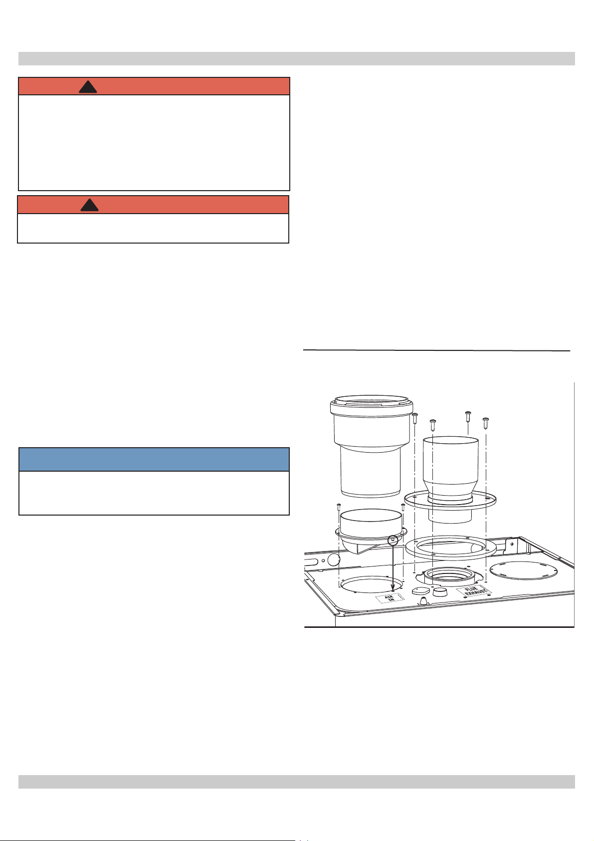
Figure 11 - Combustion Air Fitting
3
3
NOTICE
Boiler installation for chimney venting is not
complete unless increaser fi tting is located and
secured.
3.
These are Category I and Category III high effi ciency
boilers with lower stack or exhaust temperature.
4.
Venting into masonry chimney without liner, line
chimney from top to bottom with either:
A. Listed Type B vent pipe
B. Listed fl exible vent liner
C. Poured ceramic liner.
5.
Outside chimneys should not be used unless they are
(choose one of the following):
A. Enclosed in a chase
B. Lined with Type B vent pipe
C. Use listed fl exible vent liner
D. Use certifi ed chimney lining system
6.
Vent connector from boiler to chimney should run as
directly as possible with as few elbows as possible.
Horizontal Venting requires fi eld supplied appliance adapter
for the boiler fl ue outlet.
Boiler is provided with a 3” vent connection, 3” x 4”
increaser must be fi eld sourced for chimney application.
This does not mean that the connection to the chimney will
always be 4”.
15
Page 16

6 - COMBUSTION AIR AND VENT PIPING- CATEGORY I (CHIMNEY VENT)
6.2 Minimum Vent Pipe Clearance
• Use Type B vent pipe through crawl space. Where vent
pipe passes through combustible wall or partition, use
ventilated metal thimble. Thimble should be 4 inches
larger in diameter than vent pipe.
• Boiler installed with single wall vent, must have 6”
clearance between its surface and any combustible
material. New Type B gas vent or fl exible liner must be
installed in accordance with instructions furnished with
vent. Maintain clearances as specifi ed for vent pipe.
• Verify vent pipe is fi re-stopped where it goes through
fl oor or ceiling. It should have approved vent cap with
clearances from roof. If clearances are less than shown,
have vent checked by local authorities. Figure 13, Page
20.
• Vent connectors serving appliances vented by natural
draft shall not be connected into any portion of
mechanical draft systems operating under positive
pressure.
6.
7.
8.
6.3 Removing Existing Boiler From Common
Venting System
9.
When an existing boiler is removed from a common
venting system, common venting system is likely to be
too large for proper venting of the appliances remaining
connected to it.
1.
At the time of removal of an existing boiler, the
following steps shall be followed with each appliance
remaining connected to the common venting system
placed in operation, while the other appliance
remaining connected to the common venting system
are not in operation.
2.
Seal any unused openings in the common venting
system.
3.
Visually inspect the venting system for proper size and
horizontal pitch and determine there is no blockage or
restriction, leakage, corrosion and other defi ciencies
which could cause an unsafe condition.
4.
Insofar as is practical, close all building doors and
windows and all doors between the space in which the
appliances remaining connected to the common venting
system are located and other spaces of the building.
Turn on clothes dryers and any appliance not connected
to the common venting system. Turn on any exhaust
fans, such as range hoods and bathroom exhausts, so
they will operate at maximum speed. Do not operate a
summer exhaust fan. Close fi replace dampers.
5.
Place in operation the appliance being inspected. Follow
the lighting instructions. Adjust thermostat so appliance
will operate continuously.
6.4 Modulating Fan
6.5 Venting Materials
Test for spillage at the draft hood relief opening after
5 minutes of main burner operation. Use fl ame of a
match or candle, or smoke from a cigarette, cigar, or
pipe.
After it has been determined that each appliance
remaining connected to the common venting system
properly vents when tested as outlined above, return
doors, windows, exhaust fans, fi replace dampers and
any other gas-burning appliance to their previous
conditions of use.
Any improper operation of the common venting system
should be corrected so the installation conforms with
the National Fuel gas Code, ANSI Z223.1/NFPA 54,
and/or the Natural Gas and Propane Installation Code,
CAN/CSA B149.1. When re-sizing any portion of the
common venting system, the common venting system
should be re-sized to approach the minimum size
determined using the appropriate tables in Chapter 13
of the National Fuel Gas Code, ANSI Z223.1/NFPA 54,
and/or the Natural Gas and Propane Installation Code,
CAN/CSA B149.1.
It is recommended that existing gas vents be checked
to be sure they meet local codes.
• Unit is equipped with an advanced combustion air, vent
fl ow control system, with modulating fan and pressure
sensor.
• Unit automatically adapts its operation to fl ue type
and length, without requiring adjustments during
installation or use of baffl es in combustion circuit.
• Unit consistantly and automatically regulates
combustion air and vent fl ow according to change in
thermal load. Combustion and heat exchange occur in
optimum conditions. Unit’s thermal effi ciency remains
high throughout its power range.
• See Table 3
Table 3 - Combustion Air and Vent Pipe Fittings
Category I (Chimney Vent)
Item Material Standards
Type B Vent UL 441, ULC S605
Vent Pipe & Fittings
Combustion Air
Masonry Chimney
- must conform to
proper sizing and
materials
Stainelss Steel,
PVC, CPVC, PP,
Aluminum
National Fuel
Gas Code, ANSI
Z223.1/NFPA 54
ANSI/ASTM
D2564, ANSI/
ASTM F493, UL
1738/ULC636-08
16
Page 17

6 - COMBUSTION AIR AND VENT PIPING OF DIRECT VENT AND CATEGORY III
Induced Draft Boilers
Horizontal (Category III) venting systems installation
shall conform to the requirements of the authority having
jurisdiction or, in the absence of such requirements, to
the National Fuel Gas Code, ANSI Z223.1/NFPA 54, and/
or Natural Gas and Propane Installation Code, CAN/CSA
B149.1
1.
Boilers may be vented horizontally. Vent pipe is pitched
down from boiler to vent termination. Do not connect
other appliances to this vent.
2.
Vent Pipe Material UL Listed - AL294C Stainless Steel
vent pipe and fi ttings.
3.
Clearance to Combustible Materials: For stainless steel
vent pipe maintain 6” minimum air space clearance to
combustible materials.
4.
Vent Pipe Size: 3” vent pipe connected directly to the
outlet of the induced draft blower.
5.
Vent Pipe Length:
A. For stainless steel vent pipe, the maximum
horizontal vent length is 65 equivalent feet.
B. Minimum horizontal vent length is 5 equivalent
feet.
C. For 3” 90° elbows = 5 equivalent feet of vent
length.
6.
Vent Termination Fitting: For all vent pipe materials,
you may use either:
A. 90° elbow pointing down, fi tted with a minimum
1/4” mesh screen to keep out rodents and birds.
The elbow shall be of the same material and size
as vent pipe. The elbow exit should be at least 6”
away from exterior wall.
-orB. Concentric side wall vent hood.
7.
Vent Pipe Termination Location :
A. When venting through combustible walls,
combustible clearances must be considered. ECR
vent termination, 5612601, is a certifi ed direct vent
termination (for Catagory III venting) providing
both the outside vent termination and a double
wall pipe for passing through a combustible
wall up to 10” thick. Vent terminations by other
manufacturers may also be used as long as they
are certifi ed for catagory III venting.
B. If the 90° elbow is the termination fi tting of choice,
then the single wall pipe will be passing through the
side wall. For combustible walls, a UL listed thimble
shall be used where the single wall pipe passes
through the wall.
C. For single wall pipe through non-combustible
walls, the hole through the wall need only be large
enough to maintain the pitch of the vent pipe, and
provide proper sealing. A thimble is not required for
single wall pipe passing through non-combustible
walls.
8.
9.
17
D. The venting system shall terminate at least 3 feet
0.9m) above any forced air inlet located within
10 feet (3m). The venting system shall terminate
at least 4 feet (1.2m) below, 4 feet (1.2m)
horizontally from, or 1 foot (300 mm) above any
door, window, or gravity air inlet into any building.
The bottom of the vent shall be located at least 12
inches (300mm) above grade. Termination of the
vent shall be not less than 7 feet (2.13m) above
adjacent public walkway. The vent terminal shall
not be installed closer than 3 feet (0.9m) from the
inside corner of an L shaped structure. Termination
of the vent should be kept at least 3 feet (0.9m)
away from vegetation. The venting system shall
terminate at least 4 feet horizontally from, and in
no case above or below, unless a 4 foot horizontal
distance is maintained, from electric meters, gas
meters, regulators, and relief equipment.
• The venting system shall terminate at least 4 feet
below any eave, soffi t, or roof overhang.
• The venting system shall not terminate
underneath any deck, patio, or similar structure.
• Put vent on a wall away from the prevailing
winter wind. Locate or guard the vent to prevent
accidental contact with people or pets.
• Terminate the vent above normal snow-line. Avoid
locations where snow may drift and block the
vent. Ice or snow may cause the boiler to shut
down if the vent becomes obstructed.
• Under certain conditions, fl ue gas will condense,
forming moisture. In such cases, steps should be
taken to prevent building materials at the vent
terminal from being damaged by exhaust of fl ue
gas.
United States - Terminate vent system at least
4 feet (1.22m) horizontally from, and in no case
above or below, unless a 4 feet (1.22m) horizontal
distance is maintained, from electric meters, gas
meters, regulators and relief equipment.
Canada - Terminate vent system at least 6 feet
(1.83 m) horizontally from, and in no case above
or below, unless a 6 feet (1.83m) horizontal
distance is maintained, from electric meters, gas
meters, regulators and relief equipment.
Joining and Sealing the Vent Pipe: The vent pipe needs
to be both watertight and gas tight. Seal all joints and
seams following vent pipe manufacture’s installation
instructions.
Support Spacing: Do not restrict thermal expansion
movement of the vent. The vent pipe must expand
and contract freely with temperature change. Each run
of vent piping shall be supported following vent pipe
manufacture’s instructions.
Page 18

6 - COMBUSTION AIR AND VENT PIPING OF DIRECT VENT AND CATEGORY III
10.
If the horizontal vent must go through a crawl space or
other unheated space, the cool temperatures will likely
cause the fl ue gases to continuously condense inside
the vent pipe. Do not insulate the vent pipe. It must be
visible for monthly inspection. Insure that the vent pipe
is properly pitched away from the boiler, with no low
spots, so that condensate in the vent will drain away
from the boiler. An insulated enclosure or chase, with
access for inspection and servicing of the vent, may
be required to prevent freezing of liquid condensate.
Consult the vent pipe manufacturer’s instructions for
specifi c guidelines.
11.
At beginning of each heating season and monthly
during the heating season, check all vent pipes and
vent terminal to make sure there are no obstructions.
Periodically clean the screen in the vent terminal.
Table 4 - Combustion Air and Vent Pipe Fittings
!
WARNING
Vent extending through exterior wall shall not
terminate adjacent to wall or below building
extensions such as eaves, balconies, parapets or
decks. Failure to comply could result in death or
serious injury.
Type Item Diameter Min Lenght Max Lenght Material Standards
Vent 3” 5 ft 65 ft
Direct vent
Air intake 3” 5 ft 65 ft
Category III Vent 3” 5 ft 65 ft
AL294C Stainless
Steel, Aluminum
Stainelss Steel,
PVC, CPVC, PP,
Aluminum
AL294C Stainless
Steel, Aluminum
UL1738,
ULC S636
ANSI/ASTM
D2564, ANSI/
ASTM F493, UL
1738/ULC636-08
UL1738,
ULC S636
Equivalent Length of Venting Components:
5 ft. equivalent for a 3” 90° elbow.
2 1/2 ft. equivalent for a 3” 45° elbow.
18
Page 19

6 - COMBUSTION AIR AND VENTILATION
Provide combustion air and ventilation air in accordance
with the section “Air for Combustion and Ventilation,”
of the National Fuel Gas Code, ANSI Z223.1/NFPA 54,
or Sections 8.2, 8.3 or 8.4 of Natural Gas and Propane
Installation Code, CAN/CSA B149.1, or applicable
provisions of local building codes.
Provide make-up air where exhaust fans, clothes dryers,
and kitchen ventilation equipment interfere with proper
operation.
National Fuel Gas Code recognizes several methods
of obtaining adequate ventilation and combustion air.
Requirements of the authority having jurisdiction may
override these methods.
• Engineered Installations. Must be approved by
authority having jurisdictions.
• Mechanical Air Supply. Provide minimum of 0.35
cfm per Mbh for all appliances located within space.
Additional requirements where exhaust fans installed.
Interlock each appliance to mechanical air supply
system to prevent main burner operation when
mechanical air supply system not operating.
• All Indoor Air. Calculate minimum volume for all
appliances in space. Use a different method if
minimum volume not available.
◊ Standard Method. Cannot be used if known air
infi ltration rate is less than 0.40 air changes per
hour. See Table 5 for space with boiler only. Use
equation for multiple appliances.
Volume ≥ 50 ft3 x Total Input [Mbh]
◊ Known Air Infi ltration Rate. See Table 3 for
space with boiler only. Use equation for multiple
appliances. Do not use an air infi ltration rate (ACH)
greater than 0.60.
Volume ≥ 15 ft3/ACH x Total Input [Mbh]
◊ Refer to National Fuel Gas Code for opening
requirements between connection indoor spaces.
• All Outdoor Air. Provide permanent opening(s)
communicating directly or by ducts with outdoors.
◊ Two Permanent Opening Method. Provide opening
commencing within 12 inches of top and second
opening commencing within 12 inches of bottom
enclosure.
Direct communication with outdoors or
communicating through vertical ducts. Provide
minimum free area of 1 in2 per 4 Mbh of total input
rating of all appliances in enclosure.
Communicating through horizontal ducts. Provide
minimum free area of 1 in2 per 2 Mbh of total input
rating of all appliances in enclosure.
◊ One Permanent Opening Method. Provide opening
commencing within 12 inches of top of enclosure.
Provide minimum clearance of 1 inch on sides
and back and 6 inches on front of boiler (does not
supersede clearance to combustible materials).
◊ Combination Indoor and Outdoor Air. Refer to
National Fuel Gas Code for additional requirements
for louvers, grilles, screens and air ducts.
• Combination Indoor and Outdoor Air. Refer toNational
Fuel Gas Code for application information. National Gas
and Propane Installation Code Requires providing air
supply in accordance with:
• Section 8.2 and 8.3 when combination of appliances
has a total input of up to and including 400 Mbh
(120kW).
Does not have draft control device.
• Section 8.4 when combination of appliances has total
input exceeding 400 Mbh (120 kW).
• Refer to Natural Gas and Propane Installation Code
for specifi c air supply requirements for enclosure or
structure where boiler is installed, including air supply
openings and ducts.
Table 5 - Air Infi ltration
Input Mbh
100 5000 15,000 7,500 5,000 3,750 3,000 2,500
130 6500 19,500 9,750 6,500 4,875 3,900 3,250
Standard
Method
Known Air Infi ltration Rate Method (Air Changes Per Hour)
0.1 0.2 0.3 0.4 .05 0.6
19
Page 20

6 - COMBUSTION AIR AND VENT PIPING
Figure 12 - Horizontal Venting Clearances
Figure 13 - Two Pipe Venting
( = Combustion Air / = Venting)
NOTICE
Maintain 12” (30cm) US, 18” (46cm) Canada
clearance above highest anticipated snow level
or grade.
20
Page 21

6 - COMBUSTION AIR AND VENT PIPING
Figure 14 - Chimney Venting with Room Air
Single Wall
( = Combustion Air / = Venting)
NOTICE
Refer to section 6.1, numbers 3 through 12,
page 15 of this manual for proper installation.
Figure 15 - Chimney Venting with Outside Air
Single Wall
( = Combustion Air / = Venting)
DIRECT VENT BOILER - Boiler constructed and installed
so all combustion air is derived directly from outdoors and
all vent gases are discharged to outdoors. See Figure 15.
21
Page 22

7 - GAS SUPPLY PIPING
!
!
CAUTION
WHAT TO DO IF YOU SMELL GAS
• Do not try to light any appliance.
• Do not touch any electrical switch; do not use
any phone in your building.
• Immediately call your gas supplier from a
neighbor’s phone. Follow gas supplier’s
instructions.
• If you cannot reach your gas supplier, call the fi re
department.
7.1 General
• Use piping materials and joining methods acceptable
to authority having jurisdiction. In absence of such
requirements:
• USA - National Fuel Gas Code, ANSI Z223.1/NFPA
54
• Canada - Natural Gas and Propane Installation Code,
CAN/CSA B149.1
• Size and install gas piping system to provide suffi cient
gas supply to meet maximum input at not less than
minimum supply pressure. See Table 6.
• Support piping with hooks straps, bands, brackets,
hangers, or building structure components to prevent or
dampen excessive vibrations and prevent strain on gas
connection. Boiler will not support piping weight.
• Use thread (joint) compound (pipe dope) suitable for
liquefi ed petroleum gas.
• Provide sediment trap up stream of gas valve.
• Install manual main shutoff valve outside of jacket. See
fi gure 16.
Figure 16 Manual Main Gas Shutoff Valve
Outside Boiler Jacket
With Manufacturer Suggested Piping With Drip Leg
Gas
Connection
Nipple
¾” x 3” NPT
Tee ¾” NPT
¾” Gas
Shutoff
Valve in ON
Postion
Nipple ¾ x
3” NPT
¾” Pipe Cap
Nipple
¾ x 3”
NPT
7.2 Conversion To LP
Refer to Gas Conversion Kit Instructions.
!
DANGER
Fire Hazard. Do not use matches, candles, open
fl ames, or other methods providing ignition source.
Failure to comply will result in death or serious
injury.
7.3
Leak Check Gas Piping
Pressure test boiler and gas connection before placing
boiler in operation.
• Pressure test over 1/2 psig (3.5 kPa). Disconnect
boiler and its individual gas shutoff valve from gas
supply system.
• Pressure test at 1/2 psig (3.5 kPa) or less. Isolate
boiler from gas supply system by closing manual gas
shutoff valve. See fi gure 16.
• Locate leakage using gas detector, noncorrosive
detection fl uid, or other leak detection method
acceptable to authority having jurisdiction. Do not use
matches, candles, open fl ames, or other methods that
can provide ignition source.
• Correct leaks immediately and retest.
Manufacturer suggested gas piping with drip leg.
Table 6 - Gas Supply Pressure
Gas Supply Pressure
Natural Gas
Min. Max.
3.5" w.c.
(0.7 kPa)
14" w.c. (3.3
kPa)
22
Page 23

8 - ELECTRICAL CONNECTIONS
!
WARNING
Electrical shock hazard. Turn OFF electrical power
supply at service panel before making electrical
connections. Failure to do so could result in death
or serious injury.
8.1 General
Electrically bond boiler to ground in accordance with
requirements of authority having jurisdiction. Refer to:
• USA- National Electrical Code, ANSI/NFPA 70.
• Canada - Canadian Electrical Code, Part I, CSA C22.1:
Safety Standard for Electrical Installations.
8.2 Line Voltage Connections - Boiler
Provide individual 120V, 15 amp circuit (recommended)
with fused disconnect or service switch as required by
authority having jurisdiction.
8.3 Central Heating Thermostat
A. Use thermostat or boiler system control with
dry contacts rated 0.5 amps @ 120 VAC. Boiler
control does not provide 24 VAC power to central
heating thermostat. Do not use to power 24VAC
thermostat.
B. Locate and install thermostat per manufacturer's
instructions. Maximum wire length is 330 ft (100m)
for 22 ga. wire.
C. Connect wires to terminals 1 and 2 as shown in
fi gure 17. Wires are interchangeable.
Figure 17 - Terminal Block
2
1 - Thermostat or dry contacts
2 - 138 = Optional External Outdoor Reset Sensor
Connections on 5 & 6 terminals
155 = Optional Indirect Tank Sensor
Connections on 7 & 8 terminals
370 = Low Water Cutoff (LWCO) - fi eld source
Connections on 1 & 2 terminals are 120 Volts A/C.
Connections on 3 & 4 are dry contact only.
23
Page 24

9 - START UP PROCEDURE
9.1 Fill Boiler With Water And Purge Air
NOTICE
To maintain boiler effi ciency and prevent boiling
inside the heat exchanger, fl ush entire heating
system until clean.
• Flush heating system, including all heating zones.
• Fill boiler with potable water.
• Fill boiler and system piping with water (or
antifreeze-water solution, if used). See antifreeze
information Section 5.3 page 11. Purge air from
boiler using air vent. Purge air from system piping.
• Inspect system piping and boiler connections.
Repair any leaks immediately.
• Activate all heating zones and calls for heat,
including CH calls and DHW calls (if available).
• Do not open gas shutoff valve until all air is purged
from system.
9.2 Boiler Start-up and Operational Test
1.
Verify air is purged from hydronic piping
2.
System test pumps - verify each pump is
operational
3.
Verify gas piping
• Confi rm pressure test. See section 7.3 page 22.
• Visually inspect piping to determine there are no
open fi ttings or ends, and all valves at unused
outlets are closed and plugged/capped.
• Purge air from piping
• Check piping and connections for leaks immediately
after gas is turned on. Shut off gas supply and
make necessary repairs if leaks found.
4.
Follow OPERATING INSTRUCTIONS to initiate boiler
operation. See section 10.
5.
Inspect combustion air and vent piping. Verify pipe
is not leaking and terminations are unobstructed and
vent gas discharge is not a nuisance or hazard.
6.
Verify boiler operates.
7.
Check control module operation.
8.
Check fi eld sourced limits, low water cutoffs, etc. per
manufacturer's instructions.
WARNING
!
Asphyxiation hazard. Carbon monoxide is odorless,
tasteless, clear colorless gas, which is highly toxic.
Carbon monoxide production shall not exceed
400ppm. Failure to follow these instructions could
result in death or serious injury.
WARNING
!
Asphyxiation hazard. Verify cap is fi rmly placed on
combustion analyzer port to prevent CO emission.
Failure to do so could result in death or serious
injury.
9.3 Burner Pressure Adjustment
Unit has fl ame modulation, with two fi xed pressure values:
minimum and maximum. See sec. 12, page 33.
Connect pressure gauge to pressure point “B” downstream
of the gas valve.
1.
Remove protection cap “D”.
2.
Operate boiler in TEST mode.
3.
Adjust maximum pressure by turning screw “G”
clockwise ↷ to increase pressure and counter clockwise
↶ to decrease.
4.
Disconnect one of two connectors “C” from modulation
regulator “F” on the gas valve.
5.
Adjust minimum pressure by turning screw “E” clockwise
↷
to increase the pressure and counter clockwise ↶ to
decrease it.
6.
Turn burner on and off, verify minimum pressure
remains stable.
7.
Reconnect connector “C” detached from modulation
regulator “F” on the gas valve.
8.
Verify maximum pressure has not changed.
9.
Replace protection cap “D”.
10.
To end TEST mode, repeat activation sequence or wait
15 minutes.
9.4 To Enter Test Mode/Adjust Heating Power
Press CH+/- buttons at the same time for 5 seconds.
• 3 way valve is in CH position and burner is forced at
100%. Boiler automatically exits test mode after 15
minutes or to exit test mode manually press CH +/buttons together for 5 seconds.
• With Ch +/- buttons you can adjust Max power from (0
to 100%)
9.5 Ignition Adjustment
To adjust ignition, switch boiler to TEST mode (See Start
up Procedure). Press DHW buttons to increase or decrease
power (min.= 00, max. = 60). Press RESET button within
5 seconds and ignition remains set. Exit TEST mode.
24
Page 25

9 - START UP PROCEDURE
9.6 Check Combustion
Natural Gas
1. Measure input. English unitsTurn off gas to all other
appliances.
•
Activate some heating zones to dissipate heat.
•
Set boiler on high fi re.
•
Use ½, 1 or 2 cu ft dial on gas meter. Measure
time required for one or more complete
revolutions. Measure time for 1-2 minutes.
•
Calculate input.
Input (MBH) =
Example: Gas fl ow from
Meter = 2 cu ft
Measured time = 72 seconds
Rate (MBH) =
3600 x cu ft
seconds
3600 x 2 cu ft
= 100 MBH
72 seconds
Figure 18 - Test Ports
Vent Gases Test
Port
Combustion Air Test
Port
Table 7 - Combustion Table
Figure 19 - Gas Valve
Two sampling points are available at top of the boiler, one
for venting and the other for combustion air. To sample:
Open the air/vent outlet plug.
Insert probes all the way in.
Turn on TEST mode, wait 10 minutes for boiler to stabilize;
Take measurement.
E
G
A Pressure point upstream
B Pressure point downstream
C Modureg electrical connection
D Protection cap
E Minimum pressure adjustment
F Modureg
G Maximum pressure adjustment
I Gas valve electrical connection
N Compensation tube
Combustion Minimum/Maximum
Natural Gas
High Fire - CO2 at 100 (%) 7.3 - 7.8
Low Fire - CO2 at 33 (%) 3.0 - 5.0
N
N
C
D
F
C
D
B
I
A
25
Page 26

!
10 - OPERATING INSTRUCTIONS
!
WARNING
If you do not follow these instructions
exactly, a fi re or explosion may result
causing property damage, personal injury
or loss of life.
• This appliance is equipped with an ignition device
which automatically lights burner. Do NOT try to
light this burner by hand.
• Before operating smell all around appliance area
for gas. Be sure to smell next to fl oor because
some gas is heavier than air and will settle to the
fl oor.
• Use only your hand to turn the gas shutoff
valve. Never use tools. If valve will not turn
by hand, do not try to repair it, call a qualifi ed
service technician. Force or attempted repair may
result in fi re or explosion.
• Do not use this appliance if any part has
been under water. Immediately call a qualifi ed
service technician to inspect appliance and to
replace any part of control system and any gas
control which has been under water.
!
CAUTION
WHAT TO DO IF YOU SMELL GAS
• Do not try to light any appliance.
• Do not touch any electrical switch; do not use
any phone in your building.
• Immediately call your gas supplier from a
neighbor’s phone. Follow the gas supplier’s
instructions.
• If you cannot reach your gas supplier, call the fi re
department.
10.2 TO TURN OFF GAS TO APPLIANCE
• Set thermostat to lowest setting.
• Turn "OFF" all electric power to appliance if service is
to be performed.
• Turn gas shutoff valve handle
Handle should be perpendicular to gas pipe.
Figure 20 Gas Shutoff Valve - Open Position
to closed position.
10.1 OPERATING INSTRUCTIONS
Stop! Read Safety information above.
• Set thermostat to lowest setting.
• Turn "OFF" all electrical power to appliance.
• This appliance is equipped with an ignition device which
automatically lights the burner. Do not try to light
burner by hand!
• Turn gas shutoff valve to closed position. Handle
should be perpendicular to gas pipe.
• Wait 5 minutes for any gas to clear. Smell for gas,
including near fl oor. If you smell gas, STOP! Follow
instructions on this page: “What To Do If You Smell
Gas.” If you do not smell gas, go to next step.
• Turn gas shutoff valve to open position. Handle
should be parallel to gas pipe.
• Turn "ON" electrical power to appliance.
• Set thermostat to desired setting.
• If the appliance will not operate, follow instructions TO
TURN OFF GAS TO APPLIANCE and call your service
technician or gas supplier.
OPEN
Figure 21 Gas Shutoff Valve - Closed Position
26
CLOSED
Page 27

10 - OPERATING INSTRUCTIONS
10.3 Checks During Operation
• Boiler is arranged for connection to an external storage
tank for hot water production (optional). All functions
relevant to domestic hot water production are only
active with the optional water tank connected.
• Check for leaks in piping systems. Correct immediately
if found.
• Check the effi ciency of the fl ue gases and combustion
air ducts while the boiler is working.
• Check water is circulating between boiler and systems.
• Verify the gas valve modulates correctly in both
heating and hot water production phases.
• Check proper ignition of the boiler by turning it on and
off with the room thermostat.
• Check parameters are programmed correctly and
perform any required customization (compensation
curve, power, temperatures, etc.)
10.4 Control Panel
14
43
6
10.5 Indicator During Operation
Heating
Call for heat (generated by Room Thermostat) is indicated
by hot air fl ashing above radiator symbol on the control.
Hot water
If optional tank sensor is installed call for hot water is
indicated by hot water fl ashing under the tap on the control.
64
13
15
10
11
12
5
8
9
217
Key
1 = DHW Temperature Setting Decrease Button
2 = DHW Temperature Setting Increase Button
3 = Heating System Temperature Setting Decrease Button - CH
4 = Heating System Temperature Setting Increase Button - CH
5 = Display
6 = Summer/Winter Mode Selection - Reset Button
Unit On/Off - Economy/Comfort Mode Selection Button
7 =
8 = DHW Symbol
9 = DHW Mode
10 = Summer Mode
11 = Multifunction - Temperature
12 = Eco (Economy) Mode
13 = Heating
14 = Heating Symbol
15 = Burner On And Actual Power
64 = C.H. Temperature Pressure Gauges
10.6 Turning on and off
NO electrical power to the boiler
The antifreeze system does not work when power and/or
gas to the unit are turned off. To avoid damage caused by
freezing during long idle periods in winter, it is advisable to
drain all water from the boiler, DHW circuit and system; or
drain just the DHW circuit and add a suitable antifreeze to
the heating system. See Section 5.3 page 11.
27
Page 28

10 - OPERATING INSTRUCTIONS
Boiler Ignition
Supply unit with electricity.
Boiler ignition
For 120 seconds display will show FH which identifi es the
air venting cycle for the heating system.
During the fi rst 5 seconds the display will show the
software release of the card also.
Open the gas valve before the boiler.
When FH vanishes, boiler is ready to automatically work
whenever indirect tank sensor or room thermostat requests
heating.
Summer/Winter Switch over
Activating this button will keep your boiler from operating.
Verify that boiler is not required to run Domestic Hot
Water (DHW) needs.
Press the button for 2 seconds.
Display will activate Summer symbol (see item 10 on the
control panel display). If optional tank sensor is installed
boiler will activate DHW circuit only. Antifreeze system
stays on.
To turn off Summer mode, press button again for 2
seconds.
NOTICE
Turning the boiler off
Press the button below (see item 7 on the control panel
display) for 5 seconds.
When the boiler is turned off, the electronic board is still
powered.
Domestic hot water and heating operation are disabled. The
antifreeze system remains activated.
To re-light the boiler, press the button (see item 7 on the
control panel display) again for 5 seconds.
Heating temperature setting
Use heating buttons (see items 3 and 4 on the control
panel display) to change the temperature from minimum of
86°F (30C) to a maximum of 185°F (85C); it is advisable to
not operate boiler below 113°F (45C).
Domestic hot water temperature adjustment
Operate DHW buttons (see items 1 and 2 on the control
panel display) to vary the temperature from a minimum of
50°F (40C) to a maximum of 149°F (55C).
Boiler will be immediately ready to operate whenever
indirect tank sensor or room thermostat demand.
28
Page 29

10 - OPERATING INSTRUCTIONS
Hot water tank exclusion (economy)
Hot water tank temperature maintaining/heating can be
excluded by the user. If excluded, domestic hot water will
not be delivered.
The hot water tank can be deactivated by the user (ECO
mode) by pressing the ECO/COMFORT button (detail 7 control panel display). In ECO mode the display activates
the ECO symbol (detail 12 - on control panel display). To
activate COMFORT mode, press the ECO/COMFORT button
(detail 7 - on control panel display) again.
Sliding temperature
• When the optional external probe is installed, the boiler
control system operates with “Sliding Temperature”.
In this mode, the temperature of the heating system is
controlled according to the outside weather conditions,
in order to ensure high comfort and energy saving
throughout the year.
• As the outside temperature increases the system
delivery temperature decreases according to a specifi c
“compensation curve”.
• With Sliding Temperature adjustment, the temperature
set with the heating buttons (details 3 and 4 on control
panel display) become the maximum system delivery
temperature.
• Manufacture recommends setting the maximum value
to allow system adjustment throughout its useful
working range.
• Boiler must be adjusted at time of installation by
qualifi ed service agent. Adjustments can be made by
user to improve comfort.
Compensation curve and curve offset
Press the button (see item 6 on the control panel display)
for 5 seconds once to display the actual compensation
curve, which can be modifi ed with the DHW buttons (see
items 1 and 2 on the control panel display).
Adjust the required curve from 1 to 10 according to the
characteristic.
By setting the curve to 0, sliding temperature adjustment is
disabled.
Compensation curve
|
|
|
|
|
|
|
|
|
|
|
|
|
Press the heating buttons (see items 3 and 4 on the control
panel display) to access parallel curve offset modifi able
with the DHW buttons (see items 1 and 2 on the control
panel display).
Parallel curve shift
|
|
|
|
|
|
|
|
|
|
|
|
|
|
|
|
|
|
|
|
|
|
|
|
|
|
|
|
|
|
|
|
|
|
|
|
|
|
|
29
Page 30

10 - OPERATING INSTRUCTIONS
Press the button (see item 6 on the control panel display)
for 5 seconds again to exit parallel curve adjustment mode.
If the room temperature is lower lower than the required
value, it is advisable to set a higher order curve and vice
versa. Proceed by increasing or decreasing in steps of one
and check the result in the room.
Compensation curves
Heating Temperature Adjustment Adjustment can be made from the boiler control panel.
Domestic Hot Water Temperature Adjustment can be made from the boiler control panel.
Summer/Winter Switchover Summer mode has priority over a possible heating demand.
On disabling DHW from the menu, the boiler selects the Economy mode. In this condition, the
Eco/Comfort Selection
Sliding Temperature
button 7 from control panel display is disabled.
On enabling DHW from menu, the boiler selects the Comfort mode. In this condition it is
possible to select on of the two modes with the button 7 from control panel display.
Boiler card manages Sliding Temperature adjustment: the boiler card Sliding
Temperature has priority.
30
Page 31

10 - OPERATING INSTRUCTIONS
Water system pressure adjustment
The fi lling pressure with system cold, read on the boiler
water gauge, must be approximately 11 psi.
If the system pressure falls to values below minimum, the
boiler control will activate fault F37.
Low system pressure fault
Once the system pressure is restored, the boiler will
activate the 120-second air venting cycle indicated on the
display by FH.
TEST mode (heating power = 100%)
Press the heating buttons simultaneously for 5 seconds to
turn on TEST mode. The boiler will ignite at the maximum
heating power set as described in the following paragraph.
On the display, the heating and tap water symbols will
blink; alongside, it will show the heating power and the
ignition power respectively.
To turn off TEST mode, repeat the sequence for turning it
on.
31
Page 32

11 - GENERAL MAINTENANCE AND CLEANING
11.1 Beginning of Each Heating Season
• Check boiler area is free from combustible materials,
gasoline, and other fl ammable vapors and liquids.
• Visually inspect combustion air and vent piping for
proper operation. Check for and remove any obstruction
to fl ow of combustion air or vent gases. Immediately
repair or replace pipe showing deterioration or leakage.
Reassemble per instructions in section 6. Ensure proper
reassembly and resealing of system.
• Test safety relief valve for proper operation. Refer to
valve manufacturer's instructions packaged with relief
valve.
• Examine fl ue passages in heat exchanger, burner and
cleaning (if necessary) by following instructions in
“Annual Inspection and Cleaning of Boiler Components” in
this section.
• Circulator pump and combustion air blower motor
furnished with boiler are permanently lubricated from
factory and require no further lubrication. Lubricate fi eld
sourced pumps and/or motors according to pump and/or
motor manufacturer’s instruction.
• Check following components are operating properly and
are free of blockages or obstructions:
• air vent;
• check air inlet for blockage and clean as required;
• check boiler for any sign of leaks.
• Check heating system expansion tank.
• Check the Air pressure tubing
11.2 Annual Shut Down Procedure
• Follow instructions “To Turn Off Gas To Appliance” unless
boiler is also used to supply domestic hot water. See
section 10, page 26.
• Drain system completely if system does not have
antifreeze when heating system is to remain out of
service during freezing weather.
!
WARNING
Following service procedures must be performed
by qualifi ed service agent. Boiler owner shall not
attempt these steps. Failure to do so could result in
death or serious injury.
11.3 Annual Inspection and Cleaning of Boiler
Components
• Burner and heat exchanger inspection and cleaning.
• Remove any remaining loosened sediment using shop
vacuum with snorkel attachment.
32
Page 33

12 - RATINGS AND CAPACITIES
33
Page 34

Table 8 - Sea Level Ratings
12 - RATINGS AND CAPACITIES
SEA LEVEL RATINGS
NATURAL AND PROPANE GASES
Boiler Input Rate
Size
Maximum Minimum
CHB-100
CHB-130
(1)
1000 Btu/hr (British Thermal Units Per Hour)
(2)
Heating Capacity and AFUE (Annual Fuel Utilization Effi ciency) are based on DOE (Department of Energy) test
procedures.
(3)
Net AHRI Ratings based on piping and pickup allowance of 1.15. Contact Technical Support before selecting boiler for
installations having unusual piping and pickup requirements, such as intermittent system operation, extensive piping systems,
etc.
(MBH)
100 31.5 85 73.0 85
130 43.5 110 96.0 85
(1)
12.1 Ratings and Capacities
• Constructed and hydrostatically tested for maximum
allowable working pressure of 43.5 psig (pounds per
square inch gauge)
with ASME Boiler and Pressure Vessel Code, Section IV,
Rules for Construction of Heating Boilers.
• USA - Input rates are derated 4% for each 1000 ft (300m)
above sea level, beyond 2000 ft (600m).
• CANADA -
Ratings in table 13 used for elevations up to 2000
ft (600m) above sea level
- For elevations between 2000 ft (600m) and 4500
ft (1350m), derate 10% using high altitude kit.
- Contact Provincial authority having jurisdiction
for installations above 4500 feet (1350 m) above
sea level.
43.5 psig (.30MPa)
in accordance
Heating
Capacity
(MBH)
(1)(2)
Net AHRI
Rating, Water
(MBH)
(1)(3)
AFUE
(2)
34
Page 35

Diagrams
12 - RATINGS AND CAPACITIES
Manifold Gas Pressure W.C.
Losses of load / head of circulators
20,00
18,00
16,00
14,00
12,00
10,00
8,00
6,00
Pump Head [feet w.c.]
4,00
2,00
0,00
0,0 1,0 2,0 3,0 4,0 5,0 6,0 7,0 8,0 9,0 10,0
A Boiler losses of head
1 - 2 - 3 Circulator speed
Water Flow
3
2
1
[GPM]
35
Page 36

13 - TROUBLE SHOOTING
Diagnostics
The boiler is equipped with an advanced self-diagnosis system. In case of a boiler fault, the display will fl ash indicating the
fault code.
There are faults that cause permanent shutdown (marked with the letter “A”): to restore operation just press the RESET
button for 1 second or RESET; if the boiler fails to start, it is necessary to fi rst eliminate the fault.
Other faults (marked with the letter “F”) cause temporary shutdowns that are automatically reset as soon as the value
returns within the boiler’s normal working range.
Table of faults
- List of faults
Fault
Fault Possible cause Cure
code
No gas
A01 No burner ignition
Flame present signal with burner
A02
off
Overtemperature protection
A03
activation
The air pressure transducer does
F05
not receive a suffi cient minimum
value within 25 seconds
A06 No fl ame after the ignition stage
F10 Delivery sensor 1 fault
F11 DHW sensor fault
F14 Delivery sensor 2 fault
A15 Air signal protection activation
F34 Supply voltage under 170V. Electric mains trouble Check the electrical system
F35 Faulty mains frequency Electric mains trouble Check the electrical system
F37 Incorrect system water pressure
F39 External probe fault
A41 Sensor positioning Delivery sensor detached from the pipe Check correct heating sensor positioning and operation
F42 Heating sensor fault Sensor damaged Replace the sensor
F43 Exchanger protection activation.
A44
DHW sensor disconnected Sensor disconnected
A48
Air signal protection activation Fault F05 for 150 seconds See Fault F05
F50 Modulation regulator fault Wiring disconnected Check the wiring
F51 Low water cutoff warning
Ignition/detection electrode fault
Faulty gas valve Check the gas valve and replace it is necessary
Ignition power too low Adjust the ignition power
Electrode fault Check the ionisation electrode wiring
Card fault Check the card
Heating sensor damaged Check correct heating sensor positioning and operation
No water circulation in the system Check the circulating pump
Air in the system Vent the system
Incorrect air pressure transducer wiring Check the wiring
Flue not correctly sized or obstructed Check the length of fl ue and that it is clean
Low pressure in the gas system Check the gas pressure
Burner minimum pressure setting Check the pressures
Sensor damaged
Wiring disconnected
Sensor damaged
Wiring disconnected
Sensor damaged
Wiring disconnected
Fault F05 generated 5 times in the last
15 minutes
Pressure too low Fill the system
Sensor damaged Check the sensor
Probe damaged or wiring short circuit Check the wiring or replace the sensor
Probe disconnected after activating the
sliding temperature
No system H
Air in the system Vent the system
Pressure too low Fill the system
Low water cutoff damaged Check the contact
O circulation Check the circulating pump
2
Check the regular gas fl ow to the boiler and that the air has
been eliminated from the pipes
Check the wiring of the electrode and that it is correctly
positioned and free of any deposits
Check the wiring or replace the sensorWiring shorted
Check the wiring or replace the sensorWiring shorted
Check the wiring or replace the sensorWiring shorted
See fault F05
Reconnect the external probe or disable the sliding
temperature
Check the correct positioning and operation of the DHW
sensor.
36
Page 37

WIRING DIAGRAM
95
95
278
278
155
10
kOhm
370
138
M
138
56783412
1,8
kOhm
138 - Optional Outdoor Sensor
155 - Optional Indirect Tank Sensor
370 - Field Source LWCO
120V
60Hz
NL
X9
TT
X6
X2
AUX
1
X1
1
LLNN
X4
1 4
X7
44
16
DBM34
GND
+15V
297
72
OUT
47
X5
114
X7
Important: Before connecting the room thermostat, remove the jumper on terminal block.
Key
16 Modulating fan
32 Heating circulating pump
42 DHW temperature sensor (see kit)
44 Gas valve
47 Modulation Regulator (24V)
72 Room thermostat (fi eld sourced)
81 Ignition/detection electrode
114 Water pressure switch
138 External probe (not fi tted)
X4
32
X11
81
1k
155 Hot water tank temperature probe (fi eld sourced)
278 Double sensor (Safety + Heating)
297 Air pressure transducer
370 Low Water Cutoff (LWCO) - (fi eld sourced)
37
Page 38

REPAIR PARTS LIST - CHB-100
KEY Part Number Description Qty
A01 FE3980B830 CASING "CTR" 1
38
Page 39

REPAIR PARTS LIST - CHB-100
KEY Part Number Description Qty
B01 FE3980C200 KIT CONTROL BOX 1
B02 FE3980B850 KIT CONTROL BOARD DBM34 2
B03 FE3980C210 KIT FRONT COVER "CTR" 1
B04 FE3980B840 KIT PRESS.TEMP.GAUGE 1
B05 FE3980C860 KIT WIRING 1
B06 FE3980C220 KIT MONO CABLE EL. 1
39
Page 40

REPAIR PARTS LIST - CHB-100
40
Page 41

REPAIR PARTS LIST - CHB-100
KEY Part Number Description Qty
C01 FE3980B870 KIT GASKETS SET 10
C02 FE3980C230 MONO HEAT EXCHANGER 1
C03 FE3980C010 KIT GASKET 10
C04 FE3980C020 KIT CLIP D18 2
C05 FE3980C040 TEMP SENSOR DP 1
C06 FE3980C050 KIT 3-WAY VALVE 1
C07 FE3980C060 KIT MOTOR 3-WAY VALVE TP 1
C08 FE3980B890 KIT PUMP FX3-FP 1
C09
FE3980B900 KIT AIR SEPARATOR 5
C10 FE3980C070 KIT WATER PRESSURE SWITCH 1
C11 FE3980C080 KIT X10 N/R BYPASS VALVE 1
C12 FE3980B910 KIT 3/4” SAFETY VALVE 1
C13 FE3980B920 KIT NPT ADAPTERS 1
P01 FE34226300 CH FLOW PIPE 1
P02 FE34225470 CH RETURN PIPE 1
P03 FE3841B170 BYPASS PIPE 1
41
Page 42

REPAIR PARTS LIST - CHB-100
42
Page 43

REPAIR PARTS LIST - CHB-100
KEY Part Number Description Qty
D01 FE3980B930 KIT GASKETS SET 1
D02 FE3980C160 KIT FLUE GASES OUTLET BEND 1
D03 FE3980C100 FAN GASKET 1
D04 FE3980C250 KIT FAN 2
D05 FE3980C090 PRESSURE TEST POINT “VENTURI” 1
D06 FE3980C260 KIT BURNER 11 R.m. 1
D07 FE3980C280 KIT 11 INJECTOR 1.35mm NG 1
D08 FE3980C300 KIT 11 INJECTOR 0.85mm LP 2
D09 FE3980C120 IGNITION ELECTRODE 17
D10 FE3980C180 KIT PLUGS CASING 17
D11 FE3980C310
D12 FE3980B960 GAS VALVE VGU 54S 1
D13 FE3980C170 PRESSURE TRANSDUCER 1
D14 FE3980C190 COUPLING CONDENSATION 1
D15 FE3980B970 WALL MOUNT BRACKET 1
D16 FE3980B980 KIT VENT. ADAPTERS FM 1
D17 FE3980D800 KIT AIR PRESSURE TEST POINT US (35101150) 1
P04 FE3841L460 GAS PIPE 1
KIT COMBUSTION CHAMBER INSULATION
SR.AEO4
1
43
Page 44

REPAIR PARTS LIST - CHB-130
KEY Part Number Description Qty
A01 FE3980B830 CASING "CTR" 1
44
Page 45

REPAIR PARTS LIST - CHB-130
KEY Part Number Description Qty
B01 FE3980C200 KIT CONTROL BOX 1
B02 FE3980B850 KIT CONTROL BOARD DBM34 2
B03 FE3980C210 KIT FRONT COVER "CTR" 1
B04 FE3980B840 KIT PRESS.TEMP.GAUGE 1
B05 FE3980B860 KIT WIRING 1
B06 FE3980C220 KIT MONO CABLE EL. 1
45
Page 46

REPAIR PARTS LIST - CHB-130
46
Page 47

REPAIR PARTS LIST - CHB-130
KEY Part Number Description Qty
C01 FE3980B870 KIT GASKETS SET 10
C02 FE3980B880 KIT MONO HEAT EXCHANGER 1
C03 FE3980C010 KIT 20 GASKET 10
C04 FE3980C020 KIT 10 CLIP D18 2
C05 FE3980C040 TEMP SENSOR DP 1
C06 FE3980C050 KIT 3-WAY VALVE 1
C07 FE3980C060 MOTOR 3-WAY VALVE TP 1
C08 FE3980B890 PUMP FX3-FP 1
FE3980B900 KIT AIR SEPARATOR 5
C09
C10 FE3980C070 WATER PRESSURE SWITCH 1
C11 FE3980C080 KIT X10 N/R BYPASS VALVE 1
C12 FE3980B910 KIT 3/4” SAFETY VALVE 1
C13 FE3980B920 KIT NPT ADAPTERS 1
P01 FE34226280 CH FLOW PIPE 1
P02 FE34202130 CH RETURN PIPE 1
P03 FE3841B170 BYPASS PIPE 1
47
Page 48

REPAIR PARTS LIST - CHB-130
48
Page 49

REPAIR PARTS LIST - CHB-130
KEY Part Number Description Qty
D01 FE3980B930 KIT GASKETS SET 1
D02 FE3980C160 KIT FLUE GASES OUTLET BEND 1
D03 FE3980C100 KIT FAN GASKET 1
D04 FE3980B940 KIT FAN 2
D05 FE3980C090 KIT PRESSURE TEST POINT “VENTURI” 1
D06 FE3980C270 KIT BURNER 15 R.m. 1
D07 FE3980C290 KIT 15 INJECTOR 1.35mm NG 1
D08 FE3980B950 KIT 15 INJECTOR 0.85mm LP 2
D09 FE3980C120 KIT IGNITION ELECTRODE 17
D10 FE3980C180 KIT PLUGS CASING 17
D11 FE3980C320 COMBUSTION CHAMBER INSULATION SR.AEO7 1
D12 FE3980B960 KIT GAS VALVE VGU 54S 1
D13 FE3980C170 KIT PRESSURE TRANSDUCER 1
D14 FE3980C190 KIT COUPLING CONDENSATION 1
D15 FE3980B970 WALL MOUNT BRACKET 1
D16 FE3980B980 KIT VENT.ADAPTERS FM 1
D17 FE3980D800 KIT AIR PRESSURE TEST POINT US (35101150) 1
P04 FE3841L370 GAS PIPE 1
49
Page 50

NOTES
50
Page 51

NOTES
51
Page 52

ECRInternational,Inc
2201 Dwyer Avenue, Utica NY 13501
web site: www.ecrinternational.com
 Loading...