

Dunkirk 90-50, 90-75, 90-100, Quantum 90 Installation, Operation & Maintenance Manual
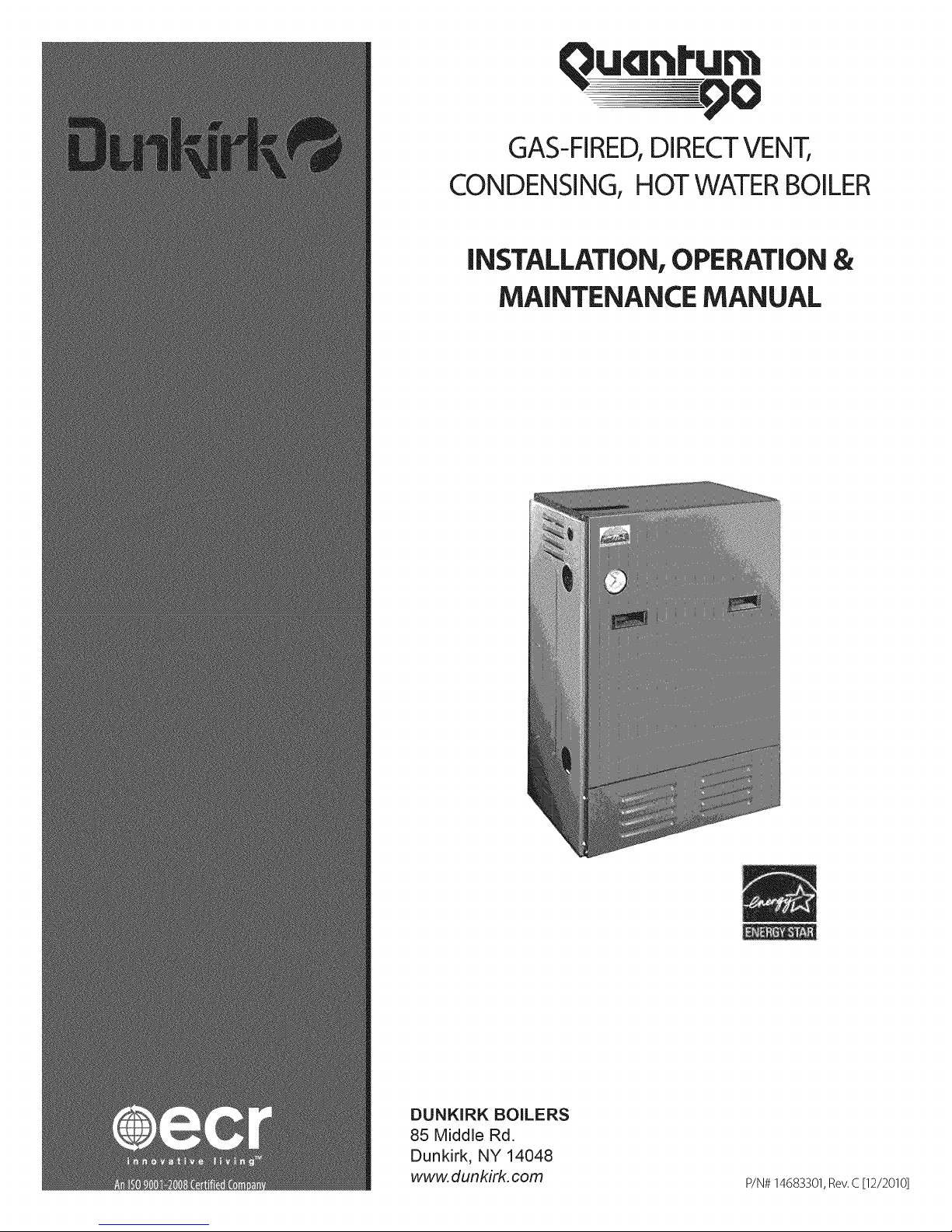
GAS-FIRED,DIRECTVENT,
CONDENSING, HOT WATER BOILER
INSTALLATION, OPERATION&
MAINTENANCE MANUAL
DUNKIRK BOILERS
85 Middle Rd.
Dunkirk, NY 14048
www. dunkirk, com
P/N# 14683301,Rev.C [12/2010]
90-75
90= 1 O0
These instructions
must be affixed on or
adjacent to the boiler.
iiiiiiiiiiiiiiiiiiiiiiiiiiiiiiiiiiiiiiiiiiiiiii
iiiiiiiiiiiiiiiiiiiiiiiiiiiiiiiiiiiiiiiiiiiiiiitheinstallation.
iiiiiiiiiiiiiiiiiiiiiiiiiiiiiiiiiiiiiiiiiiiiiiiSave this manual for reference.
Improper installation, adjustment, alteration,
service, or maintenance can cause injury or
property damage. Refer to this manual. For
assistance or additional information consult a
qualified installer, service agency, or the gas
supplier.
Read all instructions carefully before starting
Warnings and Safety Symbols ....................................................................................................... 3
Introduction ................................................................................................................................ 4
Boiler Ratings & Capacities ........................................................................................................... 5
Boilers For Use At High Altitude ..................................................................................................... 6
Rules For Safe Installation And Operation ....................................................................................... 8
Before Installing The Boiler ........................................................................................................... 8
Pladn( The Boiler ....................................................................................................................... 11
Near Boiler Piping ....................................................................................................................... 12
Combustion Air and Vent Pipe ...................................................................................................... 19
Gas Supply Piping ....................................................................................................................... 24
Electrical Wiring ......................................................................................................................... 26
Controls and Accessories ............................................................................................................. 30
Water Treatment & Freeze Protection ............................................................................................ 32
Start Up .................................................................................................................................... 34
Operating Instructions ................................................................................................................. 35
To Turn Off Gas To Appliance ........................................................................................................ 35
Check Out Procedure and Adjustment ........................................................................................... 36
Installation and Check-Out Certificate ............................................................................................ 40
Maintenance And Cleaning ........................................................................................................... 41
Detailed Sequence Of Operation ................................................................................................... 44
Troubleshooting .......................................................................................................................... 47
Differential Air Pressure Switch Check ........................................................................................... 55
IMPORTANT: THIS MANUAL MUST BE KEPT NEAR THE BOILER FOR FUTURE REFERENCE!!
Indicates an imminently hazardous situation
which, if not avoided, WILL result in death,
serious injury or substantial property damage,
which, ifn ot avoid ed, mayresu It in death,
serious injury or substantial property damage.
Indicates an imminently hazardous situation
which, if not avoided, may result in injury or
property damage.
Indicates information which should be
followed to ensure proper installation and
operation.
This appliance is a gas-fired direct vent hot water boiler with cast
aluminum boiler sections. A revolutionary cast aluminum heat
exchanger means better heat transfer and thermal storage than
sirnilarly sized cast iron boilers, which results in higher efiqciency.
The heating system water absorbs large amounts of heat from the
cast aluminum heat exchanger, cooling the flue gases and causing
condensation. Sealed combustion, premix gas burner, and low flame
temperature means drastically reduced CO and NOx emissions,
which contribute to a cleaner and healthier environment.
(sealedcombustion)and does not competewith building occupants
for fresh air. Sealedcombustion (also known as"directvent") is the
safestand best wayto obtainplentyofcleancombustion air. The
induced draft fan drawsin the outside combustion air,then takesthe
coolerfluegasesfrom the boilerunit and providesa positiveremoval
of thefluegasesfrom the building through inexpensiveand readily
availablePVCand CPVC pipes.
Thisappliance,unlikenormal residential atmospheric and induced
draft units, takes itscombustion airdirectly from the outdoors
Figure 1 - Boiler Dimensions
19 3/4"
(502ram}
ALTERNATE SUPP|.Y _,
& RETURN OPENINGS
CONN{::<7_ONS
_ROVID_DINEID_
gOILER(A@_[ [
RETURN
(1_/4' _4_P_ (3175_'nm) CONNECTIOP#S
PROVID£FJ INSIDE
4 V8"......(iu4.Smm)
22
(572mm)
JUNCTION BOX FOR _20 V POWER,
120 V CIRCULATOR LEADS, AND
24 V THERMOSTAT LEADS
VENT CONNECTION
CPvC) (50,Smm}
ALTERNATE GAS
39 112"
( _O05mm)
SUPPLY OPENING
ALTERNATE OPENING FOR
VENT TEE
IMPORTANT: Read the following instructions
COMPLETELY before installing!
( t 27r,nm)
VENT CONNECTION
(2" CPvC) (SO gin.' 0
DRA_N
CONDENSATE
DRAN FITIINO
(1/2" pro) O2.Tmm)
FRONT
(609.6mr,n}
2t"
24 _
(833 4ram)
VENT AND EXPANSION
TANK CONNECT{ON
FOR AIR
L
PROV_O_D iNS_g£ 80{LER C_81NE[)
13 ¸,1
(350.2mm)
BACK
TO_
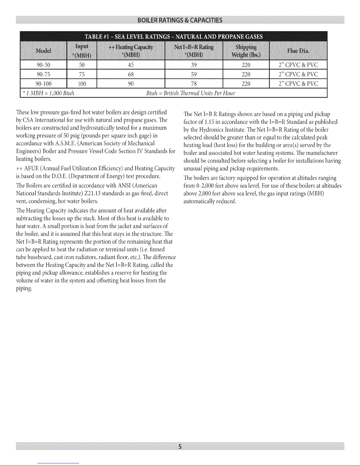
90-50 50 45 39 220 2" CPVC & PVC
90-75 75 68 59 220 2" CPVC & PVC
90-100 100 90 78 220 2" CPVC & PVC
*1MBH = 1,000 Btuh Btuh =British Thermal Units Per Hour
These low pressure gas-fired hot water boilers are design certified
by CSA International for use with natural and propane gases. The
boilers are constructed and hydrostatically tested for a rnaximurn
working pressure of 50 psig (pounds per square inch gage) in
accordance with A.S.M.E. (Arnerican Society of Mechanical
Engineers) Boiler and Pressure Vessel Code Section IV Standards for
heating boilers.
++ AFUE (Annual Fuel Utilization Efficiency) and Heating Capacity
is based on the D.O.E. (Departrnent of Energy) test procedure.
The Boilers are certified in accordance with ANSI (American
National Standards Institute) Z21.13 standards as gas-fired, direct
vent, condensing, hot water boilers.
The Heating Capacity indicates the arnount of heat available after
subtracting the losses up the stack. Most of this heat is available to
heat water. A srnall portion is heat frorn the jacket and surfaces of
the boiler, and it is assumed that this heat stays in the structure. The
Net I=B=R Rating represents the portion of the rernaining heat that
can be applied to heat the radiation or terminal units (i.e. finned
tube baseboard, cast iron radiators, radiant floor, etc.). Thedifference
between the Heating Capacity and the Net I=B=R Rating, called the
piping and pickup allowance, establishes a reserve for heating the
volurne of water in the systern and offsetting heat losses frorn the
piping.
The Net I=B R Ratings shown arebased on a piping and pickup
factor of 1.15 in accordance with the I=B=R Standard as published
by the Hydronics Institute. The Net I=B=R Rating of the boiler
selected should be greater than or equal to the calculated peak
heating load (heat loss) for the building or area(s) served by the
boiler and associated hot water heating systems. The rnanufacturer
should be consulted before selecting a boiler for installations having
unusual piping and pickup requirernents.
The boilers are factory equipped for operation at altitudes ranging
frorn 0-2,000 feet above sea level. For use of these boilers at altitudes
above 2,000 feet above sea level, the gas input ratings (MBH)
autornatically reduced.
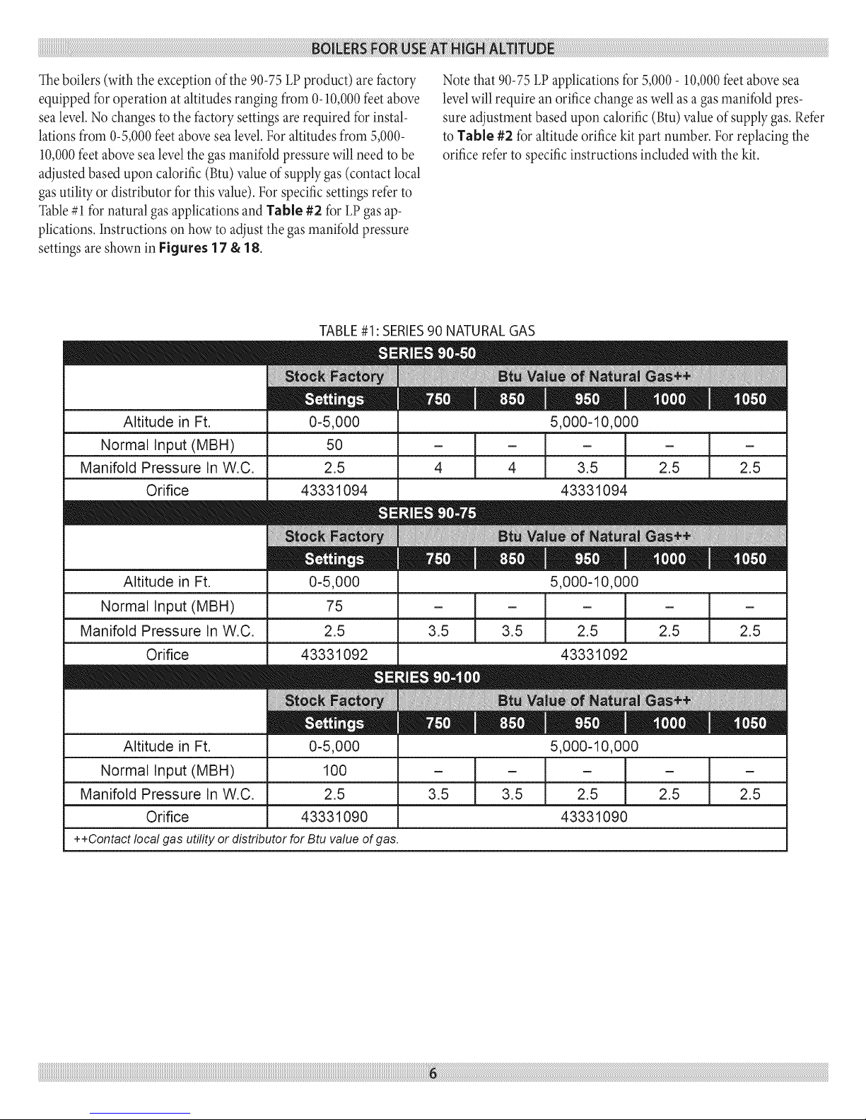
Theboilers(with the exceptionof the 90-75LPproduct) arefactory
equipped foroperation at altitudesranging from 0-10,000feetabove
sealevel.Nochanges to the factory settings arerequired for instal-
lationsfrom 0-5,000feet abovesealevel.Foraltitudes from 5,000-
10,000feetabovesealevel thegasmanifoldpressurewill need to be
adjustedbased upon calorific (Btu)valueof supplygas (contact local
gasutilityor distributor for thisvalue). For specificsettings refer to
Table#1 for natural gasapplicationsand Table #2 for LPgasap-
plications.Instructions on how to adjust the gasmanifold pressure
settings are shown in Figures 17 & 18.
TABLE#1: SERIES90 NATURAL GAS
Note that 90-75 LP applications for 5,000- 10,000 feet above sea
level will require an orifice change aswell as a gas manifold pres-
sure adjustment based upon calorific (Btu) value of supply gas. Refer
to Table #2 for altitude orifice kit part number. For replacing the
orifice refer to specific instructions included with the kit.
Altitude in Ft.
Normal Input (MBH)
Manifold Pressure In W.C.
Orifice
Altitude in Ft. 0-5,000 5,000-10,000
Normal Input (MBH) 75 - _ - - / - / -
Manifold Pressure In W.C. 2.5 3.5 / 3.5 2.5 / 2.5 / 2.5
Orifice 43331092 43331092
Altitude in Ft.
Normal Input (MBH)
Manifold Pressure In W.C.
Orifice
++Contact local gas utility or distributor for Btu value of gas.
0-5,000
50
2.5
43331094
0-5,000
100
2.5
43331090
5,000-10,000
- i - - i -
4 1 4 2.5 1 2.5
t t
3.5 3.5 2.5 2.5
- ]
3.5 _
43331094
5,000-10,000
-t
2.5
43331090
i_i_i_i_i_i_i_i_i_i_i_i_i_i_i_i_i_i_i_i_i_i_i_i_i_i_i_i_i_i_i_i_i_i_i_i_i_i_i_i_i_i_i_i_i_i_i
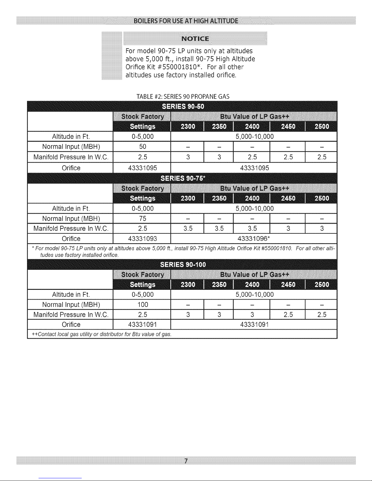
For model 90-75 LP units only at altitudes
above 5,000 ft., install 90-75 High Altitude
Orifice Kit #550001810*. For all other
altitudes use factory installed orifice.
TABLE#2: SERIES90 PROPANEGAS
Altitude in Ft.
Normal Input (MBH)
Manifold Pressure In W.C.
Orifice
Altitude in Ft.
Normal Input (MBH) - - [ - -
Manifold Pressure In W.C. 2.5 3.5 3.5 l 3 3
Orifice 43331093
* For model 90-75 LP units only at altitudes above 5,000 ft., install 90-75 High Altitude Orifice Kit #550001810. For all other alti-
tudes use factory installed orifice.
Altitude in Ft.
Normal Input (MBH)
Manifold Pressure In W.C.
Orifice
++Contact local gas utility or distributor for Btu value of gas.
0-5,000
50
2.5
43331095
0-5,000
75
0-5,000
100
2.5
43331091
5,000-10,000
[ - ]
3 3 2.5 2.5
43331095
5,000-10,000
- ]
3.5 l
43331096*
5,000-10,000
3 3 2.5 2.5
43331091
1. Readtheentireinstallationmanualbeforebeginningtheinstal-
lation.Failuretofollowtheserulesforsafeinstallationand
operationandtheseinstructionscouldcauseamalfunction
oftheboilerandresultindeath,seriousbodilyinjury,and/or
propertydamage.
2. Checkallapplicablestateandlocalbuildingcodesandutil-
itycompanyrequirementsbeforeinstallation.Theinstallation
mustconforrnwiththeserequirementsintheirentirety.Inthe
absenceofthesecodes,useNFPAInstallationCodesandgood
industrypractice.
3. Beforeservicingtheboiler-allowtheboilertocool.Always
shutoffanyelectricityandgassupplyconnectedtotheboiler
priortoservicing.
4. Inspectgaslineforleaks.
5. Becertaingasinputrateiscorrect.Overfiringmayresultin
earlyfailureoftheboilersections.Thismaycausedangerous
operation.Underfiringmayresultintoomuchairforthepre-
mixburnercausingpoororlossofcombustion.
6. Never vent the products of combustion from this boiler to an
enclosed space. Always vent to the outdoors. Never vent to
another room or to inside a building.
7. Be sure there is adequate outdoor air supply to boiler for com-
plete combustion.
8. Follow a regular service and maintenance schedule for efficient
and safe operation.
9. Keep boiler area clean of debris and flee of combustible and
flammable rnaterials.
10.
Proper through the wall or through the roof cornbustion vent-
ing shallbe in accordance with the materials and methods
described in this manual. Installation must complywith local
codes.
11.
This boiler and related hot water heating systems are not do it
yourself items. They must be installed and serviced by qualified
professionals.
This boiler has been equipped for residential
installations. If used for commercial
applications, any additional code requirements
must be adhered to for installation. This may
require additional controls including but not
limited to a low water cut off, a manual reset
high temperature limit, and wiring and/or
piping modifications. The manufacturer is not
responsible for any field installation changes
made to a boiler installation which are not
described or acknowledged in this manual.
Complete all of the following prior to installing the boiler.
Codes
This boiler product is a gas-fired, direct vent, condensing boiler and
must be installed to conforrn to the requirernents of the authority
having jursidiction or, in the absence of such requirements:
United States- National Fuel Gas Code (NFPA-54/ANSI Z223.1).
Canada- National Gas and Propane Installation Code, Can/CSA
B149.1.
Where required bythe authority havingjurisdiction, the installation
must conform to the Arnerican Societyof MechanicalEngineers
SafetyCode for Controls and SafetyDevicesfor AutomaticallyFired
Boilers,No.CSD-1.
iiiiiiiiiiiiiiiiiiiiiiiiiiiiiiiiiiiiiiiiiiiiii_
Important - In the state of Massachusetts
this product must be installedby a licensed
plumber or gas fitter and the installation must
be in accordance with 248 CHR.
Installers- Followlocal regulationswith respect to installation of
CO (Carbon Monoxide) Detectors. Followmaintenance recommen-
dations in this manual.
Installation Requirements Specific To The State Of
Massachusetts For Direct Vent, Mechanical Vent_ And
Domestic Hot Water Appliances
For all side wall horizontally vented gas fueled equiprnent installed
in every dwelling, building or structure used in whole or in part
for residential purposes, including those owned or operated by the
comrnonwealth and where the side wall exhaust vent terrnination is
less than seven (7) feet above finished grade in the area of the vent-
ing, including but not limited to decks and porches, the following
requirernents shall be satisfied:
. Installationof carbon rnonoxide detectors: atthe time ofinstal-
lation of the sidewall horizontal vented gasfueledequipment,
the installingplurnber or gasfittershallobserve that a hard
wired carbon rnonoxide detectorwith an alarrn and battery
back-up is installedon the floor levelwhere the gas equipment
isto be installed. In addition, the installing plurnber or gasfitter
shallobserve that a battery operated or hard wired carbon rnon-
oxidedetector with an alarrnisinstalled on each additional level
of thedwelling,building or structure servedby the side wall
horizontal vented gasfueledequipment. It shallbe the respon-
sibilityof the property owner to securethe servicesof qualified
licensed professionalsfor the installationof hard wired carbon
rnonoxide detectors.
a.
In the event that the side wall horizontally vented gas
fueled equiprnent is installed in a crawl space or an attic,
the hard wired carbon rnonoxide detector with alarm and
battery back-up may be installed on the next adjacent floor
level.
g.
In the event that the requirernents of this subdivision can
not be rnet at the time of cornpletion of installation, the
owner shall have a period of thirty (30) days to comply
with the above requirernents; provided, however, that dur-
ing said thirty (30) day period, a battery operated carbon
monoxide detector with an alarm shall be installed.
o
Approved carbon monoxide detectors: each carbon monoxide
detector as required in accordance with the above provisions
shall comply with NFPA720 and be ANSI/UL 2034 listed and
IAS certified.
3. Signage: a metal or plastic identification plate shall be perrna-
nently mounted to the exterior of the building at a rninimum
height of eight (8) feet above grade directly in line with the
exhaust vent terminal for the horizontally vented gas fueled
heating appliance or equipment. The sign shall read, in print
size no less than one-half (112)inch in size, "gas vent directly
below. Keep clear of all obstructions".
4. Inspection: the state or local gas inspector of the side wall
horizontally vented gas fueled equipment shall not approve
the installation unless, upon inspection, the inspector observes
carbon monoxide detectors and signage installed in accordance
with the provisions of 248 CMR 5.08(2)(A)1 through 4.
5. Product-approved vent/air-intake: a product-approved vent ter-
minal must be used and, if applicable, a product-approved air
intake must be used. Installation shall be in strict compliance
with the rnanufacturer's instructions.
o
Installation instructions: a copy of allinstallation instructions
for all product approved side wall horizontally vented gas fueled
equipment, all venting instructions, all parts lists for venting
instructions, and/or all venting design instructions shall remain
with the appliance or equipment at the completion of the instal-
lation.
Boiler Sizing
Checktobe sure you haveselected the boiler with the proper capac-
itybeforestarting the installation. TheI=B=RRatingofthe boiler
selectedshould be greater than or equal to the calculatedpeak heat-
ing load (heat loss)for the building or area(s) served by the boiler
and associatedhot waterheating systems.Seethe table"BOILER
RATINGSAND CAPACITIES"(page5 of this docurnent).
Heat losscalculationsshould be based on approved industry meth-
ods.
Considerations For Boiler Location
Before selecting a location for the boiler, the following should be
considered. Each boiler considered.
•Suppliedwith the correct type of gas(natural gasor pro-
pane).
• Connected to a suitable cornbustion air intake piping sys-
tern to supply the correct amounts of fresh (outdoor) air
for cornbustion, refer to Combustion Air And Vent Pipe
section (near center of this manual) for details.
• Connected to a suitable venting systern to remove the
hazardous products of gas combustion, refer to Cornbus-
tion Air And Vent Pipe section (page 19 of this rnanual) for
details.
•Connectedto asuitablehot water heating systern.
•Suppliedwith a suitableelectricalsupplyfor allboilerrno-
tors and controls.
• Connected to a properly located therrnostat or operating
control. (not included with boiler)
•Placedon levelsurface (rnust NOT be installedon carpet-
ing)
•Condensate drain line must bepitched down to floor drain
or externalcondensate purnp with reservoir at1A"per foot
(woodfrarneor blocksrnay beused to raise boiler).
Locating The Boiler
1. Selecta locationwhich is level,central to the piping systerns
served and as closeto the vent and air intaketerrninals aspos-
sible.
2. Accessibility clearances, if more stringent (i.e. larger clearances)
than required fire protection clearances, rnust be used for the
boiler installation. Accessibility clearances rnay be achieved
with the use of removable walls or partitions.
3. The boiler is approved for installation in closets and on com-
bustible floors. This boiler shall NOT be installed on carpeting.
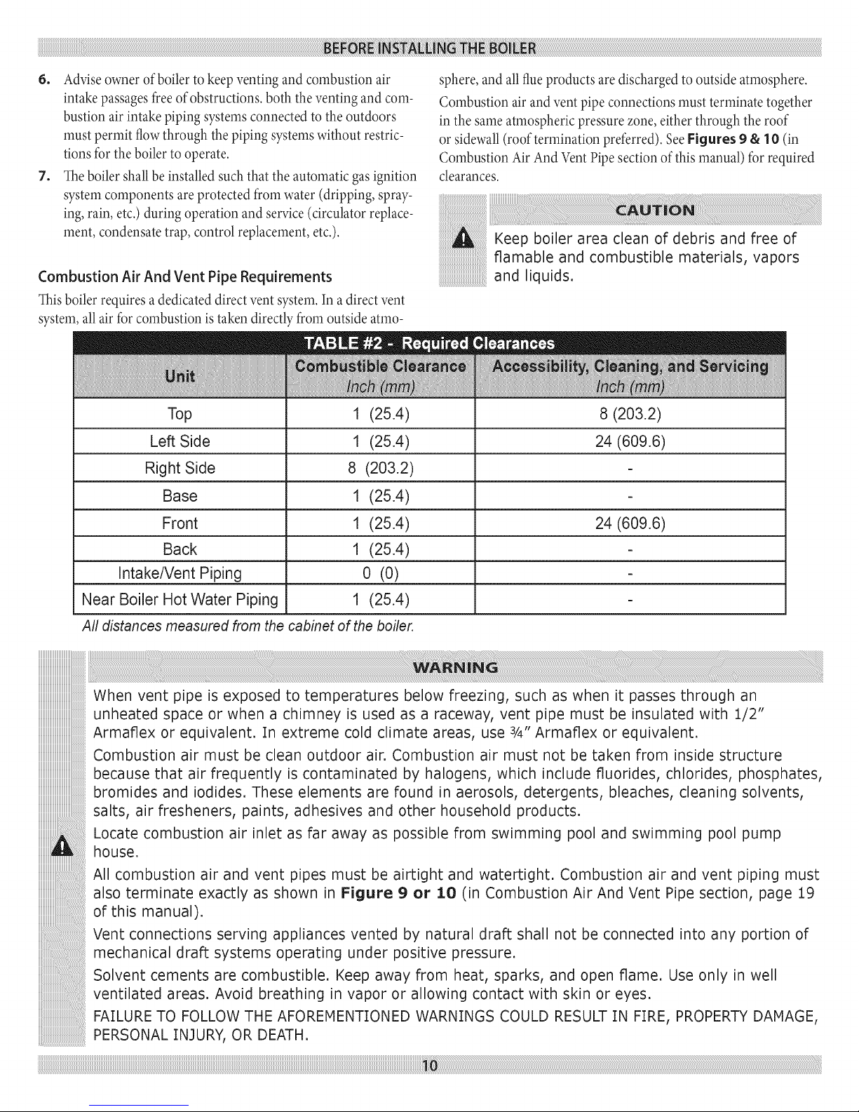
4. The clearances shown in Table #2 indicate required clearances.
A rninimurn 1" clearance rnust be rnaintained between corn-
bustible construction and each of the left, top and back surfaces
of the boiler. A rninimum 8" clearance is required on the right
side, to allow roorn for the inlet air pipe. An 18" clearance rnust
be rnaintained at a side where passage is required to access an-
other side for cleaning or servicing, inspection or replacernent
of any parts that norrnally rnay require such attention. Allow at
least 24" at the front and left side and 8" at the top for servicing.
No clearances are required to venting or cornbustion air intake
piping.
5. Equipment shall be installed in a location which facilitates the
operation of venting and cornbustion air intake piping systems
as described in this rnanual.
6. Adviseownerofboilertokeepventingandcombustionair
intakepassagesfreeofobstructions,boththeventingandcorn-
bustionairintakepipingsystemsconnectedtotheoutdoors
rnustpermitflowthroughthepipingsysternswithoutrestric-
tionsfortheboilertooperate.
7. Theboilershallbeinstalledsuchthattheautomaticgasignition
systerncornponentsareprotectedfromwater(dripping,spray-
ing,rain,etc.)duringoperationandservice(circulatorreplace-
rnent,condensatetrap,controlreplacernent,etc.).
Combustion Air And Vent Pipe Requirements
This boiler requires adedicated direct vent systern. In a direct vent
systern, all air for cornbustion is taken directly frorn outside atrno-
Top 1 (25.4) 8 (203.2)
Left Side 1 (25.4) 24 (609.6)
Right Side 8 (203.2)
sphere,and all flue products are discharged to outside atmosphere.
Cornbustion air and ventpipe connections rnust terrninate together
in the sameatmosphericpressure zone, either through the roof
or sidewall(roof termination preferred). SeeFigures 9 & 10 (in
Combustion Air AndVentPipe sectionofthis manual) for required
clearances.
Keep boiler area clean of debris and free of
flamable and combustible materials, vapors
and liquids.
Base 1 (25.4)
Front 1 (25.4) 24 (609.6)
Back 1 (25.4)
Intake/Vent Piping 0 (0)
Near Boiler Hot Water Piping 1 (25.4)
All distances measured from the cabinet of the boiler.
When vent pipe is exposed to temperatures below freezing, such as when it passes through an
unheated space or when a chimney is used as a raceway, vent pipe must be insulated with :!./2"
Armaflex or equivalent. In extreme cold climate areas, use 3/4" Armaflex or equivalent.
Combustion air must be clean outdoor air. Combustion air must not be taken from inside structure
because that air frequently is contaminated by halogens, which include fluorides, chlorides, phosphates,
bromides and iodides. These elements are found in aerosols, detergents, bleaches, cleaning solvents,
salts, air fresheners, paints, adhesives and other household products.
Locate combustion air inlet as far away as possible from swimming pool and swimming pool pump
house.
All combustion air and vent pipes must be airtight and watertight. Combustion air and vent piping must
also terminate exactly as shown in Figure 9 or 10 (in Combustion Air And Vent Pipe section, page 19
of this manual).
Vent connections serving appliances vented by natural draft shall not be connected into any portion of
mechanical draft systems operating under positive pressure.
Solvent cements are combustible. Keep away from heat, sparks, and open flame. Use only in well
ventilated areas. Avoid breathing in vapor or allowing contact with skin or eyes.
FAILURE TO FOLLOW THE AFOREMENTIONED WARNINGS COULD RESULT IN FIRE, PROPERTY DAMAGE,
PERSONAL INJURY, OR DEATH.
Condensate Drain Requirements
Condensate drain line to be pitched down to floordrain atamini-
rnurnof 1A"per foot.An external condensatepump (not furnished)
maybe used if floordrain isnot available.Thecondensate pump
must be designed for fluegas condensate application.
iiiiiiiiiiiiiiiiiiiiiiiiiiiiiiiiiiiiiiiiiiiiii_
:[.Condensatetrap bu,t ntothebo ler,an
external trap is not required and should not
2. Wood frame or blocks may be used to raise
the boiler to maintain drain pitch or to be
above external condensate pump reservoir.
3. There is a :[::[5 Volt AC receptacle provided
on the service switch junction box which is
located at the boiler right side, to provide
power for an external condensate pump (if
needed).
Foundation Requirements
Boilermust be placedon levelsurface.Boileris NOT to be installed
on carpeting.
iiiiiiiiiiiiiiiiiiiiiiiiiiiiiiiiiiiiiiiiiiiiii_
If boiler is not level condensate drain lines
will not function properly. Adjustable feet are
located on the boiler to makeup for minor
surface irregularities or tilt.
Wood frame or blocks may be used to raise
boiler to maintain drain pitch or to be above
external co ndensate pum p rese rv oir.
Removal of Existing Boiler From Common Vent System
When an existing boiler is rernoved from a common venting system,
the comrnon venting systern is likely to be too large for proper vent-
ing of the appliances remaining connected to it. At the time of re-
moval of an existing boiler, the following steps shall be followed with
each appliance rernaining connected to the common venting systern
placed in operation, while the other appliances rernaining connected
to the cornmon venting systern are not in operation.
1. Seal any unused openings in the comrnon venting systern.
2. Visually inspect the venting system for proper size and hori-
zontal pitch and deterrnine there isno blockage, or restrictions,
leakage, corrosion and other deficiencies which could cause an
unsafe condition.
3. In-so-far as is practical, close all building doors and windows
and all doors between the space in which the appliances remain-
ing connected to the common venting system are located and
other spaces of the building. Turn on clothes dryer and any ap-
pliance not connected to the common venting systern. Turn on
any exhaust fans, such as range hoods and bathroom exhaust, so
they will operate at maximum speed. Do not operate a summer
exhaust fan. Close fire darnpers.
4. Place in operation the appliance being inspected. Follow the
lighting instructions. Adjust therrnostat so appliances will oper-
ate continuously.
5. Test for spillage at the draft hood relief opening after 5minutes
of main burner operation. Use the flame of a match or candle,
or the smoke frorn acigarette, cigar or pipe.
6. After it has been deterrnined that each appliance remaining
connected to the common venting systern properly vents when
tested as outlined above, return doors, windows, exhaust fans,
fire place dampers, and any other gas-burning appliance to their
previous condition of use.
7. Any improper operation of the comrnon venting systern should
be corrected so the installation conforms with the National Fuel
Code, NFPA-54/ANSI -Z223.1 and/or the Natural Gas and
Propane Installation Code, CAN/CSA B149.1.. When resizing
any portion of the common venting systern, the comrnon vent-
ing system should be resized to approach the minimum size as
deterrnined using the appropriate tables in Chapter 13 of the
National Fuel Gas Code, NFPA-54/ANSI- Z223.1 and/or the
Natural Gas and Propane Installation Code, CAN/CSA B149.1.
The boiler should be placed to provide the most direct connections
to the combustion air, vent and systern piping as possible.
Place crated boiler as close to selected location as possible and
uncrate boiler. The uncrated boiler may be moved into position with
an appliance dolly or 2-wheel hand truck. The dolly or hand truck
should be inserted under the left hand side of the boiler. It is possible
to slide the boiler for a short distance on a smooth floor or surface.
Refer to manual section "locating the
boiler" (page 9 of this manual), for required
clearances for servicing and maintenance.
When the installation of the boiler is for a new heating system, first
install all of the radiation units (panels, radiators, baseboard, or tub-
ing) and the supply and return mains. After all heating system piping
and components have been installed, make final connection of the
system piping to the boiler. A hot water boiler installed above radia-
tion level, or as required by the Authority having jurisdiction, must
be equipped with a low water cut off&vice. A periodic inspection
is necessary for flushing of float type devices, per low water cut off
manufacturers specific instructions.
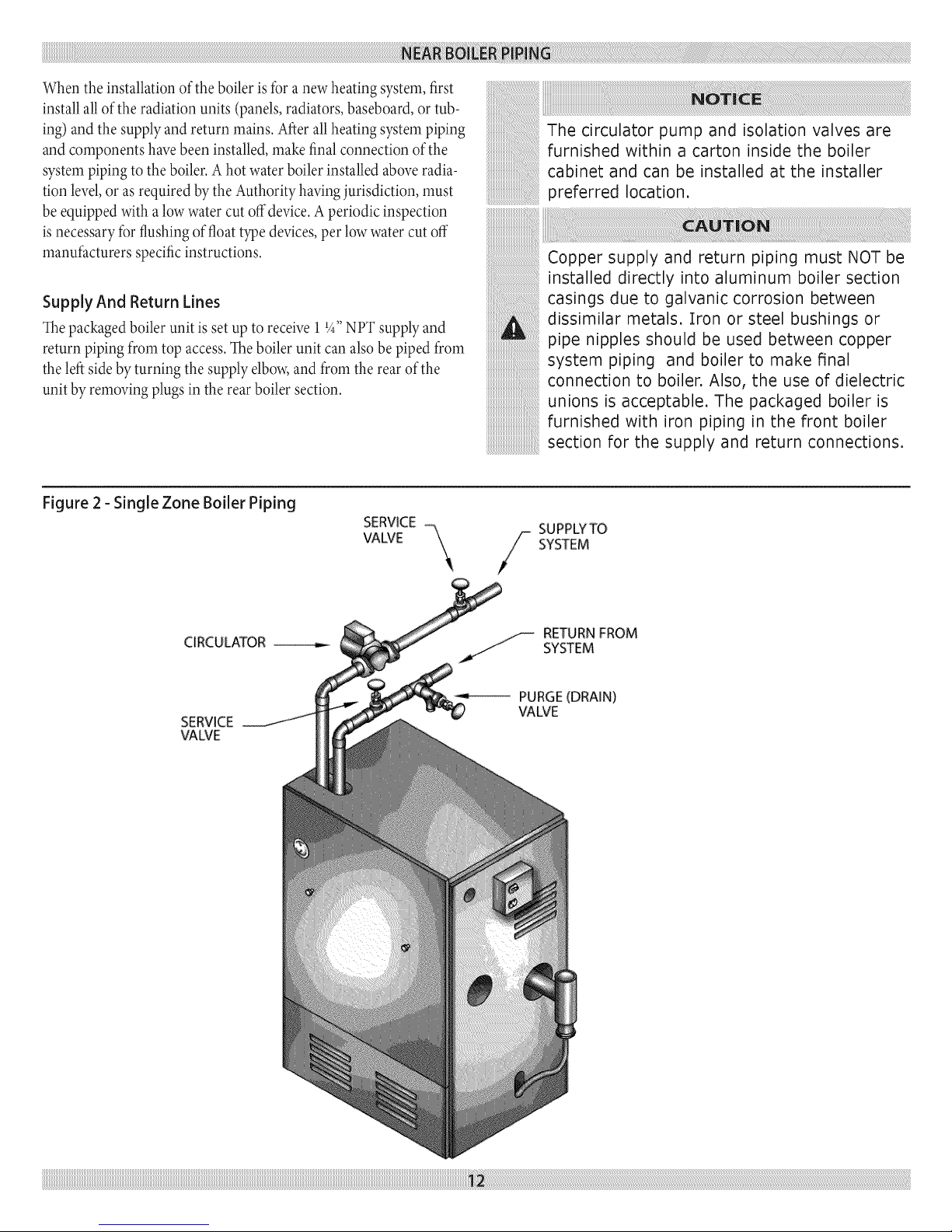
Supply And Return Lines
The packaged boiler unit is set up to receive 11_,,NPT supply and
return piping from top access. The boiler unit can also be piped from
the left side by turning the supply elbow, and from the rear of the
unit by removing plugs in the rear boiler section.
Figure 2 - Single Zone Boiler Piping
SERVICE -
The circulator pump and isolation valves are
furnished within a carton inside the boiler
cabinet and can be installed at the installer
preferred location.
Copper supply and return piping must NOT be
installed directly into aluminum boiler section
casings due to galvanic corrosion between
dissimilar metals. Iron or steel bushings or
pipe nipples should be used between copper
system piping and boiler to make final
connection to boiler. Also, the use of dielectric
unions is acceptable. The packaged boiler is
furnished with iron piping in the front boiler
section for the supply and return connections.
SUPPLYTO
CIRCULATOR
SERVICE
VALVE
VALVE
-SYSTEM
_.jj-- RETURN FROM
SYSTEM
PURGE(DRAIN)
VALVE
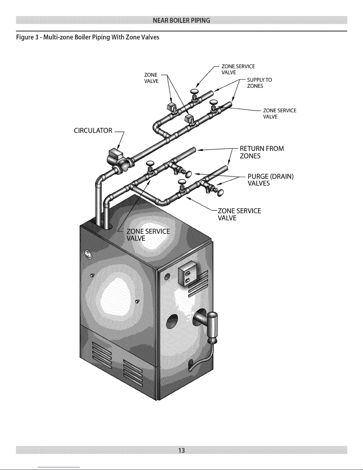
Figure 3 - Multi-zone Boiler Piping With Zone Valves
ZONE
\JAWE
CIRCU LATOR
ZONE SERVICE
VALVE
SUPPLYTO
ZONES
ZONESERVICE
VAWE
FROM
ZONES
PURGE (DRAIN)
VALVES
VALVE
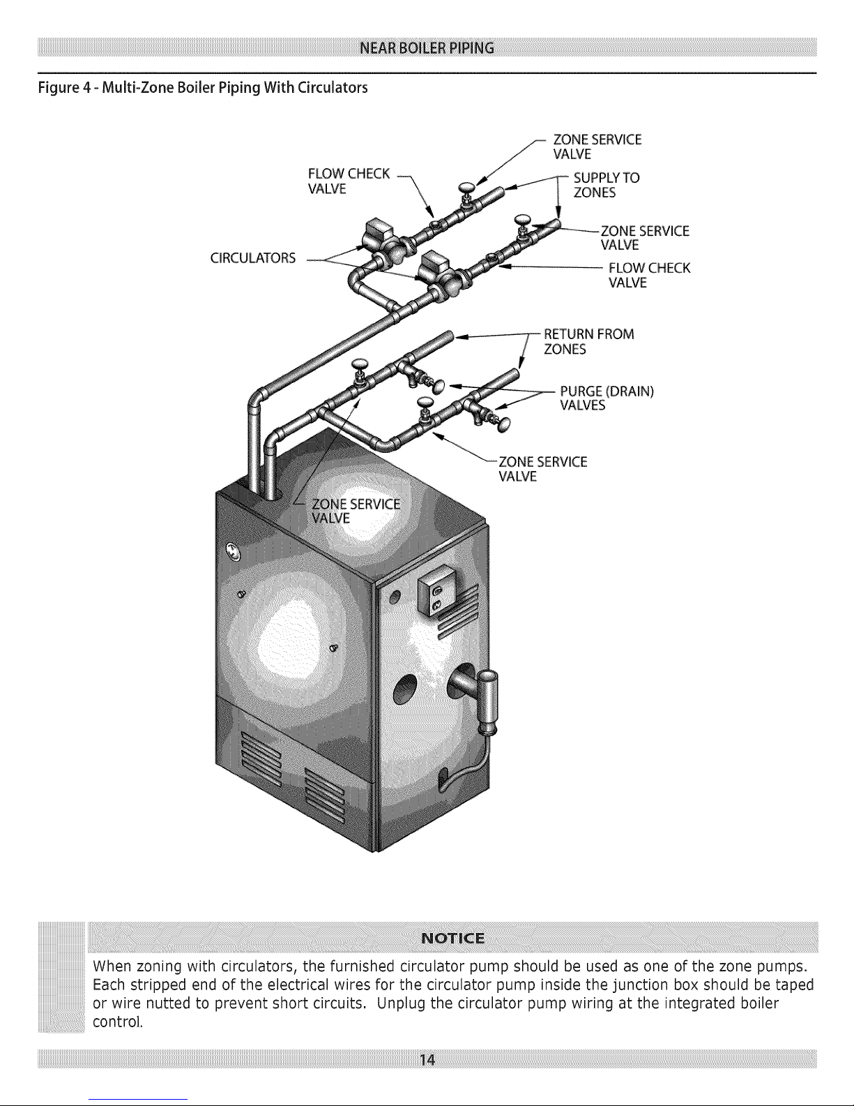
Figure4-Multi-ZoneBoilerPipingWithCirculators
FLOW CHECK
VALVE "\
CIRCULATORS
ZONE SERVICE
VALVE
SUPPLYTO
ZONES
_WE
FLOW CHECK
VALVE
RETURNFROM
ZONES
PURGE(DRAIN)
VALVES
SERVICE
VALVE
When zoning with circulators, the furnished circulator pump should be used as one of the zone pumps.
Each stripped end of the electrical wires for the circulator pump inside the junction box should be taped
or wire nutted to prevent short circuits. Unplug the circulator pump wiring at the integrated boiler
control.
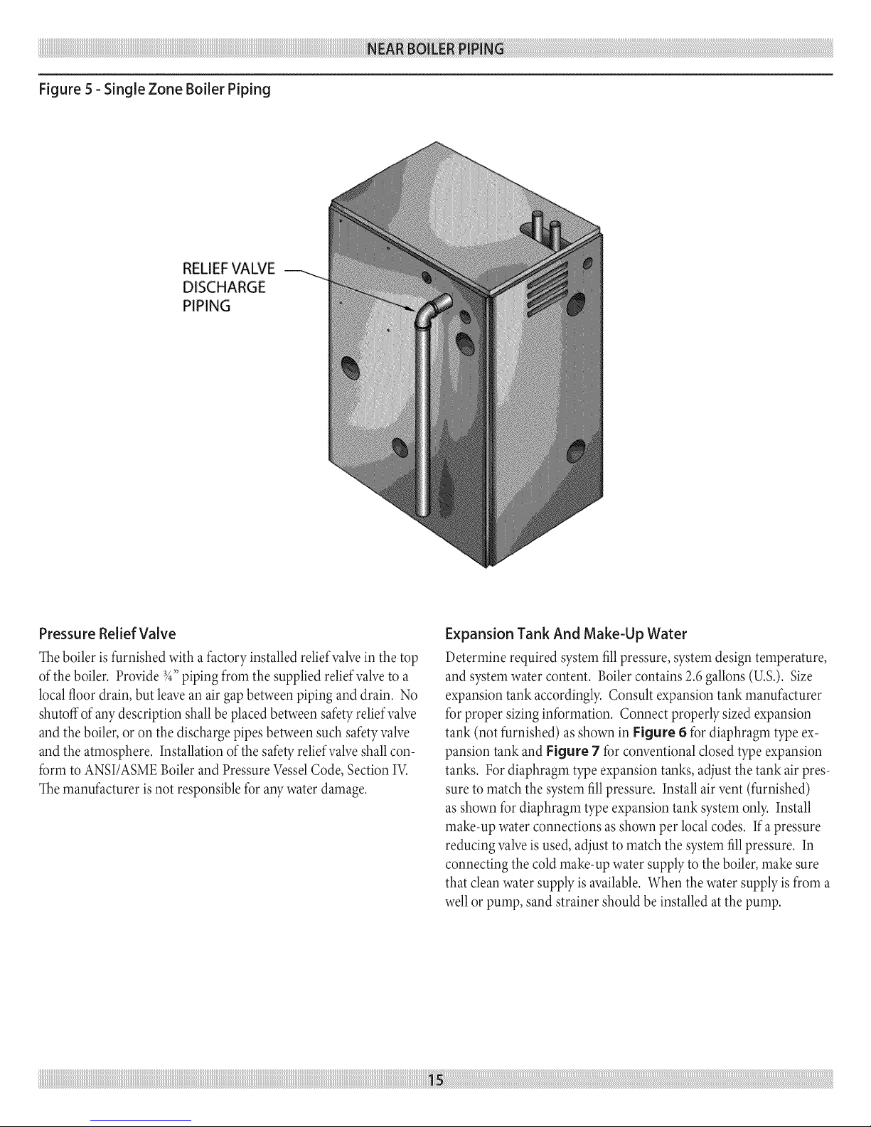
Figure5-SingleZoneBoilerPiping
DISCHARGE
PIPING
PressureReliefValve
Theboileris furnished with a factoryinstalled reliefvalvein the top
ofthe boiler. Provide3_,,piping frorn the supplied reliefvalveto a
localfloordrain, but leavean air gapbetweenpiping and drain. No
shutoffof any description shallbe placed betweensafetyreliefvane
and the boiler,oron the discharge pipes between such safetyvalve
and the atmosphere. Installationofthe safetyreliefvalveshall con-
forrn to ANSI/ASMEBoilerand Pressure VesselCode, Section IV.
Themanufacturer isnot responsiblefor aW water damage.
Expansion Tank And Make-Up Water
Deterrnine required systern fill pressure, systern design ternperature,
and systern water content. Boiler contains 2.6 gallons (U.S.). Size
expansion tank accordingly. Consult expansion tank manufacturer
for proper sizing information. Connect properly sized expansion
tank (not furnished) as shown in Figure 6 for diaphragm type ex-
pansion tank and Figure 7 for conventional closed type expansion
tanks. For diaphragm type expansion tanks, adjust the tank air pres-
sure to match the systern fill pressure. Install air vent (furnished)
as shown for diaphragm type expansion tank systern only. Install
make-up water connections as shown per local codes. If a pressure
reducing valve is used, adjust to match the systern fill pressure. In
connecting the cold make-up water supply to the boiler, make sure
that clean water supply is available. When the water supply is from a
well or pump, sand strainer should be installed at the pump.

Figure 6 - Diaphragm Type Expansion Tank Piping
MANUAL FILL
VALVE
AUTOMATIC AIR
VENT _
3/4"xI/8" BUSHING _
3/4" TEE_
3/4" NIPPLE (FURNISHED
AND INSTALLED ON
PACKAGED BOILER)
3/4" STREET ELL*
COLD
WATER
FILL
FURNISHED IN
PARTS BAG.
DIAPHRAGM TYPE
EXPANSION TANK
COMBINATION QUICK FILL
VALVE, STRAINER, CHECK
VALVE AND PRESSURE
REDUCING VALVE
iiiiiiiiiiiiiiiiiiiiiiiiiiiiiiiiiiiiiiiiiiiiiiiiiiiiiiiiiiiiiiiiiiiiiiiiiiiiiiiiiiiiiiiiiiiiiiiiiiiiiiiiiiiiiiiiiiiiiiiiiiiiiiiiiiiiiiiiiiiiiiiiiiiiiiiiiiiiiiiiiiiiiiiiiiiiiiiiiiiiiiiiiiiiiiiiiiiiiiiiiiiiiiiiiiiiiiiiiiiiiiiiiiiiiiiiiiiiiiiiiiiiiiiiiiiiiiiiiiiiiiiiiiiiiiiiiiiiiiiiiiiiiiiiiiiiiiiiiiiiiiiiiiiiiiiiiiiiiiiiiiiiiiiiiiiiiiiiiiiiiiiiiiiiiiiiiiiiiiiiiiiiiiiiiiiiiiiiiiiiiiiiiiiiiiiiiiiiiiiiiiiiiiiiiiiiiiiiiiiiiiiiiiiiiiiiiiiiiiiiiiiiiiiiiiiiiiiiiiiiiiiiiiiiiiiiiiiiiiiiiiiiiiiiiiiiiiiiiiiiiiiiiiiiiiiiiiiiiiiiiiiiiiiiiiiiiiiiiiiiiiiiiiiiiiiiiiiiiiiiiiiiiiiiiiiiiiiiiiiiiiiiiiiiiiiiiiiiiiiiiiiiiiiiiiiiiiiiiiiiiiiiiiiiiiiiiiiiiiiiiiiiiiiiiiiiiiiiiiiiiiiiiiiiiiiiiiiiiiiiiiiiiiiiiiiiiiiiiiiiiiiiiiiiiiiiiiiiiiiiiiiiiiiiiiiiiiiiiiiiiiiiiiiiiiiiiiiiiiiiii_ii_ii_i_i_iiliiiliiiiiiiiiiiiiiiiliiiiiiiiiiiiiiiiiiiiiiiliiiiiiiiiiiiiiiiiiiiiiiliiiiiiiiiiiiiiiiiiiiiiiliiiiiiiiiiiiiiiiiiiiiiiliiiiiiiiiiiiiiiiiiiiiiiliiiiiiiiiiiiiiiiiiiiiiiliiiiiiiiiiiiiiiiiiiiiiiliiiiiiiiiiiiiiiiiiiiiiiliiiiiiiiiiiiiiiiiiiiiiiliiiiiiiiiiiiiiiiiiiiiiiliiiiiiiiiiiiiiiiiiiiiiiliiiiiiiiiiiiiiiiiiiiiiiliiiiiiiiiiiiiiiiiiiiiiiliiiiiiiiiiiiiiiiiiiiiiiliiiiiiiiiiiiiiiiiiiiiiiliiiiiiiiiiiiiiiiiiiiiiiliiiiiiiiiiiiiiiiiiiiiiiliiiiiiiiiiiiiiiiiiiiiiiliiiiiiiiiiiiiiiiiiiiiiiliiiiiiiiiiiiiiiiiiiiiiiliiiiiiiiiiiiiiiiiiiiiiiliiiiiiiiiiiiiiiiiiiiiiiliiiiiiiiiiiiiiiiiiiiiiiliiiiiiiiiiiiiiiiiiiiiiiliiiiiiiiiiiiiiiiiiiiiiiliiiiiiiiiiiiiiiiiiiiiiiliiiiiiiiiiiiiiiiiiiiiiiliiiiiiiiiiiiiiiiiiiiiiiliiiiiiiiiiiiiiiiiiiiiiiliiiiiiiiiiiiiiiiiiiiiiiliiiiiiiiiiiiiiiiiiiiiiiliiiiiiiiiiiiiiiiiiiiiiiliiiiiiiiiiiiiiiiiiiiiiiliiiiiiiiiiiiiiiiiiiiiiiliiiiiiiiiiiiiiiiiiiiiiiliiiiiiiiiiiiiiiiiiiiiiiliiiiiiiiiiiiiiiiiiiiiiiliiiiiiiiiiiiiiiiiiiiiiiliiiiiiiiiiiiiiiiiiiiiiiliiiiiiiiiiiiiiiiiiiiiiiliiiiiiiiiiiiiiiiiiiiiiiliiiiiiiiiiiiiiiiiiiiiiiliiiiiiiiiiiiiiiiiiiiiiiliiiiiiiiiiiiiiiiiiiiiiiliiiiiiiiiiiiiiiiiiiiiiiliiiiiiiiiiiiiiii!_!_!_¸_
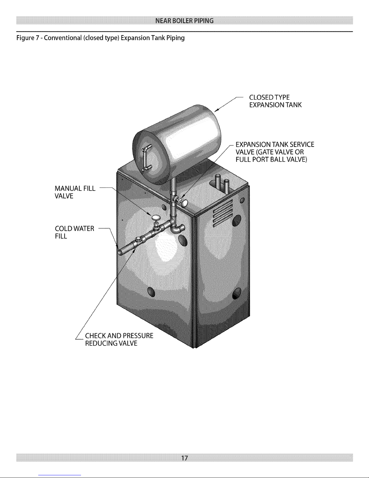
Figure 7 - Conventional (closed type) Expansion Tank Piping
MANUAL FILL
VALVE
CLOSEDTYPE
EXPANSION TANK
EXPANSION TANK SERVICE
VALVE (GATE VALVE OR
FULL PORT BALL VALVE)
COLD WATER
FILL
CHECK AND PRESSURE
REDUCING VALVE
 Loading...