

Dunkirk 3EW.65T, 3EW.65Z, 3EW.75, 3EW.75T, 3EW.75Z Installation Guide
...
Hodels
SERIES
3EW,65
3EW,75
3EWI,O0
4EW,90
4EW1,25
4EW1,50
SEW1,20
5EW1,75
OIL-FIRED CAST IRON
HOT WATER
INSTALLATION, OPERATION
& HAINTENANCE HANUAL
,?__,_g_,',,_& .......................................................
_!._,_,, ,
_',!_,._;_#_ ::::::::::::::::::::::::::::::.............
_i:_'_,_;_! ..........................................
_._,_.',_rL_
,
dS
Maximum Allowable
Working Pressure 50 psi.
Manufactured by:
ECR international, inc.
220! DwyerAwnue. Utica NY 13501
web s_te www ecnnternat/onal corn
H
P/N# 240009549, Rev B [10/2012]
Safety Notices .............................................. 2
Boiler Ratings And Capacities ......................... 3
Fresh Air For Combustion ............................... 7
System Piping .............................................. 9
Chimney And Chimney Connections .............. 16
Typical Chimney Connection ......................... 17
Electrical Connections ................................. 18
Filling The Boiler ....................................... 19
Operating The Boiler ................................. 20
Checking And Adjusting Controls .................. 23
Maintenance .............................................. 24
Oil Boiler Cleaning Instructions .................... 25
Oil Burner Cleaning ..................................... 26
Service Hints ............................................. 27
Electrical Wiring ......................................... 28
Equipment And Optional Accessories ............. 29
Introduction
Empire Water boiler is a natural draft oil fired hot water
boiler comprised of cast iron sections. Empire Water
boiler is available with 3, 4, or 5 cast iron sections. These
sections are held together by cast iron push nipples.
Empire Water boiler is capable of firing #2 fuel oil from
0.65 gph up to 2.00 gph. All packaged boilers include a
swing door, Honeywell limit, temperature and pressure
gauge, safety relief valve, drain valve, flue brush, and extra
boiler tap for expansion tank or air elimination.
Boiler installation shall be completed by qualified agency.
Become familiar with symbols identifying
potential hazards.
This is the safety alert symbol. Symbol alerts you
to potential personal injury hazards. Obey all safety
messages following this symbol to avoid possible injury or
death.
Indicates a hazardous situation which, if not avoided,
WILL result in death or serious injury
Indicates a hazardous situation which, if not avoided,
could result in death or serious injury.
CAUTION
Indicates a hazardous situation which, if not avoided,
could result in minor or moderate injury.
Used to address practices not related to personal
injury.
iiiiiiiiiiiiiiiiiiiiiiiiiiiiiiiiiiiiiiiiiiiiiiiiiiiiiiiiiiiiiiiiiiiiiiiiiiiiiiiiiiiiiiiiiiiiiiiiiiiiiiiiiiiiiiiiiiiiiiiiiiiiiiiiiiiiiiiiiiiiiiiiiiiiiiiiiiiiiiiiiiiiiiiiiiiiiiiiiiiiiiiiiiiiiiiiiiiiiiiiiiiiiiiiiiiiiiiiiiiiiiiiiiiiiiiiiiiiiiiiiiiiiiiiiiiiiiiiiiiiiiiiiiiiiiiiiiiiiiiiiiiiiiiiiiiiiiiiiiiiiiiiiiiiiiiiiiiiiiiiiiiiiiiiiiiiiiiiiiiiiiiiiiiiiiiiiiiiiiiiiiiiiiiiiiiiiiiiiiiiiiiiiiiiiiiiiiiiiiiiiiiiiiiiiiiiiiiiiiiiiiiiiiiiiiiiiiiiiiiiiiiiiiiiiiiiiiiiiiiiiiiiiiiiiiiiiiiiiiiiiiiiiiiiiiiiiiiiiiiiiiiiiiiiiiiiiiiiiiiiiiiiiiiiiiiiiiiiiiiiiiiiiiiiiiiiiiiiiiiiiiiiiiiiiiiiiiiiiiiiiiiiiiiiiiiiiiiiiiiiiiiiiiiiiiiiiiiiiiiiiiiiiiiiiiiiiiiiiiiiiiiiiiiiiiiiiiiiiiiiiiiiiiiiiiiiiiiiiiiiiiiiiiiiiiiiiiiiiiiiiiiiiiiiiiiiiiiiiiiiiiiiiiiiiiiiiiiiiiiiiiiiiiiiiiiiiiiiiiiiii!!!_i;ii;ii;ii;ii;ii;ii;ii;ii;ii;ii;ii;ii;ii;ii;ii;ii;ii;ii;ii;ii;ii;ii;ii;ii;ii;ii;ii;ii;ii;ii;ii;ii;ii;ii;ii;ii;ii;ii;ii;ii;ii;ii;ii;ii;ii;ii;ii;ii;ii;ii;ii;ii;ii;ii;ii;ii;ii;ii;ii;ii;ii;ii;ii;ii;ii;ii;ii;ii;ii;ii;ii;ii;ii;ii;ii;ii;ii;ii;ii;ii;ii;ii;ii;ii;ii;ii;ii;ii;ii;ii;ii;ii;ii;ii;ii;ii;ii;ii;ii;ii;ii;ii;ii;ii;ii;ii;ii;ii;ii;ii;ii;ii;ii;ii;ii;ii;ii;ii;ii;ii;ii;ii;ii;ii;ii;ii;ii;ii;ii;ii;ii;ii;ii;ii;ii;ii;ii;ii;ii;ii;ii;ii;ii;ii;ii;ii;ii;ii;ii;ii;ii;ii;ii;ii;ii;ii;ii;ii;ii;ii;ii;ii;ii;ii;ii;ii;ii;ii;ii;ii;ii;ii;ii;ii;ii;ii;ii;ii;ii;ii;ii;ii;ii;ii;ii;ii;ii;ii;ii;ii;ii;ii;ii;ii;ii;ii;ii;ii;ii;ii;ii;ii;ii;ii;ii;ii;ii;ii;ii;ii;ii;ii;ii;ii;ii;ii;ii;ii;ii;ii;ii;ii;ii;ii;ii;ii;ii;ii;ii;ii;ii;ii;ii;ii;ii;ii;ii;ii;ii;ii;ii;ii;ii;ii;ii;ii;ii;ii;ii;ii;ii;ii;ii;ii;ii;ii;ii;ii;ii;ii;ii;ii;ii;ii;ii;ii;ii;ii;ii;ii;ii;ii;ii;ii;ii;ii;ii;ii;ii;ii;ii;ii;ii;ii;ii;ii;ii;ii;ii;ii;ii;ii;ii;ii;ii;ii;ii;ii;ii;ii;ii;ii;ii;ii;ii;ii;ii;ii;ii;ii;ii;ii;ii;ii;ii;ii;ii;ii;ii;ii;ii;ii;ii;ii;ii;ii;ii;ii;ii;ii;ii;ii;ii;ii;ii;ii;ii;ii;ii;ii;ii;ii;ii;ii;ii;ii;ii;ii;ii;ii;ii;ii;ii;ii;ii;ii;ii;ii;ii;ii;ii;ii;ii;ii;ii;ii;ii;ii;ii;ii;ii;ii;ii;ii;ii;ii;ii;ii;ii;ii;_i_!
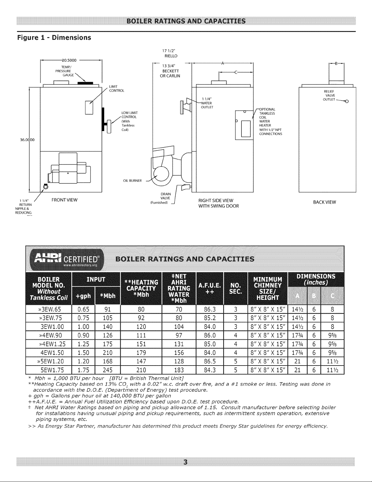
Figure 1 = Dimensions
2&5000 --
TEMR/
PRESSUiqE
GAUGE "_'_
36.01 iO0
I
LIMIT
/ CONTROL
I_/CO NTROL
LOW LIMIT
(With
Tank_ess
CoiU}
O&BURNER
17 1/2"
RIELLO
13 3/4'
BECKETT
OR CARLiN
1 1/4"
_,#,,#ATER
OUTLET
"_)PTIONA L
I"ANKLESS
COIL
WAT£R
HEATER
WITH 1/2" NPT
CONNE£T_ONS
RELIEF
VALVE
OUTLET_
DRAIN
VALVE
(Furnished)
RIGHT SIDE VIEW
WITH SWING DOOR
8" X 8" X 15"
8" X 8" X 15"
8" X 8" X 15"
8" X 8" X 15"
8" X 8" X 15"
8" X 8" X 15"
8" X 8" X 15"
8" X 8" X 15"
I 1/4 '_
REIURN
N_PP_ E &
REDUCING
/_' FRONT VIEW
>>3EW.65 80 70 86,3
>>3EW.75 92 80 85,2
3EW1.00 120 104 84,0
>>4EW.90 111 97 86,0
>>4EWl,25 151 131 85,0
4EWl.50 179 156 84,0
>>5EWl.20 147 128 86,5
5EWl.75 210 183 84,3
* Mbh = 1,000 BTU per hour [BTU = BHtish Thermal Unit]
**Heating Capacity based on 13% CO2 with a 0.02" w.c. draft over fire, and a #1 smoke
or less. Testing was done in
accordance with the D.O.E. (Department of Energy) test procedure.
+ gph = Gallons per hour off at 140,000 BTU per gaflon
++A.F.U.E. = Annual Fuel Utilization Efficiency based upon D.O.E. test procedure.
Net AHRI Water Ratings based on piping and pickup allowance of 1.15. Consult manufacturer before selecting boiler
for instaflations having unusual piping and pickup requirements, such as intermittent system operation, extensive
piping systems, etc.
> > As Energy 5tar Partner, manufacturer has determined this product meets Energy 5tar guidelines for energy efficiency.
BACKVIEW
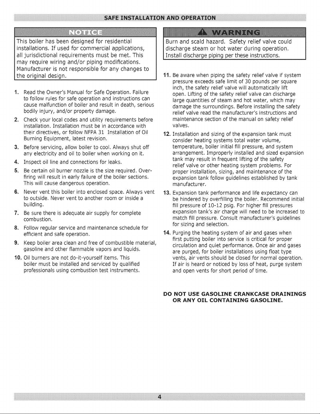
This boiler has been designed for residential
installations. Tf used for commercial applications,
all jurisdictional requirements must be met. This
may require wiring and/or piping modifications.
Manufacturer is not responsible for any changes to
the original design.
1, Read the Owner's Manual for Safe Operation. Failure
to follow rules for safe operation and instructions can
cause malfunction of boiler and result in death, serious
bodily injury, and/or property damage.
2, Check your local codes and utility requirements before
installation. Installation must be in accordance with
their directives, or follow NFPA 31 Installation of Oil
Burning Equipment, latest revision.
3, Before servicing, allow boiler to cool. Always shut off
any electricity and oil to boiler when working on it,
4, Inspect oil line and connections for leaks.
5, Be certain oil burner nozzle is the size required. Over-
firing will result in early failure of the boiler sections.
This will cause dangerous operation.
6, Never vent this boiler into enclosed space. Always vent
to outside. Never vent to another room or inside a
building.
7, Be sure there is adequate air supply for complete
combustion.
8. Follow regular service and maintenance schedule for
efficient and safe operation.
9. Keep boiler area clean and free of combustible material,
gasoline and other flammable vapors and liquids.
10. Oil burners are not do-it-yourself items. This
boiler must be installed and serviced by qualified
professionals using combustion test instruments,
Burn and scald hazard. Safety relief valve could
discharge steam or hot water during operation.
Tnstall discharge piping per these instructions.
11.
Be aware when piping the safety relief valve if system
pressure exceeds safe limit of 30 pounds per square
inch, the safety relief valve will automatically lift
open. Lifting of the safety relief valve can discharge
large quantities of steam and hot water, which may
damage the surroundings. Before installing the safety
relief valve read the manufacturer's instructions and
maintenance section of the manual on safety relief
valves.
12.
Installation and sizing of the expansion tank must
consider heating systems total water volume,
temperature, boiler initial fill pressure, and system
arrangement. Improperly installed and sized expansion
tank may result in frequent lifting of the safety
relief valve or other heating system problems. For
proper installation, sizing, and maintenance of the
expansion tank follow guidelines established by tank
manufacturer.
13. Expansion tank performance and life expectancy can
be hindered by overfilling the boiler. Recommend initial
fill pressure of 10-12 psig. For higher fill pressures
expansion tank's air charge will need to be increased to
match fill pressure. Consult manufacturer's guidelines
for sizing and selection.
14. Purging the heating system of air and gases when
first putting boiler into service is critical for proper
circulation and quiet performance. Once air and gases
are purged, for boiler installations using float type
vents, air vents should be closed for normal operation.
If air is heard or noticed by loss of heat, purge system
and open vents for short period of time.
DO NOT USE GASOLINE CRANKCASE DRJ_ININGS
OR ANY OIL CONTAINING GASOLINE,
iiiiiiiiiiiiiiiiiiiiiiiiiiiiiiiiiiiiiiiiiiiiiiiiiiiiiiiiiiiiiiiiiiiiiiiiiiiiiiiiiiiiiiiiiiiiiiiiiiiiiiiiiiiiiiiiiiiiiiiiiiiiiiiiiiiiiiiiiiiiiiiiiiiiiiiiiiiiiiiiiiiiiiiiiiiiiiiiiiiiiiiiiiiiiiiiiiiiiiiiiiiiiiiiiiiiiiiiiiiiiiiiiiiiiiiiiiiiiiiiiiiiiiiiiiiiiiiiiiiiiiiiiiiiiiiiiiiiiiiiiiiiiiiiiiiiiiiiiiiLi:i!6!i_ i_i_!!_iii!_!!i!!i!!i!!i!!i!!i_i!i_ii¸i:¸i_iiiiiiiiiiiiii_ii!i_ii6i!i_!:i:_ii_i_ii_i_i:_i:_i:_i:_i:_i:_i:_i:_i:_i:_i:_i:_i:_i:_i:_i:_i:_i:_i:_i:_i:_i:_i:_i:_i:_i:_i:_i:_i:_i:_i:_i:_i:_i:_i:_i:_i:_i:_i:_i:_i:_i:_i:_i:_i:_i:_i:_i:_i:_i:_i:_i:_i:_i:_i:_i:_i:_i:_i:_i:_i:_i:_i:_i:_i:_i:_i:_i:_i:_i:_i:_i:_i:_i:_i:_i:_i:_i:_i:_i:_i:_i:_i:_i:_i:_i:_i:_i:_i:_i:_i:_i:_i:_i:_i:_i:_i:_i:_i:_i:_i:_i:_i:_i:_i:_i:_i:_i:_i:_i:_i:_i:_i:_i:_i:_i:_i:_i:_i:_i:_i:_i:_i:_i:_i:_i:_i:_i:_i:_i:_i:_i:_i:_i:_i:_i:_i:_i:_i:_i:_i:_i:_i:_i:_i:_i:_i:_i:_i:_i:_i:_i:_i:_i:_i:_i:_i:_i:_i:_i:_i:_i:_i:_i:_i:_i:_i:_i:_i:_i:_i:_i:_i:_i:_i:_i:_i:_i:_i:_i:_i:_i:_i:_i:_i:_i:_i:_i:_i:_i:_i:_i:_i:_i:_i:_i:_i:_i:_i:_i:_i:_i:_i:_i:_i:_i:_i:_i:_i:_i:_i:_i:_i:_i:_i:_i:_i:_i:_i:_i:_i:_i:_i:_i:_i:_i:_i:_i:_i:_i:_i:_i:_i:_i:_i:_i:_i:_i:_i:_i:_i:_i:_i:_i:_i:_i:_i:_i:_i:_i:_i:_i:_i:_i:_i:_i:_i:_i:_i:_i:_i:_i:_i:_i:_i:_i:_i:_i:_i:_i:_i:_i:_i:_i:_i:_i:_i:_i:_i:_i:_i:_i:_i:_i:_i:_i:_i:_i:_i:_i:_i:_i:_i:_i:_i:_i:_i:il
Complete Prior To Installing Boiler.
A.
Verify you have selected the right size boiler with
proper capacity. AHRI rating of boiler selected 2.
should be greater than or equal to calculated peak
heating load (heat loss) for building or area(s)
served by boiler and associated hot water heating 3.
systems. See boiler rating and capacity table
previously listed in this manual. Any heat loss
calculations used should be based on approved
methods.
B. Boiler must be supplied with proper oil supply
and oil piping, sufficient fresh combustion air, and
suitable electrical supply.
C. Boiler must be connected to suitable venting system
and piping system adequate to distribute heating
load.
D. Properly locate and install thermostat for heating
system control.
Any doubts as to requirements, check with local authorities
and obtain professional help where needed. OPERATING
INSTRUCTIONS, FINAL CHECKS AND ADJUSTMENTS, and
MAINTENANCE sections in this manual are vital to the
proper and safe operation of the heating system.
1,
Place boiler in location centralized with the piping
system and as close to chimney as possible.
Boiler must be level. If necessary use metal shims
beneath boiler's feet,
Use raised base if floor can become wet or damp.
4,
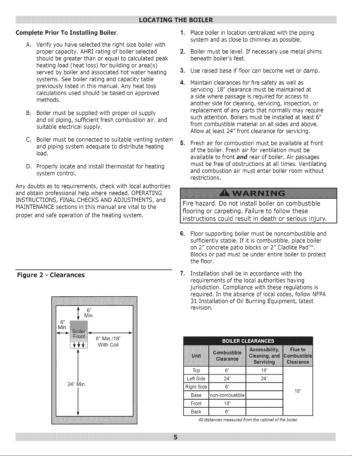
Maintain clearances for fire safety as well as
servicing. 18" clearance must be maintained at
a side where passage is required for access to
another side for cleaning, servicing, inspection, or
replacement of any parts that normally may require
such attention. Boilers must be installed at least 6"
from combustible material on all sides and above.
Allow at least 24" front clearance for servicing.
,
Fresh air for combustion must be available at front
of the boiler. Fresh air for ventilation must be
available to front and rear of boiler. Air passages
must be free of obstructions at all times. Ventilating
and combustion air must enter boiler room without
restrictions.
Fire hazard. Do not install boiler on combustible
flooring or carpeting. Failure to follow these
instructions could result in death or serious injury.
Figure 2 = Clearances
24" Min.
6" Min./l 8"
With Coil
,
Floor supporting boiler must be noncombustible and
sufficiently stable. If it is combustible, place boiler
on 2" concrete patio blocks or 2" Cladlite PadT",
Blocks or pad must be under entire boiler to protect
the floor.
, Installation shall be in accordance with the
requirements of the local authorities having
jurisdiction. Compliance with these regulations is
required. In the absence of local codes, follow NFPA
31 Installation of Oil Burning Equipment, latest
revision.
Top
Left Side
Right Side
Base
Front
Back
All distances measured from the cabinet of the boiler.
6 _
24"
non-combustible
18"
6"
18 _
24"
18 _
MIN. 2" I.D.
VENT PIPE
OVERCURRENT
PROTECTED
SAFETY SWITCH
2" FILL
PIPE
ENTRANq
SWITCH
LINESTO
APPLIANCES
SERVICE LINE
ELECTRIC LINE
FILL VALVE
AND SHUTOFF
DIAPHRAGM
EXPANSION TANK
REGULATOR
VENT
PIPE
DRAFT
"11
m_
c
w
I
SHUT OFF
VALVE
OIL FILTER
OIL LINES J
OILTANK
TO OUTSIDE
TO RADIATION
OIL BURNER
FOUNDATIONS
RELIEFVALVE
CIRCULATING
PUMP IN
RETURN LINE
OR AFTER THE
EXPANSION
TANK
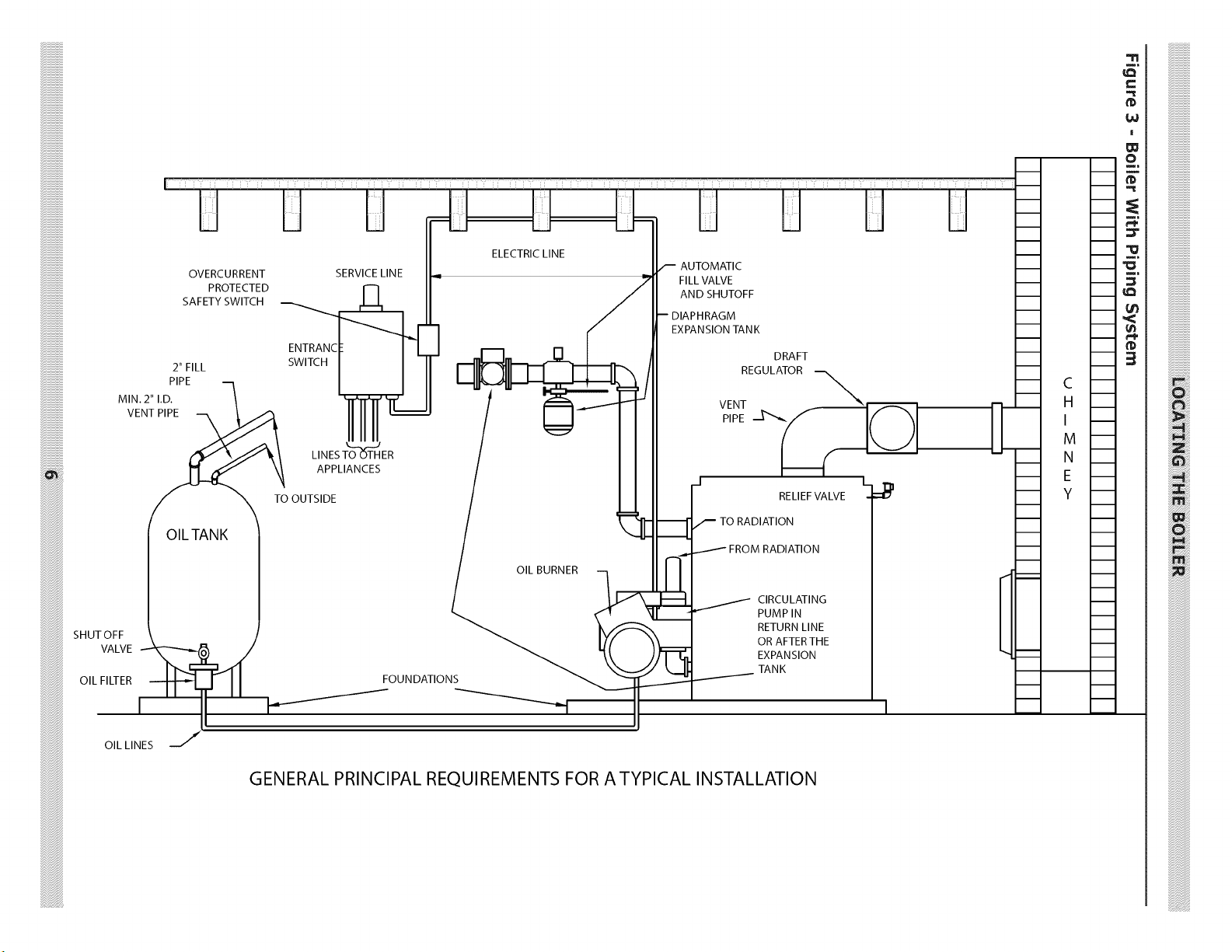
GENERAL PRINCIPAL REQUIREMENTS FOR A TYPICAL INSTALLATION
EXAMPLE 2: Boiler Located in Confined Space
Asphyxiation, fire hazard. Do not obstruct air
openings to combustion area. Follow instructions
below, to maintain adequate combustion air.
Install outside air intake if you use fireplace or
kitchen or bathroom exhaust fan. These devices rob
boiler and water heater of combustion air.
Provide enough fresh air to assure proper combustion.
Fire in the boiler uses oxygen. It must have continuous
supply. Air in the house contains only enough oxygen to
supply burner for short time. Outside air must enter the
house to replace air used by the burner, Study the following
examples 1 and 2 to determine your fresh air requirements.
EXAMPLE 1: Boiler Located in Unconfined Space
If your boiler is in an open area (un-partitioned basement)
in conventional house, air that leaks through cracks around
doors and windows will usually be adequate to provide air
for combustion. Doors should not fit tightly. Do not caulk
cracks around windows.
An unconfined space is defined as space whose volume is
not less than 50 cubic feet per 1,000 Btu per hour of total
input rating of all appliances installed in that space.
A, All Air from Inside the Building: Confined
space shall be provided with two permanent openings
communicating directly with additional room(s) of sufficient
volume so the combined volume of all spaces meets the
criteria for unconfined space. Total input of all combustion
equipment installed in combined space shall be considered
in making this determination. Each opening shall have
minimum free area of one square inch per 1,000 Btu per
hour of total input rating of all combustion equipment in the
confined space, but not less than 100 square inches. One
opening shall be within 12 inches of top and one within 12
inches of bottom of the enclosure.
Example: Your boiler is rated at 100,000 Btu per hour,
Water heater is rated at 30,000 Btu per hour, Total is
130,000 Btu per hour, You need two grilles, each with 130
square inches of FREEopening. Metal grilles have about
60% FREEopening. To find Iouvered area needed, multiply
free opening required by 1.7 (130 x 1.7 = 221.0 sq. in.
Iouvered area). In this example, two grilles each having 8"
x 30" (240 sq. in.) Iouvered area would be used.
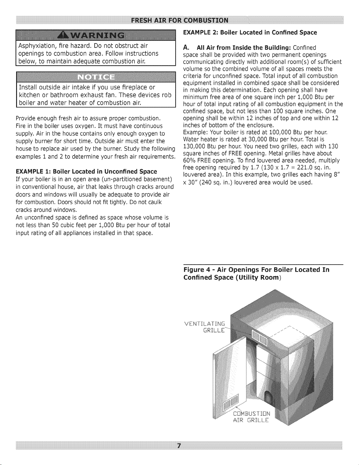
Figure 4 - Air Openings For Boiler Located In
Confined Space (Utility Room)
VENTILATING
B,
All Air from Outdoors: Confined space shall
be provided with two permanent openings, one
commencing within 12 inches of top and commencing
within 12 inches of bottom of enclosure. Openings
shall communicate directly, or by ducts, with outdoors
or spaces (crawl or attic) that freely communicate with
outdoors.
1. When directly communicating with outdoors, each
opening shall have minimum free area of one
3. When communicating with outdoors through
horizontal ducts, each opening shall have
minimum free area of one square inch per 2,000
Btu per hour of total input rating of all equipment
in the enclosure.
4. When ducts are used, they shall be of same cross
sectional area as free area of openings to which
they connect. Minimum dimension of rectangular
air ducts shall be not less than three inches.
square inch per 4,000 Btu per hour of total input
rating of all equipment in the enclosure.
2. When communicating with outdoors through
vertical ducts, each opening shall have minimum
free area of one square inch per 4,000 Btu per
hour of total input rating of all equipment in the
enclosure.
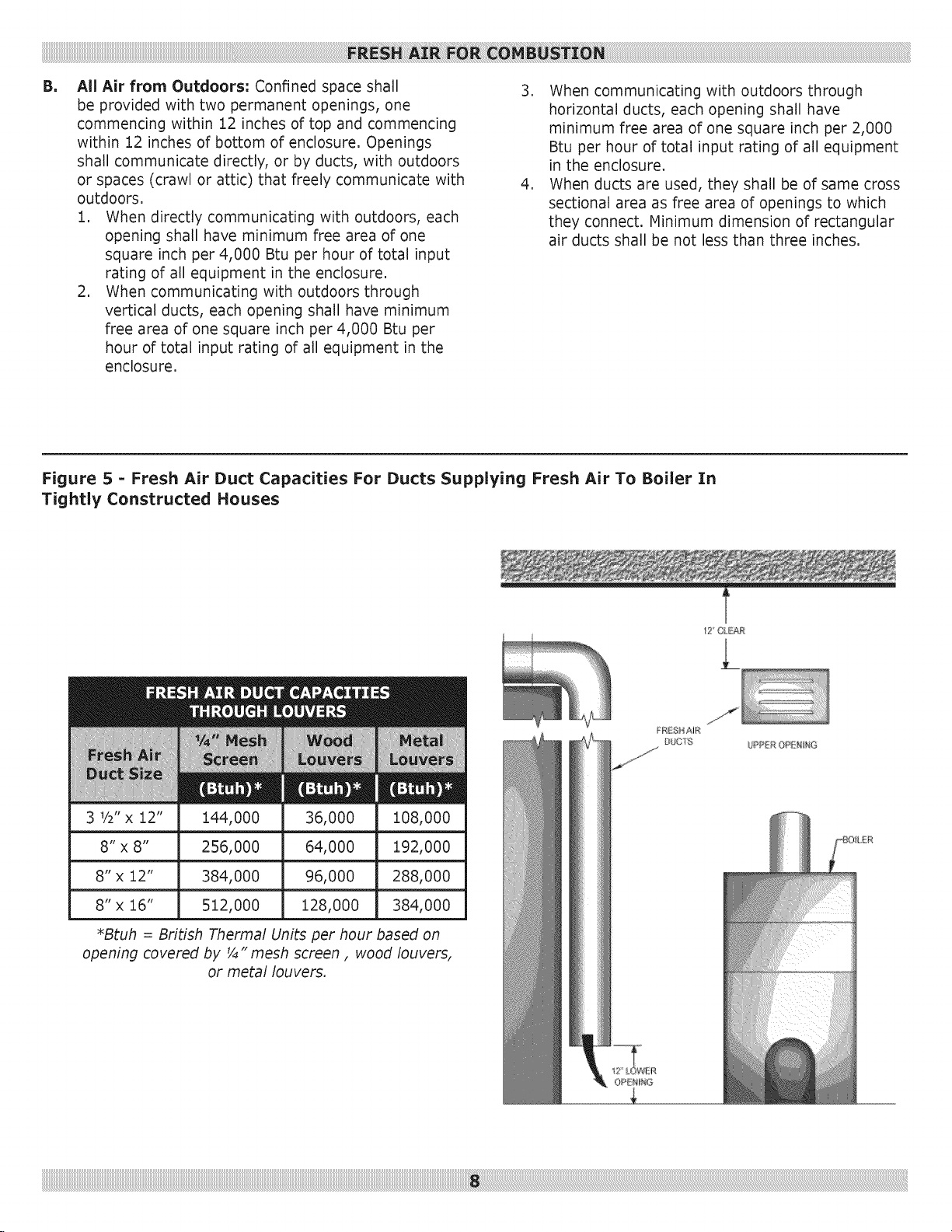
Figure 5 = Fresh Air Duct Capacities For Ducts Supplying Fresh Air To Boiler In
Tightly Constructed Houses
3 V2"x 12" 144,000 36,000 i08,000
8" x 8" 256,000 64,000 192,000
8" x 12" 384,000 96,000 288,000
8" x 16" 512,000 128,000 384,000
*Btuh = British Thermal Units per hour based on
opening covered by _" mesh screen, wood louvers,
or metal louvers.
12" CL£A£
,
Installation of boiler for new heating system,
Install all of radiation units (panels, radiators,
baseboard, or tubing) and supply and return mains
first. After all heating system piping and components
have been installed, make final connection of system
piping to boiler. It is recommended to mount circulating
pump on supply side piping, such that it pumps away
from expansion tank. Refer to figures on next pages.
,
Equip hot water boiler installed above radiation
level with low water cut off device. Periodic inspection
is necessary, as is flushing of float type devices, per
low water cut off manufacturer's specific instructions.
,
Packaged boiler is set up with 1¼" NPT supply
and return piping from front of boiler. Boiler supply
and return piping can be moved to rear of boiler. Boiler
should not be piped return line to front, supply line
to rear, or vice versa, will cause boiler water to short
circuit heat exchanger. Piping connections may require
additional fittings and parts.
,
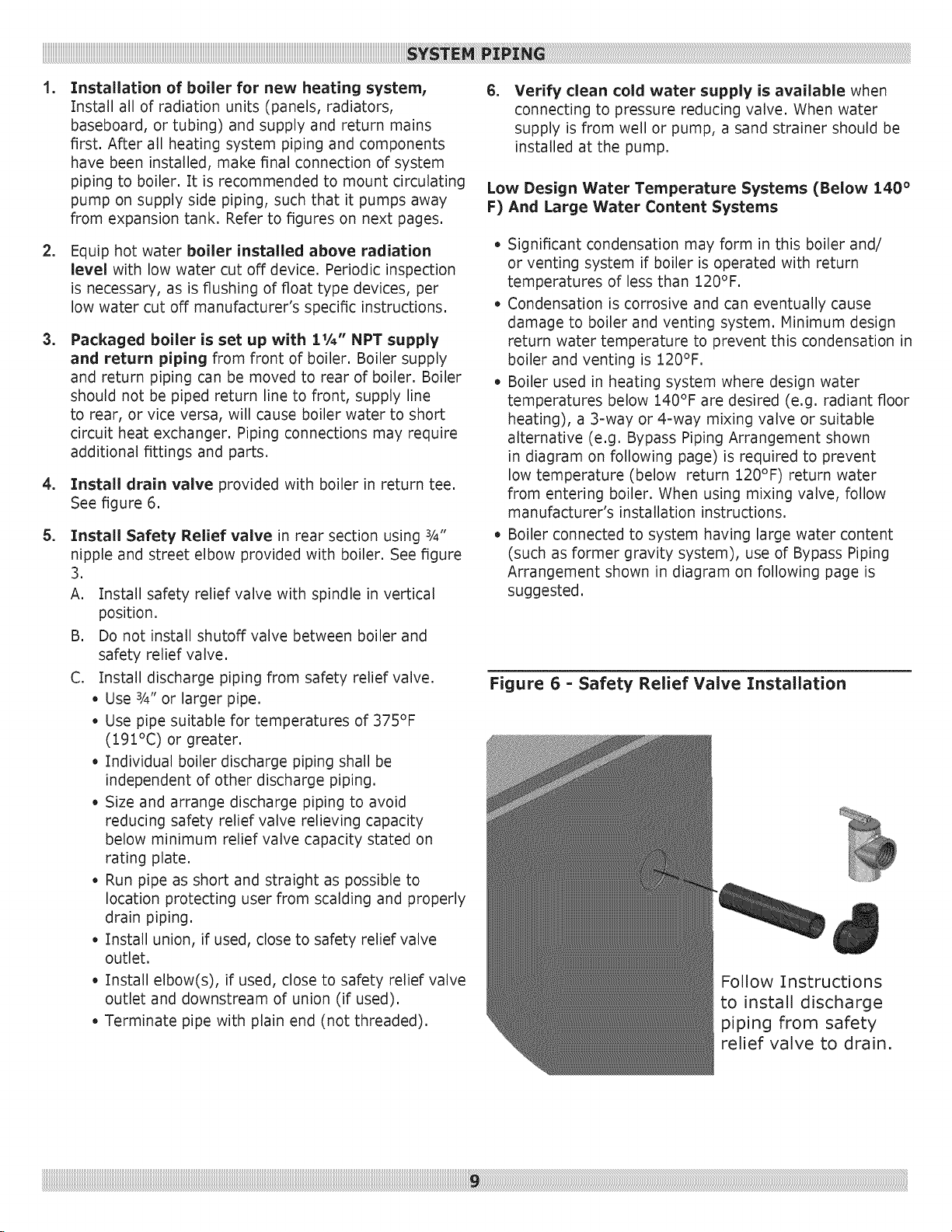
Install drain valve provided with boiler in return tee.
See figure 6.
,
Install Safety Relief valve in rear section using ¾"
nipple and street elbow provided with boiler. See figure
3.
A. Install safety relief valve with spindle in vertical
position.
B. Do not install shutoff valve between boiler and
safety relief valve.
C. Install discharge piping from safety relief valve.
• Use 3/4"or larger pipe.
• Use pipe suitable for temperatures of 375°F
(191°C) or greater.
• Individual boiler discharge piping shall be
independent of other discharge piping.
• Size and arrange discharge piping to avoid
reducing safety relief valve relieving capacity
below minimum relief valve capacity stated on
rating plate.
• Run pipe as short and straight as possible to
location protecting user from scalding and properly
drain piping.
• Install union, if used, close to safety relief valve
outlet.
• Install elbow(s), if used, close to safety relief valve
outlet and downstream of union (if used).
• Terminate pipe with plain end (not threaded).
,
Verify clean cold water supply is available when
connecting to pressure reducing valve. When water
supply is from well or pump, a sand strainer should be
installed at the pump.
Low Design Water Temperature Systems (Below 140 °
F) And Large Water Content Systems
• Significant condensation may form in this boiler and/
or venting system if boiler is operated with return
temperatures of less than 120°F.
• Condensation is corrosive and can eventually cause
damage to boiler and venting system. Minimum design
return water temperature to prevent this condensation in
boiler and venting is 120°F.
• Boiler used in heating system where design water
temperatures below 140°F are desired (e.g. radiant floor
heating), a 3=way or 4=way mixing valve or suitable
alternative (e.g. Bypass Piping Arrangement shown
in diagram on following page) is required to prevent
low temperature (below return 120°F) return water
from entering boiler. When using mixing valve, follow
manufacturer's installation instructions.
• Boiler connected to system having large water content
(such as former gravity system), use of Bypass Piping
Arrangement shown in diagram on following page is
suggested.
Figure 6 = Safety Relief Valve Installation
Follow Instructions
to install discharge
piping from safety
relief valve to drain.
iiiiiiiiiiiiiiiiiiiiiiiiiiiiiiiiiiiiiiiiiiiiiiiiiiiiiiiiiiiiiiiiiiiiiiiiiiiiiiiiiiiiiiiiiiiiiiiiiiiiiiiiiiiiiiiiiiiiiiiiiiiiiiiiiiiiiiiiiiiiiiiiiiiiiiiiiiiiiiiiiiiiiiiiiiiiiiiiiiiiiiiiiiiiiiiiiiiiiiiiiiiiiiiiiiiiiiiiiiiiiiiiiiiiiiiiiiiiiiiiiiiiiiiiiiiiiiiiiiiiiiiiiiiiiiiiiiiiiiiiiiiiiiiiiiiiiiiiiiiiiiiiiiiiiiiiiiiiiiiiiiiiiiiiiiiiiiiiiiiiiiiiiiiiiiiiiiiiiiiiiiiiiiiiiiiiiiiiiiiiiiiiiiiiiiiiiiiiiiiiiiiiiiiiiiiiiiiiiiiiiiiiiiiiiiiiiiiiiiiiiiiiiiiiiiiiiiiiiiiiiiiiiiiiiiiiiiiiiiiiiiiiiiiiiiiiiiiiiiiiiiiiiiiiiiiiiiiiiiiiiiiiiiiiiiiiiiiiiiiiiiiiiiiiiiiiiiiiiiiiiiiiiiiiiiiiiiiiiiiiiiiiiiiiiiiiiiiiiiiiiiiiiiiiiiiiiiiiiiiiiiiiiiiiiiiiiiiiiiiiiiiiiiiiiiiiiiiiiiiiiiiiiiiiiiiiiiiiiiiiiiiiiiiiiiiiiiiiiiiiiiiiiiiiiiiiiiiiiiiiiiiiiiiiiiiiiiiiiiiiiiiiiiiiiiiiiiiiiiiiiii_!!i!!i!!i!!i!!i!!i!!i!!i!!i!!i!!i!!i!!i!!i!!i!!i!!i!!i!!i!!i!!i!!i!!i!!i!!i!!i!!i!!i!!i!!i!!i!!i!!i!!i!!i!!i!!i!!i!!i!!i!!i!!i!!i!!i!!i!!i!!i!!i!!i!!i!!i!!i!!i!!i!!i!!i!!i!!i!!i!!i!!i!!i!!i!!i!!i!!i!!i!!i!!i!!i!!i!!i!!i!!i!!i!!i!!i!!i!!i!!i!!i!!i!!i!!i!!i!!i!!i!!i!!i!!i!!i!!i!!i!!i!!i!!i!!i!!i!!i!!i!!i!!i!!i!!i!!i!!i!!i!!i!!i!!i!!i!!i!!i!!i!!i!!i!!i!!i!!i!!i!!i!!i!!i!!i!!i!!i!!i!!i!!i!!i!!i!!i!!i!!i!!i!!i!!i!!i!!i!!i!!i!!i!!i!!i!!i!!i!!i!!i!!i!!i!!i!!i!!i!!i!!i!!i!!i!!i!!i!!i!!i!!i!!i!!i!!i!!i!!i!!i!!i!!i!!i!!i!!i!!i!!i!!i!!i!!i!!i!!i!!i!!i!!i!!i!!i!!i!!i!!i!!i!!i!!i!!i!!i!!i!!i!!i!!i!!i!!i!!i!!i!!i!!i!!i!!i!!i!!i!!i!!i!!i!!i!!i!!i!!i!!i!!i!!i!!i!!i!!i!!i!!i!!i!!i!!i!!i!!i!!i!!i!!i!!i!!i!!i!!i!!i!!i!!i!!i!!i!!i!!i!!i!!i!!i!!i!!i!!i!!i!!i!!i!!i!!i!!i!!i!!i!!i!!i!!i!!i!!i!!i!!i!!i!!i!!i!!i!!i!!i!!i!!i!!i!!i!!i!!i!!i!!i!!i!!i!!i!!i!!i!!i!!i!!i!!i!!i!!i!!i!!i!!i!!i!!i!!i!!i!!i!!i!!i!!i!!i!!i!!i!!i!!i!!i!!i!!i!!i!!i!!i!!i!!i!!i!!i!!i!!i!!i!!i!!i!!i!!i!!i!!i!!i!!i!!i!!i!!i!!i!!i!!i!!i!!i!!i!!i!!i!!i!!i!!i!!i!!i!!i!!i!!i!!i!!i!!i!!i!!i!!i!!i!!i!!i!!i!!i!!i!!i!!i!!i!!i!!i!!i!!i!!i!!i!!i!!i!!i!!i!!i!!i!!i!!i!!i!!i!!i_ii!ii!il!_!!i!
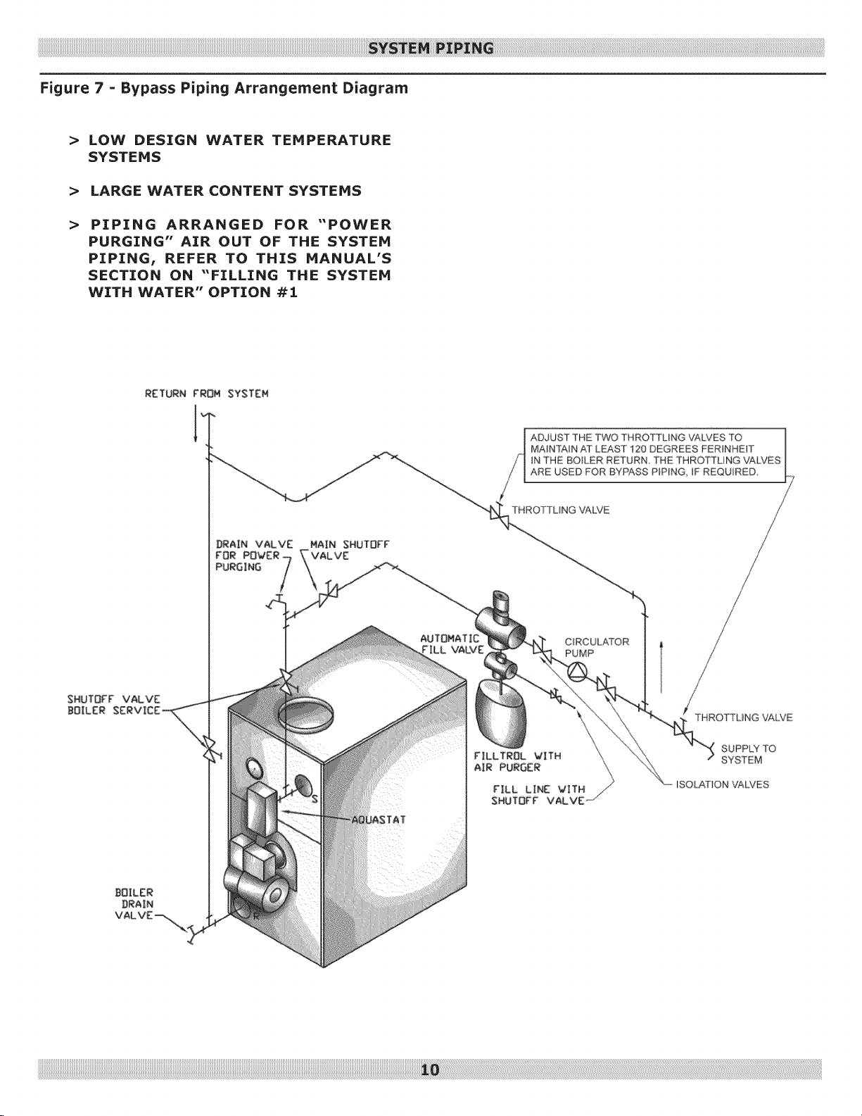
Figure 7 = Bypass Piping Arrangement Diagram
> LOW DESIGN WATER TEMPERATURE
SYSTEMS
> LARGE WATER CONTENT SYSTEMS
> PIPING ARRANGED FOR "POWER
PURGING" AIR OUT OF THE SYSTEM
PIPING! REFER TO THIS MANUAL'S
SECTION ON "FILLING THE SYSTEM
WITH WATER" OPTION #i
SHUTOFF VALVE
BOILER
AUTOMATIC
rILL VALVE
ADJUST THE TWO THROTTLING VALVES TO |
MAINTAIN AT LEAST 120 DEGREES FER_NHE_T
iN THE BOH_ER RETURN THE THROTTUNG VALP_ES
ARE USED FOR BYPASS PIPING, IF REQUIRED
THROTTLING VALVE
FILLTROL VITH
AIR PURGER
|
1
CIRCULATOR
PUMP
THROTTUNG VALVE
SUPPLY TO
SYSTEM
ISOL,AS_ON VALVES
 Loading...