

Page 1
Hodels
SERIES
3EW,65
3EW,75
3EWI,O0
4EW,90
4EW1,25
4EW1,50
SEW1,20
5EW1,75
OIL-FIRED CAST IRON
HOT WATER
INSTALLATION, OPERATION
& HAINTENANCE HANUAL
,?__,_g_,',,_& .......................................................
_!._,_,, ,
_',!_,._;_#_ ::::::::::::::::::::::::::::::.............
_i:_'_,_;_! ..........................................
_._,_.',_rL_
,
dS
Maximum Allowable
Working Pressure 50 psi.
Manufactured by:
ECR international, inc.
220! DwyerAwnue. Utica NY 13501
web s_te www ecnnternat/onal corn
H
P/N# 240009549, Rev B [10/2012]
Page 2
Safety Notices .............................................. 2
Boiler Ratings And Capacities ......................... 3
Fresh Air For Combustion ............................... 7
System Piping .............................................. 9
Chimney And Chimney Connections .............. 16
Typical Chimney Connection ......................... 17
Electrical Connections ................................. 18
Filling The Boiler ....................................... 19
Operating The Boiler ................................. 20
Checking And Adjusting Controls .................. 23
Maintenance .............................................. 24
Oil Boiler Cleaning Instructions .................... 25
Oil Burner Cleaning ..................................... 26
Service Hints ............................................. 27
Electrical Wiring ......................................... 28
Equipment And Optional Accessories ............. 29
Introduction
Empire Water boiler is a natural draft oil fired hot water
boiler comprised of cast iron sections. Empire Water
boiler is available with 3, 4, or 5 cast iron sections. These
sections are held together by cast iron push nipples.
Empire Water boiler is capable of firing #2 fuel oil from
0.65 gph up to 2.00 gph. All packaged boilers include a
swing door, Honeywell limit, temperature and pressure
gauge, safety relief valve, drain valve, flue brush, and extra
boiler tap for expansion tank or air elimination.
Boiler installation shall be completed by qualified agency.
Become familiar with symbols identifying
potential hazards.
This is the safety alert symbol. Symbol alerts you
to potential personal injury hazards. Obey all safety
messages following this symbol to avoid possible injury or
death.
Indicates a hazardous situation which, if not avoided,
WILL result in death or serious injury
Indicates a hazardous situation which, if not avoided,
could result in death or serious injury.
CAUTION
Indicates a hazardous situation which, if not avoided,
could result in minor or moderate injury.
Used to address practices not related to personal
injury.
iiiiiiiiiiiiiiiiiiiiiiiiiiiiiiiiiiiiiiiiiiiiiiiiiiiiiiiiiiiiiiiiiiiiiiiiiiiiiiiiiiiiiiiiiiiiiiiiiiiiiiiiiiiiiiiiiiiiiiiiiiiiiiiiiiiiiiiiiiiiiiiiiiiiiiiiiiiiiiiiiiiiiiiiiiiiiiiiiiiiiiiiiiiiiiiiiiiiiiiiiiiiiiiiiiiiiiiiiiiiiiiiiiiiiiiiiiiiiiiiiiiiiiiiiiiiiiiiiiiiiiiiiiiiiiiiiiiiiiiiiiiiiiiiiiiiiiiiiiiiiiiiiiiiiiiiiiiiiiiiiiiiiiiiiiiiiiiiiiiiiiiiiiiiiiiiiiiiiiiiiiiiiiiiiiiiiiiiiiiiiiiiiiiiiiiiiiiiiiiiiiiiiiiiiiiiiiiiiiiiiiiiiiiiiiiiiiiiiiiiiiiiiiiiiiiiiiiiiiiiiiiiiiiiiiiiiiiiiiiiiiiiiiiiiiiiiiiiiiiiiiiiiiiiiiiiiiiiiiiiiiiiiiiiiiiiiiiiiiiiiiiiiiiiiiiiiiiiiiiiiiiiiiiiiiiiiiiiiiiiiiiiiiiiiiiiiiiiiiiiiiiiiiiiiiiiiiiiiiiiiiiiiiiiiiiiiiiiiiiiiiiiiiiiiiiiiiiiiiiiiiiiiiiiiiiiiiiiiiiiiiiiiiiiiiiiiiiiiiiiiiiiiiiiiiiiiiiiiiiiiiiiiiiiiiiiiiiiiiiiiiiiiiiiiiiiiiiiiiiiii!!!_i;ii;ii;ii;ii;ii;ii;ii;ii;ii;ii;ii;ii;ii;ii;ii;ii;ii;ii;ii;ii;ii;ii;ii;ii;ii;ii;ii;ii;ii;ii;ii;ii;ii;ii;ii;ii;ii;ii;ii;ii;ii;ii;ii;ii;ii;ii;ii;ii;ii;ii;ii;ii;ii;ii;ii;ii;ii;ii;ii;ii;ii;ii;ii;ii;ii;ii;ii;ii;ii;ii;ii;ii;ii;ii;ii;ii;ii;ii;ii;ii;ii;ii;ii;ii;ii;ii;ii;ii;ii;ii;ii;ii;ii;ii;ii;ii;ii;ii;ii;ii;ii;ii;ii;ii;ii;ii;ii;ii;ii;ii;ii;ii;ii;ii;ii;ii;ii;ii;ii;ii;ii;ii;ii;ii;ii;ii;ii;ii;ii;ii;ii;ii;ii;ii;ii;ii;ii;ii;ii;ii;ii;ii;ii;ii;ii;ii;ii;ii;ii;ii;ii;ii;ii;ii;ii;ii;ii;ii;ii;ii;ii;ii;ii;ii;ii;ii;ii;ii;ii;ii;ii;ii;ii;ii;ii;ii;ii;ii;ii;ii;ii;ii;ii;ii;ii;ii;ii;ii;ii;ii;ii;ii;ii;ii;ii;ii;ii;ii;ii;ii;ii;ii;ii;ii;ii;ii;ii;ii;ii;ii;ii;ii;ii;ii;ii;ii;ii;ii;ii;ii;ii;ii;ii;ii;ii;ii;ii;ii;ii;ii;ii;ii;ii;ii;ii;ii;ii;ii;ii;ii;ii;ii;ii;ii;ii;ii;ii;ii;ii;ii;ii;ii;ii;ii;ii;ii;ii;ii;ii;ii;ii;ii;ii;ii;ii;ii;ii;ii;ii;ii;ii;ii;ii;ii;ii;ii;ii;ii;ii;ii;ii;ii;ii;ii;ii;ii;ii;ii;ii;ii;ii;ii;ii;ii;ii;ii;ii;ii;ii;ii;ii;ii;ii;ii;ii;ii;ii;ii;ii;ii;ii;ii;ii;ii;ii;ii;ii;ii;ii;ii;ii;ii;ii;ii;ii;ii;ii;ii;ii;ii;ii;ii;ii;ii;ii;ii;ii;ii;ii;ii;ii;ii;ii;ii;ii;ii;ii;ii;ii;ii;ii;ii;ii;ii;ii;ii;ii;ii;ii;ii;ii;ii;ii;ii;ii;ii;ii;ii;ii;ii;ii;ii;ii;ii;ii;ii;ii;ii;ii;ii;_i_!
Page 3
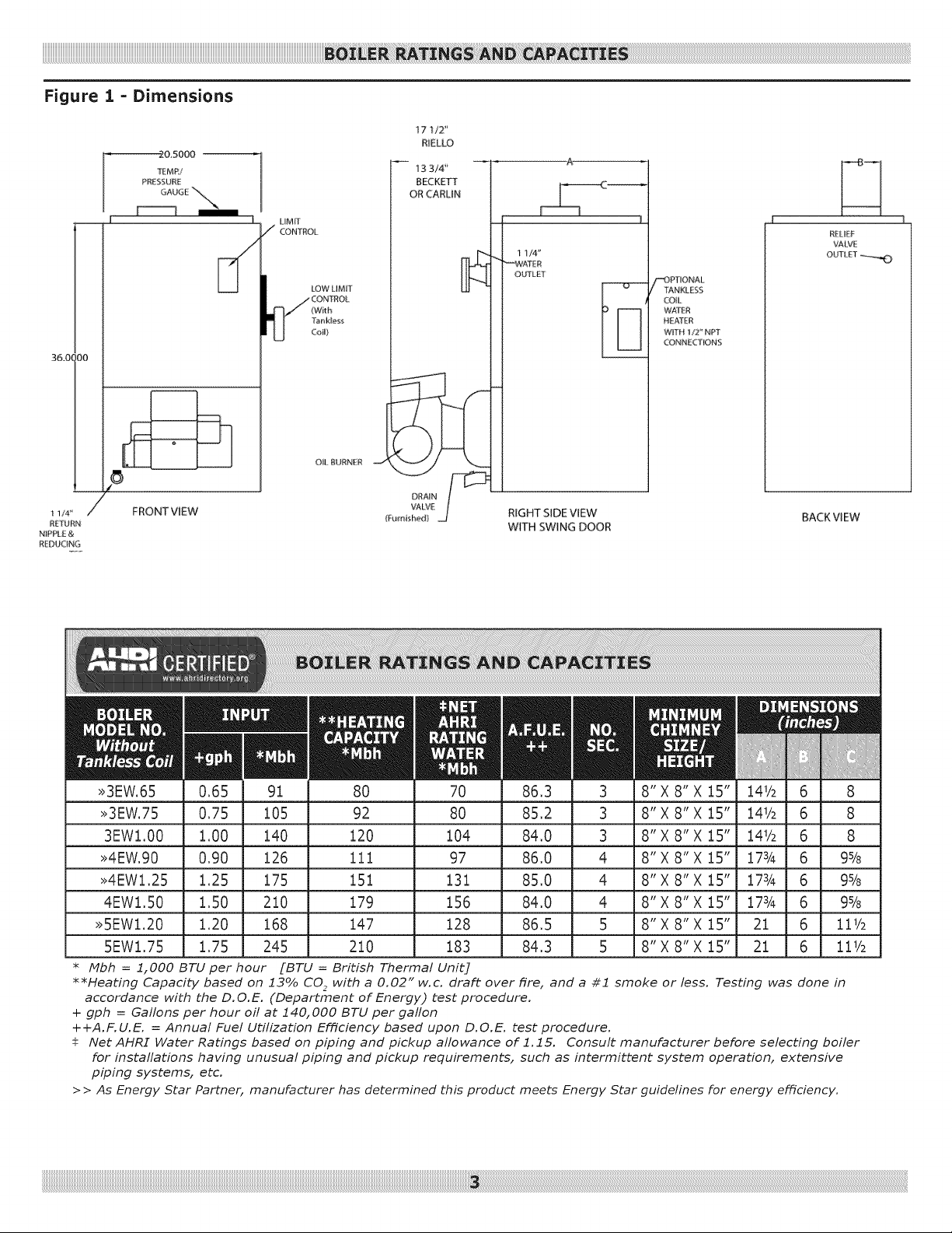
Figure 1 = Dimensions
2&5000 --
TEMR/
PRESSUiqE
GAUGE "_'_
36.01 iO0
I
LIMIT
/ CONTROL
I_/CO NTROL
LOW LIMIT
(With
Tank_ess
CoiU}
O&BURNER
17 1/2"
RIELLO
13 3/4'
BECKETT
OR CARLiN
1 1/4"
_,#,,#ATER
OUTLET
"_)PTIONA L
I"ANKLESS
COIL
WAT£R
HEATER
WITH 1/2" NPT
CONNE£T_ONS
RELIEF
VALVE
OUTLET_
DRAIN
VALVE
(Furnished)
RIGHT SIDE VIEW
WITH SWING DOOR
8" X 8" X 15"
8" X 8" X 15"
8" X 8" X 15"
8" X 8" X 15"
8" X 8" X 15"
8" X 8" X 15"
8" X 8" X 15"
8" X 8" X 15"
I 1/4 '_
REIURN
N_PP_ E &
REDUCING
/_' FRONT VIEW
>>3EW.65 80 70 86,3
>>3EW.75 92 80 85,2
3EW1.00 120 104 84,0
>>4EW.90 111 97 86,0
>>4EWl,25 151 131 85,0
4EWl.50 179 156 84,0
>>5EWl.20 147 128 86,5
5EWl.75 210 183 84,3
* Mbh = 1,000 BTU per hour [BTU = BHtish Thermal Unit]
**Heating Capacity based on 13% CO2 with a 0.02" w.c. draft over fire, and a #1 smoke
or less. Testing was done in
accordance with the D.O.E. (Department of Energy) test procedure.
+ gph = Gallons per hour off at 140,000 BTU per gaflon
++A.F.U.E. = Annual Fuel Utilization Efficiency based upon D.O.E. test procedure.
Net AHRI Water Ratings based on piping and pickup allowance of 1.15. Consult manufacturer before selecting boiler
for instaflations having unusual piping and pickup requirements, such as intermittent system operation, extensive
piping systems, etc.
> > As Energy 5tar Partner, manufacturer has determined this product meets Energy 5tar guidelines for energy efficiency.
BACKVIEW
Page 4
This boiler has been designed for residential
installations. Tf used for commercial applications,
all jurisdictional requirements must be met. This
may require wiring and/or piping modifications.
Manufacturer is not responsible for any changes to
the original design.
1, Read the Owner's Manual for Safe Operation. Failure
to follow rules for safe operation and instructions can
cause malfunction of boiler and result in death, serious
bodily injury, and/or property damage.
2, Check your local codes and utility requirements before
installation. Installation must be in accordance with
their directives, or follow NFPA 31 Installation of Oil
Burning Equipment, latest revision.
3, Before servicing, allow boiler to cool. Always shut off
any electricity and oil to boiler when working on it,
4, Inspect oil line and connections for leaks.
5, Be certain oil burner nozzle is the size required. Over-
firing will result in early failure of the boiler sections.
This will cause dangerous operation.
6, Never vent this boiler into enclosed space. Always vent
to outside. Never vent to another room or inside a
building.
7, Be sure there is adequate air supply for complete
combustion.
8. Follow regular service and maintenance schedule for
efficient and safe operation.
9. Keep boiler area clean and free of combustible material,
gasoline and other flammable vapors and liquids.
10. Oil burners are not do-it-yourself items. This
boiler must be installed and serviced by qualified
professionals using combustion test instruments,
Burn and scald hazard. Safety relief valve could
discharge steam or hot water during operation.
Tnstall discharge piping per these instructions.
11.
Be aware when piping the safety relief valve if system
pressure exceeds safe limit of 30 pounds per square
inch, the safety relief valve will automatically lift
open. Lifting of the safety relief valve can discharge
large quantities of steam and hot water, which may
damage the surroundings. Before installing the safety
relief valve read the manufacturer's instructions and
maintenance section of the manual on safety relief
valves.
12.
Installation and sizing of the expansion tank must
consider heating systems total water volume,
temperature, boiler initial fill pressure, and system
arrangement. Improperly installed and sized expansion
tank may result in frequent lifting of the safety
relief valve or other heating system problems. For
proper installation, sizing, and maintenance of the
expansion tank follow guidelines established by tank
manufacturer.
13. Expansion tank performance and life expectancy can
be hindered by overfilling the boiler. Recommend initial
fill pressure of 10-12 psig. For higher fill pressures
expansion tank's air charge will need to be increased to
match fill pressure. Consult manufacturer's guidelines
for sizing and selection.
14. Purging the heating system of air and gases when
first putting boiler into service is critical for proper
circulation and quiet performance. Once air and gases
are purged, for boiler installations using float type
vents, air vents should be closed for normal operation.
If air is heard or noticed by loss of heat, purge system
and open vents for short period of time.
DO NOT USE GASOLINE CRANKCASE DRJ_ININGS
OR ANY OIL CONTAINING GASOLINE,
Page 5
iiiiiiiiiiiiiiiiiiiiiiiiiiiiiiiiiiiiiiiiiiiiiiiiiiiiiiiiiiiiiiiiiiiiiiiiiiiiiiiiiiiiiiiiiiiiiiiiiiiiiiiiiiiiiiiiiiiiiiiiiiiiiiiiiiiiiiiiiiiiiiiiiiiiiiiiiiiiiiiiiiiiiiiiiiiiiiiiiiiiiiiiiiiiiiiiiiiiiiiiiiiiiiiiiiiiiiiiiiiiiiiiiiiiiiiiiiiiiiiiiiiiiiiiiiiiiiiiiiiiiiiiiiiiiiiiiiiiiiiiiiiiiiiiiiiiiiiiiiiLi:i!6!i_ i_i_!!_iii!_!!i!!i!!i!!i!!i!!i_i!i_ii¸i:¸i_iiiiiiiiiiiiii_ii!i_ii6i!i_!:i:_ii_i_ii_i_i:_i:_i:_i:_i:_i:_i:_i:_i:_i:_i:_i:_i:_i:_i:_i:_i:_i:_i:_i:_i:_i:_i:_i:_i:_i:_i:_i:_i:_i:_i:_i:_i:_i:_i:_i:_i:_i:_i:_i:_i:_i:_i:_i:_i:_i:_i:_i:_i:_i:_i:_i:_i:_i:_i:_i:_i:_i:_i:_i:_i:_i:_i:_i:_i:_i:_i:_i:_i:_i:_i:_i:_i:_i:_i:_i:_i:_i:_i:_i:_i:_i:_i:_i:_i:_i:_i:_i:_i:_i:_i:_i:_i:_i:_i:_i:_i:_i:_i:_i:_i:_i:_i:_i:_i:_i:_i:_i:_i:_i:_i:_i:_i:_i:_i:_i:_i:_i:_i:_i:_i:_i:_i:_i:_i:_i:_i:_i:_i:_i:_i:_i:_i:_i:_i:_i:_i:_i:_i:_i:_i:_i:_i:_i:_i:_i:_i:_i:_i:_i:_i:_i:_i:_i:_i:_i:_i:_i:_i:_i:_i:_i:_i:_i:_i:_i:_i:_i:_i:_i:_i:_i:_i:_i:_i:_i:_i:_i:_i:_i:_i:_i:_i:_i:_i:_i:_i:_i:_i:_i:_i:_i:_i:_i:_i:_i:_i:_i:_i:_i:_i:_i:_i:_i:_i:_i:_i:_i:_i:_i:_i:_i:_i:_i:_i:_i:_i:_i:_i:_i:_i:_i:_i:_i:_i:_i:_i:_i:_i:_i:_i:_i:_i:_i:_i:_i:_i:_i:_i:_i:_i:_i:_i:_i:_i:_i:_i:_i:_i:_i:_i:_i:_i:_i:_i:_i:_i:_i:_i:_i:_i:_i:_i:_i:_i:_i:_i:_i:_i:_i:_i:_i:_i:_i:_i:_i:_i:_i:_i:_i:_i:_i:_i:_i:_i:_i:_i:_i:_i:_i:_i:_i:_i:_i:_i:_i:_i:il
Complete Prior To Installing Boiler.
A.
Verify you have selected the right size boiler with
proper capacity. AHRI rating of boiler selected 2.
should be greater than or equal to calculated peak
heating load (heat loss) for building or area(s)
served by boiler and associated hot water heating 3.
systems. See boiler rating and capacity table
previously listed in this manual. Any heat loss
calculations used should be based on approved
methods.
B. Boiler must be supplied with proper oil supply
and oil piping, sufficient fresh combustion air, and
suitable electrical supply.
C. Boiler must be connected to suitable venting system
and piping system adequate to distribute heating
load.
D. Properly locate and install thermostat for heating
system control.
Any doubts as to requirements, check with local authorities
and obtain professional help where needed. OPERATING
INSTRUCTIONS, FINAL CHECKS AND ADJUSTMENTS, and
MAINTENANCE sections in this manual are vital to the
proper and safe operation of the heating system.
1,
Place boiler in location centralized with the piping
system and as close to chimney as possible.
Boiler must be level. If necessary use metal shims
beneath boiler's feet,
Use raised base if floor can become wet or damp.
4,
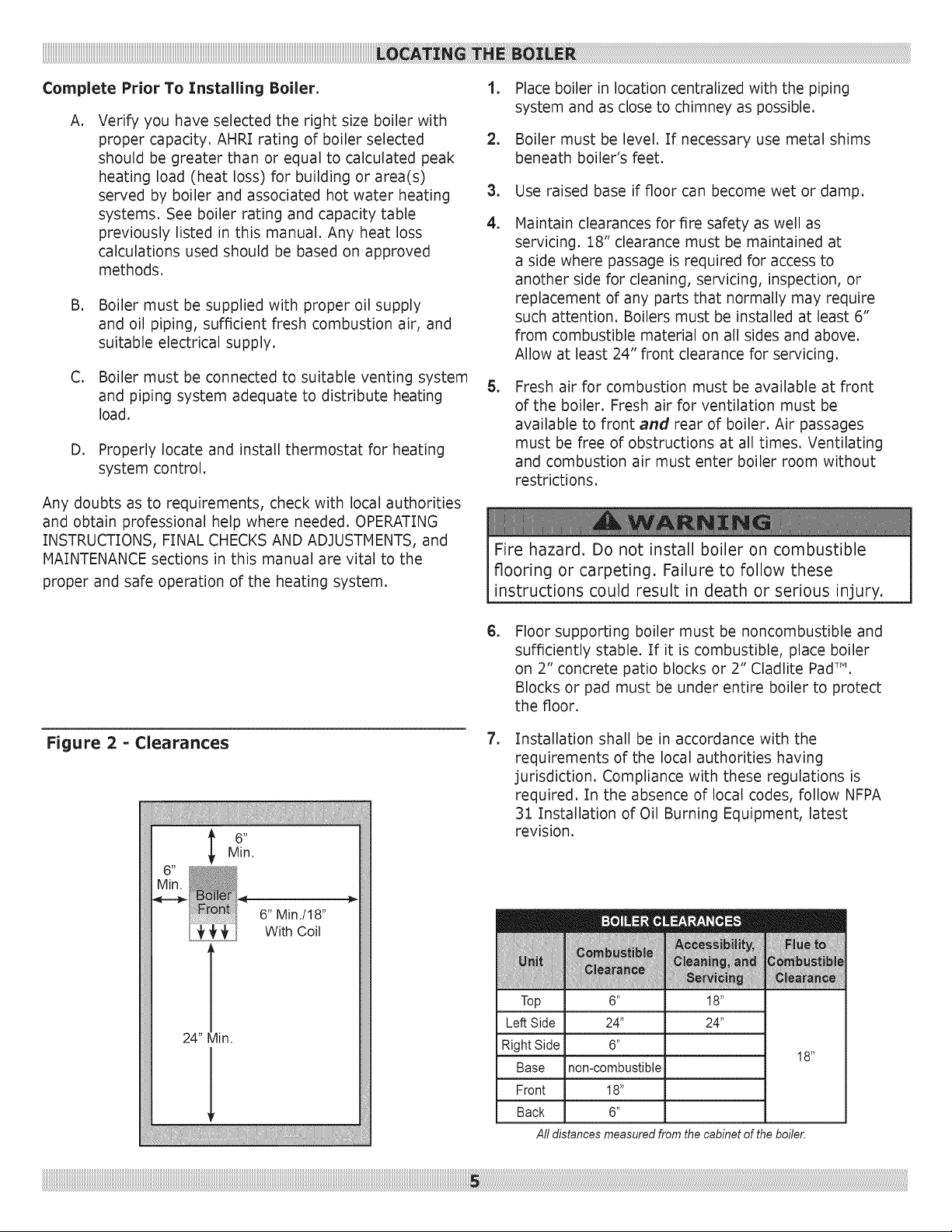
Maintain clearances for fire safety as well as
servicing. 18" clearance must be maintained at
a side where passage is required for access to
another side for cleaning, servicing, inspection, or
replacement of any parts that normally may require
such attention. Boilers must be installed at least 6"
from combustible material on all sides and above.
Allow at least 24" front clearance for servicing.
,
Fresh air for combustion must be available at front
of the boiler. Fresh air for ventilation must be
available to front and rear of boiler. Air passages
must be free of obstructions at all times. Ventilating
and combustion air must enter boiler room without
restrictions.
Fire hazard. Do not install boiler on combustible
flooring or carpeting. Failure to follow these
instructions could result in death or serious injury.
Figure 2 = Clearances
24" Min.
6" Min./l 8"
With Coil
,
Floor supporting boiler must be noncombustible and
sufficiently stable. If it is combustible, place boiler
on 2" concrete patio blocks or 2" Cladlite PadT",
Blocks or pad must be under entire boiler to protect
the floor.
, Installation shall be in accordance with the
requirements of the local authorities having
jurisdiction. Compliance with these regulations is
required. In the absence of local codes, follow NFPA
31 Installation of Oil Burning Equipment, latest
revision.
Top
Left Side
Right Side
Base
Front
Back
All distances measured from the cabinet of the boiler.
6 _
24"
non-combustible
18"
6"
18 _
24"
18 _
Page 6
MIN. 2" I.D.
VENT PIPE
OVERCURRENT
PROTECTED
SAFETY SWITCH
2" FILL
PIPE
ENTRANq
SWITCH
LINESTO
APPLIANCES
SERVICE LINE
ELECTRIC LINE
FILL VALVE
AND SHUTOFF
DIAPHRAGM
EXPANSION TANK
REGULATOR
VENT
PIPE
DRAFT
"11
m_
c
w
I
SHUT OFF
VALVE
OIL FILTER
OIL LINES J
OILTANK
TO OUTSIDE
TO RADIATION
OIL BURNER
FOUNDATIONS
RELIEFVALVE
CIRCULATING
PUMP IN
RETURN LINE
OR AFTER THE
EXPANSION
TANK
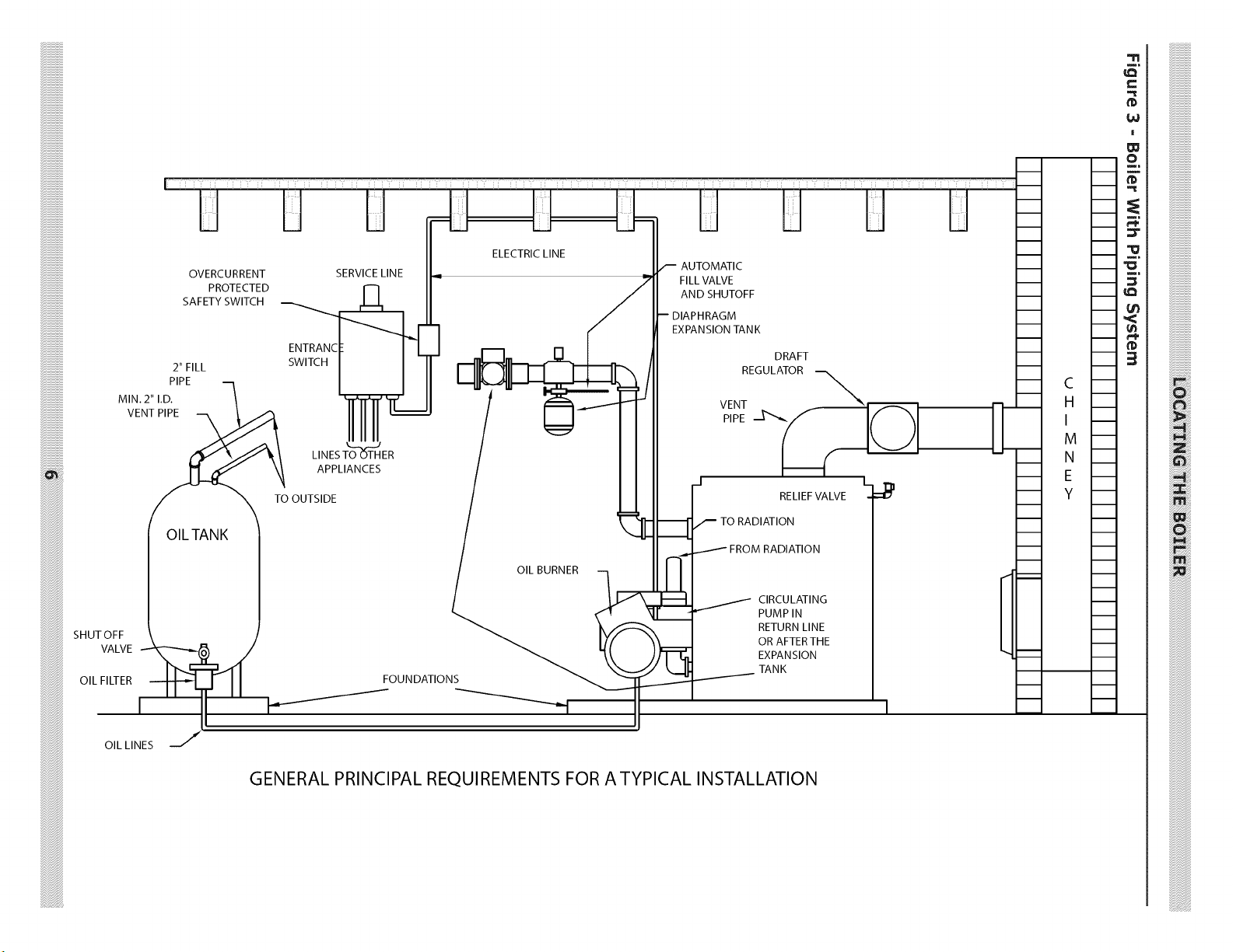
GENERAL PRINCIPAL REQUIREMENTS FOR A TYPICAL INSTALLATION
Page 7
EXAMPLE 2: Boiler Located in Confined Space
Asphyxiation, fire hazard. Do not obstruct air
openings to combustion area. Follow instructions
below, to maintain adequate combustion air.
Install outside air intake if you use fireplace or
kitchen or bathroom exhaust fan. These devices rob
boiler and water heater of combustion air.
Provide enough fresh air to assure proper combustion.
Fire in the boiler uses oxygen. It must have continuous
supply. Air in the house contains only enough oxygen to
supply burner for short time. Outside air must enter the
house to replace air used by the burner, Study the following
examples 1 and 2 to determine your fresh air requirements.
EXAMPLE 1: Boiler Located in Unconfined Space
If your boiler is in an open area (un-partitioned basement)
in conventional house, air that leaks through cracks around
doors and windows will usually be adequate to provide air
for combustion. Doors should not fit tightly. Do not caulk
cracks around windows.
An unconfined space is defined as space whose volume is
not less than 50 cubic feet per 1,000 Btu per hour of total
input rating of all appliances installed in that space.
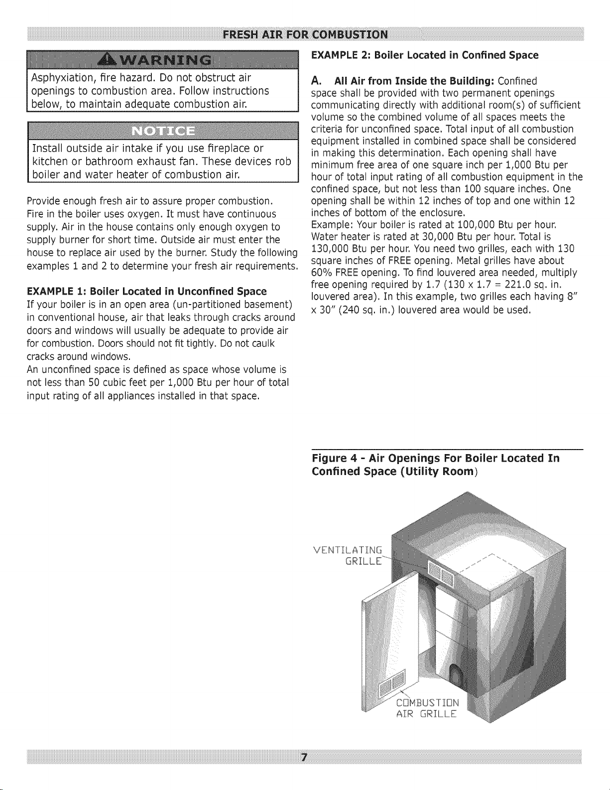
A, All Air from Inside the Building: Confined
space shall be provided with two permanent openings
communicating directly with additional room(s) of sufficient
volume so the combined volume of all spaces meets the
criteria for unconfined space. Total input of all combustion
equipment installed in combined space shall be considered
in making this determination. Each opening shall have
minimum free area of one square inch per 1,000 Btu per
hour of total input rating of all combustion equipment in the
confined space, but not less than 100 square inches. One
opening shall be within 12 inches of top and one within 12
inches of bottom of the enclosure.
Example: Your boiler is rated at 100,000 Btu per hour,
Water heater is rated at 30,000 Btu per hour, Total is
130,000 Btu per hour, You need two grilles, each with 130
square inches of FREEopening. Metal grilles have about
60% FREEopening. To find Iouvered area needed, multiply
free opening required by 1.7 (130 x 1.7 = 221.0 sq. in.
Iouvered area). In this example, two grilles each having 8"
x 30" (240 sq. in.) Iouvered area would be used.
Figure 4 - Air Openings For Boiler Located In
Confined Space (Utility Room)
VENTILATING
Page 8
B,
All Air from Outdoors: Confined space shall
be provided with two permanent openings, one
commencing within 12 inches of top and commencing
within 12 inches of bottom of enclosure. Openings
shall communicate directly, or by ducts, with outdoors
or spaces (crawl or attic) that freely communicate with
outdoors.
1. When directly communicating with outdoors, each
opening shall have minimum free area of one
3. When communicating with outdoors through
horizontal ducts, each opening shall have
minimum free area of one square inch per 2,000
Btu per hour of total input rating of all equipment
in the enclosure.
4. When ducts are used, they shall be of same cross
sectional area as free area of openings to which
they connect. Minimum dimension of rectangular
air ducts shall be not less than three inches.
square inch per 4,000 Btu per hour of total input
rating of all equipment in the enclosure.
2. When communicating with outdoors through
vertical ducts, each opening shall have minimum
free area of one square inch per 4,000 Btu per
hour of total input rating of all equipment in the
enclosure.
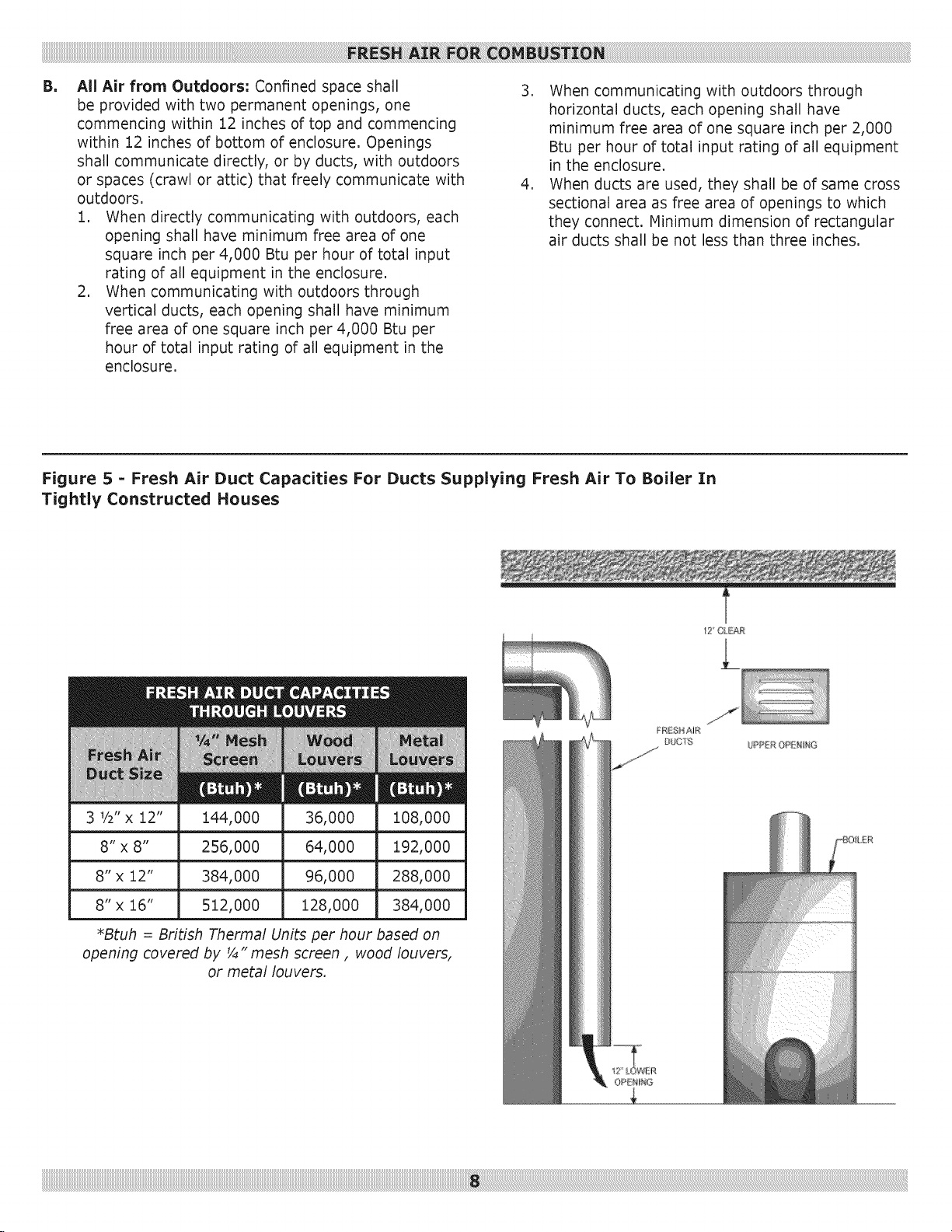
Figure 5 = Fresh Air Duct Capacities For Ducts Supplying Fresh Air To Boiler In
Tightly Constructed Houses
3 V2"x 12" 144,000 36,000 i08,000
8" x 8" 256,000 64,000 192,000
8" x 12" 384,000 96,000 288,000
8" x 16" 512,000 128,000 384,000
*Btuh = British Thermal Units per hour based on
opening covered by _" mesh screen, wood louvers,
or metal louvers.
12" CL£A£
Page 9
,
Installation of boiler for new heating system,
Install all of radiation units (panels, radiators,
baseboard, or tubing) and supply and return mains
first. After all heating system piping and components
have been installed, make final connection of system
piping to boiler. It is recommended to mount circulating
pump on supply side piping, such that it pumps away
from expansion tank. Refer to figures on next pages.
,
Equip hot water boiler installed above radiation
level with low water cut off device. Periodic inspection
is necessary, as is flushing of float type devices, per
low water cut off manufacturer's specific instructions.
,
Packaged boiler is set up with 1¼" NPT supply
and return piping from front of boiler. Boiler supply
and return piping can be moved to rear of boiler. Boiler
should not be piped return line to front, supply line
to rear, or vice versa, will cause boiler water to short
circuit heat exchanger. Piping connections may require
additional fittings and parts.
,
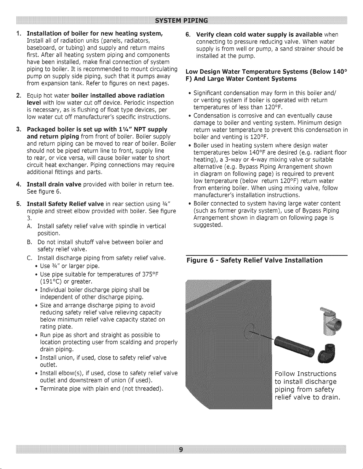
Install drain valve provided with boiler in return tee.
See figure 6.
,
Install Safety Relief valve in rear section using ¾"
nipple and street elbow provided with boiler. See figure
3.
A. Install safety relief valve with spindle in vertical
position.
B. Do not install shutoff valve between boiler and
safety relief valve.
C. Install discharge piping from safety relief valve.
• Use 3/4"or larger pipe.
• Use pipe suitable for temperatures of 375°F
(191°C) or greater.
• Individual boiler discharge piping shall be
independent of other discharge piping.
• Size and arrange discharge piping to avoid
reducing safety relief valve relieving capacity
below minimum relief valve capacity stated on
rating plate.
• Run pipe as short and straight as possible to
location protecting user from scalding and properly
drain piping.
• Install union, if used, close to safety relief valve
outlet.
• Install elbow(s), if used, close to safety relief valve
outlet and downstream of union (if used).
• Terminate pipe with plain end (not threaded).
,
Verify clean cold water supply is available when
connecting to pressure reducing valve. When water
supply is from well or pump, a sand strainer should be
installed at the pump.
Low Design Water Temperature Systems (Below 140 °
F) And Large Water Content Systems
• Significant condensation may form in this boiler and/
or venting system if boiler is operated with return
temperatures of less than 120°F.
• Condensation is corrosive and can eventually cause
damage to boiler and venting system. Minimum design
return water temperature to prevent this condensation in
boiler and venting is 120°F.
• Boiler used in heating system where design water
temperatures below 140°F are desired (e.g. radiant floor
heating), a 3=way or 4=way mixing valve or suitable
alternative (e.g. Bypass Piping Arrangement shown
in diagram on following page) is required to prevent
low temperature (below return 120°F) return water
from entering boiler. When using mixing valve, follow
manufacturer's installation instructions.
• Boiler connected to system having large water content
(such as former gravity system), use of Bypass Piping
Arrangement shown in diagram on following page is
suggested.
Figure 6 = Safety Relief Valve Installation
Follow Instructions
to install discharge
piping from safety
relief valve to drain.
iiiiiiiiiiiiiiiiiiiiiiiiiiiiiiiiiiiiiiiiiiiiiiiiiiiiiiiiiiiiiiiiiiiiiiiiiiiiiiiiiiiiiiiiiiiiiiiiiiiiiiiiiiiiiiiiiiiiiiiiiiiiiiiiiiiiiiiiiiiiiiiiiiiiiiiiiiiiiiiiiiiiiiiiiiiiiiiiiiiiiiiiiiiiiiiiiiiiiiiiiiiiiiiiiiiiiiiiiiiiiiiiiiiiiiiiiiiiiiiiiiiiiiiiiiiiiiiiiiiiiiiiiiiiiiiiiiiiiiiiiiiiiiiiiiiiiiiiiiiiiiiiiiiiiiiiiiiiiiiiiiiiiiiiiiiiiiiiiiiiiiiiiiiiiiiiiiiiiiiiiiiiiiiiiiiiiiiiiiiiiiiiiiiiiiiiiiiiiiiiiiiiiiiiiiiiiiiiiiiiiiiiiiiiiiiiiiiiiiiiiiiiiiiiiiiiiiiiiiiiiiiiiiiiiiiiiiiiiiiiiiiiiiiiiiiiiiiiiiiiiiiiiiiiiiiiiiiiiiiiiiiiiiiiiiiiiiiiiiiiiiiiiiiiiiiiiiiiiiiiiiiiiiiiiiiiiiiiiiiiiiiiiiiiiiiiiiiiiiiiiiiiiiiiiiiiiiiiiiiiiiiiiiiiiiiiiiiiiiiiiiiiiiiiiiiiiiiiiiiiiiiiiiiiiiiiiiiiiiiiiiiiiiiiiiiiiiiiiiiiiiiiiiiiiiiiiiiiiiiiiiiiiiiiiiiiiiiiiiiiiiiiiiiiiiiiiiiiiiiiiii_!!i!!i!!i!!i!!i!!i!!i!!i!!i!!i!!i!!i!!i!!i!!i!!i!!i!!i!!i!!i!!i!!i!!i!!i!!i!!i!!i!!i!!i!!i!!i!!i!!i!!i!!i!!i!!i!!i!!i!!i!!i!!i!!i!!i!!i!!i!!i!!i!!i!!i!!i!!i!!i!!i!!i!!i!!i!!i!!i!!i!!i!!i!!i!!i!!i!!i!!i!!i!!i!!i!!i!!i!!i!!i!!i!!i!!i!!i!!i!!i!!i!!i!!i!!i!!i!!i!!i!!i!!i!!i!!i!!i!!i!!i!!i!!i!!i!!i!!i!!i!!i!!i!!i!!i!!i!!i!!i!!i!!i!!i!!i!!i!!i!!i!!i!!i!!i!!i!!i!!i!!i!!i!!i!!i!!i!!i!!i!!i!!i!!i!!i!!i!!i!!i!!i!!i!!i!!i!!i!!i!!i!!i!!i!!i!!i!!i!!i!!i!!i!!i!!i!!i!!i!!i!!i!!i!!i!!i!!i!!i!!i!!i!!i!!i!!i!!i!!i!!i!!i!!i!!i!!i!!i!!i!!i!!i!!i!!i!!i!!i!!i!!i!!i!!i!!i!!i!!i!!i!!i!!i!!i!!i!!i!!i!!i!!i!!i!!i!!i!!i!!i!!i!!i!!i!!i!!i!!i!!i!!i!!i!!i!!i!!i!!i!!i!!i!!i!!i!!i!!i!!i!!i!!i!!i!!i!!i!!i!!i!!i!!i!!i!!i!!i!!i!!i!!i!!i!!i!!i!!i!!i!!i!!i!!i!!i!!i!!i!!i!!i!!i!!i!!i!!i!!i!!i!!i!!i!!i!!i!!i!!i!!i!!i!!i!!i!!i!!i!!i!!i!!i!!i!!i!!i!!i!!i!!i!!i!!i!!i!!i!!i!!i!!i!!i!!i!!i!!i!!i!!i!!i!!i!!i!!i!!i!!i!!i!!i!!i!!i!!i!!i!!i!!i!!i!!i!!i!!i!!i!!i!!i!!i!!i!!i!!i!!i!!i!!i!!i!!i!!i!!i!!i!!i!!i!!i!!i!!i!!i!!i!!i!!i!!i!!i!!i!!i!!i!!i!!i!!i!!i!!i!!i!!i!!i!!i!!i!!i!!i!!i!!i!!i!!i!!i!!i!!i!!i!!i!!i!!i!!i!!i!!i!!i!!i!!i!!i!!i!!i!!i!!i!!i!!i!!i!!i!!i_ii!ii!il!_!!i!
Page 10
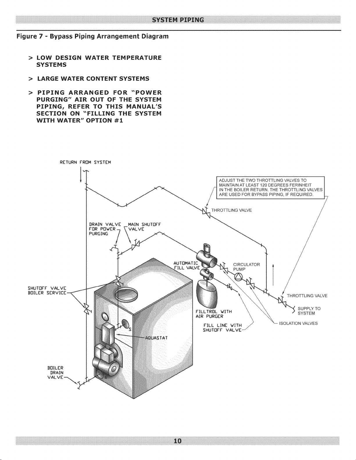
Figure 7 = Bypass Piping Arrangement Diagram
> LOW DESIGN WATER TEMPERATURE
SYSTEMS
> LARGE WATER CONTENT SYSTEMS
> PIPING ARRANGED FOR "POWER
PURGING" AIR OUT OF THE SYSTEM
PIPING! REFER TO THIS MANUAL'S
SECTION ON "FILLING THE SYSTEM
WITH WATER" OPTION #i
SHUTOFF VALVE
BOILER
AUTOMATIC
rILL VALVE
ADJUST THE TWO THROTTLING VALVES TO |
MAINTAIN AT LEAST 120 DEGREES FER_NHE_T
iN THE BOH_ER RETURN THE THROTTUNG VALP_ES
ARE USED FOR BYPASS PIPING, IF REQUIRED
THROTTLING VALVE
FILLTROL VITH
AIR PURGER
|
1
CIRCULATOR
PUMP
THROTTUNG VALVE
SUPPLY TO
SYSTEM
ISOL,AS_ON VALVES
Page 11
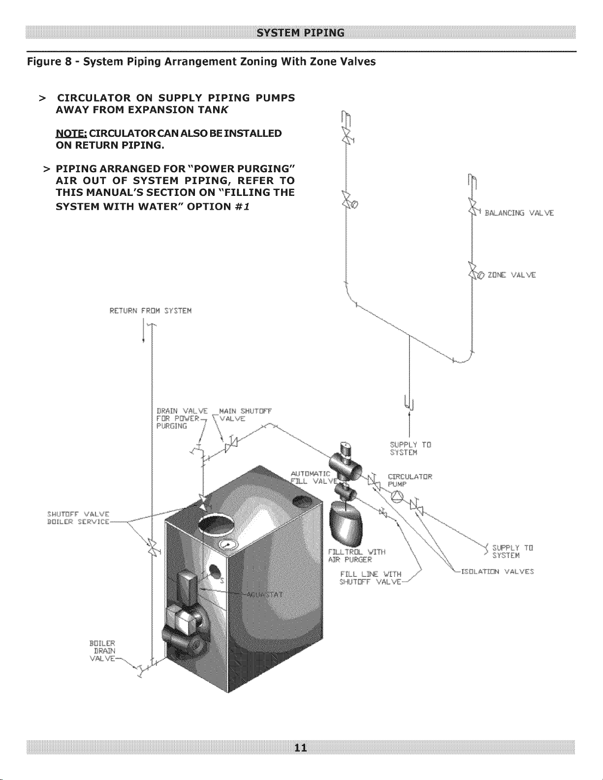
Figure 8 =System Piping Arrangement Zoning With Zone Valves
> CIRCULATOR ON SUPPLY PIPING PUMPS
AWAY FROM EXPANSION TANK
CIRCULATOR CAN ALSO BE INSTALLED
ON RETURN PIPING.
> PIPING ARRANGED FOR"POWER PURGING"
AIR OUT OF SYSTEM PIPING, REFER TO
THIS MANUAL'S SECTION ON "FILLING THE
SYSTEM WITH WATER" OPTION #1
© Z_£ VALVE
iiiiiiiiiiiiiiiiiiiiiiiiiiiiiiiiiiiiiiiiiiiiiiiiiiiiiiiiiiiiiiiiiiiiiiiiiiiiiiiiiiiiiiiiiiiiiiiiiiiiiiiiiiiiiiiiiiiiiiiiiiiiiiiiiiiiiiiiiiiiiiiiiiiiiiiiiiiiiiiiiiiiiiiiiiiiiiiiiiiiiiiiiiiiiiiiiiiiiiiiiiiiiiiiiiiiiiiiiiiiiiiiiiiiiiiiiiiiiiiiiiiiiiiiiiiiiiiiiiiiiiiiiiiiiiiiiiiiiiiiiiiiiiiiiiiiiiiiiiiiiiiiiiiiiiiiiiiiiiiiiiiiiiiiiiiiiiiiiiiiiiiiiiiiiiiiiiiiiiiiiiiiiiiiiiiiiiiiiiiiiiiiiiiiiiiiiiiiiiiiiiiiiiiiiiiiiiiiiiiiiiiiiiiiiiiiiiiiiiiiiiiiiiiiiiiiiiiiiiiiiiiiiiiiiiiiiiiiiiiiiiiiiiiiiiiiiiiiiiiiiiiiiiiiiiiiiiiiiiiiiiiiiiiiiiiiiiiiiiiiiiiiiiiiiiiiiiiiiiiiiiiiiiiiiiiiiiiiiiiiiiiiiiiiiiiiiiiiiiiiiiiiiiiiiiiiiiiiiiiiiiiiiiiiiiiiiiiiiiiiiiiiiiiiiiiiiiiiiiiiiiiiiiiiiiiiiiiiiiiiiiiiiiiiiiiiiiiiiiiiiiiiiiiiiiiiiiiiiiiiiiiiiiiiiiiiiiiiiiiiiiiiiiiiiiiiiiii!_i!ii!ii_i!i!ii!ii!ii!ii!ii!ii!ii!ii!ii!ii!ii!ii!ii!ii!ii!ii!ii!ii!ii!ii!ii!ii!ii!ii!ii!ii!ii!ii!ii!ii!ii!ii!ii!ii!ii!ii!ii!ii!ii!ii!ii!ii!ii!ii!ii!ii!ii!ii!ii!ii!ii!ii!ii!ii!ii!ii!ii!ii!ii!ii!ii!ii!ii!ii!ii!ii!ii!ii!ii!ii!ii!ii!ii!ii!ii!ii!ii!ii!ii!ii!ii!ii!ii!ii!ii!ii!ii!ii!ii!ii!ii!ii!ii!ii!ii!ii!ii!ii!ii!ii!ii!ii!ii!ii!ii!ii!ii!ii!ii!ii!ii!ii!ii!ii!ii!ii!ii!ii!ii!ii!ii!ii!ii!ii!ii!ii!ii!ii!ii!ii!ii!ii!ii!ii!ii!ii!ii!ii!ii!ii!ii!ii!ii!ii!ii!ii!ii!ii!ii!ii!ii!ii!ii!ii!ii!ii!ii!ii!ii!ii!ii!ii!ii!ii!ii!ii!ii!ii!ii!ii!ii!ii!ii!ii!ii!ii!ii!ii!ii!ii!ii!ii!ii!ii!ii!ii!ii!ii!ii!ii!ii!ii!ii!ii!ii!ii!ii!ii!ii!ii!ii!ii!ii!ii!ii!ii!ii!ii!ii!ii!ii!ii!ii!ii!ii!ii!ii!ii!ii!ii!ii!ii!ii!ii!ii!ii!ii!ii!ii!ii!ii!ii!ii!ii!ii!ii!ii!ii!ii!ii!ii!ii!ii!ii!ii!ii!ii!ii!ii!ii!ii!ii!ii!ii!ii!ii!ii!ii!ii!ii!ii!ii!ii!ii!ii!ii!ii!ii!ii!ii!ii!ii!ii!ii!ii!ii!ii!ii!ii!ii!ii!ii!ii!ii!ii!ii!ii!ii!ii!ii!ii!ii!ii!ii!ii!ii!ii!ii!ii!ii!ii!ii!ii!ii!ii!ii!ii!ii!ii!ii!ii!ii!ii!ii!ii!ii!ii!ii!ii!ii!ii!ii!ii!ii!ii!ii!ii!ii!ii!ii!ii!ii!ii!ii!ii!ii!ii!ii!ii!ii!ii!ii!ii!ii!ii!ii!ii!ii!ii!ii!ii!ii!ii!ii!ii!ii!ii!ii!ii!ii!ii!ii!ii!ii!ii!ii!ii!ii!ii!ii!ii!ii!ii!ii!ii
Page 12
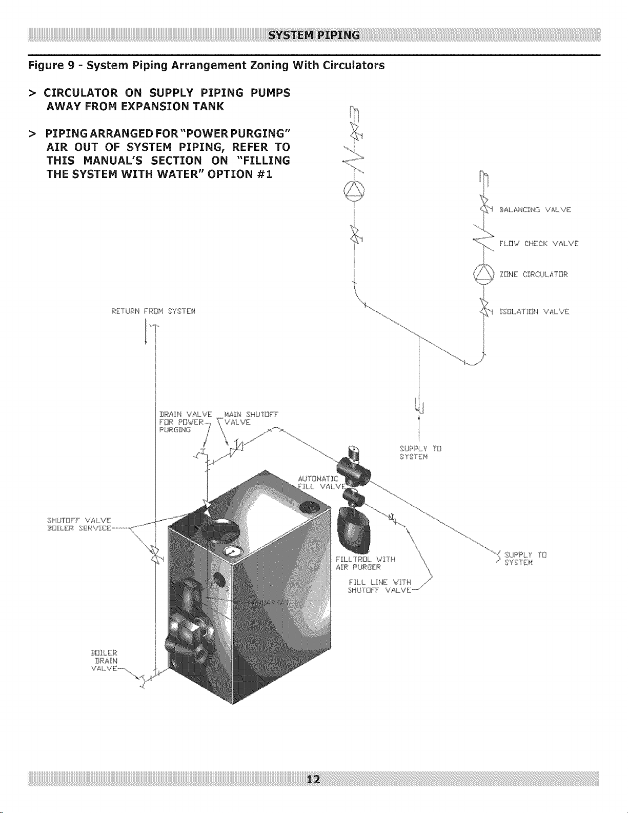
Figure 9 = System Piping Arrangement Zoning With Circulators
> CIRCULATOR ON SUPPLY PIPING PUMPS
AWAY FROM EXPANSION TANK
> PIPING ARRANGED FOR"POWER PURGING"
AIR OUT OF SYSTEM PIPINGI REFER TO
THIS MANUAL'S SECTION ON "FILLING
THE SYSTEM WITH WATER" OPTION #1
B_L_A bK/IN/I V AL "dE;
FLHW CHECK VALVE
ZOI_@E OIRCUL #_TQR
F_E"_ _:_N FROM SYS _EN
T_HL AT[ON 'VALVE:
gJPPL1
" SYSTD4
iiiiiiiiiiiiiiiiiiiiiiiiiiiiiiiiiiiiiiiiiiiiiiiiiiiiiiiiiiiiiiiiiiiiiiiiiiiiiiiiiiiiiiiiiiiiiiiiiiiiiiiiiiiiiiiiiiiiiiiiiiiiiiiiiiiiiiiiiiiiiiiiiiiiiiiiiiiiiiiiiiiiiiiiiiiiiiiiiiiiiiiiiiiiiiiiiiiiiiiiiiiiiiiiiiiiiiiiiiiiiiiiiiiiiiiiiiiiiiiiiiiiiiiiiiiiiiiiiiiiiiiiiiiiiiiiiiiiiiiiiiiiiiiiiiiiiiiiiiiiiiiiiiiiiiiiiiiiiiiiiiiiiiiiiiiiiiiiiiiiiiiiiiiiiiiiiiiiiiiiiiiiiiiiiiiiiiiiiiiiiiiiiiiiiiiiiiiiiiiiiiiiiiiiiiiiiiiiiiiiiiiiiiiiiiiiiiiiiiiiiiiiiiiiiiiiiiiiiiiiiiiiiiiiiiiiiiiiiiiiiiiiiiiiiiiiiiiiiiiiiiiiiiiiiiiiiiiiiiiiiiiiiiiiiiiiiiiiiiiiiiiiiiiiiiiiiiiiiiiiiiiiiiiiiiiiiiiiiiiiiiiiiiiiiiiiiiiiiiiiiiiiiiiiiiiiiiiiiiiiiiiiiiiiiiiiiiiiiiiiiiiiiiiiiiiiiiiiiiiiiiiiiiiiiiiiiiiiiiiiiiiiiiiiiiiiiiiiiiiiiiiiiiiiiiiiiiiiiiiiiiiiiiiiiiiiiiiiiiiiiiiiiiiiiiiiiiii__!i!!!_iiiii!i!_i!_i!_i!_i!_i!_i!_i!_i!_i!_i!_i!_i!_i!_i!_i!_i!_i!_i!_i!_i!_i!_i!_i!_i!_i!_i!_i!_i!_i!_i!_i!_i!_i!_i!_i!_i!_i!_i!_i!_i!_i!_i!_i!_i!_i!_i!_i!_i!_i!_i!_i!_i!_i!_i!_i!_i!_i!_i!_i!_i!_i!_i!_i!_i!_i!_i!_i!_i!_i!_i!_i!_i!_i!_i!_i!_i!_i!_i!_i!_i!_i!_i!_i!_i!_i!_i!_i!_i!_i!_i!_i!_i!_i!_i!_i!_i!_i!_i!_i!_i!_i!_i!_i!_i!_i!_i!_i!_i!_i!_i!_i!_i!_i!_i!_i!_i!_i!_i!_i!_i!_i!_i!_i!_i!_i!_i!_i!_i!_i!_i!_i!_i!_i!_i!_i!_i!_i!_i!_i!_i!_i!_i!_i!_i!_i!_i!_i!_i!_i!_i!_i!_i!_i!_i!_i!_i!_i!_i!_i!_i!_i!_i!_i!_i!_i!_i!_i!_i!_i!_i!_i!_i!_i!_i!_i!_i!_i!_i!_i!_i!_i!_i!_i!_i!_i!_i!_i!_i!_i!_i!_i!_i!_i!_i!_i!_i!_i!_i!_i!_i!_i!_i!_i!_i!_i!_i!_i!_i!_i!_i!_i!_i!_i!_i!_i!_i!_i!_i!_i!_i!_i!_i!_i!_i!_i!_i!_i!_i!_i!_i!_i!_i!_i!_i!_i!_i!_i!_i!_i!_i!_i!_i!_i!_i!_i!_i!_i!_i!_i!_i!_i!_i!_i!_i!_i!_i!_i!_i!_i!_i!_i!_i!_i!_i!_i!_i!_i!_i!_i!_i!_i!_i!_i!_i!_i!_i!_i!_i!_i!_i!_i!_i!_i!_i!_i!_i!_i!_i!_i!_i!_i!_i!_i!_i!_i!_i!_i!_i!_i!_i!_i!_i!_i!_i!_i!_i!_i!_i!_i!_i!_i!_i!_i!_i!_i!_i!_i!_i!_i!_i!_i!_i!_i!_i!_i!_i!_i!_i!_i!_i!_i!_i!_i!_i!_i!_i!_i!_i!_i!_i!_i!_i!_i!_i!_i!_i!_i!_i!_i!_i!_i!_i!_i!_i!_i!_i!_i!_i!_i!_i!_i!_i!_i!_i!_i!_i!_i!_i!_i!_i!_i!_i!_i!i_i!!
Page 13
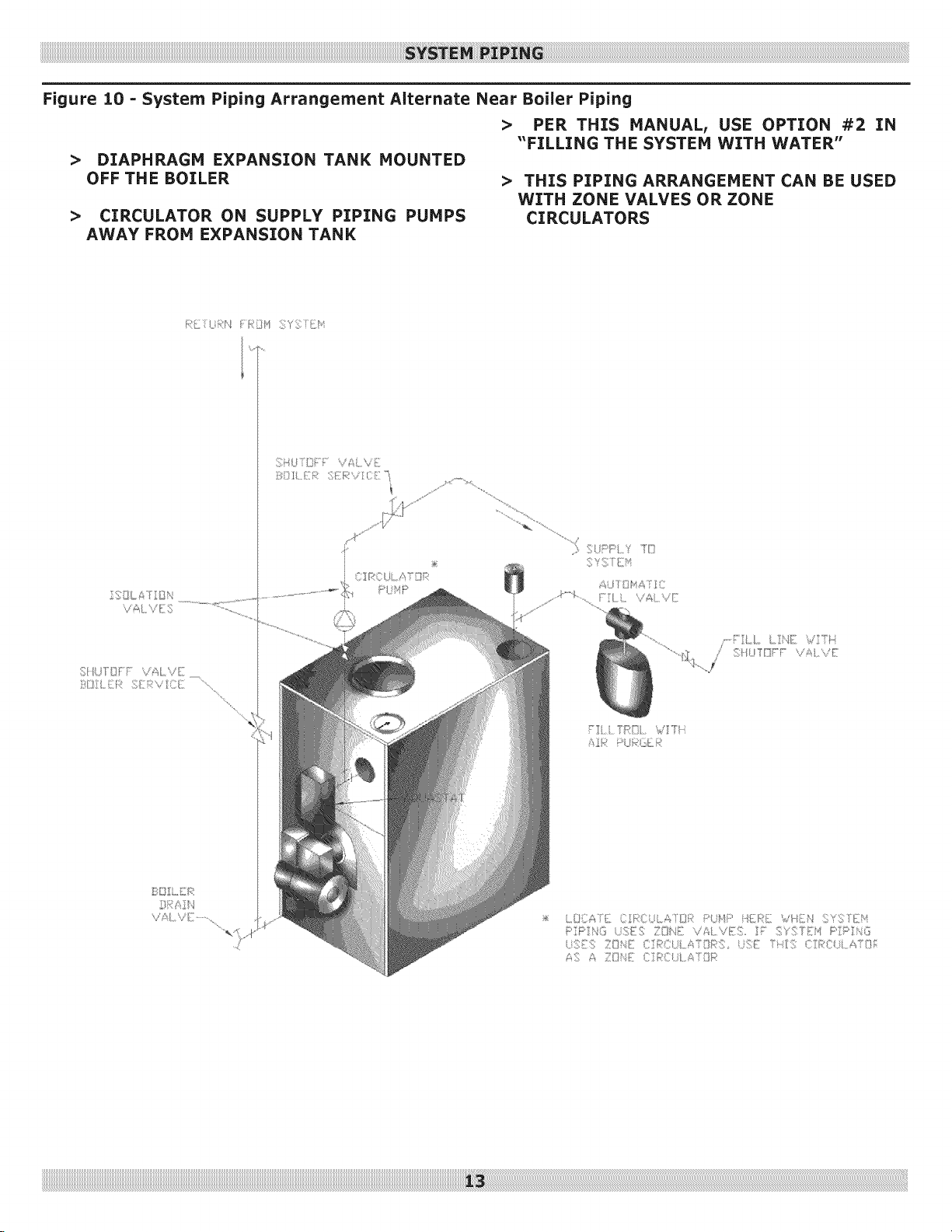
Figure 10 = System Piping Arrangement Alternate Near Boiler Piping
> PER THIS MANUALI USE OPTION #2 IN
"FILLING THE SYSTEM WITH WATER"
>
DIAPHRAGH EXPANSION TANK HOUNTED
OFF THE BOILER
> THIS PIPING ARRANGEMENT CAN BE USED
WITH ZONE VALVES OR ZONE
>
CIRCULATOR ON SUPPLY PIPING PUMPS
CIRCULATORS
AWAY FROM EXPANSION TANK
F] i TRIll / Ti
=If i Ui:;;
Tankless Coil Piping Arrangement
Boilersmay be factorypackaged with tankless heater
coil see figure below. Coil provides instantaneous heating
of water for domestic use if proper burner and water supply
line controls are used. Tankless coils are meant to provide
domestic hot water for intermittent draws, not continuous
flow.
Do not use tankless coil if your water is excessively
hard with lime or other deposits which will
accumulate inside the coil.
When using tankless coil, boiler is configured so Honeywell
L7248 operates with Honeywell L4006 low limit mounted
on well installed in tankless heater. Mount factory wired low
limit on well.
Tempering valve (mixing valve) is recommended as shown
below. Flow restrictor may be required on tankless coil inlet
piping so that flow rates are matched to boiler heat input
(see table).
Water temperatures exceeding 125°F will cause
severe burns instantly or death by scalding.
!m
3EW.65
3EW.75
3EW1.00
4EW.90
4EW1.25
4EW1.50
5EW1.20
5EW1.75
-1:Gallons of water per minute heated from 40 °F to 140°F with
200 °F boiler water temperature, intermittent draw
0.65
0.75
1.00
0.90
1.25
1.50
1.20
1.75 4.00
91
105
140
126
175
210
168
245
2.90
3.00
3.25
3.15
3.50
3.75
3.45
Figure 11 =Tankless Coil Piping Arrangement
Lit,_TEMPERES H_T _TATER
AU OMAT]C D_SHWAt!tHER ECT
TAI', KLESS COIL
CENTER LINE
OF COLD TAP
LII'4IT
CBNTRBL
t
TEMPERING
VA VE
SHU T- OFF
VALVE
TEPPERED HOT
WATER
COLD WATER
ZNLET
Page 15

Antifreeze added to boilers must be nontoxic, and
must be of type specifically intended for use in closed
hydronic heating systems, Under no circumstances
should automotive antifreeze be used, Antifreeze used
in any boiler may reduce capacity by 10% or more and
increase fuel consumption, Tankless coil performance
will fall as concentration of antifreeze is increased, Refer
to boiler and piping water volumes tables,
3 9.6
4 11.6
5 13.7
½" 82.5 63.5
¾" 40.0 36.0
1" 23.3 22.2
1 ¼" 15.3 12.8
1 ½" 10.8 9.5
2" 6.2 5.8
Divide total length of piping in feet by appropriate factor
in table to determine volume in gallons,
Page 16

For oil fired boilers for connections to vents or chimneys,
vent installations shall be in accordance with applicable
provisions of INSTALLATION OF OIL BURNING EQUIPMENT,
NFPA31 latest revision, and applicable provisions of local
building codes.
Fire Hazard. Maintain minimum vent pipe clearance
of 18" from surface of vent to wood and other
combustible materials. Failure to comply may result
in death or serious injury.
Fresh air (ventilation) is important to proper
venting. Ventilation and venting are two parts of the
same system. Inadequate ventilation will result in
inadequate venting. Always be sure to have enough
ventilation to support proper venting.
Check your chimney to make certain that it is right size,
properly constructed and in good condition.
See Table "Recommended Minimum Chimney Sizes".
For additional chimney design and sizing information,
consult the National Standard for Chimneys, Fireplaces,
Vents and Solid Fuel Burning Appliances, ANSI/NFPA 211.
Chimney Connector And Draft Regulator
• Venting the boiler requires 6" diameter chimney
connector pipe and use of manufacturer provided draft
regulator.
• Regulator, when properly installed, automatically
controls the draft.
• Install in horizontal section of pipe, may also be
installed in angled or vertical section of pipe.
• Verify "top" of regulator is at the top and short pipe
section which holds the vane is horizontal.
• Even though locating draft regulator close to chimney
reduces noise, install draft regulator as close as
practicable to the boiler,
• Install chimney connector, start at boiler with vertical
pipe, elbow, then install draft regulator horizontally.
• When regulator is in place, start at chimney and work
back to the regulator.
• Join the two sections with draw-band.
• Horizontal pipe must slope up toward the chimney at
least 1/4, inch per linear foot of venting.
• Chimney connector must not leak and must be firmly
supported.
• Join each section with at least two sheet metal screws.
Support every second section with a stovepipe wire.
0.60 1.30 15 8"x8"
1.31 1.80 15 8"x8"
1.81 2.00 20 8" x 8"
For elevations above 2,000 feet above sea level, add 3 feet to the chimney heights.
6" 6 ¾"x 6 ¾"
7" 6 ¾"x 6 ¾"
8" 6 ¾"x 6 ¾"
Page 17

Figure 12 -Typical Chimney Connection
\
MUST BE AT LEAST
INCHES THICK -
AND BE
HUST SLOPE UP
AT LEAST I/4, INCH
PER KOOT OF
HORZZONTALo
s
MINIMUM HEIGHT:
MuST SEAT LEAST 3 FT
HIGHER THAN HIGHEST PART OF
PASSAGE THROUGH ROOE MUST BE
AT LEAST 2 FT HIGHER THAN ANY
NEIGHBORING OBJECT WITHIN 10 FT.
MUST HAVE AN UNOBSTRUCTED
TOP OPENING
IN
THIHBLE
BRAF REGULATOR
VANE
ALTERNATE POSITIONS
Page 18

Electrical shock hazard. Turn OFF electrical power supply
at service panel before making electrical connections.
Failure to do so could result in death or serious injury.
Thermostat
Install 24 Volt thermostat (not provided) in proper location.
Location of thermostat has effect on boiler system operation.
Follow instructions included with thermostat.
Grounding
Permanently ground boiler according to local codes and
latest revision of the National Electrical Code. Run 14
gauge or heavier copper wire from boiler to grounded
connection in service panel or properly driven and
electrically grounded ground rod.
Electric Power Supply
Installation must comply with the latest revision of the
National Electrical Code, any other national, state, or local
codes or regulations.
Connect 115 volt electrical supply to L1 and L2 terminals
on limit and two thermostat wires to T and T terminals on
same limit. See wiring diagram page 28.
Run separate circuit from separate over current protection
device in your electrical service entrance panel. Minimum
15 ampere circuit. Locate shutoff switch at boiler. Turn off
during any maintenance. Solder and tape or securely fasten
connections with wire nuts.
Oil Burner Wiring
For boilers packaged with oil burners, burners are wired
at the factory. For boilers shipped without a burner, wiring
connections are shown in the electrical wiring diagrams of
this manual.
Page 19

How A Hot Water System Operates
Entire heating system (boiler, piping, and radiation units)
is filled with water. As water in the boiler is heated, it
is circulated from top of boiler through supply main to
radiation units. Cooler water in radiation units flows back
through return piping through return main into the boiler.
This arrangement provides positive and rapid response to
the thermostat.
Filling The System With Water
OPTION #1 This method utilizes boiler piping as shown in
figure on page 6.
A!
main shutoff valve, isolation valves, and zone
valves (if applicable). If bypass piping is installed,
also close two throttling valves. Leave boiler service
shutoff valve (if installed) and balancing valves to
each heating zone _.
B!
._ following valves in order: drain valve for power
purging, isolating valves before and after boiler
circulator (if applicable), both throttling valves (if
applicable), and then open fill line shutoff valve. Water
will fill bypass piping and push air through piping and
out power purging drain valve. When power purging
drain valve runs air free, close bypass piping throttling
valve (leaving throttling valve to supply piping fully
open).
OPTION #2
• Close air vents on all radiation units.
• Open valves to radiation units. Verify boiler drain valve,
expansion tank drain cock, and air bleed screw on
expansion tank drain fitting are closed.
• Open fill valve on piping to expansion tank.
• Open water inlet to boiler and leave it open.
• Open air vent on lowest radiation unit.
• When all air has escaped and water starts to flow from
vent, close it.
• Go to next radiation unit, and repeat this process until
finishing with highest radiation unit.
• If heating system has automatic vents, this manual
venting is unnecessary but it will speed up proper filling
of the system.
If system is a closed expansion tank system, automatic fill
valve is needed. Leave automatic fill valve open to refill
system automatically as needed.
Note initial fill pressure on boiler's temperature / pressure
gauge, which should be 10-15 psig. Any lowering of
pressure from its initial fill pressure indicates loss of water
due to leakage. Automatic fill valve should then compensate
for this water pressure loss. If it does not, manually open
this valve to refill system until needle is again pointing to
same pressure reading. Instructions are packaged with
valve.
C,
Next, _ isolation valve (or zone valve) to first
zone. Water will fill piping and push any air out power
purging drain valve. When power purging drain valve
runs air free, close isolation valve or zone valve).
Repeat this procedure for remaining heating zones.
D,
Once all zones are filled with water and purged of air,
power purging drain valve and fill line shut off
valve, _ main shutoff valve, and _ throttling
valves and balancing valves as required.
Page 20

Start: Fill entire system with water. Vent all air from
system following section for Filling The Boiler.
Fuel
Units And Oil Lines:
o
Install oil line(s) to oil burner.
o
Recommend using heavy wall copper tubing and
flared fittings, not compression fittings.
All connections and joints must be absolutely airtight.
Use an appropriate non=hardening thread sealing
compound on the threaded connections, not Teflon
tape.
See fuel unit data sheet furnished with the burner for
sizing, lift, and length of tubing recommendations.
Oil burner is equipped with single stage fuel unit
with bypass plug removed for single pipe installation.
Satisfactory where fuel supply is on same level as or
above burner permitting gravity flow of oil. Per NFPA 31
requirements, never exceed 3 psig pressure to inlet side of
fuel unit.
When necessary to lift oil to burner, two pipe installation
is required. Run return line between fuel unit and oil
supply. When two pipe installation is used, bypass plug
(furnished with burner) must be installed in fuel unit. Refer
to fuel unit instructions furnished with burner for specific
instructions on installing bypass plug. Do not exceed fuel
unit manufacturer's recommendations for running vacuum.
If lift exceeds 14 feet for Beckett or Carlin burners
or 11 feet for Riello burners, two stage fuel unit is
required with return line.
Air Supply For Combustion;
• Do not install boiler in rooms with insufficient air, unless
corrective steps are taken.
• It may be necessary to install windows or cut holes in
a door to rooms used for supply air to obtain sufficient
combustion air and prevent less than atmospheric air
pressure in that room.
• If there is a lack of combustion air, burner flame will be
dark orange and formation of soot will occur in heating
unit.
• In buildings of conventional frame, brick, or stone
construction that do not have utility rooms, basement
windows, or stair doors, air infiltration is normally
adequate to provide enough air for combustion and for
operation of barometric draft control.
• Room used for supplying combustion air should be
isolated from any area served by exhaust fans.
• Refer back to the section on Fresh Air For Combustion
for additional sizing guidelines.
Draft Regulators: Barometric draft regulator is required
for controlling draft through boiler. Mount barometric draft
regulator in chimney connector. Refer back to section on
"Chimney And Chimney Connections". Once draft regulator
is installed, use draft gauge to adjust to proper opening:
A. Combustion chamber over fire draft will be
approximately 0.01" WC to 0.02" WC.
B. Stack draft will be approximately 0.02" WC. to
0.04" WC.
C. Larger installation, greater draft will be required in
stack to obtain desired over fire draft.
Install oil filter of adequate size inside building between
tank shutoff valve and oil burner. For ease of servicing,
locate shutoff valve and filter near oil burner.
Page 21

NozzlesAnd Electrodes: Use proper size, spray angle,
and spray pattern nozzle. Refer to recommended nozzle
selection charts.
To install nozzle, remove nozzle line electrode assembly,
if necessary remove retention ring assembly, and install
and tighten nozzle. Take care not to damage electrode
insulators or bend electrode tips.
After installing nozzle, reassemble nozzle line electrode
assembly and set electrode tip spacing.
Depending on burner type, electrode tip spacing may
need to be set prior to reassembling nozzle line electrode
assembly.
Refer to following pages for setting electrode tip spacing.
Final Burner Adjustments: Final burner adjustments
must be made using combustion test instruments. Refer to 3.
"Burner Settings". Set burner accordingly.
• Check draft over fire to verify it is between 0.01" WC 4.
and 0.02" WC, adjust draft as necessary.
• After operating 10 minutes to warm up boiler, use
combustion test equipment to take smoke reading in
flue pipe between boiler and draft regulator. 5.
• Smoke reading should be zero to trace (Shell Bacharach
Scale).
• A new boiler requires more than 10 minutes to burn 6.
clean due to oil film on new heat exchanger.
• If smoke reading is zero, gradually close burner's air
adjustment to obtain smoke reading showing trace
smoke reading. Once smoke reading is trace, measure
CO2and as insurance margin increase air to sufficiently
reduce CO2by 1/2% to 1%.
If clean fire cannot be obtained, it is necessary to verify
burner head and electrode alignment. Proper electrode
alignment figures are presented on following pages. If
fire continues to be smoky, replace nozzle with correct
replacement.
Once burner is completely adjusted, burner should
be started and stopped several times to assure good
operation with no fluttering or rumbling. Verify there
are no oil leaks and record nozzle size, oil pressure,
combustion readings, and air settings on tag or label
attached to burner or, boiler.
Oil Burner Maintenance= For Beckett AFG, Carlin EZ1
or EZ2, and the Riello 40 F3, F5, or F10 perform following
preventative maintenance annually, preferably prior to
heating season.
1.
Oil Burner Motor For Beckett and Carlin burners,
add 2 - 3 drops of non-detergent electric motor oil to
each oil cup located at front and rear of motor (Riello
burners are permanently lubricated). Excessive oiling
will shorten life expectancy of motor.
2.
Fuel Filter Replace to prevent contaminated fuel from
reaching nozzle. Partially blocked fuel filter can cause
premature failure of fuel pump.
Fuel Pump Unit Replace pump screen and clean pump
unit to maintain fuel delivery to nozzle.
Ignition Electrodes Clean and adjust per
manufacturer's recommendations, to maintain reliable
ignition of oil.
Nozzle Replace to maintain safe and reliable
combustion efficiency. Replace with nozzle as required
in charts located in this manual.
Fan and Blower Housing Must be kept clean, free of
dirt, lint and oil to maintain proper amount of air fuel
requires to burn.
7. Check Final Burner Adjustments.
If any component parts must be replaced, always use parts
recommended by burner manufacturer.
Page 22

Figure 13 =Burner Adjustments and Settings
4',F5 UW",,/EF/ /AA]ASL_ (V)l/ AI}S
_8 LiE_ D 41-24S£/}N #, Di_4E_SI lhl_
_.._..KEIT AFG /AAIAf:>L,L F_EAZ ADjjS"I"F'Et',TSAND ,.E T L ,:t,s
'\ DIME;NS ::]i,;q'q"
SEE A O/E
Page 23

Burn, scald hazard. Do not attempt to start the
burner when excess oil has accumulated, when
the unit is full of vapor, or when the combustion
chamber is very hot.
Locate thermostat five feet above the floor on inside wall.
Locate thermostat to sense average room temperature,
avoid the
You or your installer must follow these instructions
carefully.
Adjust Operating Controls: Use the following settings
for first adjustment:
High Limit:
Baseboard and Convectors 200°F
Standing Radiators 180°F
Low Limit (when used) 1400 ( increase if hotter domestic
water is required, low limit set point must be at least 20°F less
than high limit set point)
Adjust Thermostat Heat Anticipator To: 0.2
Amps
Check Thermostat Operation:
Follow instructions included with your thermostat.
Behind
doors
Fireplace
TV sets
Radios
Concealed pipes
Corners &
alcoves
Lamps
Direct sunlight
Kitchens
When temperature on thermostat is set above indicated
thermostat temperature, boiler's burner should start. Verify
that when room temperature reaches selected temperature
setting, thermostat should turn boiler's burner off, and once
room temperature falls few degrees boiler starts operating
again.
Do not start burner unless all cleanout doors are
secured in place.
Concealed pipes
or ducts
Stairwells drafts
Doors drafts
Unheated room
on other side of
wall
Page 24

Annually: Recommend flue passages, combustion
chamber area (target wall, fire door insulation,
durablanket), burner adjustment, control operation, and
boiler seals (fire door gasket or silicone seal, cast iron
sectional seals, flue collector) be checked once each year
by trained Service Technician.
Diaphragm Expansion Tank-" Tank may become
water logged. Frequent automatic opening of safety relief
valve indicates water logging. High boiler temperature
accompanied by unusually low radiation unit temperature
(and "knocking" noises) indicates excess air in the tank. To
correct this condition, replace diaphragm expansion tank.
Before The Start Of Each Heating Season (or when
system has been shut down for extended periods of time)
recheck whole system for water, oil, and vent piping leaks.
Replace or patch any leaks or faulty seals.
Vent Pipe= Visually inspect entire venting system once a
month for any signs of leakage, deterioration, or soot build
up. If vent pipe shows any signs of leaking or deterioration,
replace it immediately. If it shows any signs of soot
build up, clean vent pipe and have burner settings and
combustion checked by trained Service Technician.
Safety Relief Valve= Valve should open automatically
when system pressure exceeds pressure rating (usually 30
psi) of safety relief valve. Should valve ever fail to open
under this condition, shut down the system, Drain system
until system pressure is reduced below safety relief valve
pressure rating, Contact Service Technician to replace the
valve and inspect heating system to determine cause, may
indicate equipment malfunction, Safety relief valve should
be tested monthly during heating season, Prior to testing,
make certain discharge pipe is properly connected to valve
outlet and arranged so as to contain and safely dispose of
boiler discharge, Hold trip lever fully open for at least five
seconds in order to flush free any sediment that may lodge
on valve seat. Permit valve to snap shut. Refer to valve
manufacturer's instructions packaged for more details,
Water System: If system is to remain out of service
during freezing weather, drain it completely (water left in
system may freeze and will crack pipes and/or boiler).
Tankless Coil (Or Cover Plate) Gasket: Gasket
should be checked at least twice year for leakage, replace if
necessary. If gasket is replaced, make sure that when coil
plate (or cover plate) is reattached, ten nuts are torqued
in alternating pattern to insure equal force is applied to
entire gasket creating good seal. Nuts should be torqued so
gasket does not squeeze out from behind the plate.
Oil Burner= Oil burner maintenance is listed in this
manual under "Operating The Boiler".
Never burn garbage or paper in the unit, never leave
combustible material around it.
Conventional Expansion Tank: Tank may become
water logged or may receive excess air, Frequent automatic
opening of safety relief valve indicates water logging, High
boiler temperature accompanied by unusually low radiation
unit temperature (and "knocking" noises) indicates excess
air in the tank, To correct either condition, close valve
between boiler and tank. Drain tank until empty, Check all
tank plugs and fittings, tighten as necessary, Open valve
between boiler and tank, Water will rise to normal height in
tank if system has automatic fill valve, otherwise manually
refill system,
iiiiiiiiiiiiiiiiiiiiiiiiiiiiiiiiiiiiiiiiiiiiiiiiiiiiiiiiiiiiiiiiiiiiiiiiiiiiiiiiiiiiiiiiiiiiiiiiiiiiiiiiiiiiiiiiiiiiiiiiiiiiiiiiiiiiiiiiiiiiiiiiiiiiiiiiiiiiiiiiiiiiiiiiiiiiiiiiiiiiiiiiiiiiiiiiiiiiiiiiiiiiiiiiiiiiiiiiiiiiiiiiiiiiiiiiiiiiiiiiiiiiiiiiiiiiiiiiiiiiiiiiiiiiiiiiiiiiiiiiiiiiiiiiiiiiiiiiiiiiiiiiiiiiiiiiiiiiiiiiiiiiiiiiiiiiiiiiiiiiiiiiiiiiiiiiiiiiiiiiiiiiiiiiiiiiiiiiiiiiiiiiiiiiiiiiiiiiiiiiiiiiiiiiiiiiiiiiiiiiiiiiiiiiiiiiiiiiiiiiiiiiiiiiiiiiiiiiiiiiiiiiiiiiiiiiiiiiiiiiiiiiiiiiiiiiiiiiiiiiiiiiiiiiiiiiiiiiiiiiiiiiiiiiiiiiiiiiiiiiiiiiiiiiiiiiiiiiiiiiiiiiiiiiiiiiiiiiiiiiiiiiiiiiiiiiiiiiiiiiiiiiiiiiiiiiiiiiiiiiiiiiiiiiiiiiiiiiiiiiiiiiiiiiiiiiiiiiiiiiiiiiiiiiiiiiiiiiiiiiiiiiiiiiiiiiiiiiiiiiiiiiiiiiiiiiiiiiiiiiiiiiiiiiiiiiiiiiiiiiiiiiiiiiiiii!!!_iii_i;i¸;i;i;i;i;i;i;i;i¸;i;i;i;i;i;i;i;i¸;i;i;i;i;i;i;i;i¸;i;i;i;i;i;i;i;i¸;i;i;i;i;i;i;i;i¸;i;i;i;i;i;i;i;i¸;i;i;i;i;i;i;i;i¸;i;i;i;i;i;i;i;i¸;i;i;i;i;i;i;i;i¸;i;i;i;i;i;i;i;i¸;i;i;i;i;i;i;i;i¸;i;i;i;i;i;i;i;i¸;i;i;i;i;i;i;i;i¸;i;i;i;i;i;i;i;i¸;i;i;i;i;i;i;i;i¸;i;i;i;i;i;i;i;i¸;i;i;i;i;i;i;i;i¸;i;i;i;i;i;i;i;i¸;i;i;i;i;i;i;i;i¸;i;i;i;i;i;i;i;i¸;i;i;i;i;i;i;i;i¸;i;i;i;i;i;i;i;i¸;i;i;i;i;i;i;i;i¸;i;i;i;i;i;i;i;i¸;i;i;i;i;i;i;i;i¸;i;i;i;i;i;i;i;i¸;i;i;i;i;i;i;i;i¸;i;i;i;i;i;i;i;i¸;i;i;i;i;i;i;i;i¸;i;i;i;i;i;i;i;i¸;i;i;i;i;i;i;i;i¸;i;i;i;i;i;i;i;i¸;i;i;i;i;i;i;i;i¸;i;i;i;i;i;i;i;i¸;i;i;i;i;i;i;i;i¸;i;i;i;i;i;i;i;i¸;i;i;i;i;i;i;i;i¸;i;i;i;i;i;i;i;i¸;i;i;i;i;i;i;i;i¸;i;i;i;i;i;i;i;i¸;i;i;i;i;i;i;i;i¸;i;i;i;i;i;i;i;i¸;i;i;i;i;i;i;i;i¸;i;i;i;i;i;i;i;i¸;i;i;i;i;i;i;i;i¸;i;i;i;i;i;i;i;i¸;i;i;i;i;i;!;i,'!
Page 25

Oil Boiler Cleaning:
,
Shut off all electrical power to boiler / burner and shut
off fuel oil supply.
,
Remove vent pipe from top of boiler. Inspect pipe and
chimney for signs of corrosion and deterioration. Clean
out base of chimney. If vent pipe shows any signs of
corrosion or deterioration, replace it immediately. If
chimney damage or deterioration is discovered, contact
a service technician.
,
Remove top jacket panel screws (5), brass wing nuts
(2) holding flue collector top, and flue collector top.
Inspect gasket on underside of flue collector and
replace as necessary.
,
Before beginning to clean flue passageways, insure
combustion chamber blanket is covered. If blanket is
not covered prior to cleaning, replace blanket once
cleaning is completed.
,
With access to flue passageways, remove soot from
fireside surfaces by brushing diagonally through flue
passages (see drawing below). Brushing can be made
easier by cutting end of flue brush off and inserting
it into drill. When brushing, take care to not damage
target wall with flue brush.
,
Carefully vacuum soot accumulations from
combustion chamber area, take care to not damage
any of refractory or blanket insulation. To gain
access to combustion chamber first check that shut
off valve on fuel oil line is closed and disconnect
fuel oil line. Open swing door by removing whiz lock
nut holding door shut.
,
Inspect target wall, fire door refractory, and
combustion chamber blanket (when included) for
cracking and deterioration. If there are signs of
cracking or deterioration, replace refractory or
blanket before reassembling burner / front plate.
,
Inspect door's braided gasket for wear and damage.
Replace when necessary with braided gasket of
same material and size.
9. Inspect and clean oil burner.
Important operating and maintenance
requirements:
• Keep your boiler and the area around it clean
• Never burn refuse or any material other than
specified fuel in your boiler
Figure 14 = Brush Diagonally Through Flue
Passages
Page 26

These are general instructions for cleaning
an oil burner, For specifics, consult burner
manufacturer's instructions.
Electrical shock hazard. Turn OFF electrical power supply
at service panel before making electrical connections.
Failure to do so could result in death or serious injury.
1. Verify all electrical power to boiler / burner and fuel
supply to burner are shut off.
2.
With swing door open, clean any soot accumulations
from end of burner and if applicable burner head.
3.
Remove burner drawer assembly, clean electrodes
and then reset electrode spark gap per manufacturer's
recommendations.
4. Replace oil nozzle with same size and type
recommended for use on this boiler.
5.
Install burner drawer assembly make sure head
location (and size if applicable) are per manufacturer's
recommendations. If burner being used has damaged
head, replace head with same head recommended for
use on this boiler.
6. Inspect and clean oil burner blower wheel.
7.
Remove oil pump cover and clean / replace pump
screen. Carefully reassemble insuring pump cover
creates proper seal.
8. Securely fasten swing door shut.
9. Replace fuel filter (if applicable).
10. Connect electrical and fuel supplies.
11. Fire burner, check for proper combustion using
combustion test equipment and making adjustments as
necessary.
12. Insure all safety controls and operating controls are
functioning properly.
Page 27

iiiiiiiiiiiiiiiiiiiiiiiiiiiiiiiiiiiiiiiiiiiiiiiiiiiiiiiiiiiiiiiiiiiiiiiiiiiiiiiiiiiiiiiiiiiiiiiiiiiiiiiiiiiiiiiiiiiiiiiiiiiiiiiiiiiiiiiiiiiiiiiiiiiiiiiiiiiiiiiiiiiiiiiiiiiiiiiiiiiiiiiiiiiiiiiiiiiiiiiiiiiiiiiiiiiiiiiiiiiiiiiiiiiiiiiiiiiiiiiiiiiiiiiiiiiiiiiiiiiiiiiiiiiiiiiiiiiiiiiiiiiiiiiiiiiiiiiiiiiiiiiiiiiiiiiiiiiiiiiiiiiiiiiiiiiiiiiiiiiiiiiiiiiiiiiiiiiiiiiiiiiiiiiiiiiiiiiiiiiiiiiiiiiiiiiiiiiiiiiiiiiiiiiiiiiiiiiiiiiiiiiiiiiiiiiiiiiiiiiiiiiiiiiiiiiiiiiiiiiiiiiiiiiiiiiiiiiiiiiiiiiiiiiiiiiiiiiiiiiiiiiiiiiiiiiiiiiiiiiiiiiiiiiiiiiiiiiiiiiiiiiiiiiiiiiiiiiiiiiiiiiiiiiiiiiiiiiiiiiiiiiiiiiiiiiiiiiiiiiiiiiiiiiiiiiiiiiiiiiiiiiiiiiiiiiiiiiiiiiiiiiiiilii_ii_ii_i:iii_iiil!_iiiii_ilii_i!ii!iiii!!ii!i!i!i_!!!!_iiiii_!i_i_i_ii_ii_ii_ii_ii_ii_ii_ii_ii_ii_ii_ii_ii_ii_ii_ii_ii_ii_ii_ii_ii_ii_ii_ii_ii_ii_ii_ii_ii_ii_ii_ii_ii_ii_ii_ii_ii_ii_ii_ii_ii_ii_ii_ii_ii_ii_ii_ii_ii_ii_ii_ii_ii_ii_ii_ii_ii_ii_ii_ii_ii_ii_ii_ii_ii_ii_ii_ii_ii_ii_ii_ii_ii_ii_ii_ii_ii_ii_ii_ii_ii_ii_ii_ii_ii_ii_ii_ii_ii_ii_ii_ii_ii_ii_ii_ii_ii_ii_ii_ii_ii_ii_ii_ii_ii_ii_ii_ii_ii_ii_ii_ii_ii_ii_ii_ii_ii_ii_ii_ii_ii_ii_ii_ii_ii_ii_ii_ii_ii_ii_ii_ii_ii_ii_ii_ii_ii_ii_ii_ii_ii_ii_ii_ii_ii_ii_ii_ii_ii_ii_ii_ii_ii_ii_ii_ii_ii_ii_ii_ii_ii_ii_ii_ii_ii_ii_ii_ii_ii_ii_ii_ii_ii_ii_ii_ii_ii_ii_ii_ii_ii_ii_ii_ii_ii_ii_ii_ii_ii_ii_ii_ii_ii_ii_ii_ii_ii_ii_ii_ii_ii_ii_ii_ii_ii_ii_ii_ii_ii_ii_ii_ii_ii_ii_ii_ii_ii_ii_ii_ii_ii_ii_ii_ii_ii_ii_ii_ii_ii_ii_ii_ii_ii_ii_ii_ii_ii_ii_ii_ii_ii_ii_ii_ii_ii_ii_ii_ii_ii_ii_ii_ii_ii_ii_ii_ii_ii_ii_ii_ii_ii_ii_ii_ii_ii_ii_ii_ii_ii_ii_ii_ii_ii_ii_ii_ii_ii_ii_ii_ii_ii_ii_ii_ii_ii_ii_ii_ii_ii_ii_ii_ii_ii_ii_ii_ii_ii_ii_ii_ii_ii_ii_ii_ii_ii_ii_ii_ii_ii_ii_ii_ii_ii_ii_ii_ii_ii_ii_ii_iii
You may avoid inconvenience and service calls by checking these points before you call for service:
Thermostat is not set correctly Reset thermostat
Check flame. If it is yellow, the burner is not getting enough air.
Burner is not operating properly
Or, if flame is blue and noisy and seems to lift off the burner, the
burner is getting too much air. Contact your service technician.
No electric power to boiler
Controls out of adjustment
Radiators not heating
Circulating pump not running
Poor electrical contact
Chimney flue is blocked
Corrosion and/or deposits on
seat.
Water logged expansion tank
Check over-current protection. Check to be sure electric power
supply circuit is "ON".
Reset according to instructions.
Open radiator vents to excess air. Check flow control valve (if
used). It may be in closed position.
Check over-current protection. Check relay operation.
Check all control terminals and wire joints.
Have the chimney professionally cleaned.
Open valve manually. Allow water to run and clear valve seat.
Drain tank, see instructions.
iiiiiiiiiiiiiiiiiiiiiiiiiiiiiiiiiiiiiiiiiiiiiiiiiiiiiiiiiiiiiiiiiiiiiiiiiiiiiiiiiiiiiiiiiiiiiiiiiiiiiiiiiiiiiiiiiiiiiiiiiiiiiiiiiiiiiiiiiiiiiiiiiiiiiiiiiiiiiiiiiiiiiiiiiiiiiiiiiiiiiiiiiiiiiiiiiiiiiiiiiiiiiiiiiiiiiiiiiiiiiiiiiiiiiiiiiiiiiiiiiiiiiiiiiiiiiiiiiiiiiiiiiiiiiiiiiiiiiiiiiiiiiiiiiiiiiiiiiiiiiiiiiiiiiiiiiiiiiiiiiiiiiiiiiiiiiiiiiiiiiiiiiiiiiiiiiiiiiiiiiiiiiiiiiiiiiiiiiiiiiiiiiiiiiiiiiiiiiiiiiiiiiiiiiiiiiiiiiiiiiiiiiiiiiiiiiiiiiiiiiiiiiiiiiiiiiiiiiiiiiiiiiiiiiiiiiiiiiiiiiiiiiiiiiiiiiiiiiiiiiiiiiiiiiiiiiiiiiiiiiiiiiiiiiiiiiiiiiiiiiiiiiiiiiiiiiiiiiiiiiiiiiiiiiiiiiiiiiiiiiiiiiiiiiiiiiiiiiiiiiiiiiiiiiiiiiiiiiiiiiiiiiiiiiiiiiiiiiiiiiiiiiiiiiiiiiiiiiiiiiiiiiiiiiiiiiiiiiiiiiiiiiiiiiiiiiiiiiiiiiiiiiiiiiiiiiiiiiiiiiiiiiiiiiiiiiiiiiiiiiiiiiiiiiiii!:!_iiiii_i!ii!ii!ii!ii!ii!ii!ii!ii!ii!ii!ii!ii!ii!ii!ii!ii!ii!ii!ii!ii!ii!ii!ii!ii!ii!ii!ii!ii!ii!ii!ii!ii!ii!ii!ii!ii!ii!ii!ii!ii!ii!ii!ii!ii!ii!ii!ii!ii!ii!ii!ii!ii!ii!ii!ii!ii!ii!ii!ii!ii!ii!ii!ii!ii!ii!ii!ii!ii!ii!ii!ii!ii!ii!ii!ii!ii!ii!ii!ii!ii!ii!ii!ii!ii!ii!ii!ii!ii!ii!ii!ii!ii!ii!ii!ii!ii!ii!ii!ii!ii!ii!ii!ii!ii!ii!ii!ii!ii!ii!ii!ii!ii!ii!ii!ii!ii!ii!ii!ii!ii!ii!ii!ii!ii!ii!ii!ii!ii!ii!ii!ii!ii!ii!ii!ii!ii!ii!ii!ii!ii!ii!ii!ii!ii!ii!ii!ii!ii!ii!ii!ii!ii!ii!ii!ii!ii!ii!ii!ii!ii!ii!ii!ii!ii!ii!ii!ii!ii!ii!ii!ii!ii!ii!ii!ii!ii!ii!ii!ii!ii!ii!ii!ii!ii!ii!ii!ii!ii!ii!ii!ii!ii!ii!ii!ii!ii!ii!ii!ii!ii!ii!ii!ii!ii!ii!ii!ii!ii!ii!ii!ii!ii!ii!ii!ii!ii!ii!ii!ii!ii!ii!ii!ii!ii!ii!ii!ii!ii!ii!ii!ii!ii!ii!ii!ii!ii!ii!ii!ii!ii!ii!ii!ii!ii!ii!ii!ii!ii!ii!ii!ii!ii!ii!ii!ii!ii!ii!ii!ii!ii!ii!ii!ii!ii!ii!ii!ii!ii!ii!ii!ii!ii!ii!ii!ii!ii!ii!ii!ii!ii!ii!ii!ii!ii!ii!ii!ii!ii!ii!ii!ii!ii!ii!ii!ii!ii!ii!ii!ii!ii!ii!ii!ii!ii!ii!ii!ii!ii!ii!ii!ii!ii!ii!ii!ii!ii!ii!ii!ii!ii!ii!ii!ii!ii!ii!ii!ii!ii!ii!ii!ii!ii!ii!ii!ii!ii!ii!ii!ii!ii!ii!ii!ii!ii!ii!ii!ii!ii!ii!ii!ii!ii!ii!ii!ii!ii!ii!ii!ii!ii!ii!ii!ii!ii!ii!ii!ii!ii!ii!ii!ii!ii!ii!ii!il!!!!
Page 28

m_
c
I
0
m_
0
iiiiiiiiiiiiiiiiiiiiiiii
THERMOSTAT
24 VOLT
iiiiiiiiiiiiiiiiiiiiiiii
(BY INSTALLER)
_iiii!
_iiiii
L_] LIMIT SENSOR
LOW LIMIT
(W/TANKLESS
ONLY)
BURNER / CONTROL
BECKETT 7505
PRIMARY CONTROL
@
•,_ BLK m
_ WHT,,,m
m_
IONITER (BLUiWHT)
L2 (WHT)
MOTOR (ORG)
L2 (WHT)
LIMIT (BLK)
L2 (WriT)
VALVE (Vl)
L2 (WriT)
CAD CELL (YEL!RED)
CAD CELL (YEL)
m
m
it_
it_
0
0
Page 29

THERMOSTAT
24 VOLT
(BY INSTALLER)
LIMITSENSOR
_h m m m m m
G IZRiLll i I i I_
2 C2 B2Cl B1
--]
LOWLIMIT
(W/TANKLESS
ONLY)
BURNER,/ CONTROL
RIELLO
PRIMARYCONTROL
iiiiiiiiiiiiiiiiiiiiiii
iiiiiiiiiiiiiiiiiiiiiii
c iiiiiiiiiiiiiiiiiiiiiii
iiiiiiiiiiiiiiiiiiiiiii
iiiiiiiiiiiiiiiiiiiiiii
iiiiiiiiiiiiiiiiiiiiiii
' iiiiiiiiiiiiiiiiiiiiiii
_; iiiiiiiiiiiiiiiiiiiiiii
o iiiiiiiiiiiiiiiiiiiiiii
iiiiiiiiiiiiiiiiiiiiiii
iiiiiiiiiiiiiiiiiiiiiii
iiiiiiiiiiiiiiiiiiiiiii
= iiiiiiiiiiiiiiiiiiiiiii
Im iiiiiiiiiiiiiiiiiiiiiii
iiiiiiiiiiiiiiiiiiiiiii
iiiiiiiiiiiiiiiiiiiiiii
•_ iiiiiiiiiiiiiiiiiiiiiii
iiiiiiiiiiiiiiiiiiiiiii
r- iiiiiiiiiiiiiiiiiiiiiii
iiiiiiiiiiiiiiiiiiiiiii
o iiiiiiiiiiiiiiiiiiiiiii
iiiiiiiiiiiiiiiiiiiiiii
iiiiiiiiiiiiiiiiiiiiiii
'_ iiiiiiiiiiiiiiiiiiiiiii
_- iiiiiiiiiiiiiiiiiiiiiii
m_
m
n
0
io innzi
120V, 60
SUPPLY _ _ PNK,_ '_
(3Y INSTALLER)
w Z
m o PINK WIRETO AUX FOR
CIRCULATOR
0
c
mI
AIR SHUTTER(F5 ONLY)
Page 30

HAIN AIR VENT: for down flow systems or diaDhragj:n=
_oe exoansion tanks (not provided)_
Before system is filled with water, there is air in pipes and
radiation units, Some air will be trapped as system is filled,
It is possible to eliminate most of this air through air vents
on radiation units, Main air vent will speed and simplify this
process, Install main air vent on highest point in supply
main when all radiation is below top of boiler,
AUTOMATIC FILL VALVE (not Drovided_
For safe, efficient operation, hot water system must be
filled with water. Adding new water, when needed can
be done manually (by use of hand valve in water supply
line). This requires regular attention to system's needs.
Automatic fill valve or pressure reducing valve accomplishes
this without attention. Install in supply line on hot water
boilers only. Valve operates through water pressure
differentials. It does not require electrical connection.
BURNER SOLENOID VALVE (provided).
Beckett and Carlin oil burner's use standard solenoid valve.
Upon burner shut down, standard solenoid valve stops
flow of oil to nozzle. Without solenoid valve, oil pump
continues to pump oil to burner nozzle until burner motor
winds down below pumps cutoff speed. Riello oil burner
has delay solenoid valve. Delay solenoid valve provides
same shut down action as standard solenoid valve, plus
on burner start up delay solenoid valve remains closed for
additional 15 seconds. Allows burner fan motor to pre-
purge combustion chamber and oil pump to bring supply
oil pressure up to its set point helping to provide clean light
off.
LIHIT CONTROL (DrovidedJ Refer to manufacturer
instructions provided with limit control
Water temperature limit control in limit is adjustable and
may be set: as low as 140°F so long as return water
temperatures to boiler are no less than 120°F, or as high as
220°F so long as boiler and heating system have adequate
circulation to remove heat from boiler otherwise steam may
be created in boiler. Refer back to "System Piping" section
for more information.
CIRCULATOR (orovidedL
Every forced hot water system requires circulator. Separate
circulator or zone valve is required for each zone, if there
are two or more zones. Circulator must have capacity to
provide circulation required by heating system. Circulator
should be connected to supply main and must be wired
into boiler's electrical system. See "System Piping" section
for piping configurations with circulator located on supply
main piping using zone circulators or zone valves. When
piping is arranged with zone circulators and no bypass
piping, circulator provided with boiler may be used as
zone circulator. Both piping arrangements allow circulator
to pump away from expansion tank and show how piping
should be arranged to allow heating system to be easily
purged of air.
Taco 007 Pump Curve
FLOW - M:g/H
1 3 4 5
12
s
_8
<
w6
!
J
1_0
- 120
-3
W
_B
<
i
J
1O0
-1 2
z
-80
0
DRAIN VALVE (provided]
Drain valve is manually operated valve provides means of
draining all water from boiler and heating system. It should be
installed in reducing tee where return line enters boiler.
0 4 8 12 16 20 24
FLOW - GPM
iiiiiiiiiiiiiiiiiiiiiiiiiiiiiiiiiiiiiiiiiiiiiiiiiiiiiiiiiiiiiiiiiiiiiiiiiiiiiiiiiiiiiiiiiiiiiiiiiiiiiiiiiiiiiiiiiiiiiiiiiiiiiiiiiiiiiiiiiiiiiiiiiiiiiiiiiiiiiiiiiiiiiiiiiiiiiiiiiiiiiiiiiiiiiiiiiiiiiiiiiiiiiiiiiiiiiiiiiiiiiiiiiiiiiiiiiiiiiiiiiiiiiiiiiiiiiiiiiiiiiiiiiiiiiiiiiiiiiiiiiiiiiiiiiiiiiiiiiiiiiiiiiiiiiiiiiiiiiiiiiiiiiiiiiiiiiiiiiiiiiiiiiiiiiiiiiiiiiiiiiiiiiiiiiiiiiiiiiiiiiiiiiiiiiiiiiiiiiiiiiiiiiiiiiiiiiiiiiiiiiiiiiiiiiiiiiiiiiiiiiiiiiiiiiiiiiiiiiiiiiiiiiiiiiiiiiiiiiiiiiiiiiiiiiiiiiiiiiiiiiiiiiiiiiiiiiiiiiiiiiiiiiiiiiiiiiiiiiiiiiiiiiiiiiiiiiiiiiiiiiiiiiiiiiiiiiiiiiiiiiiiiiiiiiiiiiiiiiiiiiiiiiiiiiiiiiiiiiiiiiiiiiiiiiiiiiiiiiiiiiiiiiiiiiiiiiiiiiiiiiiiiiiiiiiiiiiiiiiiiiiiiiiiiiiiiiiiiiiiiiiiiiiiiiiiiiiiiiiiiiiiiiiiiiiiiiiiiiiiiiiiiiiiiiiiiii!_!ili_i!i!!iiliiiilliiliililiiiliiliiliiiilliiliililiiiliiliiliiiilliiliililiiiliiliiliiiilliiliililiiiliiliiliiiilliiliililiiiliiliiliiiilliiliililiiiliiliiliiiilliiliililiiiliiliiliiiilliiliililiiiliiliiliiiilliiliililiiiliiliiliiiilliiliililiiiliiliiliiiilliiliililiiiliiliiliiiilliiliililiiiliiliiliiiilliiliililiiiliiliiliiiilliiliililiiiliiliiliiiilliiliililiiiliiliiliiiilliiliililiiiliiliiliiiilliiliililiiiliiliiliiiilliiliililiiiliiliiliiiilliiliililiiiliiliiliiiilliiliililiiiliiliiliiiilliiliililiiiliiliiliiiilliiliililiiiliiliiliiiilliiliililiiiliiliiliiiilliiliililiiiliiliiliiiilliiliililiiiliiliiliiiilliiliililiiiliiliiliiiilliiliililiiiliiliiliiiilliiliililiiiliiliiliiiilliiliililiiiliiliiliiiilliiliililiiiliiliiliiiilliiliililiiiliiliiliiiilliiliililiiiliiliiliiiilliiliililiiiliiliiliiiilliiliililiiiliiliiliiiilliiliililiiiliiliiliiiilliiliililiiiliiliiliiiilliiliililiiiliiliiliiiilliiliililiiiliiliiliiiilliiliililiiiliiliiliiiilliiliililiiiliiliiliiiilliiliililiiiliiliiliiiilliiliililiiiliiliiliiiilliiliililiiiliiliiliiiilliiliililiiiliiliiliiiilliiliililiiiliiliiliiiilliiliililiiiliiliiliiiillii!iiii:!;!i!!
Page 31

NOTES
Page 32

DUNKIRK BOILERS
2201 Dwyer Avenue, Utica NY 13501
web site"www,ecrinternational,com
 Loading...