

Dunkirk 4ES1.50C, 3ES1.00C, 4ES1.75C, 4ES1.85C, 3ES1.00 Installation & Operation Manual
...Page 1
O|L-F|REDCAST |RONSTF.AM
BO|
Installation
• Operation
• RepairParts
Theseinstructionsmustbeaffixedonoradjacenttotheboiler.DUNKIRKBOILERS
DUNKIRK,NEWYORK14048- 716366-5500
MEMBER: The llydronies Institute
Page 2
I/2" NPT
TANKLESS
HEATER
, o i
F , t , t i
, t , * ,
LEFT SIDE
3/4 _ NPT
_LOW UMIT
CONTROL ON
COIL PLATE
I/2" NPT
PRESSURETROL
PRESSURE GAUGE
COMBINATION
\
1-1/2" NPT
RETURN
i
FRONT
T
27"
WATER
IJNE
_l
2-I/2" NPT
SUPPLY
iq°p
i-i/2" NPT
i SKIM TAPPING
i
'L
,-V2 ° NPTi
RETURN
REAR
5/4" ASNE
POP SAFETY
VALVE
35
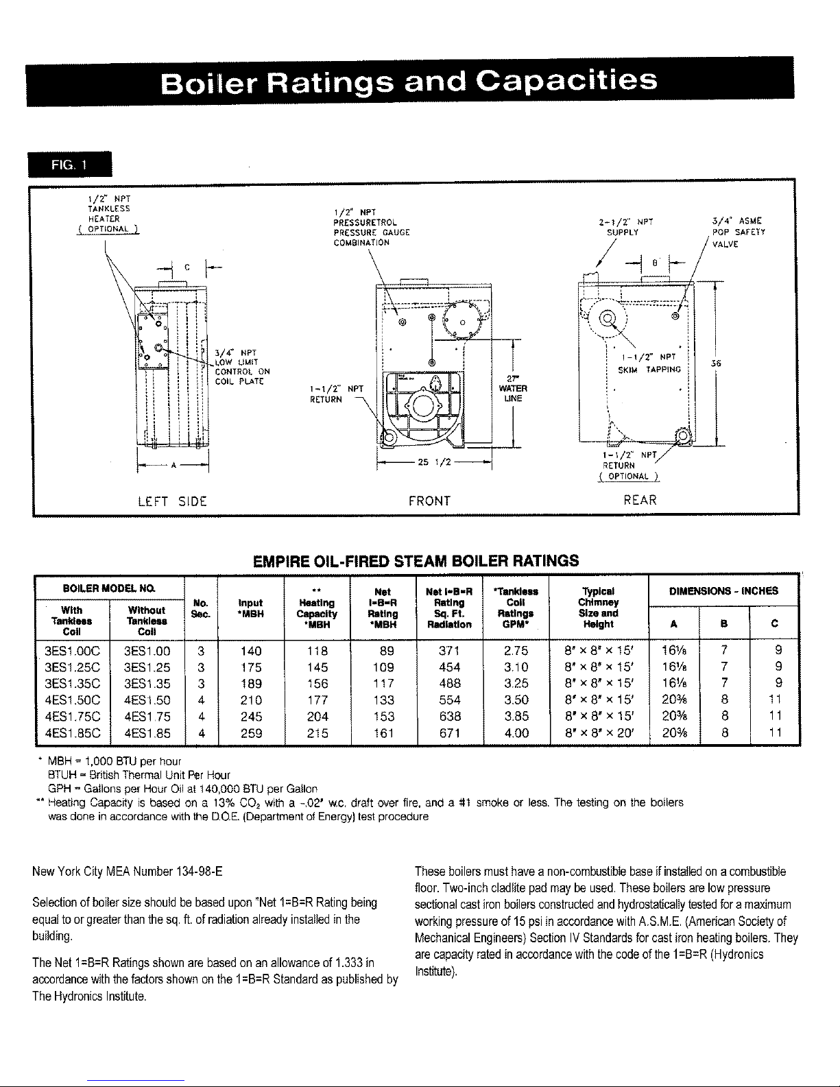
EMPIRE OIL-FIRED STEAM BOILER RATINGS
BOILER MODEL NO.
With Without
Tankless Tankless
Coil Cotl
3ESt O0C 3ES100 3
3ES1.25C 3ES1,25 3
3ES1.35C 3ES1.35 3
4ES1,50C 4ES1,50 4
4ES1.75C 4ES1 75 4
4ES1.85C 4ES1.85 4
* MBH = 1,000 BTUpet hour
No.
9ec.
Input
*MBH
140
175
189
2!0
245
259
Nesting
Capacity
*MBH
118
145
156
177
204
215
Net
I=B-R
Rating
"MBH
89
109
117
133
153
161
Not I-S-R
Rating
Sq. Ft,
Radiation
371
454
488
554
638
671
*Tonldelm
Cell
Ratings
GPM*
2.75
3,10
3.25
3.50
3.85
4,00
Typl©al
Chimney
Size and
Height
8" x 8' x 15'
8" x 8' x 15'
8" x 8' x 15'
8' x 8' x 15'
8" x 8" x 15'
8" x 8' x 20'
CIMF31SIONS- INCHES
A B C
16% 7 9
16½ 7 9
16% 7 9
20% 8 11
20% 8 11
20% 8 11
BTUH = British Thermal Unit Per Hour
GPH _ Gallons per Hour Oil at 140,000 BTU per Gallon
** Heating Capacity is based on a 13% CO2 with a -,02' w.c, draft over fire, and a #1 smoke or less. The testing on the boilers
was done in accordance with lhe DOE. (Department of Energy) test procedure
NewYorkCityMEANumber134-98-E
Selectionofboilersizeshouldbe basedupon"Net1=8=RRatingbeing
equaltoorgreaterthanthesq.ft.of radiationalreadyinstalledinthe
building.
TheNetI=B=R Ratingsshownarebasedonanallowanceof1.333in
accordancewiththefactorsshownonthe 1=B=RStandardas publishedby
TheHydronicsInstitute.
Theseboilersmusthavea non-combustiblebaseifinstalledon acombustible
floor.Two-inchcladlitepadmaybeused.Theseboilersarelowpressure
sectionalcastironboilersconstructedandhydrostaticallytestedfora maximum
workingpressureof 15psiin accordancewithA.SME. (AmericanSocietyof
MechanicalEngineers)SectionIVStandardsfor castironheatingboilers.They
arecapacityratedinaccordancewiththecodeofthe1=B=R(Hydronics
Institute).
Page 3
RulesforSafeInstallationandOperation
1. Readthe Owner'sManualforSafeOperationcarefully.Failuretofollow
therulesforsafeoperationandtheinstructionscancausea malfunctionof
the boilerand result in death,_rious bodily injury, and/or property
damage.
2. Checkyourlocalcodesandutilityrequirementsbeforeinstallation.The
installationmustbeinaccordancewiththeirdirectives,orfollowNFPA31
- InstallationofOilBurningEquipment,latestrevision.
3. Beforeservicing,allowboilertocool.Nwaysshutoffanyelectricityand
oiltoboilerwhenworkingonit.Thiswillpreventanyelectricalshocksor
burns.
4. Inspectoillineandconnectionsforleaks.
5. Be certainoil burnernozzleis size required.Overfiringwill resultin
earlyfailureofthe boilersections.Thiswill causedangerousoperation.
6. Nevervent this boiler into an enclosedspace.Alwaysvent to the
outside.Neverventto anotherroomor insidea building.
7. Besurethereisadequateairsupplyforcompletecombustion.
8. Followa regutarserviceandmaintenancescheduleforefficientand
safeoperation.
9. Keepboilerareacleanandfreeofcombustiblematerial,gasolineand
otherflammablevaporsandliquids.
This boiler has been designed for residentialinstallations. If used for commercial
applications,alljurisdictionalrequirementsmustbe met.This mayrequirewiringandlor
pipingmodifications.Themanufactureris notresponsibleforany changesto the original
design.
BeforeYouStart
Check to be sure you have the dght size boiler beforestartingthe
installation.See ratingand capacitytableon precedingpage.Checkthe
ratingplateontheboiler.
You mustsee that theboileris suppliedwiththe properoil,freshair for
combustion,and a suitableelectricalsupply.Also, the boiler must be
connectedto a suitableventingsystemand an adequatepipingsystem.
Finally,a thermostat,properlylocated,is neededforcontrolofthe heating
system.If youhaveanydoubtsas to thevariousrequirements,checkwith
local authorities and obtain professionalhelp where needed. THE
OPERATING INSTRUCTIONSand THE FINAL CHECKS AND
ADJUSTMENTSare vitalto the properandsafe operationof the heating
system.Takethetimeto besuretheyarealldone.
Thefollowingstepsareallnecessaryforproperinstallationandsafe
operationof yourboiler.
1. LOCATINGTHEBOILER
2. OILSUPPLYANDPIPING
3. FRESHAIR FORCOMBUSTION
4. PIPINGCONNECTIONS
5. CHIMNEY& VENTPIPECONNECTIONS
6. ELECTRICALWIRING
7. THERMOSTATLOCATION
8. CHECKING&ADJUSTING
9. MAINTENANCE
Page 4
Locatingthe Boiler
If yourboileris partof a plannedheatingsystem,locateit as nearlyas
possiblewhereshownon yourplan.If boileris to be partof an existing
system,it is usuallybestto put it wherethe old onewas.If youplanto
changelocation,youwill needadditionalmaterialsaswellasan adequate
base.Thefollowingrulesapply:
1. The boilermustbelevelandlocatednearpiping.
2. Usea raisedbaseiff]oorcanbecomewetordamp.
3. Theventpipeconnectionshouldbeas shortaspossible.
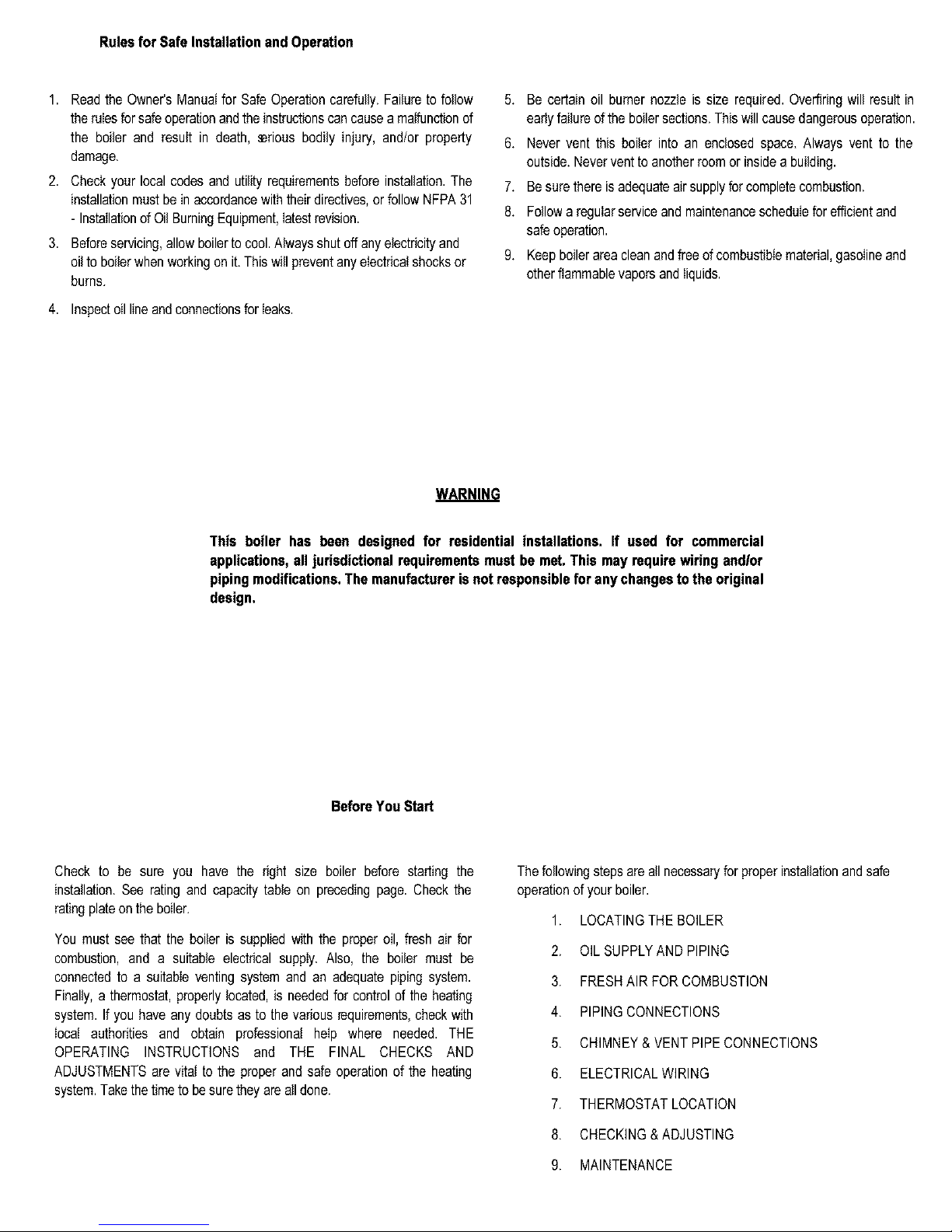
4. Maintainclearancesforfiresafetyaswellasservicing.SeeFigure2for
minimumclearances.18"clearancemustbemaintainedatasidewhere
passageisrequiredforaccessto anothersidefor cleaning,servicing,
inspection,or replacementofanypartsthatnormallymayrequiresuch
attention.Boilersmustbe installedat least6"fromcombustiblematerial
onallsidesandabove.Allowat least24"frontclearancefor servicing.
Allowat least18"leftsideclearanceforservicingboilersequippedwith
atanklesscoil.
5. FRESHAIRfor combustionmustbeavailableatthefrontoftheboiler.
FRESHAIRfor ventilationmustbeavailabletothefrontANDrearof
theboiler.Airpassagesmustbefreeofobstructionsatalltimes.
Ventilatingandcombustionairmustenterboilerroomwithout
restrictions.
6. The floor suppo_ng the boiler must be non-combustible.If it is
combustible,placetheboileron 2" cladlitepad.Thepadmustbeunder
theentireboilertoprotectthefloor.
7. Besureinstallationisinaccordancewiththerequirementsofthelocal
authoritieshavingjurisdiction.Compliancewiththeseregulationsis
required.In theabsenceof localcodes,followNFPA31- Insbtlationof
OilBurningEquipment.
Q 6" MIN. 18" WITH COIL
• _
_" 6" MIN. "
I_// . I BOILER
I-----2, .,..------IFRO.T
6" MIN.
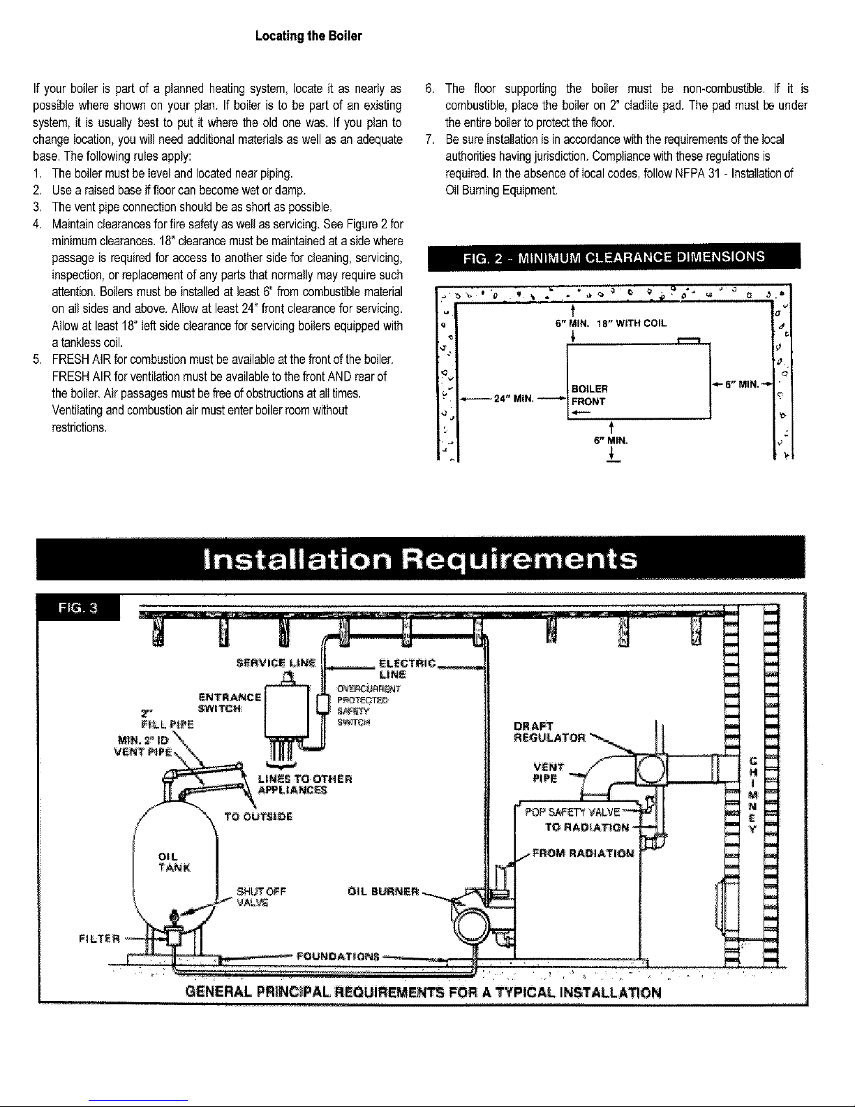
SeRVraceL_NeLL,.------e_.ec_rRic
F_LPtFE ] I I[ s_,rrc_
GENERAL PRINCIPAL REQUiREMEnTS FOR A TYPICAL INSTALLATION
m_
Page 5
Fresh Air for Combustion
WARNING
NOTE
Be sure to provide enough fresh airfor combustion. Enough air ensures
proper combustion and assures that no hazard will develop due to
the lackof oxygen.
If you use a fireplaceor a kitchenor bathroomexhaustfan,you
shouldinstallan outsideairintake.Thesedeviceswill robthe boiler
andwaterheaterof combustionair.
You must providefor enough fresh air to assurepropercombustion.The fire
in the boiler uses oxygen. It must have a continuous supply. The air in a
house contains only enough oxygen to supply the burner for a short time.
Outside air mustenter the house to replace that used by the burner. Study
foIIowingexampIes 1 and 2to determineyour fresh air requirements.
EXAMPLE 1:Boiler Located in Unconfined Space
If your boiler is in an open area (unpartitioned basement) ina conventional
house, the air that leaks through the cracks around doors and windows will
usually be adequate to provide air for combustion. The doors should not fit
tightly. Do not caulkthecracks aroundthe windows.
An unconfinedspace isdefined as aspace whose volume isnot lessthan 50
cubic feet per 1,000Btu per hour of the total inputrating of all appliances
installedin that space.
EXAMPLE 2: Boiler Located in Confined Space
A, All Air from Inside the Building: The confined space shall be provided
with two permanent openings communicating directly with an additional
room(s) of sufficientvolume so that the combined volume of all spaces
meets the criteria for an unconfined space. The total input of all
combustion equipment installed in the combined space shall be
considered in making this determination. Each opening shall have a
minimumfree area of one square inch per 1,000Btu per hourof thetotal
inputratingofall combustionequipment inthe confinedspace, but not less
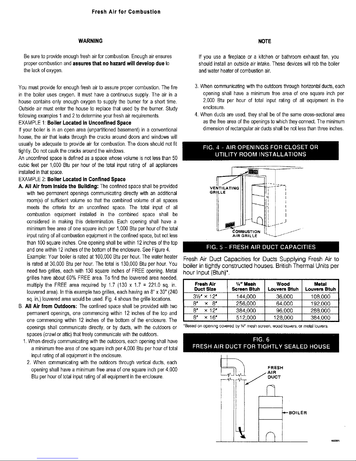
than 100 squareinches. One opening shall be within 12 inches ofthe top
andonewithin 12 inchesof the bottom of theenclosure.See Figure 4.
Example: Your boiler is rated at 100,000 Btu per hour. The water heater
is rated at 30,000 Btu per hour. The total is 130,000 Btu per hour. You
need two grilles, each with 130 square inchesof FREE opening. Metal
grilles have about 60% FREE area. To find the Iouveredarea needed,
multiply the FREE area required by 1.7 (130 x 1.7 = 221.0 sq. in.
Iouvered area). In thisexample twogrilles, each having an 8"x 30" (240
sq.in,) Iouvered area would be used. Fig. 4 shows the grille locations.
B. All Air from Outdoors: The confined space shall be provided with two
permanent openings, one commencing within 12 inches of the top and
one commencing within 12 inches of the bottom of the enclosure. The
openings shall communicate directly, or by ducts, with the outdoors or
spaces (crawlor attic)thatfreely communicatewith the outdoors.
1.When directly communicatingwith the outdoors, each opening shallhave
a minimum free area of one squareinchper 4,000 Btu per hour of total
inputratingof all equipment in theenclosure.
2. When communicatingwith the outdoors through ve_cal ducts, each
opening shall have a minimumfree areaof one square inch per 4,000
Btu perhour of total input ratingof all equipmentin theenclosure.
3.Whencommunicatingwiththeoutdoorsthroughhorizontalducts,each
openingshall havea minimumfreearea of onesquareinchper
2,000 Btu per hour of totalinput ratingof all equipmentin the
enclosure.
4. Whenductsareused,theyshallbeof thesamecross-sectionalarea
asthe freeareaof theopeningstowhichtheyconnect.Theminimum
dimensionofrectangularairductsshal{benotlessthanthreeinches.
VENTILATING -'_--i
GRII.LE I
i I ' 1
i ,11 II ',
AIR GRILLE _
Fresh Air Duct Capacities for Ducts Supplying Fresh Air to
boiler in tightly constructed houses. British Thermal Units per
hour Input (Btuh)*.
Fresh Air
Duct Size
31/2"x 12"
8* x 8"
8" x 12"
8" x 16"
1/4"Mesh
Screen Btuh
144,000
256,000
384,000
512,0O0
Wood
Louvers Stuh
36,000
64,000
96,000
128,000
Metal
Louvers Btuh
108,000
!92,000
288,000
384,000
*Based on opening covered by IA" mesh screen, wood louvers, or mela{ louvers
FRESH
Page 6
Boilers With Tankless Heater Coil
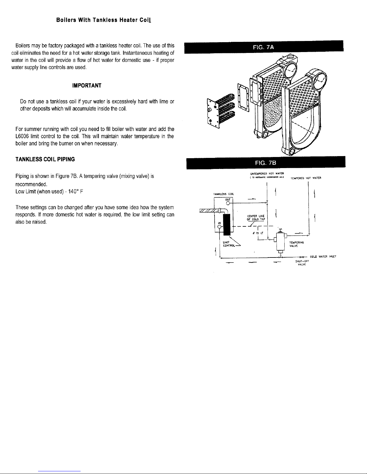
Boilersmaybefactorypackagedwithatanklessheatercoil.Theuseof this
coileliminatesthe needforahot waterstoragetank.Instantaneousheatingof
waterinthecoil willprovidea flowof hotwaterfor domesticuse- ifproper
watersupplylinecontrolsareused.
IMPORTANT
Donot usea tanklesscoilif yourwateris excessivelyhardwithlimeor
otherdepositswhichwillaccumulateinsidethecoil.
Forsummerrunningwithcoilyou needtofill boilerwithwaterandaddthe
L6006limitcontrolto the coil.Thiswill maintainwatertemperaturein the
boilerand bringtheburneronwhennecessary.
TANKLESSCOlL PIPING
PipingisshowninFigure7B.A temperingvalve(mixingvalve)is
recommended.
LowLimit(whenused)- 140° F
Thesesettingscanbechangedafteryouhavesomeideahowthe system
responds.If moredomestichotwateris required,the lowlimitsettingcan
alsoberaised.
_NT_pERE_ _OT WATER
¢OL_ WATE_ _N_ET
WLV_
Page 7

Installation-SystemPiping
Thenearboilerpiping,thatisthe pipingaroundtheboiler,mustbeconsidered
aspartofthe boilerforproperwaterlevelcontrol,andto producedrysteam.
Correctnearboilerpipingis crucialtothe properoperationoftheboilerand
theheatingsystem.Followtheserecommendationscarefully.
1.Placeboilerintheselectedlocation,as nearchimneyaspossible.
2. Installthepopsafetyvalve,usingthefurnished3/a" 90" ell,intothe3/4"
pipenippleonthebackof theboiler.Makea dischargepipe,using3/4"pipe
(notfurnished)to carrythe wateror steamto a nearbydrain.Do not
connectthe dischargepipe directlyto a drain but leavean airgap.No
shutoffofany descriptionshallbeplacedbetweenthe popsafetyvalveand
theboiler,or ondischargepipes
betweensuchsafetyvalvesandthe atmosphere.Installationof thepop
safetyvalveshallconformtotherequirementsoftheANSI/ASMEBoiler
and Pressure Vessel Code, Section IV The manufactureris not
responsibleforanywaterdamage.
3.Thisboileris equippedwithtwo 21/2"supplyconnectionson topand
two 1V2"returnconnections,oneeachon frontand backsidesof the
boiler.Unusedconnectionsmust
4.Recommendednearboilerpipingfor gravityreturnsys-temsisshown
in Figure8. Thisconfigurationusesonesupplyandonereturntapping.
Pipingoff bothboilertap-pingsis recommendedon units5 sectionand
larger.
Note:Usebothsupplytappingsonboilers5 sectionandlarger.
PtPES_E
Page 8

5.Forinstailerschoosingto usebothsupplytappings,Figure8Ashowsthe
correctwayto pipethissystem.Figure8Bshowsthewrongwaytopipe
a headerwithtworisers.
, Headersmustbe fittedwithheaderoffsetsor swingjoints, or be
equippedwith expansionjoints, so that thermalexpansionand
contractionofthe headerwillnat damagetheboiler.Headersshall
netbewelded.
, Systemtakeoffsfromtheheadermustbebetweentheequalizerand
therisertothe headernearesttheequalizer.Systemtakeoffsmust
neverbebetweentworisers.
6.Systemtakeoffsfromtheheadermustneverbe bull-headed.Ifthesteam
maingoesintwodirections,theremustbetwotakeoffsfromtheheader,
oneforeachmain.
7. All boilersingravityreturnsystemsmustbeequippedwitha Hartford
LoopasshowninFigures8and8A.
8. Whenpipingtheverticalrisersfromtheboilertotheheader,thebottom
ofthe headermustbea minimumof 24inchesabovethewaterlevel
lineantherightsideoftheboiler(i.e.51inchesabovethefloor).
9. Steamriser(s)andheadershallbe272"pipesize.
10. Equalizerlineshailbeminimum1 1/2"pipesize.
11. The boilerhasa 1V2"tappinginrearsecflanfarskimming.
_EA_{ MAINS
HART_ORO
CLOSE
N|PPLE
MAIN VENT
D_Y RETURN
M_[N
Page 9

THIS, PIPING
COMMON
tS INCORRECT
MISTAKES
TO SHOW
©
L
12. The near boilerpipingshall includea 1 1/2"ballvalveinthereturn
pipingasshowninFigure8Afarbottomblowdawnanddraining.
13. Forgravityreturnsystems,thebottomof theloweststeamcarrying
pipe,beita dryreturn,ortheendofthesteammain,mustbeatleast
28"abovethenormalwaterlevellineanthedghtsideoftheboiler.
Thisisknownas"DimensionA."
14. Forpumpedreturnsystems,followthecondensatepumporbailerfeed
pumpmanufacturer'sinstructionsforproperinstallationandhookup.
15. Inconnectingthecoldwarer supplytothewaterinletvalve,makesure
thata deanwatersupplyisavailable.Whenthewatersupplyis froma
wellor pump,asandstrainershouldbeinstalledatthepump.
FORUSEWITHCOOLINGUNITS
A.
This boiler, when used in connection with chilledwater systems,must
be installed so that the chilled water is piped in parallel with the heating
boiler. Appropriate valves must be used to prevent the chilled water
from enteringthe heating boiler(Fig. g).
B.Whenthis boileris connectedto heatingcoilslocatedin air handlingunit.,
wherethey may be exposedto refrigeratedaircirculation,the piping
systemshall be equippedwith flow controlvalves or other automatic
meansto preventgravitycirculationof theboilerwaterduringthecoolinc
cycle.
'_rd,.vE8 A & m
VALVESC & Q
_R _OUNG
Page 10

ChimneyandChimneyConnection
CHECKYOURCHIMNEY
Followlocalcodes.Inthe absenceof localcodes,followANSI/NFPA31
Installationof OilBurningEquipment,latestedition.
Thisisaveryimportantpartof yourheatingsystem.Noboiler,however
efficientitsdesign,canperformsatisfactorilyifthechimneythatservesitis
inadequate.Checkyourchimneytomakecertainthatit isthe rightsize,
properlyconstructedandinsoundcondition.
Itischeapertorebuildapoorchimneythanto payexcessivefuelbills.If
yoursisanoldmasonrychimney,a newsteellineror anew
prefabricatedchimneymaybethebestsolution.Thefollowingchartshows
recommendedminimumchimneysizesbasedonTable3andFigure6 of
theI:B:R TestingandRatingStandardfor HeatingBoilers,Sixth
Edition,June1989.
MUST BE REQUIRED MIN*
IMUM HEIGHT, MUST BE
AT LEAST 3 FT. HIGHER
THAN HIGHEST PART OF
PASSAGE THROUGH
ROOF. MUST BE AT
LEAST 2 FT. HIGHER
THAN ANY NEIGHBORING
OBJECT. MUST HAVE AN
UNOBSTRUCTED TOP
OPENING,
MUST BE AT LEAST
4 INCHES THICK -
AND BE LINED.
_l_ CHFM_ I
.60- i 30 15
13Iol 80 15
i,81o2,00 20
FIECOMMENDED MtNiMUM _IMNEY SIZES
=!:
_ER_ LNER;
_!NNqY' i_DE I_
8"×8 ' 6' 6:5_x 6_'
8' x 8" 7' , 6_f;_"× 6_!4"
[:<]re#_@:(Y)88_ee 2,#_ if,,8J3_es_ _i, ad_3 feetIocblm_qeYhe_gP4_
[_!et la Fiqure 1@t
Foradditionalchimneydesignandsizinginformation,consulttheASHRAE
1996HVACSystemsandApplicationsHand-book,Chapter30,Chimney,
GasVentandFireplaceSystems;ortheNationalStandardforChimneys,
Fireplaces,VentsandSolidFuelBurningAppliances,ANSI/NFPA211.
CHIMNEYCONNECTORANDDRAFTREGULATOR
Yourboilerrequires7"diameterchimneyconnectorpipeon 3 section,8"
diameterchimneyconnectorpipeon 4 section.Youmustalsouse a dralt
regulatorpackedwithboiler.Properlyinstalled,theregulatorwillcontrolthe
draftautomatically.Itis bettertoinstallitina horizontalsectionofthe pipe;but
itmaybeinanangledorverticalsection.Justmakecertainthatthe"top"isat
top- andthattheshortpipesectionwhichholdstheVaneishorizontal.Install
itascloseaspracticableto theboiler.
Toinstallthechimneyconnector,startatthe boilerandpreferablytakeoff
fromthefluecollectorcollarwithanelbow- theninstallthedraftregulator
next,makingit horizontal.Whentheregulatoris inplace,startatthechimney
andworkbacktotheregulator.JointhetwosectionswithaDrawband.The
horizontalpipemustslopeuptowardthechimneyatleast1/4inchperfoot.It
mustnotleakandmustbefirmlysupported.Joinsectionswithatleasttwo
sheet-metalscrews.Supporteverysecondsectionwithastovepipewire.
MINIMUMVENTPIPECLEARANCE
ALTERNATE POSITIONS
TOP
1
MUSTSLOPEUP
AT LEAST 1/
PER FOOT OF
HORIZONTALRUN
DRAWBAND
LAST PIECE
INSTALLED
I
I L
_,TIGHT. SMOOTH,
CORRECTLY SIZED.
I
I
t
I
&LEDIN
THIMBLE
TIGHT
DOOR
DRAFT REGULATOR
VANE
Woodandothercombustiblematerialsmustnotbecloserthan18"fromany BALANCEDWEIGHT
surfaceoftheventpipe.
Page 11

EquipmentandOptionalAccessories-WhatTheyDo
POPSAFETYVALVE
Youmusthavea popsafetyvalveonyourboiler.Steamexpandsasit isheated.
Ifthereisno placeforthesteamtoexpandinto,pressurewillbuildupinsidethe
boilerandsystem.Shouldthishappen,the popsafetyvalvewillautomatically
openata pre-determinedpressure.Thiswill relievethestrainontheboilerand
system.Runapipefromthesafetyvalveoutlet(pipemustbesamesizeasoutlet
andtheopenendmustnotbethreaded)toan opendrain,tuborsink,or other
suitabledrainagepointnotsubjecttofreezing.Failuretodosomaycausewater
damageorinjuryshouldreliefvalverelease.Do notcapoffthedrainlinefrom
thisvalve!Eachpopsafetyvalveisprovidedwitha liftingdevicefortestingand
shouldbetestedmonthlyduringtheheatingseason.Refertosafetyvalve
manufacturer'sinstructionspackagedwithsafetyvalve.
STEAMPRESSUREGAUGE
Everysystemshouldhaveapressuregaugeinstalledintheboiler.Thisgauge
enablesyoutomonitorthe pressureinthesystem.Ifthesafetydevicesfailtoshut
offyourboileratthepropersettings,notifyyourservicetechnicianimmediately
WATERLEVELGAUGE
Thewaterlevelin theboilercanbeseenthroughtheglasstubeinthewater
levelgaugeatsideof boiler.Correctcoldboilerwaterlevelisstampedonside
jacketpanel.Whenmakingsteam,thewaterlevelwilldroponetothreeinches.
Thewaterlevelshouldbecheckedregularly.
STEAMPRESSURECONTROL
Thesteampressurelimitcontrol(pressuretrol)shutsofftheoiltotheburnerifthe
steampressureintheboilerreachesthecut-offsetpoint(i.e.thesumofthecut-in
andthedifferentialsetpoints).Burnerretireswhenthesteampressuredropsto
thecut-insetpoint.Systempressurerequirementsarebasedonthesizeand
conditionofthepipes,andtheload.
Forgoodsystemoperation,thecut-insettingofthe pressuretrolshouldnever
be less than twicethe systempressuredrop. In a typicalsinglefamily
residencewith a cleanonepipeheatingsystemandcastiron radiation,this
meansthatthecut-inwillusuallybesetattheminimumsetting,i.e._/2psi.
Steamradiationis usuallysizedbasedon squarefeet of equivalentdirect
radiation(EDR).Thisis basedon a steampressureintheradiatorofjust less
than1 psi.Therefore,in our examplesystemfromabove,wewouldsetthe
differentialadjustmentat1psi,i.e.thesteampressurerequiredinthe radiators.
Thiswillgiveusa cut-offsetpointd 1_12psi.
Theaboveisan exampleofa typicalonepipesystem.Forlargersystemsor
othertypesofsystemssuchas two pipesystems,orsystemswithconvectors
or fan coil units,the pressuretrolsettingswill needto be determinedon a
system-by-systembasis.
The cut-insetpointisdeterminedbythesystempressuredroptothe furthest
radiatoror terminalunit.Doublethesystempressuredropasa safetyfactor,
resultinginthe rulethatthe cut-insettingshouldneverbe lessthantwicethe
systempressuredrop.
Thedifferentialset#ointis thesteampressurerequiredattheterminalheating
units.
Nowyourboilerwill operateinthe correctpressurerange.It will maintain
enoughsteampressureto sendthe steamouttothe furthestradiator,andnot
go overtheoptimumsteampressurethatisrequiredat theradiators.
67D-t LOWWATERCUT-OFF
Thefloat-typelowwatercut-offshutsofftheburnerwhenthewaterlevelis
belowasafepoint.Theburnerwillstartwhenthewaterisrefilledtoa
minimumsafelevel.
WATERFEEDER(Optional)
Awaterfeederworkswiththelowwatercut-off(LWCO)tomaintaina
minimumsafelevelofwaterforboileroperation.It'susedtokeeptheboiler
runningbycompensatingforminorevaporativesteamleaks,andtoprevent
freeze-upsif thehomeownersareawayanda returnlineshouldspringa
leak,Theautomaticwaterfeederisa safetydevice,nota
convenienceitem.Itisnotdesignedto maintaina "normal"waterline.The
waterfeederdoesnottaketheplaceofa responsiblepersonmonitoringand
maintainingthe"normal"waterline.Steamboilersrequirepersonal
attention.
Four electric water feedersare offeredby McDonnell-Millerwhichare
compatiblewiththe 67D-1LWCO.The model#101Aand #WF2-U-120
waterfeedersareusedwith120voltwiringcircuits,asfoundanthissteam
boiler.The McDonnell-Millermodel#101A-24and#WF2-U-24areused
with 24 volt circuits,whichmay be usefulin a retrofitinstallationwhich
alreadyhasa 120voltto 24volttransformer.
TheWF2-U-120and WF2-U-24(Uni-Match)waterfeedersareequipped
witha solidstateelectroniccontrolwhichfeedswaterwhensignaledbythe
LWCO.Thewaterfeedrate isfieldadaptablefar 1,2, or 4 gpm.These
waterfeedershavean adjustableslideswitchtomatchthetimingcyclean
theLWCO.Whenusinga McDonnell-MillerLWCOtheslideswitchneeds
toselectposition#1.The timingcyclecreatesaninitialdwellperiodofone
minuteto allowcondensateto be returnedto the boiler.If afterthedwell
periodthewaterhasnatreachedtheminimumsafelevelandcompletedthe
LWCOcircuit,thenwateris fedat theselectedflowratefaroneminute.The
dwellpedodistheninitiatedagainfar oneminute.Ifthewaterlevelhasstill
not reachedthe minimumsafe level,then wateris addedagain at the
selectedflowrateforoneminute.Thiscyclecontinuesuntilwaterreaches
the minimumsafe levelandthe circuitis completed.DunkirkRadiator
recommendsusingaUni-Matchwaterfeederataflawrateof1or2gpm.If
the steamboilerrequireshigherflowrateson a regularbasisa service
technicianshouldbenotified.
The1OlAwaterfeedermaybe used,howeverthewaterfeed rateistoo
high and needsto be regulatedor throttled.The IO1Awillfeedupto 6
gpm,muchgreaterthanthedesiredflowrateof 1-2gpm.Also,thereisno
dwellperiodto providea marginfor condensateto returnto the boiler.
Thesetwofactorsincreasethechancesofoverfeedingwaterto thesteam
boiler.Excessivewaterinthesteamboilerwillproducenoise
Consultthe water feedermanufacturer'sinstallationguidelinesfor more
detailson waterfeederselection,recommendedpipingarrangement,and
start up procedures. Dunkirk Radiator supports McDonnell-Miller's
recommendationtoarrangetheinstalledpipingsoa brokenuniontest can
beimplemented.
DRAINVALVE
Thismanualvalveprovidesa meansofdrainingallwaterfromtheboilerand
system.Itshouldbeinstalledinthe3/a"teewherethewatersupplyline
enterstheboiler(Fig.8).Youcanalsousethisvalveto lowerthewaterlevel
ifit istoo high.
Page 12

STEAMVENTS
Beforea steamsystemwill operateproperly,suitablesteamventsmustbe
installedin eachradiatoras wellasthe returnmain.Somesystemsrequire
steamtrapsinthereturnlineat theradiationunit.
The"Hartfordloop"isa pipingarrangementwhichmustbeincluded(Fig.8)
forproperoperationofthesteamsystem.
BOILERSWITHTANKLESSCOILSONLYFlowRegulatorandWater
TemperingValve
Ifyouhavea TanklessCoilfordomestichotwater,thesetwopartscanbe
used.Thiswillprovideyouinstantaneoushotwaterthatis neither
scaldinghotnormerelytepid.The FlowRegulatorisplacedinthecoldwater
linetothecoil.It assuresa steadyflowofwatersothatthecoilcanproperly
heatit. It prevents"spurts"of "half-heated"water.Thisisimportantwherethe
waterpressureisexcessivelyhighorvariable.TheWaterTemperingValve
is atee whichis connectedata junctionbetweenthehotwaterlinefromthe
coilandacoldwaterbranchfromthesupplyline.Itmixeshotandcoldwater
as requiredto furnisha temperedsupplyof watertothe house.Thewater
willbejustthe righttemperatureforyouruse.Thisisimportanton a steam
systemto preventscaldingtemperaturesat thefaucets.Bothpartsareself-
containedandautomatic.
Starting Your Boiler
HOWASTEAMSYSTEMOPERATES
Thewaterintheboilerisheateduntilit reachestheboilingpoint.Asthe
waterboilsit turnsintosteam.Thesteamrisesfromthetopof thewater
throughthesupplymainto theradiationunits.As it passesthroughthe
radiatorsitreleasesitsheatandcondensesintowater.Thewaterreturns
tothe boilerthroughthe returnmain.
FILLINGSYSTEMWITHWATER
Onsteamheatingsystemstheboileris partiallyfilledwithwater.Itisvery
importantto theproperoperationoftheentiresystemthatyourboilerbe
filledto theproperlevel.Thecorrectwaterlevelon coldstartconditionis
abouthalfwayupthe glasswaterlevelgaugeasmarkedon theboiler
jacket.Tofill:
1.Closetheboilerdrainvalve.
2. Openthevalvesat thetopandbottomoftheglasswaterlevelgauge.
Alsoopenthedrainvalveatthe bottomofthegauge.
3. OpenthefilIvalveandatlowwatertorunintotheboiler.
WARNING- Neverrunwater intoahotemptyboiler,
4.Allowboilertofill untilwaterrunsoutthe gaugedrainvalve.Then
closethegaugedrainvalve.
5.Continuetofillboileruntilwaterreachestheindicatedwaterline.This
Checking and Adjusting
isabouthalfwayuptheglasstube.Alwayskeepthewateratthislevel
whensystemisoff.
IMPORTANT
Skimminga newsteamboileronan existingsystemmustbedoneseveral
timesto removeall oil,greaseandsediment.Thereshouldbe a teewitha
plugpipedtothesupplylineoftheboilerinordertoproperlyskimtheboiler.
Wheneverthewaterin the glassgaugebecomesdiscolored,yourboiler
shouldbeskimmed.
Whenskimming,makesureto pipetheopenendof thetee tothefloorora
drainto preventanyonefrom beingburnedbythe steamand hotwater
whichwillbereleased.
TheFloatLowWaterCut-offshouldbe blowndownafterskimming.Following
blowdown,allowtheboilertocoolandthenaddfreshwaterslowly.
Thefloatchamberof thelowwatercut-offmustbeflushedcleanandmaintained
clearof sedimentto allowfree movementof the float.This mustbe done
frequentlyduring initial operationof the boilerand at least once per week
thereafter.Followinstructionsontagattachedto control.Neverthrottlea steam
radiatorvalve on a one-pipesystem.It mustbe fully openor fully closed.
Otherwisewaterisheldintheradiatorunits.Thiswillcauseknockingsounds.
Skimmingmayberequiredagainafterafewdaysoperation.
CHECKINGCONTROLS
To checkthe LowWaterCut-Off,turnoff powerto theboileror turnthe
thermostatdown to the lowestsetting.Drainwaterto belowthe visible
bottomof thewatergaugeglass.Turnpoweronandturnthe thermostatto
callfor heat.Whenthe boilerisequippedwiththefloattypeLWCO,theoil
burnershouldnotrunonacallfor heatwhenthewaterislow.
To check the pressurelimit, run the boileruntil the pressurereaches
systemdemand.Thenturn the pressurescrewanddropthe pressure
settinguntiltheboilershutsdown.Thiswillshowthatthe pressurelimitis
operatingproperly.
If youhaveinstalledyourown boiler,we recommendthat youcallfor an
inspectionby a servicetechnician.The peace of mind and assured
performanceare wellworththe cost involved.Hecanquicklymakethe
necessarychecksandadjustments.
OIL BURNERADJUSTMENT
Suggestednozzlesandpreliminaryburnersettingsarefoundon page20.
Referto youroil burnerownersmanualfor checkingandadjustingthe
burner.
ADJUSTOPERATINGCONTROLSInstructionsfor eachcontroland
burnerareincluded.
Betthermostatheatanticipatorat.20.Instrucfionsforthefinaladjustmentof
thethermostatarepackagedwiththethermostat.
CHECKTHERMOSTATOPERATION
Whensetabovetemperatureindicatedon the thermometer,boilerburner
shouldstart. Makecertainthe thermostatturnsoff the boilerwhenroom
temperaturereachesthe selectedsettingand startsthe boileroperating
whenroomtemperaturefallsafewdegrees.
Finally,setthethermostatforthedesiredtemperature.Specialconditionsin
yourhomeandthelocationofthethermostatwillgovernthissetting.
Page 13

MaintainingYourBoiler
Checkthe waterleveleverydayor two.Verifythe watertineshownby
operatingthe drainvalvean thegauge.Be suretop and bottom valves
on gaugeare alwaysopen so thatactualwater levelwill be shown
atalltimes,
POPSAFETYVALVE
Thisvalveshouldopenautomaticallywhenthesteampressureexceedsthe
safelimit(perinstructionspackagedwithvalve).Shoulditeverfailto open
undertheseconditions,shut downyoursystem.Havethevalvereplaced
immediately,The pop safetyvalve shouldbe testedmonthlyduringthe
heatingseason.Refertothevalvemanufactureflsinstructionspackagedwith
thepopsafetyvalve.
LOWWATERCUT-OFF
TheLowWaterCut-offwillin_rrupttheelectricalcurrenttotheburnerwhen
thewaterlinein the boilerdropsto a low level.It isveryimportanttokeep
thefloatchamberfreefromsediment,a conditionessentialto dependability.
To keep any accumulationfrom interferingwith floatactionis to "BLOW
DOWN"or flushoutthecontrolregularly.Thismustbedonetwo-threetimes
thefirstweekafterinstallationandonceaweekthereafterduringtheheating
season.Doitwhiletheboileris inoperation.Firstnotewaterlevelingauge
glass.Openblow-offvalveatbottomof control,waterwillpourout,flushing
awaysediment.Drainuntilwaterisclear,abouta pail,thenclosevalve.If
waterlevelingaugeglasshasdropped,addwaterto boilertorestorelevel.
Consultlow water cut-offmanufacturersinstructionsincludedwithboiler.
NOTE:Openingblow-offvalvecheckscut-offoperationtoo.As floatdrops
withfallingwaterlevel,burnerswillshutoff.Aftervalveisclosedandnormal
operatingconditionsarerestored,burnerswillresumefiring.
Boilersshouldnot be drainedbetweenheatingseasons.Onlywhenthe
waterin thesystembecomesdirtyshouldtheboilerbe drained,flushedor
boiledout,andrefilled.Steamboilersmaybeentirelyfilledwithwaterduring
thesummermonthsto excludeair.
CLEANINGYOURBOILER
Undernormaloperatingconditions,withthe burnersproperlyadjusted,we
recommendthat you have the flue passages,burneradjustment,and
operationof the controlschecked once each year by a Service
Technician.
Before the start of each season (orwheneversystemhasbeen
shutdownforsometime)recheckthe wholesystemforleaks...andrecheck
theboilerandventpipefor leaks.Replaceor patchanyboilersealsthatare
faulty.
BOILERFLUEPASSAGES
FluePassagesbetweensectionsshouldbeexaminedyearlyandcleaned.
Removevent pipe.Raisetoppanelof boilerandswingoutto exposeflue
collector.Removefluecollectortop. Cleanpassagewaysbetweensections
witha flexiblehandlewirebrush.Removedirtfomthebottomoftheboiler
and reassembleall parts.Be sureventpipeconnectionsto chimneyare
secureandnoobstructionsarepresent.
FOAMING,PRIMINGORSURGING
Thesetermsareusedtodescribeafluctuatingwaterline- whenwater
leavestheboiler.
Itiscausedby anycombinationofthefollowing:
1.Threadingoilandorganicmatterintheboilerwater.(Mineraloil, orcore
sanddoesnotcausesurging.)
2. Faultyquickventsthatdonot releaseairuntila sizeablepressureisbuilt
up- replace.Ifdirty,cleansothatyoucaneasilyblowthroughvalve.
3. Improperheader design - whensteamflowsinoppositedirectionof
equalizerlineon"Hartfordloop."Generallya 15"horizontalrunbetween
riserandmaintakeoffwill allowentrainedwaterto falloutofthesteam
vaporsoitcan returnto boiler.(Seepage7,Fig.8)
4.Adjustmentof steamlimitcontroltoawidedifferentialincreasesdifficultyif
quickventsare oldstyle,slow-releasingtypeor dirty.Alwayssetsteam
limitcontroldifferentialaslowaspossible.
5.Soapanddetergentscauseextremesurging-cleanthoroughlyby
skimmingtheboiler.
CAUTION
Neverrefilla hotboilerwithcoldwater-thedangerofthermalshockmay
crackasection.
CAUTION
Neverallowelectricianor oil burnermechanicsto tryouttheirwork by
turningon oil burnerfor evenonesecondunlessboileris filledto the
properoperatinglevel.
SYSTEMCHECKSAFTERFIRSTSTARTING- STEAMSYSTEMS
Readthe instructionspackagedwithyourcontrolsand makechecksand
adjustmentsaccordingly.Start the burnerand set the Thermostatfor the
desiredroomtemperature.WhenadjustingtheSteamPressurecontrol,watch
thesteamPressureGaugeanduseits pressurereading- asitwill bemore
accuratethanthecontrol.(Anydifferencebetweenthe twowillbeduetotheir
differentlocation.)
BOILERWATERTREATMENT
Inclosedhotwaterheatingsystems,negligibleamountsofmakeupwaterare
used,and watertreatmentis not required.In steam systemswherethe
systemistight,freefromleaks,andall the steamis returnedtotheboileras
condensate,theamountofmakeupwateris small.Again,watertreatmentis
notrequired.
On steamsystemswith lessthan 90% of the steambeingreturnedas
condensate,orwithveryhardor corrosivemakeupwater,treatmentmaybe
desirable.Followthe recommen-dationsof theASME(AmericanSocietyof
MechanicalEngineers)Boilerand PressureVesselCode,SectionVl, latest
version.
BETWEENHEATINGSEASONS
Boilersshouldnotbedrainedbetweenheatingseasons.Boilersinclosedhot
waterheatingsystemsmaybeleftas is.Steamboilersshouldbeentirelyfilled
withwaterduringthesummermonthsto excludeair.
Page 14

Oil Boiler/BurnerCleaningInstructions
1. ShutoffalIelectricaIpowertotheboiler/burnerandshutofffuelsupply.
2. Removethesheetmetalsmokepipefromthetopd theboiler.Inspect
pipeandchimneyfor signsofcorrosionanddeterioration.Cleanbase
ofchimney.
3. Removetopjacketpanel.
4. Removethetwobrasswingnutsholdingtheflueccllectorfop.
5. Checkthegasketontheundersideof thefluecollectorandreplaceas
necessary.
6. Removetheoil burner(threecapscrews).-OR-
Removetheoil burner/firedoorassembly(fourhex nuts).Thisis the
recommendedmethod,as it allows full accessto the combustion
chamberandlesspotentialdamagetothetargetwallduringthecleaning
process.
7. Removetheburnerdrawerassembly.Cleananysootaccumulations.
8. Replacetheburnernozzlewiththeexactsizeandtyperecommended
forus onthisboiler.
Note:Changingto adifferentfiringrate,otherthanisrecommended,ortype
of nozzlemaychangethe performanceof this boilerand/orcausea
hazardouscondition.
9. Cleanelectrodeassemblyandsetelectrodesasperburner
manufacturersrecommendations.
10.Reinstalldrawerassemblyandcheckforproperheadlocationas per
themanufacturer'srecommendations.
11.Inspectthetargetwail,blanket,andfiredoorinsulationforcrackingand
deterioration.If thereisanysignsofcrackingor deterioration,replace
beforereassemblingtheboiler.
12.Removesootfromfiresidesurfacesbybrushingdiagonallythroughthe
flue passages(see drawing).Care shouldbe taken so as not to
damagethetargetwallwiththefluebrush.
13.Carefullyvacuumsootaccumulationsfromthecombustionchamber
area,beingparticularlycarefulnottodamagethetargetwailandblanket
withthevacuum.Targetwallandblanketmustbeingoodconditionand
correctlyinstalledtoinsurepropercombustion.
\
oooooooooooo
ooooooo
%%%°°%%°2°
°j°o°2o%%%°2o°Co°2o
°°°°%02°%°o%%°°°0%%°Oo°
14. Reinstalltheburner/firedoorassembly.
15. Reinstallthefluecollectortopandsecurewiththetwobrasswingnuts.
16. ReinstalIthetopjacketpanel.Reconnectthefluepipe.
17. Inspectandcleantheoil burnerblowerwheel.
18. Oilthe burnermotor(DONOTOVEROIL}.
19.Removetheoilpumpcoverandclean/replacethepumpscreen.Carefully
reassemble.
20.Replacethefuelfilter(ifapplicable).
21.Reconnecttheelectricalandfuelsupplies.
22. Fire the burner,checkingfor propercombustionusingcombustiontest
equipment,makingadjustmentsasnecessary.
23.Insurethatallsafetycontrolsandoperatingcontrolsarefunctioning
properly.
IMPORTANTOPERATINGANDMAINTENANCEREQUIREMENTSKEEPYOURBOILERANDTHEAREAAROUNDIT
CLEANNEVERBURNREFUSEORANYMATERIALOTHERTHANTHESPECIFIEDFUELINYOURBOILERHAVEYOUR
BOILERCHECKEDEACHYEARBYAQUALIFIEDTECHNICIAN
Page 15

_u me_javowalir_o_nven_ and servi_ calls _ ch_ these potn(s _m _ c_l for _r_ce.
Bu _ler may not _ iitng at proper
re[@
Burner may be shortocyct ag,
po_r _ boile_
OonttoIs o_t of adjustment
What: to
Reset themsostat above room tem_raIu 8.
Cean all flue passages and _'he'_nt pipe,
Nave burner c_ea_d and read ueted,
C_eek _e_f_e size if there is _y doubt,
Have burner adjusted
S_ort-r_cting {too frequent off and on) of bu[ner will cause s,aoti_ _f_r ar_df
or burner bec_e dirty at frequent in_ervaJs,dter eorreotino Itre drt conditior_....
also correct _he@n_ro_setting (or other _se e#_:heehorbcV_c4i_'_gl
Check thefm_sM he_[ _ntio pa,tor_d _rre_ _tt_, if neces_ry, per ine_r_t_or_
Check o,.,_ercurreetprotection Check to _ sure power supply circuit is "ON,
Reset accordi_ to in_r_l_ie_s packed with coatro/&
Check a_icontrol term_inatsan_ w#e ioinls,
HAV_ YOUR 8_RVIC_ TECHNICIAN CHECK ANY PROBLE_ YOU ARE UNAI_LE _ CORRECT.
Page 16

COLORCODE
BK = BI_CK
BL = BLUE
W = WHITE
G = GREEN
i_ =WIRE NUT
pARTNO, - 146-34-O47
2 X 4 JUNCTION
PART NO, _45-31-O82
HANDY BOX COVER (NOT SHOWN)
PART N0. _46-61-121
LOCK-NUT (2
PART NO.
I/2" CLOSE
PART NO. 146-07-030
HONEYWELL
PRESSURETROL _
PART NO. 146-62-015
- GROUND SCREW
PART NO. 1€6-54-B02
-UNE VOLTAGE (GROUND)
• LINE VOLTAGE (NEUT. LEAD)
\
_PRESSURETROL TO LWC.O HARNESS
PART NO, 433-00-873
OIL BURNER
PRIMARY RELAY
OPTIONAL LOW LIMIT
CONTROL FOR BOILERS
WITH TANKLESS COIL
\ z z
TO 24v
THERMOSTAT
LOW VOLTAGE WiRiNG HARNESS NOT FURNISHED
L BURNER TO L.WC.O. HARNESS
PART NO - 433-00-872
LINE VOLTAGE (NOT LEAD)
#2 TERMINAL LWCO
PART NO, 433--00--874
67D-1 LW*C,O,
W_RINGTERMINAL DETAIL
'tJ
WH_E
FROM OIL BURNER
BLACK LEAD
FROM OiL BURNER
McDONNELL M_LLER
L W.C.O
PART NO. 146-26-042
4 X 4 OIL BURNER
JUNCTION BOX
Page 17

Page 18

"_p_r_ Tsr_kle_ _i_ K_t4340_14 (ir_l:_s coJ_,_8{, and b_l_)
4
L_!
Page 19

(1 _69BI0! )
Page 20

BOILER
MODEL
3ES1.00(C)
3ES1,25(0)
3ES! .35(C)
4ES1,50(C)
4ES1,75(C)
4ES1,85(0)
SUGGESTED NOZZLES AND SETTINGS
FOR BECKETT AFG-M OIL BURNER SERIES
NOZZLE ACTUAL
0,85-60°W 1.00
1,10-70°B 1.25
1,20-70°B 1.35
1,25-60°B 1.50
1,50-60°B 1.75
1.75-60°B 1.85
PUMP
PRESSURE
(psig)
!40
140
!40
140
140
140
HEAD
ADJUSTMENT
1
1
1
3
3
AIR
SHUTTER
10
10
10
I0
10
10
AIR
BAND
1
1
2
2
3
4
OIL
BURNER
MODEL
AFG-50MB
AFG-50MD
AFG-50MD
AFG-50MD
AFG-50MD
AFG-50MD
FOR RIELLO R40 OIL BURNER SERIES
ACTUAL PU M P AI R OIL
BOILER NOZZLE TURBULATOR
MODEL (DELEVAN) INPUT PRESSURE SETTING GATE BURNER
RATE (gph) (psig) SETTING MODEL
3ES1,00(C) 0.85-60°W 1.00 150 2,0 3.00 F5
3ES1,25(C) 1.00-60°W 1.25 165 2.5 3.60 F5
3ESl.35(C) 1.10-60°W 1.35 165 3.5 4.25 F5
4ES1.50(C) 1.25-60°W 1.50 160 1.5 2.60 FIO
4ES1.75(C) 1.50-60°W 1.75 145 1,5 3.25 FIO
4ES1.85(C) 1.50-60°W 1.85 160 2.0 3.40 FIO
FOR CARLIN EZ OIL BURNER SERIES
BOILER NOZZLE I HEAD
[
MODEL (DELEVAN) ! SETTING
3ES1.00(C)
3ES1,25(C)
3ES1.35(C)
4ES1.50(C)
4ES1,50(C)
4ES1,65(C)
4ES1,85(0)
0.85x70ow
1.00x70°W
1, !Ox70°W
1.25x60°W
1,25x60°W
1.35x60°W
1,50x60°W
ACTUAL
INPUT
RATE (gph)
1.00
1.25
1.35
1.50
1.50
1.65
1.85
PUMP
PRESSURE
(psig)
150
150
150
150
150
150
150
0.85-1.00
0.85-1.00
1,10-1.25
1.10-1.25
0.85-!.00
1.50
! ,50
AIR BAND
SET
POINT
0.65
0.90
1.!0
1,10
1,65
1.65
2.00
OIL
BURNER
MODEL
EZ-1 HP
EZ-1 HP
EZ-I HP
EZ-1 HP
EZ-2 HP
EZ-2 HP
EZ-2 HP
All burners fired at an over fire pressure of -0,02"wc.
Burner insertion depth of 2-1/8" allows burner tip to
be 1/4" behind insulation, I NOTE: These settings are intended for ini-
I
tial start up only, Final adjustment must be
!
made using combustion test instruments, i
 Loading...