

Dunavox DX-46.145DSK, DX-41.130BSK, DX-47.130BSK, DX-46.145DBK, DX-46.145SK Instruction Manual
...Page 1

INSTRUCTION MANUAL
COMPRESSOR WINE COOLER
This manual contains important information including safety and installation
instructions of the appliances. Please read it carefully before use and
follow all safety information & instructions. It is recommended to keep this
manual for easy reference so that you can be familiar with the operation of the
appliance.
Page 2

CONTENTS
IMPORTANT SAFETY INFORMATION �����������������������������������������������������1
STURCTURE AND DESCRIPTION ������������������������������������������������������������2
●BUILT-UNDER SERIES (Built under a kitchen table top) ���������������������������������������������2
●FLOOR-STANDING SERIES ��������������������������������������������������������������������������������������������������������������������� 5
ACCESSORY INSTALLATION BEFORE OPERATING ��������������������������������5
●UNPACKING AND CLEANING THE WINE COOLER ������������������������������������������������������������������������� 5
●HOW TO REVERSE THE DOOR HANDLE�������������������������������������������������������������������������������������������� 6
●LOCK & UNLOCK THE DOOR (FOR OPTION) ����������������������������������������������������������������������������������� 7
OPERATING THE WINE COOLER �������������������������������������������������������������7
●WORKING CLIMATE ��������������������������������������������������������������������������������������������������������������������������������� 7
●WINE STORAGE ����������������������������������������������������������������������������������������������������������������������������������������� 8
●CONTROL PANEL ������������������������������������������������������������������������������������������������������������������������������������� 9
●POWER ON/OFF CONTROL ������������������������������������������������������������������������������������������������������������������ 9
●INTERIOR LIGHTING ON/OFF CONTROL ����������������������������������������������������������������������������������������10
●TEMPERATURE DISPLAY WINDOW ��������������������������������������������������������������������������������������������������10
●TEMPERATURE SETTING ���������������������������������������������������������������������������������������������������������������������� 10
●SELECTING FAHRENHEIT(ºF) & CELSIUS (ºC) DISPLAY �������������������������������������������������������������11
CARE AND MAINTENANCE ������������������������������������������������������������������12
●CLEANING THE WINE COOLER ����������������������������������������������������������������������������������������������������������12
●POWER FAILURE ������������������������������������������������������������������������������������������������������������������������������������� 12
●MOVING THE WINE COOLER �������������������������������������������������������������������������������������������������������������� 12
●ENERGY SAVING TIPS ����������������������������������������������������������������������������������������������������������������������������12
TROUBLESHOOTING �����������������������������������������������������������������������������13
REVERSE THE DOOR SWING �����������������������������������������������������������������14
●FOR BUITL-UNDER SERIES �����������������������������������������������������������������������������������������������������������������14
●FOR BUILT-IN-COLUMN SERIES ��������������������������������������������������������������������������������������������������������15
●FOR FLOOR-STANDING SERIES ��������������������������������������������������������������������������������������������������������18
ENERGY LABEL ��������������������������������������������������������������������������������������20
Page 3

�1�
INSTRUCTION MANUAL
IMPORTANT SAFETY INFORMATION
Before use the appliance, please properly position and install it as described in this
manual� To avoid the risk of fire, electrical shock, or injury when using the appliance,
follow these basic precautions:
•
The appliance is intended to be used exclusively for the storage of wine�
•
Make sure the voltage/current marked on the rating label corresponds with your
supply voltage� Plug into a grounded 3-pin outlet, do not remove grounding pin, do
not use an adapter, and do not use an extension cord�
•
It is recommended that a separate circuit, serving only your appliance be provided�
•
Never clean the appliance parts with flammable fluids which may create a fire hazard
or explosion� And do not store or use gasoline or other flammable vapors and liquids
in the vicinity of the appliance�
•
Do not connect or disconnect the electric plug when your hands are wet�
•
Unplug the appliance or disconnect power before cleaning, maintenance or servicing�
Failure to do so can result in electrical shock or death�
•
Do not attempt to repair or replace any part of the appliance unless it is specifically
recommended in this material� All other servicing should be referred to a qualified
technician�
•
Ensure enough peoples to move and install the appliance to avoid any damage to the
appliance or injury to the peoples�
•
To ensure proper ventilation for the appliance, the front of the unit must be
completely unobstructed� Locate the unit away from direct sunlight and sources of
heat (stove, heater, radiator, etc�)�
•
The fuse (or circuit breaker) size should be 10 amps or higher�
•
It is important for the appliance to be leveled in order to work properly� You may
adjust the appliance’s feet to level it�
•
This appliance is not intended for use by young children� Never allow children to
operate, play with or crawl inside the appliance�
•
Do not use solvent-based cleaning agents of abrasives on the interior� These cleaners
may damage or discolor the interior�
•
Do not use this appliance for other than its intended purpose�
•
The use of attachments not recommended by the manufacturer may be hazardous�
•
When you dispose the appliance, take off the door and leave the shelves in place
so that children may not easily climb inside� And make sure the coolant circuit,
particularly the heat exchanger at the back/bottom of the unit not be damaged�
The symbol on the product or its packaging indicates that this product is not to
be handled as normal household waste and it is to be taken to a recycling collection
point for electrical and electronic goods�
Page 4
�2�
INSTRUCTION MANUAL
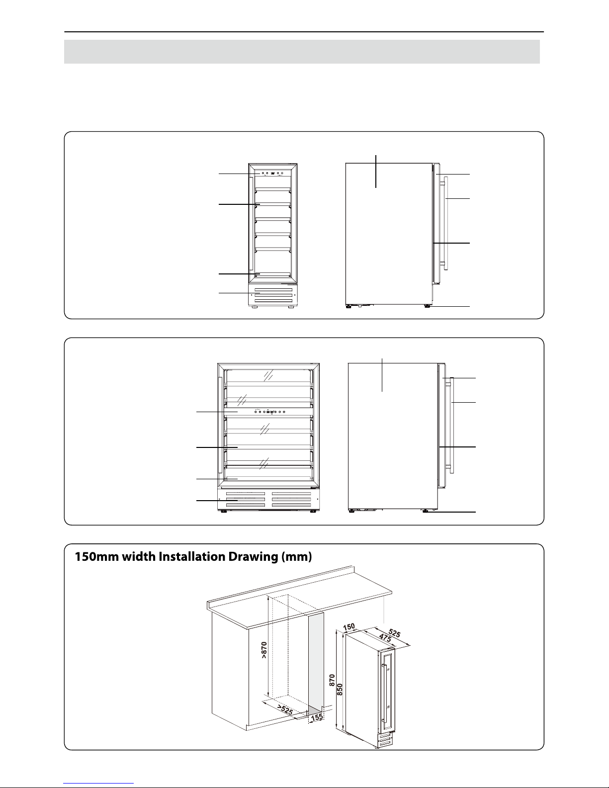
STURCTURE AND DESCRIPTION
The following pictures only show the structure of the appliance� The dimension and
shelf quantity may differ among the models of the same series�
BUILT-UNDER SERIES
(Built under a kitchen table top)
Touch-Key Control Panel
& Digital Display
Deep Shelf
Shallow Shelf
Front Louver
Leveling Foot
Outside Canbinet
Handle
Door
Gasket
Single Zone Structure
Touch-Key Control Panel
& Digital Display
Deep Shelf
Front Louver
Shallow Shelf
Leveling Foot
Outside Canbinet
Handle
Door
Gasket
Dual Zone Structure
Page 5
�3�
INSTRUCTION MANUAL
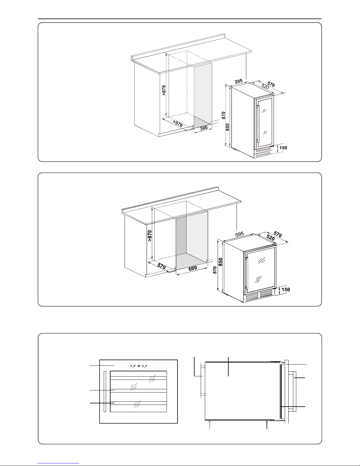
295mm width Installation Drawing (mm)
595mm width Installation Drawing (mm)
BUILT-IN-COLUMN SERIES
(Built into a kitchen cabinet)
Single Zone Structure
Touch-Key Control Panel
& Digital Display
Handle
Deep Shelf
Door
Shallow Shelf
Gasket
Outside CanbinetCondenser
Leveling Foot Mounting Bar
Page 6
�4�
INSTRUCTION MANUAL
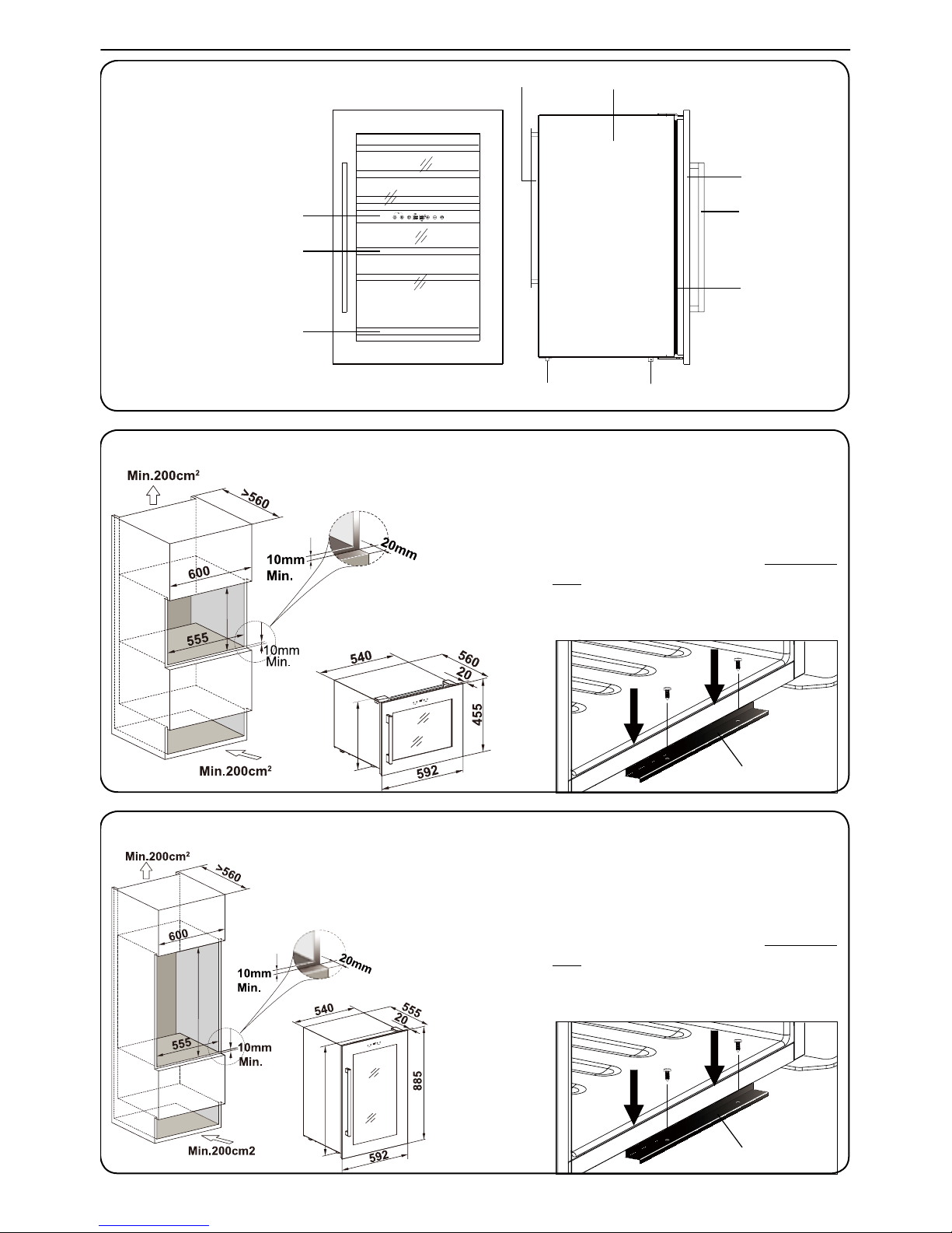
Touch-Key Control Panel
& Digital Display
Handle
Deep Shelf
Door
Shallow Shelf
Gasket
Outside Canbinet
Condenser
Leveling Foot
Mounting Bar
1� Before inserting the unit into the kitchen cabinet, please unscrew
the original 4 leveling feet (in white), and screw the 2
short leveling feet (in black), which are packed as
the accessory, to the front bottom of the unit�
2� Tighten the 2 screws to fix the Mounting
Bar (which has been fixed on the bottom
of the unit) to the kitchen cabinet� See
below drawing�
453
451
455mm Height Installation Drawing
Mounting Bar
1� Before inserting the unit into the kitchen cabinet, please unscrew
the original 4 leveling feet (in white), and screw the 2
short leveling feet (in black), which are packed as
the accessory, to the front bottom of the unit�
2� Tighten the 2 screws to fix the Mounting
Bar (which has been fixed on the bottom
of the unit) to the kitchen cabinet� See
below drawing�
855mm Height Installation Drawing
876
878
Mounting Bar
Page 7
�5�
INSTRUCTION MANUAL
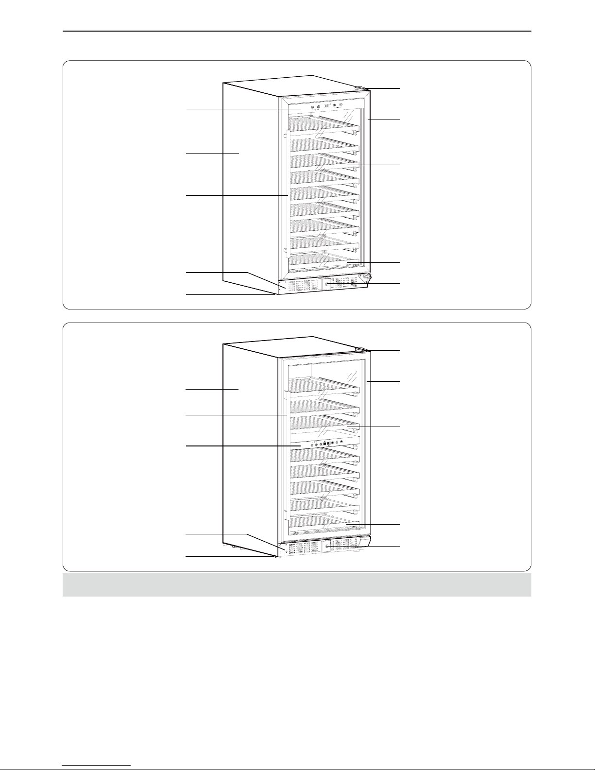
FLOOR-STANDING SERIES
Dual Zone Structure
Single Zone Structure
Touch-Key Control Panel
& Digital Display
Deep Shelf
Front Louver
Shallow Shelf
Lock
Leveling Foot
Outside Canbinet
Handle
Door
Upper Right Hinge
Touch-Key Control Panel
& Digital Display
Deep Shelf
Front Louver
Shallow Shelf
Lock
Leveling Foot
Outside Canbinet
Handle
Door
Upper Right Hinge
ACCESSORY INSTALLATION BEFORE OPERATING
UNPACKING AND CLEANING THE WINE COOLER
•
Remove the exterior and interior packing materials�
•
Let the appliance stand upright for approximately 2 hours before connecting it to the
power source, which helps to reduce the possibility of a cooling-system malfunction
from handling during transportation�
•
Use a soft cloth to clean the interior surface with lukewarm water�
•
Install the door handle provided with the appliance by following these steps:
Page 8
�6�
INSTRUCTION MANUAL
1st Step -Remove the gasket on the internal door
Gasket
Flat Washer
Locker Washer
Screw
Handle
Door Frame
to expose the two screw holes�
2nd Step -Install the handle tightly with the
screws and washers provided�
3rd Step -Restore the gasket�
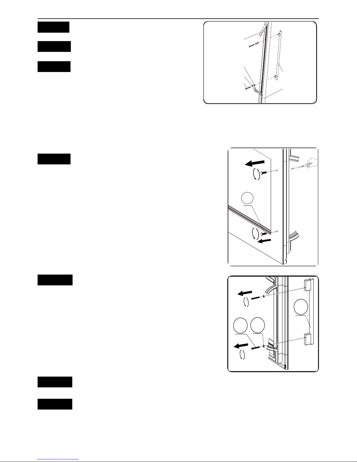
HOW TO REVERSE THE DOOR HANDLE
For a unit with reversible door swing function, please follow the following steps to
reverse the door handle (based on the door handle has been originally installed on the
left side of the front door)�
1st Step - Remove the gasket at the right inner side of
Figure1
1
the door to expose the 2 decoration screws
A
� Unscrew them in a clockwise direction
with a straight screwdriver at first, and then
loosen them in a counter-clockwise direction
by fingers from the outer side of the door�
Now the screw holes are ready for installing
the handle to the right side� See Figure 1�
2nd Step - Remove the gasket at the left inner side of
Figure2
2
3
4
the door to expose the 2 handle screws B�
Unscrew them in a counter-clockwise
direction with a cross screwdriver, take out
the screws and the washers C as well as the
handle D� See Figure 2�
3rd Step - Install the handle to the outer right side of the door� See Figure 3�
4th Step - install the 2 decoration screws E to the holes at the left side of the outer
door (backwards to the steps of unscrewing it)� See Figure 4�
Page 9

�7�
INSTRUCTION MANUAL
5th Step - Tidy and restore the gasket�
Figure3
23
4
Figure4
5
LOCK & UNLOCK THE DOOR (FOR OPTION)
●•
Lock is an optional function� If your Wine Cooler has such function, a key should be
attached inside the packing of this Manual�
●•
Insert the key into the lock and turn it counter-clockwise to unlock the door� To lock
it, please follow the reversed operation� Please save the key well�
OPERATING THE WINE COOLER
WORKING CLIMATE
•
The appliance is designed for operating from SN to T climate (see below climate class
chart)� It is recommended to maintain the ambient around 22-25°C which helps the
appliance working with low power consumption�
Climate Class Ambient Temperature
SN 10 - 32 °C
N 16 - 32 °C
ST 18 - 38 °C
T 18 - 43 °C
•
If the ambient temperature is above or below the designed climate range, the
performance of the unit may be affected� For example, the appliance operating in
extreme cold or hot conditions may cause interior temperatures to fluctuate, and the
temperature set 5-22°C may not be reached sometimes�
Page 10

�8�
INSTRUCTION MANUAL
WINE STORAGE
•
The standard shelves are designed perfectly for Bordeaux bottle storage� The
maximum loaded bottles may vary subject to the different size or dimension wine
bottles you store�
•
The shelves can be pull out approximately by 1/3 for easy access to the wine storage,
while it is designed with a plastic stopper on each sides of the shelf track to prevent
bottles from falling�
•
To prevent damaging the door gasket, make sure to have the door opened fully all
the way before pulling the shelves out�
•
Please store wine in sealed bottles�
•
Do not cover the shelves with aluminum foil or any other shelf material which may
prevent air circulation�
•
Should the wine cooler be left empty for long periods it is suggested that the
appliance is unplugged, and after careful cleaning, leave the door ajar to allow air to
circulate inside the cabinet in order to avoid possible condensation, mold or odours
forming�
•
Recommended temperatures for chilling/storing your wines�
Red Wines 15 - 18
ºC
Dry/White Wines 9 - 14
ºC
Rose Wines 0 - 11
ºC
Sparkling Wines 5 - 8
ºC
Page 11

�9�
INSTRUCTION MANUAL
CONTROL PANEL
•
For Single Zone
Power Lighting
Temp.Up
Display Window Temp.Down
Lock / Unlock
ºC/ºF
Interchange
•
For Dual Zone
Power Lighting
Temp.Up
Upper Zone
Display Window
Bottom Zone
Display Window
Zone Select
Temp.Down
Lock / Unlock
ºC/ºF
Interchange
POWER ON/OFF CONTROL
•
When the appliance is plugged in to a power outlet, it powers on automatically�
•
Touch the power mark and hold for 10 seconds to turn off (or turn on) the
appliance�
•
No matter it is under a locked or unlocked situation, you can turn off the appliance by
touching the power mark
and holding for 10 seconds�
Page 12

�10�
INSTRUCTION MANUAL
Warning:
To avoid breaking the compressor, please do not turn on the appliance again within
5 minutes after you turn it off�
UNLOCKING THE CONTROL PANEL
•
To unlock the control panel, touch the power mark and lighting mark
with 2 fingers at the
same time and hold for 3 seconds � When unlocked a buzz sound will be heard�
•
The control panel will be automatically locked with a buzz sound heard after 10
seconds without being touched�
•
Under the locked situation, the control panel will not react to any touching (except
the power mark which works as above Power On/Off Control description)�
INTERIOR LIGHTING ON/OFF CONTROL
•
Under the unlocked situation, touch the lighting mark to turn on (or turn off ) the
interior cool LED lighting�
•
The lighting will be continuously on if it is not turned off�
•
The control panel will be automatically locked with a buzz sound heard after 10
seconds without being touched�
•
Under the locked situation, the control panel will not react to any touching (except
the power mark
which works as above Power On/Off Control description)�
•
Touch the power mark and lighting mark with 2 fingers at the same time and
hold for 3 seconds to unlock the control panel� When unlocked a buzz sound will be
heard�
TEMPERATURE DISPLAY WINDOW
•
The temperature is displayed in digital which is the best way to be read out� The
digital is shown as the set temperature when you are setting the temperature, and it
will change to be the real temperature of the inside cabinet after 10 seconds without
being touched�
•
When the temperature probe is out of order, the display window will show with “HH”
or “LL” instead of a digital figure while continuous buzz sound will be heard� In case
of this happens, this appliance is considerately designed to keep periodical running
of compressor and fans which helps to keep the coldness of the inside cabinet to
protect your stored wines�
Warning:
To avoid destroying your stored wines, it is strongly recommended to have the
appliance repaired immediately, as the spare periodical running can not ensure the
Page 13

�11�
INSTRUCTION MANUAL
appliance to achieve the temperature you have set�
TEMPERATURE SETTING
For Single Zone
•
The temperature setting range is 5-22 ºC (41-72 ºF)�
•
Directly touch the or mark to set the wine cooler temperature as you want�
•
The first touch on or mark will recall the previous set temperature displayed
in the digital window� If the appliance runs after a power failure (or unplugging), the
previous set temperature does not exist and is replaced by the defaulted temperature
at 12ºC�
•
Touch the mark to increase the set temperature by 1ºC� On the contrary, touch
the mark to decrease the set temperature by 1ºC�
•
The digital will change to display the real temperature of the inside cabinet after 10
seconds without being touched�
For Dual Zone
•
The temperature setting ranges are 5-12 ºC (41-54 ºF) for the upper zone and 12-22
ºC
(54-72 ºF) for the bottom zone�
•
You need to select the set zone by touching the mark before touching the mark
or to set the wanted temperature� The display window with digital flashing
indicates the zone ready for temperature setting�
•
The first touch on mark or will recall the previous set temperature displayed
in the digital window� If the appliance runs after a power failure (or unplugging), the
previous set temperature does not exist and is replaced by the defaulted temperature
at 10ºC for the upper zone while 16ºC for the bottom zone�
•
Touch the mark to increase the set temperature by 1ºC� On the contrary, touch
the mark to decrease the set temperature by 1ºC�
•
The digital will change to display the real temperature of the inside cabinet after 10
seconds without being touched�
Note:
For the first time to use the appliance or to restart the appliance after having been
shut off for a long time, you may find a few degrees variance between the set
temperature and the displayed temperature� It is normal and everything of the
appliance will be in the order after a few hours running
SELECTING FAHRENHEIT(ºF) & CELSIUS (ºC) DISPLAY
For Single Zone
Touch the marks with 2 fingers at the same time and hold for 5 seconds, you
can interchange the Fahrenheit and Celsius display�
Page 14

�12�
INSTRUCTION MANUAL
For Dual Zone
Directly touch the mark
, you can interchange the Fahrenheit and Celsius display
for both zones at the same time�
CARE AND MAINTENANCE
CLEANING THE WINE COOLER
•
Turn off the power, unplug the appliance, and remove all items including shelves�
•
Wipe the inside surfaces with a sponge and baking soda solution� The solution should
be about 2 tablespoons of baking soda to a quart (approx� 1 litre) of warm water�
•
Wash the shelves with a mild detergent solution� Allow wooden shelves to dry before
placing back into the wine cooler�
•
Wring excess water out of the sponge or cloth when cleaning area of the controls, or
any electrical parts�
•
Wipe the outside cabinet with warm water and mild liquid detergent� Wipe dry with
a clean soft cloth�
•
Do not use steel wool or steel brush on the stainless steel� These will contaminate the
stainless steel with steel particles and rusting may occur�
POWER FAILURE
Most power failures are corrected within a few hours and should not affect the
temperature of your appliance if you minimize the number of times of door opening�
If the power is going to be off for a longer period of time, you need to take the proper
steps to protect your contents�
MOVING THE WINE COOLER
•
Remove all items�
•
Securely tape down all loose items (shelves) inside your appliance�
•
Turn the adjustable leg up to the base to avoid damage�
•
Tape the door shut�
•
Be sure the appliance stays secure in the upright position during transportation� Also
protect outside of appliance with a blanket, or similar item�
ENERGY SAVING TIPS
•
The appliance should be located away from heat producing appliances, and away
from direct sunlight�
•
Ensure that the unit is adequately ventilated� Never cover air vents�
•
Only open the door when necessary� Avoid leaving the door open for long periods or
opening/closing the door frequently�
Page 15

�13�
INSTRUCTION MANUAL
TROUBLESHOOTING
If you feel the appliance is out of order, follow these instructions to try to see if you
can solve the problem simply by yourself before calling for service�
No� PROBLEM PROBLEM POSSIBLE CAUSE / MEASURE
1 The wine cooler does not operate
Not plugged in�
The awwwppliance is turned off�
The circuit breaker tripped or a blown fuse�
2 The wine cooler is not cold enough
Check the temperature control setting�
External environment may require a higher setting�
The door is opened too frequently�
The door is not closed completely�
The door gasket does not seal properly�
3
Automatically turn-on and
turn-off frequently
The room temperature is hotter than normal�
A large amount of contents has been added to the wine
cooler�
The door is opened too frequently�
The door is not closed completely�
The temperature control is not set correctly�
The door gasket does not seal properly�
4 The lighting does not work
Not plugged in�
The circuit breaker tripped or a blown fuse�
The lighting is turned off�
5 Too much vibration
Check to assure that the appliance is level�
Check to assure no parts inside the cabinet or in the
compressor chamber are loose�
6
The wine cooler seems to make
too much noise
The rattling noise may come from the flow of the
refrigerant, which is normal�
As each cycle ends, you may hear gurgling sounds
caused by the flow of refrigerant�
Contraction and expansion of the inside walls may
cause popping and crackling noises�
The appliance is not level�
7 The door will not close properly�
The wine cooler is not level�
The door was reversed and not properly installed�
The gasket is dirty�
The shelves are out of position�
8
The display window is shown with “HH”
or “LL” instead of a digital figure,
and/or with continuous buzz sound�
The temperature probe is out of order�
Page 16

�14�
INSTRUCTION MANUAL
REVERSE THE DOOR SWING
FOR BUITL-UNDER SERIES
Remarks:
●•
Reversible door swing function is only available for a unit with 870mm height, and
with control panel inside the cabinet�
●•
The instruction is based on a unit with right door hinge installed already�
●•
To reserve the door from right hinge to left hinge, you need to get ready 2 new spare
parts: an upper left hinge, and a bottom left hinge�
●•
All removed parts must be saved to do the door reinstallation, except those remarked
with “Disused”�
1st Step -Open the door, and loosen the 2 screws A and B� See Figure 1�
2nd Step -Carefully remove the door from the upper right hinge D and prevent it
from scratching� Take out the support rod Cfrom the door hinge hole� See
Figure 2�
3rd Step -Pull out the 6 decorating plastic bolts covering the reserved hinge screw
holes at the front left corner of the cabinet�
4th Step -Unscrew the upper right hinge D(Disused) and bottom left hinge
F
(Disused) from the cabinet� See Figure 3�
-install the upper left hinge Gand bottom left hingeH to the left side of the
cabinet� Make sure the screws are tightened� See Figure 4�
5th Step -Reverse the door handle by following the instruction of “How to Reverse the
Door Handle” as mentioned above�
6th Step -Cover the hinge screw holes on the right side with the 6 decorating plastic
bolts�
Page 17

�15�
INSTRUCTION MANUAL
FOR BUILT-IN-COLUMN SERIES
Remarks:
●•
Reversible door swing function is only available for a unit with 4 handle screw holes
reserved on the front door (2 at the left side and 2 at the left side)�
●•
The instruction is only suitable for a unit with control panel on the door�
●•
The instruction is based on a unit with right door hinge installed already�
●•
To reserve the door from right hinge to left hinge, you need to get ready 3 new spare
parts: upper left hinge, upper left hinge cover, right door corner cover�
●•
All removed parts must be saved to do the door reinstallation, except those remarked
with “Disused”�
1st step – Takedown the Door� See Figure 1�
1� Loosen the 2 screws
with a cross screwdriver, and take out the upper right
hinge cover (Disused)� There are two wiring harnesses
D& E
with their terminals
connected together�
2�Disconnect the two wiring harnesses, and loosen the 3 screws
to take out the
upper right hinge�
3� Loosen the 4 screws
& the 1 screw Hto take out the bottom hinge�
4� Carefully take the whole door out�
7
3b
8
Figure1
1a
2
3a
4
6
5
7
3b
8
9
10
1a
2
3a
Page 18

�16�
INSTRUCTION MANUAL
2nd step – Tidy the Door�
1� Pull the harness wires one by one out of the upper
Figure2
5
6
right hinge hole through its gap, and remove the
upper right hinge (Disused)� See Figure 2�
2� Tidy the harness and carefully push back it into the
Figure3
11
door frame, and cover it with the right door corner
cover K� See Figure 3�
Remarks:
If it is difficult to push back the harness into the door frame, please follow the steps in
Figure 4 & 5�
Figure4
Figure5
1 Remove the gasket at the upper inner side of the door to expose the display back
cover�
2� Carefully prize up the back cover by a straight screwdriver� Then slowly draw the
harness into the door frame� and tidy the gasket�
3� Insert a straight screwdriver to the groove of the left
Figure6
12
door corner cover L, and prize it up� See Figure 6�
Page 19

�17�
INSTRUCTION MANUAL
4�Slowly pull out the harness M at the left door corner,
Figure7
14
13
which must be ensured no longer than 90mm to
avoid loosen the inside terminals� Insert the harness
wires one by one into the upper left hinge hole
through its gap� See Figure 7�
3rd step – Tidy the Cabinet� See Figure 8�
1� Loosen the 2 screws to take out the harness cover O from the top left side of the
cabinet�
2� Install the harness cover at the top right side of the cabinet to cover the harness
there�
3� Install the bottom hinge at the bottom left side of the cabinet with 4 screws
�
Figure8
1b
15
1b
15
1b
7
3b
1b
15
1b
1b
15
7
3b
Mounting Bar
4th step – Install the Door� See Figure 9�
1� Install the upper left hinge N at the top left side of the cabinet with 3 screws �
2� Fix the door to the bottom hinge with a screw H�
3� Connect the two wiring harnesses M & Q through their terminals�
4� Tidy the harnesses and install the upper left hinge cover P with the screw �
Page 20

�18�
INSTRUCTION MANUAL
Figure9
16
1a
3a
14
13
17
8
16
1a
3a
14
13
17
8
5th step – Reverse the Door Handle�
Reverse the door handle by following the instruction of “
How to Reverse the Door Handle”
as mentioned above�
FOR FLOOR-STANDING SERIES
Remarks:
●•
Reversible door swing function is only available for a unit with control panel inside
the cabinet�
●•
The instruction is based on a unit with right door hinge installed already�
●•
All removed parts must be saved to do the door reinstallation�
1st step - Prize up the hinge screw holes cover A and
Figure1
hinge cover B with a straight screwdriver� Take
out the upper hinge by loosening the screws
, and lift up the whole door� See Figure 1�
Page 21

�19�
INSTRUCTION MANUAL
2nd step - Move the support rod F (at the bottom of the door) from the right to the
left side� Move the hinge hole cover (at the top of the door) from the left
side to the right side� See Figure 2 & 3�
Figure2
Figure3
3rd step - Pull out the bottom hinge cover I, and take out the bottom hinge by
loosing the screws� Loose the 4 screws on the bottom left side� Install the
bottom hinge to the left side while screw the holes on the right side� See
Figure 4�
4th step - To reinstall the door to the opposite side, insert the door support rod to
the bottom hinge through a washer K, and screw the upper hinge which
has connected with the door� Finally, cover the hinges as well as the hinge
screw holes� See Figure 5 & 6�
Figure5
Figure6
5th step – Reverse the door handle by following the instruction of “How to Reverse
the Door Handle” as mentioned above�
Page 22

�20�
INSTRUCTION MANUAL
ENERGY LABEL
Page 23

�21�
INSTRUCTION MANUAL
Page 24

�22�
INSTRUCTION MANUAL
Page 25

�23�
INSTRUCTION MANUAL
 Loading...