


FDSR25GF
Table of contents
 Loading...
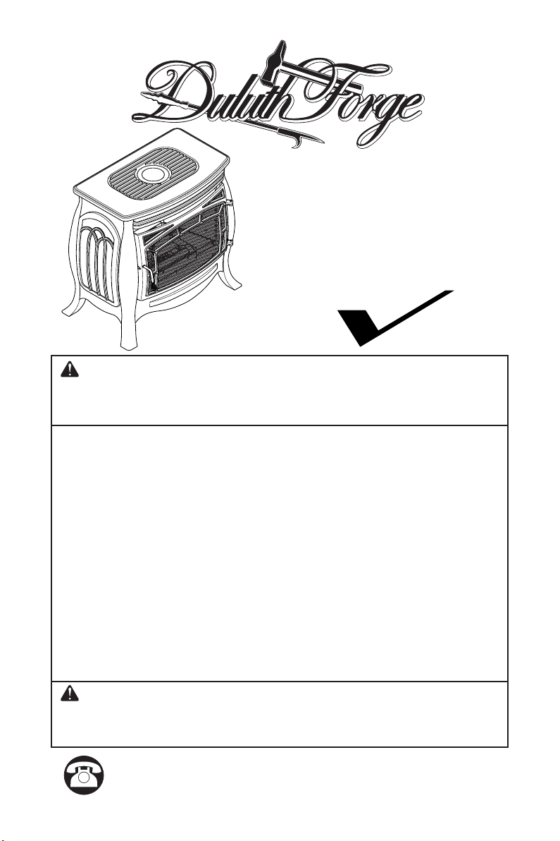
VENT-FREE GAS STOVE
US
OWNER’S OPERATION AND
INSTALLATION MANUAL
MODELS
FDSR25 & FDSR25GF
®
WARNING: If the information in this manual is not
followed exactly, a re or explosion may result causing
property damage, personal injury or loss of life.
— Do not store or use gasoline or other ammable va-
pors and liquids in the vicinity of this or any other
appliance.
— WHAT TO DO IF YOU SMELL GAS
• Do not try to light any appliance.
• Do not touch any electrical switch; do not use any
phone in your building.
•
Immediately call your gas supplier from a neighbor’s
phone. Follow the gas supplier’s instructions.
• If you cannot reach your gas supplier, call the re
department.
—
Installation and service must be performed by a qualied installer, service agency or the gas supplier.
WARNING: This appliance is equipped for natural and
propane gas. Field conversion is not permitted other than
between natural or propane gases.
Questions, problems, missing parts? Before returning to your retailer, call
our customer service department at 1-855-607-6557, 8:00 am - 4:30 pm EST,
Monday through Friday or email info@factorybuysdirect.com
TABLE OF CONTENTS
Safety ........................................................ 3
Specications ............................................ 4
Qualied Installing Agency ........................ 5
Product Features ....................................... 5
Local Codes............................................... 5
Product Identication ................................. 6
Unpacking.................................................. 6
Water Vapor: A By-Product Of
Unvented Room Heaters ..................... 6
Air For Combustion and Ventilation ........... 7
Installation ................................................. 8
Operation ................................................. 18
Inspecting Burners................................... 22
Care And Maintenance ............................ 23
Electrical .................................................. 24
Troubleshooting ....................................... 26
Service Hints ........................................... 29
Technical Service..................................... 29
Accessories ............................................. 29
Parts ........................................................ 30
Replacement Parts .................................. 31
Warranty .................................................. 32
SAVE THIS BOOK
INSTALLER: Leave this manual with the appliance.
CONSUMER: Retain this manual for future reference.
This is an unvented gas-red stove. It uses air (oxygen)
from the room in which it is installed. Provisions for adequate combustion and ventilation air must be provided.
Refer to Air For Combustion and Ventilation section on
page 7 of this manual.
WARNING: Improper installation, adjustment, al-
teration, service or maintenance can cause injury or
property damage. Refer to this manual for correct installation and operational procedures. For assistance
or additional information consult a qualied installer,
service agency or the gas supplier.
This appliance may be installed in an aftermarket,* permanently located, manufactured (mobile) home, where
not prohibited by local codes.
This appliance is only for use with propane or natural
gas. Field conversion by any other means including the
use of a kit is not permitted.
* Aftermarket: Completion of sale, not for purpose of resale, from the manufacturer.
PATENT INFORMATION
This product may be covered by one or more of the following United States patents:
8,915,239 8,851,065 8,764,436 8,757,202 8,757,139 8,752,541 8,568,136
8,545,216 8,517,718 8,516,878 8,506,290 8,465,277 8,317,511 8,297,968
8,281,781 8,241,034 8,235,708 8,152,515 8,011,920 7,967,006 7,967,007
7,654,820 7,730,765 7,677,236 7,607,426 7,434,447
www.factorybuysdirect.com
200257-01A2
SAFETY
IMPORTANT: Read this owner’s
manual carefully and completely
before trying to assemble,
operate, or service this stove.
Improper use of this stove can
cause serious injury or death
from burns, fire, explosion,
electrical shock and carbon
monoxide poisoning. Failure
to follow these instructions will
void the warranty.
Only a qualied installer, service
agent, or local gas supplier may
install and service this product.
WARNING: Keep the appli-
ance area clear and free from
combustible materials, gasoline,
and other ammable vapors and
liquids.
WARNING: This appliance
can be used with propane or
natural gas. It is shipped from
the factory adjusted for use with
propane.
DANGER: Carbon monoxide
poisoning may lead to death!
CARBON MONOXIDE POISONING: Early
signs of carbon monoxide poisoning resemble
the u, with headaches, dizziness or nausea.
If you have these signs, the stove may not be
working properly. Get fresh air at once! Have
stove serviced. Some people are more affected by carbon monoxide than others. These
include pregnant women, people with heart or
lung disease or anemia, those under the inuence of alcohol and those at high altitudes.
NATURAL AND PROPANE/LP GAS: Natural
and Propane/LP gas are odorless. An odormaking agent is added to the gas. The odor
helps you detect a gas leak. However, the
odor added to the gas can fade. Gas may be
present even though no odor exists.
WARNING: Any change to
this stove or its controls can be
dangerous.
WARNING: Do not allow fans
to blow directly into stove. Avoid
any drafts that alter burner ame
patterns.
WARNING: Do not use a
blower insert, heat exchanger
insert or other accessory not
approved for use with this stove.
WARNING: Due to high temperatures, the appliance should
be located out of trafc and away
from furniture and draperies.
WARNING: Do not place
clothing or other flammable
material on or near the appliance. Never place any objects
in the stove.
WARNING: The stove becomes very hot when operating.
Keep children and adults away
from hot surfaces to avoid burns
or clothing ignition. Stove will
remain hot for a time after shut-
down. Allow surfaces to cool
before touching.
WARNING: Carefully supervise young children when they
are in the room with the stove.
WARNING: You must operate this stove with the door and
screen in place.
www.factorybuysdirect.com
3200257-01A

SAFETY
1. Do not place Propane/LP supply tank(s)
inside any structure. Propane/LP supply
tank(s) must be placed outdoors.
2. This stove shall not be installed in a bedroom or bathroom.
3. This stove needs fresh air ventilation to
run properly. This stove has an Oxygen
Depletion Sensing (ODS) safety shutoff
system. The ODS shuts down the stove if
not enough fresh air is available. See Air
for Combustion and Ventilation, pages 7.
If stove keeps shutting off, see Trouble-
shooting, page 26.
4. Keep all air openings in front and bottom
of stove clear and free of debris. This will
ensure enough air for proper combustion.
5. If stove shuts off, do not relight until you
have provided fresh, outside air. If stove
keeps shutting off, have it serviced.
6. Do not run stove:
• Where ammable liquids or vapors are
used or stored.
• Under dusty conditions.
7. Before using furniture polish, wax, carpet
cleaner, or similar products, turn stove off.
If heated, the vapors from these products
may create a white powder residue within
burner box or on adjacent walls or furni-
ture.
8. Do not use stove if any part has been
under water. Immediately call a qualied
service technician to inspect the room
stove and to replace any part of the control
system and any gas control which has
been under water.
9. Turn stove off and let cool before servicing. Only a qualied service person should
service and repair stove.
10. Operating stove above elevations of 4,500
feet could cause pilot outage.
11. To prevent performance problems, do
not use propane/LP fuel tank of less than
100 lbs. capacity.
12. Do not use this stove as a wood-burning
stove. Use only the logs provided with the
stove.
13. Solid fuels should not be burned in a stove
in which a vent-free log set is installed. Do
not use this stove to cook food or burn
paper or other objects.
14. To prevent sooting, follow the instructions
in Care and Maintenance (see page 23).
15. Do not add extra logs or ornaments such
as pine cones, vermiculite, or rock wool.
Using these added items can cause sooting. Do not add lava rock around base.
Rock and debris could fall into the control
area of stove. After servicing, always close
door before operating stove.
16. This stove is designed to be smokeless. If
logs ever appear to smoke, turn off stove
and call a qualied service person.
Note: During initial operation, slight smok-
ing could occur due to log curing and the
stove burning manufacturing residues.
17. Do not use this stove if any log is broken.
Do not operate stove if a log has a chip
(dime-sized of larger).
SPECIFICATIONS
Gas Type Natural Gas Propane Gas
Input Rating 26,000 Btu/Hr 26,000 Btu/Hr
Ignition Electronic Piezo Electronic Piezo
Regulator Pressure Setting 4" W.C. 9" W.C.
Inlet Gas Pressure* (inches of water)
(*for purposes of input adjustment)
Stove Dimensions (HxWxD) •
Carton Dimensions (HxWxD) •
Stove Weight • 73 lbs Shipping Weight • 85 lbs
120 Volts • 19 Watts
www.factorybuysdirect.com
Maximum 9" Maximum 14"
Minimum 5" Minimum 11"
26.125" × 28" × 16.875"
31.125" × 31.375" × 20.5"
200257-01A4

QUALIFIED INSTALLING AGENCY
Only a qualied agency should install and
replace gas piping, gas utilization equipment
or accessories, and repair and equipment servicing. The term “qualied agency” means any
individual, rm, corporation, or company that
either in person or through a representative
is engaged in and is responsible for:
PRODUCT FEATURES
SAFETY PILOT
This stove has a pilot with an Oxygen Depletion Sensing (ODS) safety shutoff system.
The ODS/pilot shuts off the stove if there is
not enough fresh air.
PIEZO IGNITION SYSTEM
This stove is equipped with an electronic piezo
control system. This system requires one AAA
battery (provided).
THERMOSTATIC CONTROL
The control automatically cycles the burner
on and off to maintain a desired room tem-
perature.
a) Installing, testing, or replacing gas piping
or
b) Connecting, installing, testing, repairing,
or servicing equipment; that is experienced
in such work; that is familiar with all precautions required; and that has complied with
all the requirement of the authority having
jurisdiction.
2 GAS OPTIONS AVAILABLE
Your stove is equipped to operate on either
Propane/LP or Natural gas. The stove is
shipped from the factory ready for connecting to Propane/LP. The stove can easily be
changed to Natural gas by having your qualied installer follow the instructions on page
10 and the markings on the stove.
MANUAL OVERRIDE CONTROL
SYSTEM
This stove has two operation functions. Remote Control and Manual Override Control.
The remote control has a transmitter, which
requires two AAA batteries and electric power
outlet to operate. In the event of a power
outage, you can operate the the stove by
manual override.
LOCAL CODES
Install and use stove with care. Follow all local
codes. In the absence of local codes, use the
latest edition of The National Fuel Gas Code,
ANSI Z223.1/NFPA 54*.
*Available from:
American National Standards Institute, Inc.
1430 Broadway
New York, NY 10018
National Fire Protection Association, Inc.
1 Batterymarch Park
Quincy, MA 02269-9101
This stove is designed for vent-free operation.
State and local codes in some areas prohibit
the use of vent-free stoves.
www.factorybuysdirect.com
State of Massachusetts: The installation
must be made by a licensed plumber or
gas tter in the Commonwealth of Massachusetts.
Sellers of unvented propane or natural
gas-red supplemental room heaters shall
provide to each purchaser a copy of 527
CMR 30 upon sale of the unit.
In the State of Massachusetts the gas
cock must be a T-handle type. The State
of Massachusetts requires that a exible
appliance connector cannot exceed three
feet in length.
5200257-01A
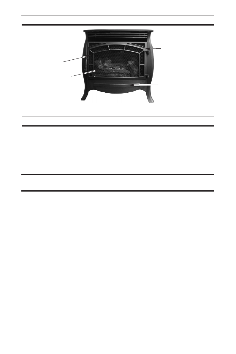
Screen
PRODUCT IDENTIFICATION
Stove Door
Logs
Stove Controls
(Inside Panel)
Figure 1 - Vent-Free Stove
UNPACKING
1. Remove top inner pack.
2. Tilt carton so that stove is upright.
3. Remove protective side packaging.
4. Slide stove out of carton.
5. Remove protective plastic wrap.
WATER VAPOR: A BY-PRODUCT OF
UNVENTED ROOM HEATERS
Water vapor is a by-product of gas combustion. An unvented room heater produces approximately one (1) ounce (30 mL) of water
for every 1,000 BTUs (0.3 KWs) of gas input
per hour. Unvented room heaters are recommended as supplemental heat (a room) rather
than a primary heat source (an entire house).
In most supplemental heat applications, the
water vapor does not create a problem. In
most applications, the water vapor enhances
the low humidity atmosphere experienced
during cold weather.
6. Rotate door handle and open door.
7. Carefully remove logs.
8. Carefully unwrap logs.
9. Check for any shipping damage. If stove
or log is damaged, contact our customer
service department.
The following steps will help ensure that water
vapor does not become a problem.
1. Be sure the heater is sized properly for the
application, including ample combustion
air and circulation air.
2. If high humidity is experienced, a dehumidier may be used to help lower the
water vapor content of the air.
3. Do not use an unvented room heater as
the primary heat source.
www.factorybuysdirect.com
200257-01A6
AIR FOR COMBUSTION AND VENTILATION
Ventilation
WARNING: This heater shall
not be installed in a conned
space or unusually tight construction unless provisions are
provided for adequate combustion and ventilation air. Read the
following instructions to insure
proper fresh air for this and other
fuel-burning appliances in your
home.
Today’s homes are built more energy efcient
than ever. New materials, increased insulation
and new construction methods help reduce
heat loss in homes. Home owners weather
strip and caulk around windows and doors
to keep the cold air out and the warm air in.
During heating months, home owners want
their homes as airtight as possible.
While it is good to make your home energy
efcient, your home needs to breathe. Fresh
air must enter your home. All fuel-burning appliances need fresh air for proper combustion
and ventilation.
Exhaust fans, replaces, clothes dryers and
fuel burning appliances draw air from the
house to operate. You must provide adequate
fresh air for these appliances. This will insure
proper venting of vented fuel-burning appliances.
WARNING: This heater shall
not be installed in a room or
space unless the required volume of indoor combustion air
is provided by the method described in the National Fuel Gas
Code, ANSI Z223.1/NFPA 54, the
International Fuel Gas Code, or
applicable local codes.
WARNING: If the area in which
the heater may be operated does
not meet the required volume for
indoor combustion air, combustion and ventilation air shall be
provided by one of the methods
described in the National Fuel
Gas Code, ANSI Z223.1/NFPA 54,
the International Fuel Gas Code,
or applicable local codes.
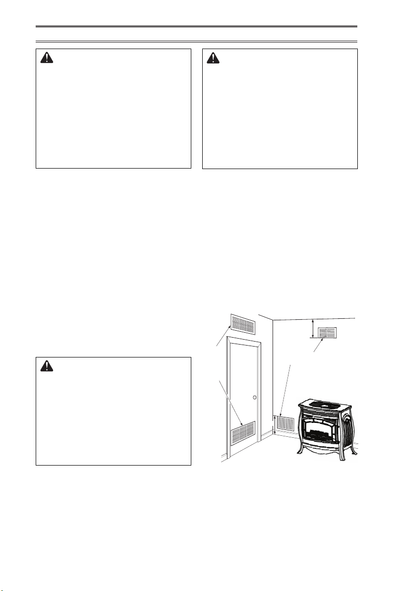
VENTILATION AIR
Ventilation Air From Inside Building
This fresh air would come from an adjoining
unconned space. When ventilating to an
adjoining unconned space, you must provide
two permanent openings: one within 12" of the
ceiling and one within 12" of the oor on the
wall connecting the two spaces (see options
1 and 2, Figure 2). You can also remove door
into adjoining room (see option 3, Figure 4).
Follow the National Fuel Gas Code, ANSI
Z223.1/NFPA 54, Air for Combustion and
Ventilation for required size of ventilation
grills or ducts.
12"
Grills Into
Adjoining
Room,
Option 1
Or
Remove
Door into
Adjoining
Room,
Option
3
Figure 4 - Ventilation Air from Inside
Into Adjoining Room,
12"
Building
Ventilation Grills
Option 2
www.factorybuysdirect.com
7200257-01A
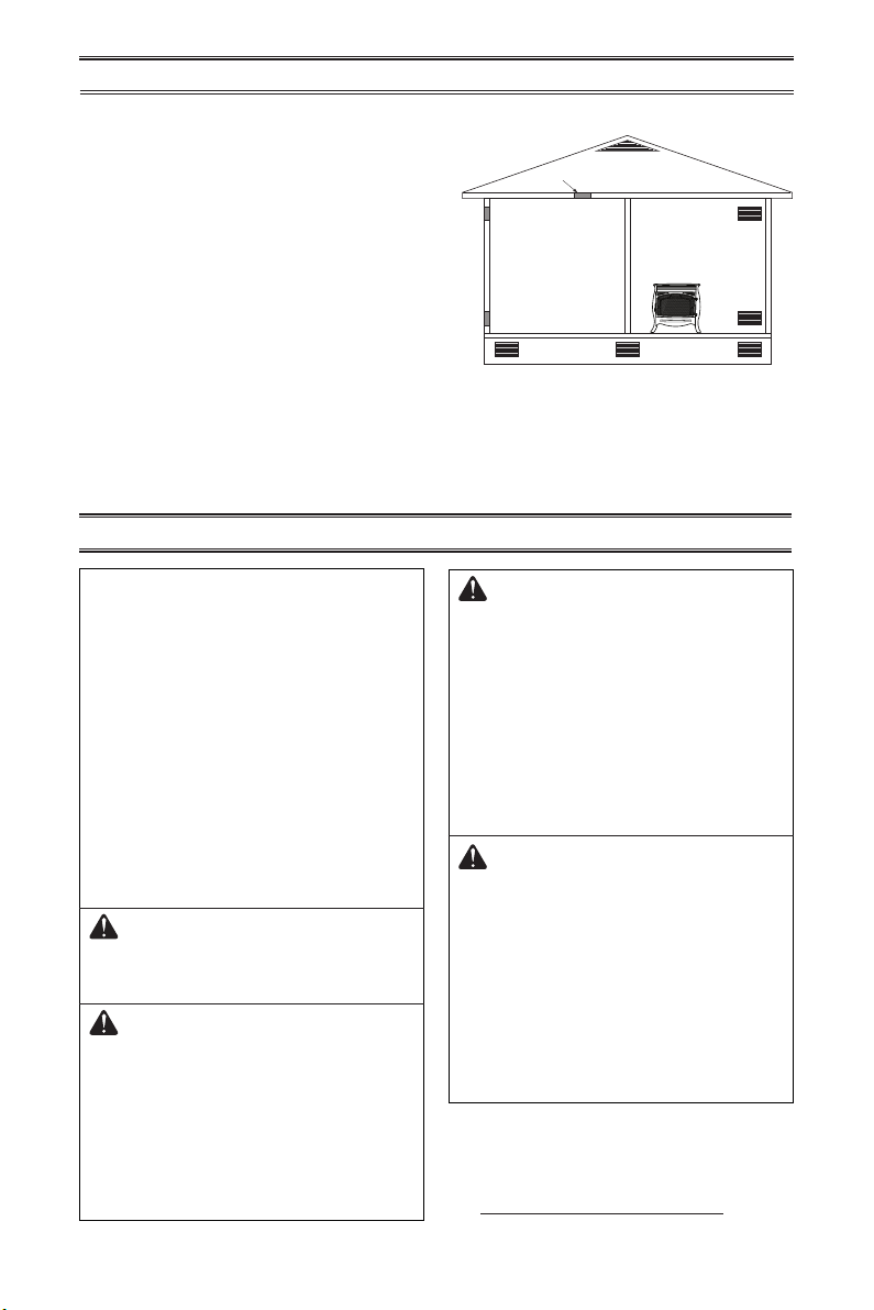
AIR FOR COMBUSTION AND VENTILATION
Ventilation Air From Outdoors
Provide extra fresh air by using ventilation
grills or ducts. You must provide two permanent openings: one within 12" of the ceiling
and one within 12" of the oor. Connect these
items directly to the outdoors or spaces open
to the outdoors. These spaces include attics
and crawl spaces. Follow the National Fuel
Gas Code, ANSI Z223.1/NFPA 54, Air for
Combustion and Ventilation for required size
of ventilation grills or ducts.
IMPORTANT: Do not provide openings
for inlet or outlet air into attic if attic has a
thermostat-controlled power vent. Heated air
entering the attic will activate the power vent.
Rework worksheet, adding the space of the
adjoining unconned space. The combined
spaces must have enough fresh air to supply
all appliances in both spaces.
INSTALLATION
Outlet
Air
Outlet
Air
Inlet
Air
Figure 5 - Ventilation Air from Outdoors
Inlet Air
Ventilated
Attic
Crawl Space
Ventilated
To Attic
To
Crawl
Space
NOTICE: This stove is intended
for use as supplemental heat.
Use this stove along with your
primary heating system. Do not
install this stove as your primary
heat source. If you have a central heating system, you may
run system’s circulating blower
while using stove. This will help
circulate the heat throughout the
house. In the event of a power
outage, you can use this stove
as your primary heat source.
WARNING: A qualied ser-
vice person must install stove.
Follow all local codes.
WARNING: Electrical Ground-
ing Instructions If using a blower,
this appliance is equipped with a
three-prong (grounding) plug for
your protection against shock
hazard and should be plugged
directly into a properly grounded
three-prong receptacle.
WARNING: Never install the
stove
• in a bedroom or bathroom
• in a recreational vehicle
• where curtains, furniture, cloth-
ing, or other ammable objects
are less than 48" from the front,
top, or sides of the stove.
• in high trafc areas
• in windy or drafty areas
CAUTION: This stove creates
warm air currents. These currents
move heat to wall surfaces next
to stove. Installing stove next to
vinyl or cloth wall coverings or
operating stove where impurities
(such as tobacco smoke, aromatic
candles, cleaning uids, oil or
kerosene lamps, etc.) in the air
exist, may cause walls to discolor.
IMPORTANT: Vent-free heaters add moisture
to the air. Although this is benecial, installing
heater in rooms without enough ventilation air
may cause mildew to form too much moisture.
See Air for Combustion and Ventilation, pages 7.
www.factorybuysdirect.com
200257-01A8
s
s
INSTALLATION
Back Wall
CONNECTING ELECTRICAL
SUPPLY
This stove requires an 120V electrical outlet
within 4 feet of the unit. This is a power supply
for the remote receiver located in the bottom
of the stove. Extensions cords may be used.
The remote receiver requires 4 AA batteries.
This powers the stove in case of an electrical
power outage.
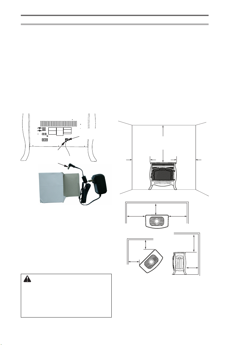
1. Locate 6V DC adapter.
2. Plug connector end of adapter into the
power change assembly on the back of
the stove.
3. Plug adapter into a 120V electrical outlet.
WARNING: Make sure Regulator Cap is in the appropriate position
ADVERTENCIA: Asegúrese la tapa del regulador esté en la posición adecuada,
as shown in diagrams. Installation and service should be done by
como se muestra en los diagramas. La instalación y reparaciones deben ser realizadas
qualified service technician only.
por un técnico de servicio calificado solamente.
Natural Gas
Gas Natural
When using natural gas:
Cuando se utiliza gas natural:
Make sure the cap is installed in the propane/LP inlet of regulator.
Asegúrese de que la tapa está instalado en el propano/LP entrada del regulador.
Use thread sealant to assure there are no leaks.
Utilice sellador de roscas para asegurar que no haya fugas.
Propane/LP Gas
Propano/LP Gas
When using propane/LP gas:
Cuando se utiliza el gas propano / LP:
Make sure the cap is installed in the natural gas (NG) inlet of regulator.
Asegúrese de que la tapa está instalado en la entrada de gas natural (GN) del regulador.
Use thread sealant to assure there are no leaks.
Utilice sellador de roscas para asegurar que no haya fugas.
Natural Gas
Shown
NG
LP
3-3.5" WC
8-11" WC
Correct Pilot Flame Pattern
Natural Gas
Shown
NG
LP
3-3.5" WC
8-11" WC
Incorrect Pilot Flame Pattern
INSTALL SUPPLIED CAP IN FITTING
INSTALAR TAPA SUMINISTRADA MONTAJE NO SE UTILIZA.
FOR PROPANE GAS SUPPLY
WARNING: Make sure the supplied cap is
PARA LA FUENTE DE GAS DEL PROPANE
installed in unused regulator fitting before
1/2 Glas
CAUTION: The heater requires an external regulator to reduce
Height
connecting the correct gas supply line.
the LP tank pressure to a maximum of 14" W.C. Never connect
Correct Burner Flame Pattern
this product directly to the supply tank.
WARNING: Do not use natural gas and
Yellow
PRECAUCIÓN: El calentador requieres una externa regulador
propane gas together.
Tipping
para reducir la presión del tanque de gas a un máximo de 14"
CAUTION: Two gas line installations at
W.C. Nunca conecte este producto directamente al tanque de
1/2 Glas
suministro.
the same time are prohibited.
Height
FOR NATURAL GAS SUPPLY
ADVERTENCIA: Asegúrese de que la línea
Incorrect Burner Flame Pattern
PARA LA FUENTE DE GAS DEL NATURAL
no utilizado se conecta por primera vez
NOTICE: An additional gas regulator will be necessary if the
antes de conectar la línea de suministro
local natural gas pressure exceeds the heater's rated maximum
LP
NG
inlet pressure. If in doubt, contact the local gas utility. If natural
de gas correcta.
Blue Plunger
Yellow Plunger
gas inlet pressure exceeds 10" W.C., the safety pressure switch
ADVERTENCIA: No utilice el gas natural y
will activate. See owners manual for proper procedure to bypass
el gas propano juntos.
the pressure switch.
PRECAUCIÓN: Dos instalaciones de
AVISO: Un regulador de gas adicional será necesario si la
presión del gas natural local excede de entrada nominal máxima
líneas de gas al mismo tiempo están
del calentador presión. En caso de duda, póngase en contacto
prohibidos.
con la compañía de gas local. Si la presión de entrada de gas
natural supera los 10" WC, el interruptor de presión de
200110-01B
seguridad se activará. Consulte el manual del propietario para el
03/15
procedimiento adecuado de derivación el interruptor de presión.
NOT BEING USED.
Gas Inlet / Gas esté
INLET GAS PRESSURE MAX 1/2 PSIG (3.5 KPa)
Connector
End of
Adapter
This appliance may be installed in an aftermarket,*
permanently located, manufactured (mobile) home, where
not prohibited by local codes.
This appliance is only for use with propane or natural gas.
Field conversion by any other means including the use of
a kit is not permitted.
Procom Heating, Inc. U.S. Patent Information
This product may be covered by one or more of the following
United States patents:
8,915,239 8,851,065 8,764,436 8,757,202 8,757,139 8,752,541
8,568,136 8,545,216 8,517,718 8,516,878 8,506,290 8,465,277
8,317,511 8,297,968 8,281,781 8,241,034 8,235,708 8,152,515
8,011,920 7,967,006 7,967,007 7,654,820 7,730,765 7,677,236
7,607,426 7,434,447
Other patents pending.
TOLL-FREE Customer Care Number: 1-866-573-0674
Numero de Atención al Cliente GRATUITO: 1-866-573-0674
Visit our website for more information www.usaprocom.com
Visite nuestra página web para más informacion www.usaprocom.com
Power Change
Assembly
This stove is designed to sit directly on the
oor or on a mantel base.
IMPORTANT: You must maintain minimum
wall and ceiling clearances during installation.
The minimum clearances are shown in Figure
7. Measure from outermost point of stove.
Minimum Wall and Ceiling
Clearances
A. Clearances from outermost point of stove
to any combustible side wall should not be
less than 12".
B. Clearances from the stove to the ceiling
should not be less than 48".
C. Clearance from stove to back wall should
not be less than 6".
Ceiling
48"
Min.
12"
Min.
Side
Wall
Side
Wall
12"
Min.
Floor
Figure 6 - Connecting to Power Supply
Blower Accessory
If using a blower accessory, install at this time.
See instructions included with blower.
CHECK GAS TYPE
Be sure your gas supply is right for your stove.
Otherwise, call dealer where you bought the
stove for proper type stove.
CLEARANCES TO
COMBUSTIBLES
WARNING: You must main-
tain the minimum clearances. If
you can, provide greater clearances from oor, ceiling, and
adjoining wall. Measure from
outermost point of stove.
12"
Side
Minimum
Wall
Top View
Corner
Wall
10"
Minimum
Wall
Figure 7 - Minimum Clearance to Wall
www.factorybuysdirect.com
6"
Minimum
Front of
Stove Unit
10"
Minimum
Front of
Stove Unit
and Ceiling
12"
Minimum
Side
View
Ceiling
48"
Minimum
Minimum
Side
Wall
6"
Back
Wall
9200257-01A

s
s
INSTALLATION
GAS SELECTION
This appliance is factory
preset for propane/LP gas.
No changes are required for
connecting to propane/LP.
Only a qualied installer or service
technician can perform gas selection and connecting to gas supply.
CAUTION: Two gas line in-
stallations at the same time are
prohibited.
CAUTION: To avoid gas leak-
age for the gas not being used at
the inlet of regulator, a qualied
installer or service technician
must use supplied cap.
You will notice a color coded
plunger on the inside of the regulator. This is normal. When the inlet connection tting is inserted
and tightened, this plunger will
be pushed back by the tting
making all of the adjustments
for the gas being supplied. DO
NOT REMOVE THE PLUNGER.
The regulator will not work.
The inlet regulator is color coded
for identication of the correct
gas type. Blue is for propane (LP
gas) and yellow is for natural gas.
WARNING: Make sure Regulator Cap is in the appropriate position
ADVERTENCIA: Asegúrese la tapa del regulador esté en la posición adecuada,
as shown in diagrams. Installation and service should be done by
como se muestra en los diagramas. La instalación y reparaciones deben ser realizadas
qualified service technician only.
por un técnico de servicio calificado solamente.
Natural Gas
Gas Natural
When using natural gas:
Cuando se utiliza gas natural:
Make sure the cap is installed in the propane/LP inlet of regulator.
Asegúrese de que la tapa está instalado en el propano/LP entrada del regulador.
Use thread sealant to assure there are no leaks.
Utilice sellador de roscas para asegurar que no haya fugas.
Propane/LP Gas
Propano/LP Gas
When using propane/LP gas:
Cuando se utiliza el gas propano / LP:
Make sure the cap is installed in the natural gas (NG) inlet of regulator.
Asegúrese de que la tapa está instalado en la entrada de gas natural (GN) del regulador.
Use thread sealant to assure there are no leaks.
Utilice sellador de roscas para asegurar que no haya fugas.
Natural Gas
Shown
NG
LP
3-3.5" WC
8-11" WC
Correct Pilot Flame Pattern
Natural Gas
Shown
NG
LP
3-3.5" WC
8-11" WC
Incorrect Pilot Flame Pattern
INSTALL SUPPLIED CAP IN FITTING
INSTALAR TAPA SUMINISTRADA MONTAJE NO SE UTILIZA.
Correct Burner Flame Pattern
Incorrect Burner Flame Pattern
LP
Blue Plunger
NOT BEING USED.
Gas Inlet / Gas esté
INLET GAS PRESSURE MAX 1/2 PSIG (3.5 KPa)
FOR PROPANE GAS SUPPLY
This appliance may be installed in an aftermarket,*
WARNING: Make sure the supplied cap is
permanently located, manufactured (mobile) home, where
PARA LA FUENTE DE GAS DEL PROPANE
installed in unused regulator fitting before
1/2 Glas
Height
Yellow
Tipping
1/2 Glas
Height
NG
Yellow Plunger
connecting the correct gas supply line.
WARNING: Do not use natural gas and
propane gas together.
CAUTION: Two gas line installations at
the same time are prohibited.
ADVERTENCIA: Asegúrese de que la línea
no utilizado se conecta por primera vez
antes de conectar la línea de suministro
de gas correcta.
ADVERTENCIA: No utilice el gas natural y
el gas propano juntos.
PRECAUCIÓN: Dos instalaciones de
líneas de gas al mismo tiempo están
prohibidos.
200110-01B
03/15
CAUTION: The heater requires an external regulator to reduce
the LP tank pressure to a maximum of 14" W.C. Never connect
this product directly to the supply tank.
PRECAUCIÓN: El calentador requieres una externa regulador
para reducir la presión del tanque de gas a un máximo de 14"
W.C. Nunca conecte este producto directamente al tanque de
suministro.
FOR NATURAL GAS SUPPLY
PARA LA FUENTE DE GAS DEL NATURAL
NOTICE: An additional gas regulator will be necessary if the
local natural gas pressure exceeds the heater's rated maximum
inlet pressure. If in doubt, contact the local gas utility. If natural
gas inlet pressure exceeds 10" W.C., the safety pressure switch
will activate. See owners manual for proper procedure to bypass
the pressure switch.
AVISO: Un regulador de gas adicional será necesario si la
presión del gas natural local excede de entrada nominal máxima
del calentador presión. En caso de duda, póngase en contacto
con la compañía de gas local. Si la presión de entrada de gas
natural supera los 10" WC, el interruptor de presión de
seguridad se activará. Consulte el manual del propietario para el
procedimiento adecuado de derivación el interruptor de presión.
not prohibited by local codes.
This appliance is only for use with propane or natural gas.
Field conversion by any other means including the use of
a kit is not permitted.
Procom Heating, Inc. U.S. Patent Information
This product may be covered by one or more of the following
United States patents:
8,915,239 8,851,065 8,764,436 8,757,202 8,757,139 8,752,541
8,568,136 8,545,216 8,517,718 8,516,878 8,506,290 8,465,277
8,317,511 8,297,968 8,281,781 8,241,034 8,235,708 8,152,515
8,011,920 7,967,006 7,967,007 7,654,820 7,730,765 7,677,236
7,607,426 7,434,447
Other patents pending.
TOLL-FREE Customer Care Number: 1-866-573-0674
Numero de Atención al Cliente GRATUITO: 1-866-573-0674
Visit our website for more information www.usaprocom.com
Visite nuestra página web para más informacion www.usaprocom.com
Gas Connection
Figure 8 - Back of Stove
Yellow Natural Gas
Plunger Underneath
Metal Cap
Insert Gas Fitting
for Natural Gas
Blue Propane/LP Gas
Plunger Underneath
Dust Cover
Insert Gas Fitting
for Propane/LP Gas
Figure 9 - Gas Regulator
FOR PROPANE/LP GAS
INSTALLATION: BLUE
1. Remove blue dust cover.
Fitting supplied with the product located in
Blue Dust Cover
the hardware bag. Fitting part number:
DO NOT REMOVE
Blue Propane/LP Plunger
Install Gas Fitting Here
160960-02 (straight)
160960-03 (elbow)
www.factorybuysdirect.com
200257-01A10
Loading...