

Duke HDC3, HDC6 SERVICE MANUAL
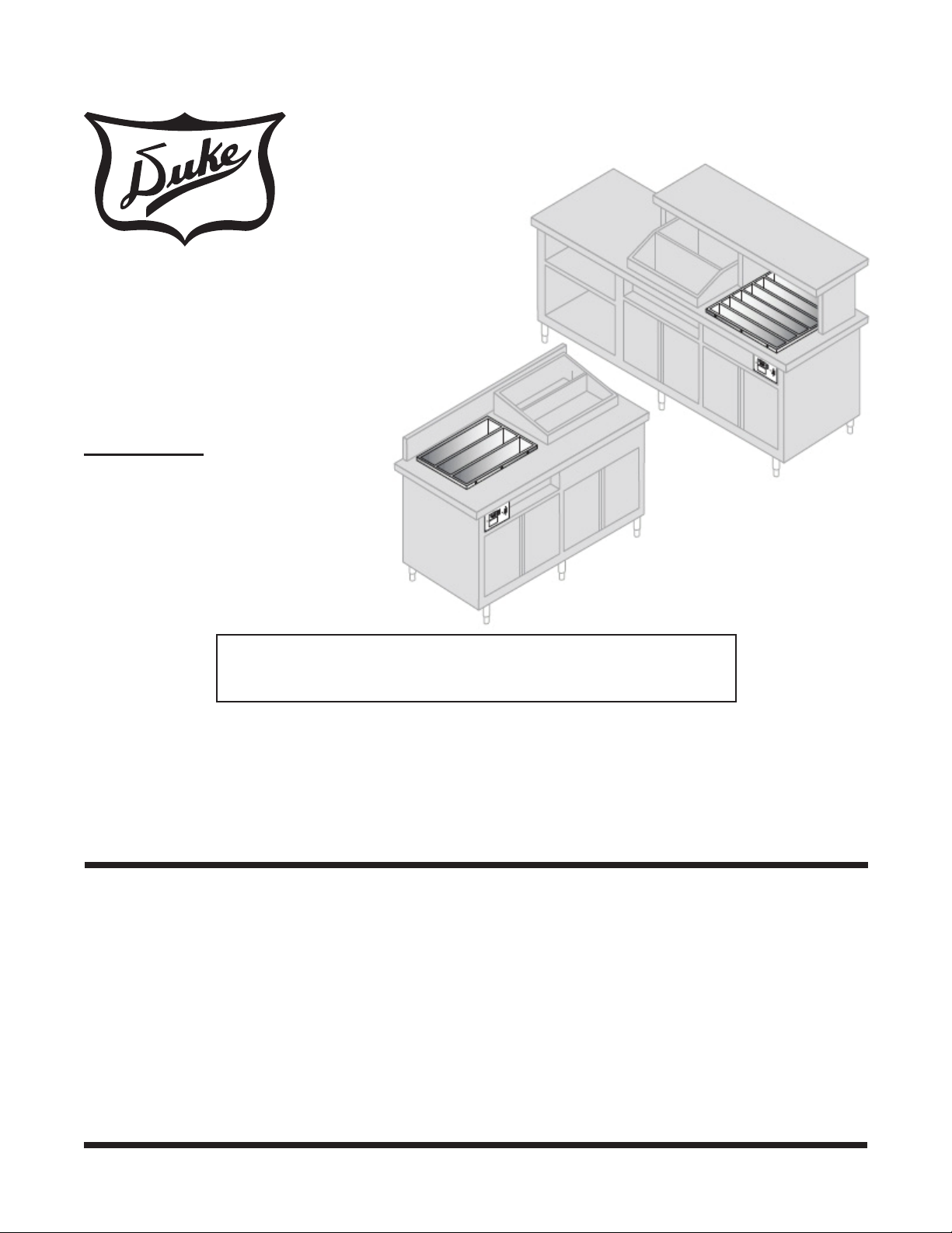
DRY CHANNEL
MODELS
HDC3/HDC6
Service Manual
Please read this manual completely before attempting
to install, operate or service this equipment
This document is prepared for trained Duke service technicians. It is not to be used by anyone not
properly qualied to perform these procedures.
This Service Manual is not all encompassing. If you have not been trained on servicing this product,
be sure to read the manual completely before attempting servicing. Be sure all necessary tools, test
equipment, and skills are available. Those procedures for which you do not have the proper skills
and test equipment must be performed only by a qualied Duke trained service technician.
This manual is Copyright © 2011 Duke Manufacturing Company. All rights reserved.
Reproduction without written permission is prohibited. Duke is a registered
trademark of the Duke Manufacturing Company.
Duke Manufacturing Company
2305 N. Broadway
St. Louis, MO 63102
Phone: 314-231-1130
Toll Free: 1-800-735-3853
Fax: 314-231-5074
www.dukemfg.com
P/N 219217B
Service Manual for Dry Channel HDC3/HDC6 Units
IMPORTANT WARNING AND SAFETY INFORMATION
WARNING
READ THIS MANUAL THOROUGHLY BEFORE OPERATING, INSTALLING, OR
PERFORMING MAINTENANCE ON THE EQUIPMENT.
WARNING
FAILURE TO FOLLOW INSTRUCTIONS IN THIS MANUAL CAN CAUSE PROPERTY
DAMAGE, INJURY OR DEATH.
WARNING
DO NOT STORE OR USE GASOLINE OR OTHER FLAMMABLE VAPORS OR
LIQUIDS IN THE VICINITY OF THIS OR ANY OTHER APPLIANCE.
WARNING
DO NOT OPERATE THIS EQUIPMENT WITHOUT PROPERLY PLACING AND
SECURING ALL COVER AND ACCESS PANELS.
CAUTION
Observe the following:
• Provide and maintain adequate minimum clearances from all walls and combustible materials.
• Provide and maintain adequate clearance for air openings.
• Keep the equipment area free and clear of combustible material.
• Operate equipment only on the type of electricity indicated on the specication plate.
• Retain this manual for future reference.
2

Service Manual for Dry Channel HDC3/HDC6 Units
TABLE OF CONTENTS
IMPORTANT SAFETY INSTRUCTIONS ...........................................................................2
INTRODUCTION ...............................................................................................................4
GENERAL ....................................................................................................................4
MODEL DESIGNATIONS ............................................................................................5
MAIN FEATURES .............................................................................................................. 6
RELAY BOX .................................................................................................................6
CONTROL DISPLAY ...................................................................................................6
COMPONENT REPLACEMENT .......................................................................................7
TOOLS REQUIRED.....................................................................................................7
CONTROL DISPLAY ...................................................................................................7
CONTROL BOARD OR MYLAR COVER .................................................................... 7
RELAY BOX .................................................................................................................8
Main Power On/Off Switch ....................................................................................8
Solid State Relays .................................................................................................9
24 Volt Step-Down Transformer ........................................................................... 9
CHANNEL ASSEMBLY .............................................................................................. 10
TESTING AND TROUBLESHOOTING ........................................................................... 11
COMPONENT TESTING ........................................................................................... 11
Primary Power Check .......................................................................................... 11
Fault Conditions ................................................................................................... 11
24 Volt Step-Down Transformer ..........................................................................12
Heater Element and Hi-Limit Thermostat ............................................................12
RTD ...........................................................................................................................13
SEQUENCE OF OPERATION ........................................................................................14
TROUBLESHOOTING CHART ....................................................................................... 15
WIRING DIAGRAM .........................................................................................................16
3
Service Manual for Dry Channel HDC3/HDC6 Units
On/O
Function Control
Button
Select
Buttons
DISPLAYDISPLAY
HEAT ON
READY
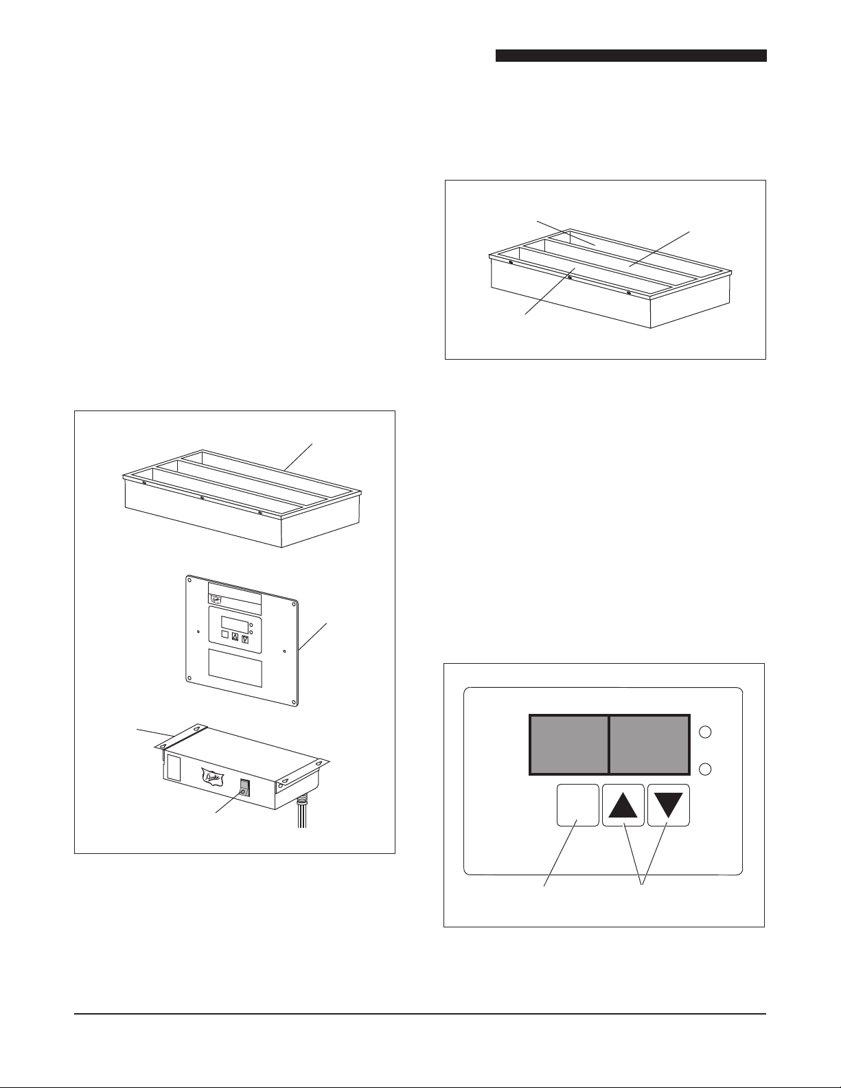
Relay
Box
Display
Box
I
DRY CHANNEL TEMPERATURE
PROG
Tub
Main Power
ON/OFF Switch
Channel 3
Zones 3A & 3B
Channel 1
Zones 1A & 1B
Channel 2
Zones 2A & 2B
INTRODUCTION
GENERAL
The Duke HDC3 Dry Channel unit maintains the
factory set point temperature on 3 channels (front,
back, and center). The Duke HDC6 Dry Channel
unit maintains the factory set point temperature
on 6 channels. Each channel has an A and B
zone. The Main Power On/Off Switch is located
on the Relay/Control Box (herein after referred to
as Relay Box). A display panel will cycle through
the temperature of each channel followed by fault
messages if a fault is detected.
The display temperature will be the average of
the two zones.
Figure 2. Channels and Zones
Pressing the ON button on the Control Display
activates the display. Pressing the up arrow
will cycle through the six temperature zones,
displaying the actual temperatures. Pressing
the down arrow will cycle through the set point
temperature for each channel. The factory set
point temperature is 275°F. The HEAT ON LED
will indicate an activated relay in any zone. The
READY LED is activated when all zones reach
the set point temperature. A fault message will
be displayed to indicate any zone that does
not reach the set point temperature within 45
minutes of power up.
4
Figure 1. Dry Channel Major Components
Figure 3. Control Display

Service Manual for Dry Channel HDC3/HDC6 Units
MODEL DESIGNATIONS
The following chart lists the different model designations and provides information on the weight and
electrical requirements.
TABLE 1. MODEL SPECIFICATIONS
MODEL NO. SHIPPING WT. ELECTRICAL SPECIFICATIONS
HDC3-37.5-208 160 lbs (59.7 kg) 208VAC, 10.1A, 2100W, 50/60Hz
HDC-37.5-240 160 lbs (59.7 kg) 240VAC 8.8A, 2100W, 50/60Hz
HDC6-37.5-208 315 lbs (117.6 kg) 208VAC, 20.1A, 4200W, 50/60Hz
HDC6-37.5-240 315 lbs (117.6 kg) 240VAC, 17.5A, 4200W, 50/60Hz
5
Service Manual for Dry Channel HDC3/HDC6 Units
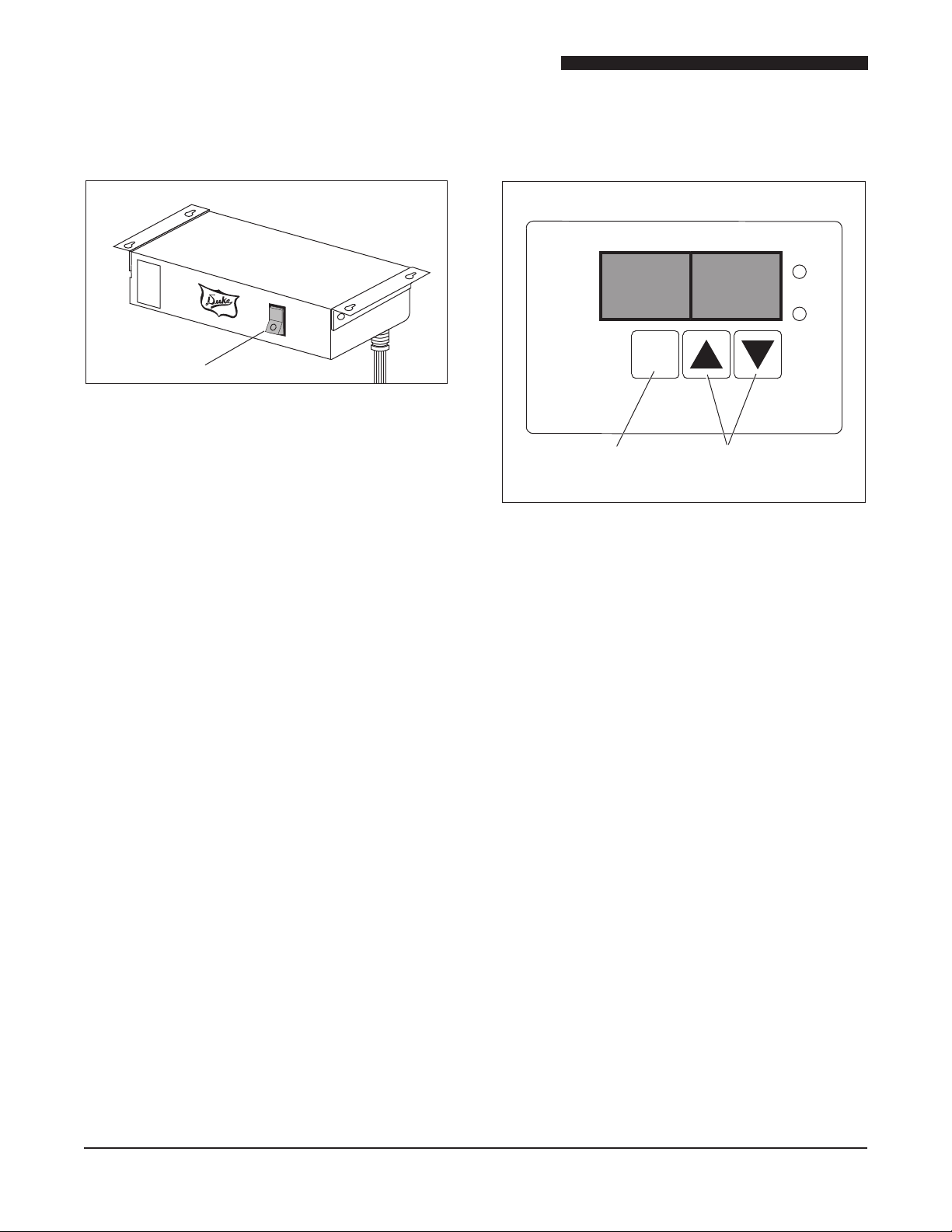
Main Power
On/Off Switch
I
On/O
Function Control
Button
Select
Buttons
DISPLAYDISPLAY
HEAT ON
READY
MAIN FEATURES
RELAY BOX
Figure 4. Relay Box
The Main Power On/Off Switch is located on
the lower right side of the Relay Box. This is a
lighted double pull single throw (DPST) switch
rated at 20 Amperes. The Relay Box houses a 24
Volt Step-Down Transformer and six Solid State
Relays (SSR).
CONTROL DISPLAY
Figure 5. Control Display
The display provides a readout of actual
temperature, set point temperature and fault
conditions.
The control board inside the Control Display
maintains the temperature of all three channels.
Each channel has an A & B zone. The control board
monitors each zone’s temperature and activates a
relay to supply power to the heater for that zone.
When the ON/OFF button is pressed, the display
cycles through the temperature of each channel.
If a fault is detected, the fault code is displayed.
The displayed temperature will be the average of
the two zones associated with that channel.
6
 Loading...