

Duke FWM3-42 User Manual
Operation Manual
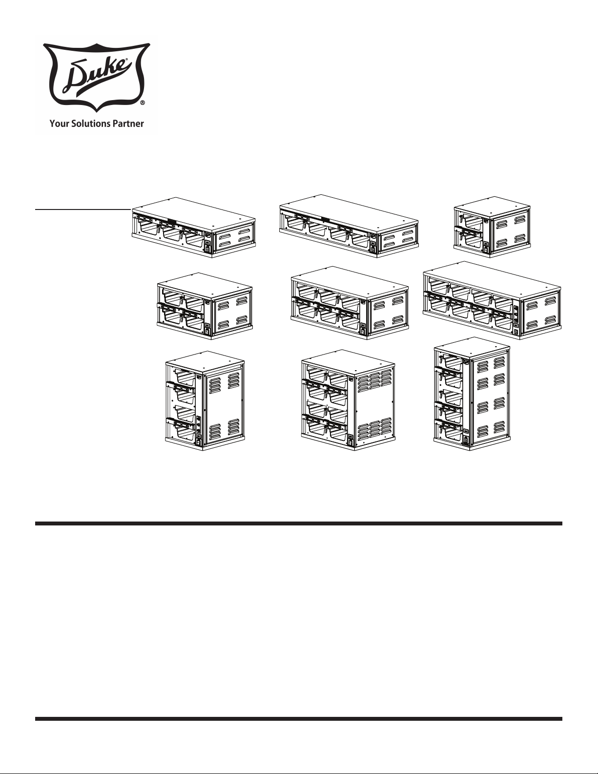
PRODUCT HOLDING CABINET
MODELS
FWM3-13
FWM3-14
FWM3-21
FWM3-22
FWM3-23
FWM3-24
Installation and
FWM3-41
FWM3-42
FWM3-51
Please read this manual completely before attempting
to install, operate or service this equipment
This manual is Copyright © 2018 Duke Manufacturing Co. All rights reserved.
Reproduction without written permission is prohibited. Duke is a registered
trademark of the Duke Manufacturing Co.
Duke Manufacturing Co.
2305 N. Broadway
St. Louis, MO 63102
Phone: 314-231-1130
Toll Free: 1-800-735-3853
Fax: 314-231-5074
www.dukemfg.com
P/N 156237
REV Y 4/20/2018

Installation and Operation of Product Holding Cabinets
2

Installation and Operation of Product Holding Cabinets
TABLE OF CONTENTS
ELECTRICAL WARNINGS ................................................................................................ 4
MANUFACTURER’S INTRODUCTION .............................................................................6
SPECIFICATIONS ............................................................................................................. 7
Model FWM3-13 ......................................................................................................... 7
Model FWM3-14 ......................................................................................................... 8
Model FWM3-21 ......................................................................................................... 9
Model FWM3-22 ....................................................................................................... 10
Model FWM3-23 ....................................................................................................... 11
Model FWM3-24 ....................................................................................................... 12
Model FWM3-41 ....................................................................................................... 13
Model FWM3-42 ....................................................................................................... 14
Model FWM3-51 ....................................................................................................... 15
INSTALLATION INSTRUCTIONS ...................................................................................16
Stacking Units ..........................................................................................................17
OPERATION ....................................................................................................................18
OPENING CHECKLIST .......................................................................................... 18
OPERATION INSTRUCTIONS AND ADJUSTMENTS ........................................18
CLOSING CHECKLIST ..........................................................................................18
CLEANING INSTRUCTIONS .................................................................................18
STAINLESS STEEL CARE .......................................................................................18
KEYPAD PROGRAMMING .............................................................................................19
Power Up .................................................................................................................. 19
Timer Operation ........................................................................................................20
Time Decrement .......................................................................................................20
Menu Mode ..............................................................................................................21
WEB PROGRAMMING ..................................................................................................22
Creating A New Program ..........................................................................................22
Revising A Cabinet Setting .......................................................................................25
TROUBLESHOOTING ....................................................................................................26
Electronic Control Fault Indications .......................................................................... 26
Temperature Check Procedure ................................................................................26
Service Hot-Line ....................................................................................................... 26
PARTS LISTS AND ILLUSTRATIONS .........................................................................28
WIRING SCHEMATICS ............................................................................................32-37
TABLE MOUNTING (5X1) .............................................................................................38
3

Installation and Operation of Product Holding Cabinets
ELECTRICAL WARNINGS
THIS MANUAL HAS BEEN PREPARED FOR PERSONNEL QUALIFIED TO INSTALL
ELECTRICAL EQUIPMENT, WHO SHOULD PERFORM THE INITIAL FIELD STARTUP
AND ADJUSTMENTS OF THE EQUIPMENT COVERED BY THIS MANUAL.
READ THIS MANUAL THOROUGHLY BEFORE OPERATING, INSTALLING OR PERFORMING
MAINTENANCE ON THE EQUIPMENT.
: Failure to follow all the instructions in this manual can cause
property damage, injury or death.
: Improper installation, adjustment, alteration, service or maintenance
can cause property damage, injury or death.
: (US/CAN ONLY) Electrical connections should be performed only by
a certied professional.
: Electrical and grounding connections must comply with the applicable
portions of the National Electric Code and/or all local electric codes. Failure to
comply with this procedure can cause property damage, injury or death.
: Before connecting the unit to the electrical supply, verify that the
electrical and grounding connections comply with the applicable portions of the
National Electric Code and/or other local electrical codes. Failure to comply with
this procedure can cause property damage, injury or death.
: Before connecting the unit to the electrical supply, verify that the
electrical connection agrees with the specications on the data plate. Failure to
comply with this procedure can cause property damage, injury or death.
: UL73 grounding instructions: This appliance must be connected to
a grounded, metal, permanent wiring system. Or an equipment-grounding conductor
must be run with the circuit conductors and connected to the equipment-grounding
terminal or lead on the appliance. Failure to comply with this procedure can cause
property damage, injury or death.
: Appliances equipped with a exible electric supply cord, are
provided with a three-prong grounding plug. It is imperative that this plug be
connected into a properly grounded three-prong receptacle. Failure to comply with
this procedure can cause property damage, injury or death.
: If the receptacle is not the proper grounding type, contact an
electrician. Do not remove the grounding prong from the plug. Failure to comply
with this procedure can cause property damage, injury or death.
4

Installation and Operation of Product Holding Cabinets
: Before performing any service that involves electrical connection
or disconnection and/or exposure to electrical components, always perform the
Electrical LOCKOUT/TAGOUT Procedure. Disconnect all circuits. Failure to comply
with this procedure can cause property damage, injury or death.
: Before removing any sheet metal panels or servicing this
equipment, always perform the Electrical LOCKOUT/TAGOUT Procedure. Be sure
all circuits are disconnected. Failure to comply with this procedure can cause
property damage, injury or death.
: Do not operate this equipment without properly placing and
securing all covers and access panels. Failure to comply with this procedure
can cause property damage, injury or death.
: For your safety, do not use or store gasoline or other ammable
vapors or liquids in the vicinity of this or any other appliance. Failure to
comply can cause property damage, injury or death.
: In the event of a power failure, do not attempt to operate this
appliance. Failure to comply can cause property damage, injury or death.
: This appliance is not intended for use by persons (including
children) with reduced physical, sensory or mental capabilities, or lack of
experience and knowledge, unless they have been given supervision or
instruction concerning use of the appliance by a person responsible for their
safety. Children should be supervised to ensure they do not play with the
appliance.
: It is recommended that children be supervised to ensure that
they are not playing with the appliance.
: If the power cord is damaged, it must be replaced by the
manufacturer or authorized agent or qualied person in order to avoid a hazard.
CAUTION
Observe the following:
• Minimum clearances must be maintained from all walls and combustible materials.
• Keep the equipment area free and clear of combustible material.
• Maintain adequate clearance for air openings.
• Operate equipment only on the type of electricity indicated on the data sticker.
• Retain this manual for future reference.
5
Installation and Operation of Product Holding Cabinets
MANUFACTURER’S INTRODUCTION
The Duke Product Holding Unit was developed for extended food-holding capabilities to provide consistently high,
“just cooked” food quality.
The Duke Product Holding Unit utilizes Duke’s patented “heat sink” holding technology that provides even heat
distribution to food pans through the bottom and sides. This allows pre-cooked foods to be held for extended periods
without noticeable degradation of quality, reducing food scrap/waste.
The self contained, individually formed, sealed compartments of the Duke Product Holding Unit eliminates food odor
and taste transfer. Because the compartments are sealed and formed to the shape of the pan, no disassembly is
required for cleaning and product changes.
The unique design of the Duke Product Holding Unit allows single temperature operation for all existing product
groups. This 180°F(82°C) approved temperature is preset at the factory. This reduces the likelihood of inconsistent
performance between restaurant locations.
The Duke Product Holding Cabinet was also designed to rethermalize food product. A thermostat setting of 180°F(82°C)
minimum is required for re-thermalization. To comply with sanitation requirements do not set the temperature control
lower than 180°F(82°C) or equivalent.
: Only qualied service persons should modify control temperature presets.
SERIAL NUMBER LOCATION
The Serial Number Data Label is located on the rear of the unit, above the power cord connection. Refer to the Serial
Number Data Label for proper electrical requirements. The serial number and model number are required when
communicating with the Duke Service Department.
6
Installation and Operation of Product Holding Cabinets
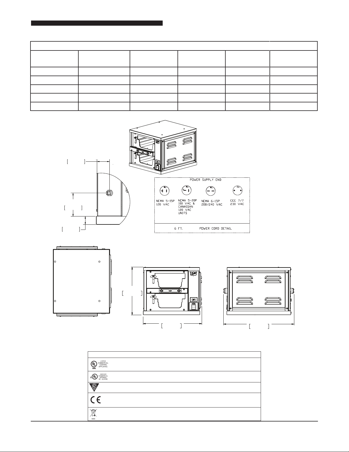
SPECIFICATIONS
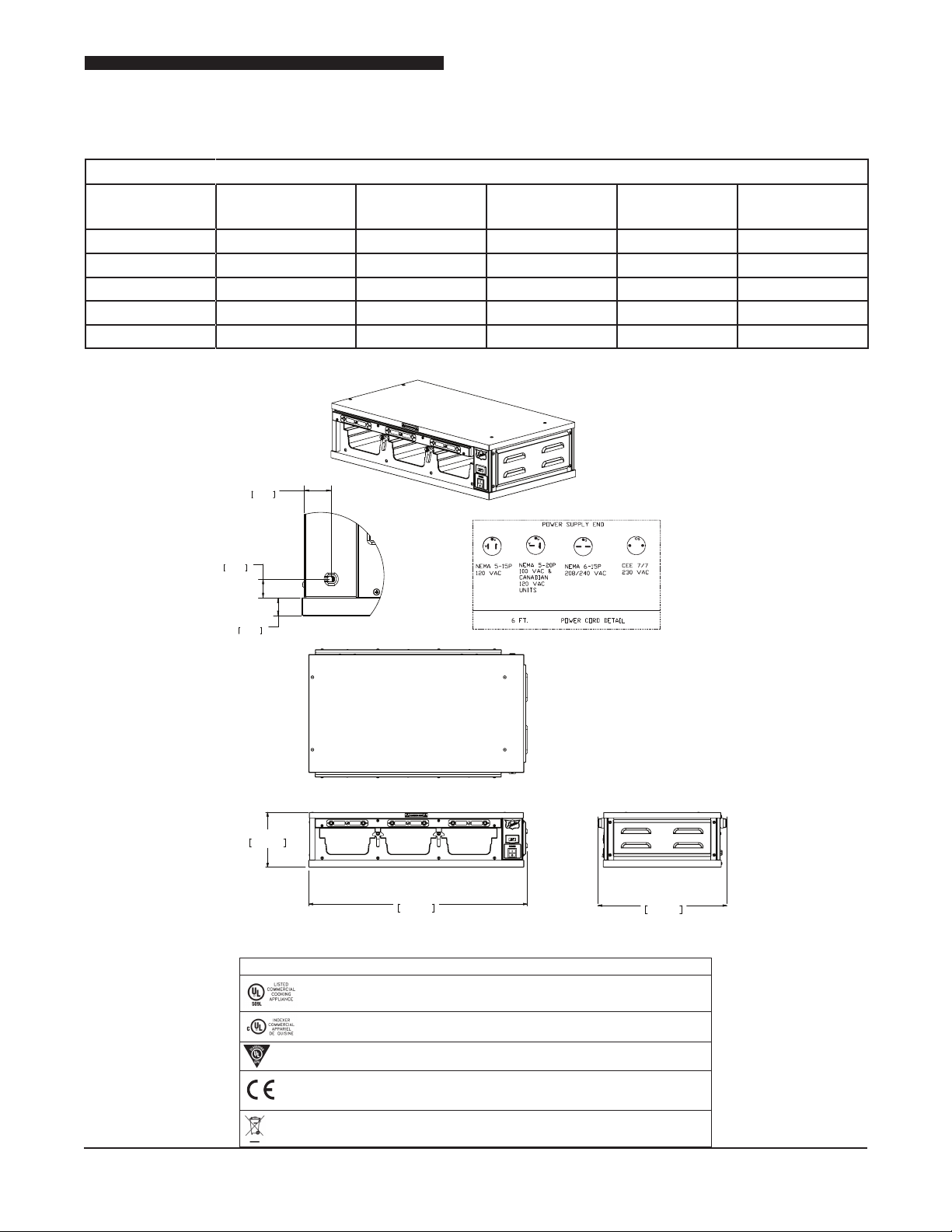
MODEL FWM3-13
MODEL SHIPPING
WEIGHT
FWM3-13-100 75 lbs (34,1Kg) 100 600 6.0 (6,0) 60
FWM3-13-120 75 lbs (34,1Kg) 120 600 5.0 (5,0) 60
FWM3-13-208 75 lbs (34,1Kg) 208 900 4.0 (4,0) 60
FWM3-13-230 75 lbs (34,1Kg) 230 900 4.0 (4,0) 50
FWM3-13-240 75 lbs (34,1Kg) 240 900 4.0 (4,0) 60
1 3/8”
3,6 cm
AC Voltage
(V)
Watts
(W)
Amps
(A)
FREQUENCY
(Hz)
2,5 cm
1”
2,5 cm
1”
7 3/8"
18.720cm
(US) (US/CAN)
(182,9cm)
TOP
29 3/8"
74,458 cm
(GERMANY,
FRANCE AND
UK CE UNITS)
17 1/4"
43,970 cm
ENDFRONT
Compliance Declaration
Standard: UL197 File: KNGT.E17421
Standard: CSA-C22.2 No. 109 File: KNGT7.E17421
Standard: ANSI / NSF 4 File: TSQT.E157479
Directive 2014/35/EU:
EN60335 -1:2002, A1, A2, A11, A12
EN 60335-2-49:2003
WEEE RoHS Directive 2002/96/EC
Directive 89/336/EEC and 2014/30/EU:
EN61000-3-2 EN 55014-1
EN61000-3-3 EN55014-2
7
Installation and Operation of Product Holding Cabinets
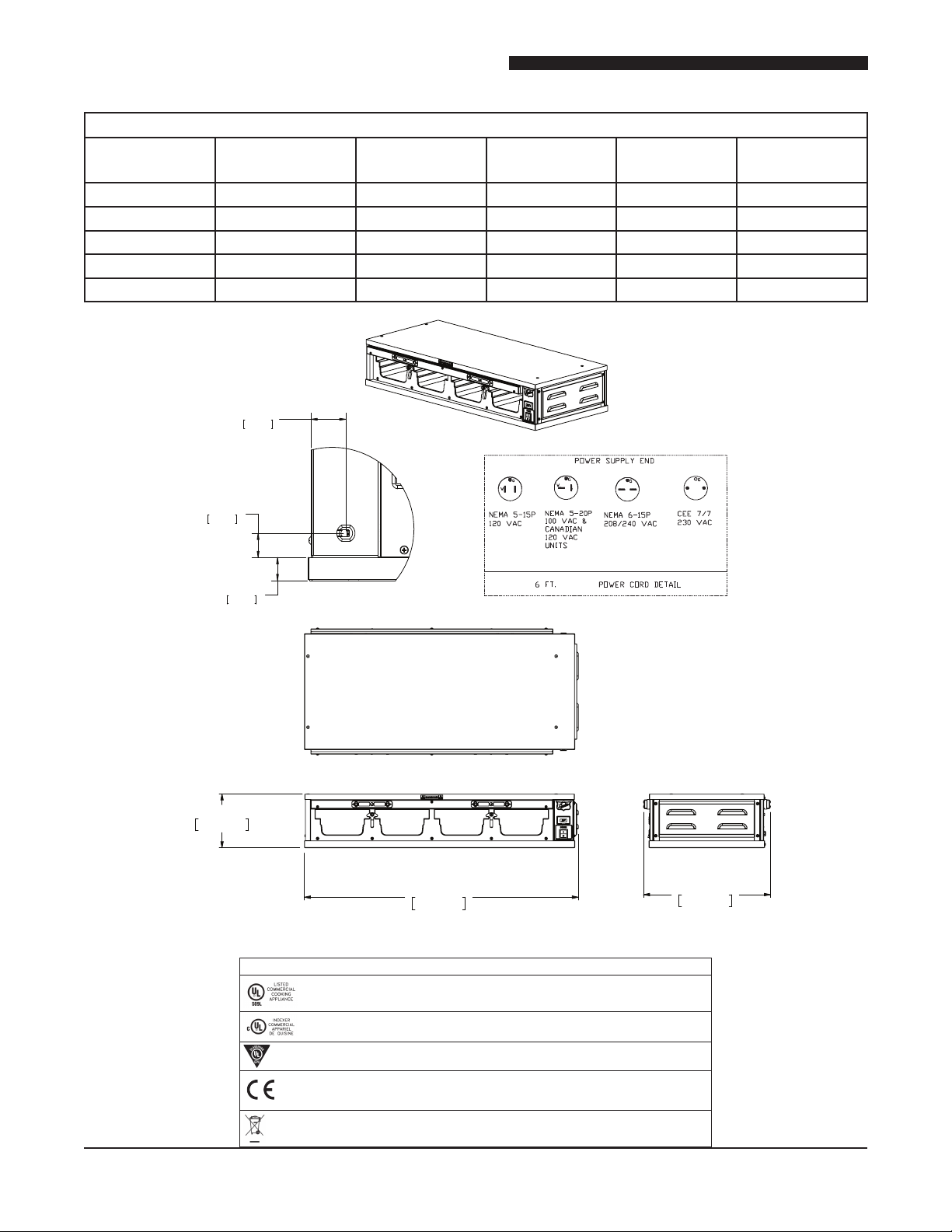
MODEL FWM3-14
MODEL SHIPPING
WEIGHT
FWM3-14-100 111 lbs (50,5Kg) 100 800 8.0 (8,0) 60
FWM3-14-120 111 lbs (50,5Kg) 120 800 7.0 (7,0) 60
FWM3-14-208 111 lbs (50,5Kg) 208 1200 6.0 (6,0) 60
FWM3-14-230 111 lbs (50,5Kg) 230 1200 5.0 (5,0) 50
FWM3-14-240 111 lbs (50,5Kg) 240 1200 5.0 (5,0) 60
1 3/8”
3,6 cm
1”
2,5 cm
AC Voltage
(V)
Watts
(W)
(US) (US/CAN)
Amps
(A)
(GERMANY,
FRANCE AND
UK CE UNITS)
FREQUENCY
(Hz)
7 3/8"
18.720cm
1”
2,5 cm
(182,9cm)
TOP
37 1/2"
95,176 cm
44,122 cm
17 3/8"
ENDFRONT
Compliance Declaration
Standard: UL197 File: KNGT.E17421
Standard: CSA-C22.2 No. 109 File: KNGT7.E17421
Standard: ANSI / NSF 4 File: TSQT.E157479
Directive 2014/35/EU:
EN60335 -1:2002, A1, A2, A11, A12
EN 60335-2-49:2003
WEEE RoHS Directive 2002/96/EC
Directive 89/336/EEC and 2014/30/EU:
EN61000-3-2 EN 55014-1
EN61000-3-3 EN55014-2
8
Installation and Operation of Product Holding Cabinets
MODEL FWM3-21
MODEL SHIPPING
WEIGHT
FWM3-21-100 67 lbs (30,5Kg) 100 400 4.0 (4,0) 60
FWM3-21-120 67 lbs (30,5Kg) 120 400 4.0 (4,0) 60
FWM3-21-208 67 lbs (30,5Kg) 208 600 3.0 (3,0) 60
FWM3-21-230 67 lbs (30,5Kg) 230 600 3.0 (3,0) 50
FWM3-21-240 67 lbs (30,5Kg) 240 600 3.0 (3,0) 60
1 3/8”
3,6 cm
AC Voltage
(V)
Watts
(W)
Amps
(A)
FREQUENCY
(Hz)
2 3/4”
6,9 cm
1 ”
2,5 cm
(US) (US/CAN)
(182,9cm)
11 3/4"
29,903 cm
14 1/2"
36,680 cm
Compliance Declaration
Standard: UL197 File: KNGT.E17421
(GERMANY,
FRANCE AND
UK CE UNITS)
17 3/8"
44,129cm
ENDFRONTTOP
Standard: CSA-C22.2 No. 109 File: KNGT7.E17421
Standard: ANSI / NSF 4 File: TSQT.E157479
Directive 2014/35/EU:
EN60335 -1:2002, A1, A2, A11, A12
EN 60335-2-49:2003
WEEE RoHS Directive 2002/96/EC
Directive 89/336/EEC and 2014/30/EU:
EN61000-3-2 EN 55014-1
EN61000-3-3 EN55014-2
9
Installation and Operation of Product Holding Cabinets
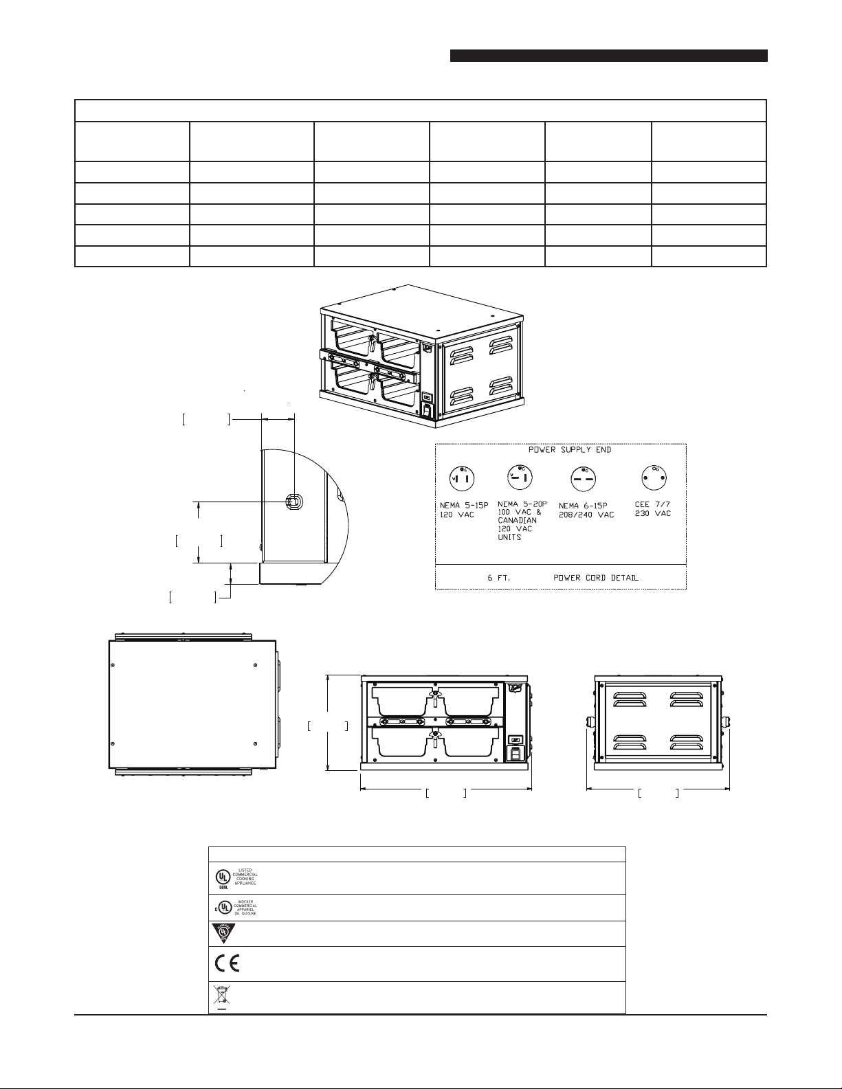
MODEL FWM3-22
MODEL SHIPPING
WEIGHT
FWM3-22-100 91 lbs (41,4Kg) 100 800 8.0 (8,0) 60
FWM3-22-120 91 lbs (41,4Kg) 120 800 7.0 (7,0) 60
FWM3-22-208 91 lbs (41,4Kg) 208 1200 6.0 (6,0) 60
FWM3-22-230 91 lbs (41,4Kg) 230 1200 5.0 (5,0) 50
FWM3-22-240 91 lbs (41,4Kg) 240 1200 5.0 (5,0) 60
1 3/8”
3,6 cm
AC Voltage
(V)
Watts
(W)
Amps
(A)
FREQUENCY
(Hz)
2 3/4”
6,9 cm
1 ”
2,5 cm
(US) (US/CAN)
(182,9cm)
11 3/4"
29,840 cm
Compliance Declaration
Standard: UL197 File: KNGT.E17421
Standard: CSA-C22.2 No. 109 File: KNGT7.E17421
21 1/8"
53,729 cm
(GERMANY,
FRANCE AND
UK CE UNITS)
17 5/8"
44,914 cm
ENDFRONTTOP
10
Standard: ANSI / NSF 4 File: TSQT.E157479
Directive 2014/35/EU:
EN60335 -1:2002, A1, A2, A11, A12
EN 60335-2-49:2003
WEEE RoHS Directive 2002/96/EC
Directive 89/336/EEC and 2014/30/EU:
EN61000-3-2 EN 55014-1
EN61000-3-3 EN55014-2
Installation and Operation of Product Holding Cabinets
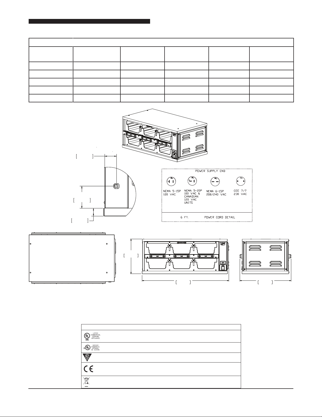
MODEL FWM3-23
MODEL SHIPPING
WEIGHT
FWM3-23-100 113 lbs (51,4Kg) 100 1200 12.0 (12,0) 60
FWM3-23-120 113 lbs (51,4Kg) 120 1200 10.0 (10,0) 60
FWM3-23-208 113 lbs (51,4Kg) 208 1800 9.0 (9,0) 60
FWM3-23-230 113 lbs (51,4Kg) 230 1800 8.0 (8,0) 50
FWM3-23-240 113 lbs (51,4Kg) 240 1800 8.0 (8,0) 60
1 3/8”
3,6 cm
AC Voltage
(V)
Watts
(W)
Amps
(A)
FREQUENCY
(Hz)
2 3/4”
6,9 cm
1 ”
2,5 cm
(US) (US/CAN)
(182,9cm)
Standard: UL197 File: KNGT.E17421
Standard: CSA-C22.2 No. 109 File: KNGT7.E17421
11 3/4"
29,840 cm
Compliance Declaration
29 1/4"
74,447 cm
(GERMANY,
FRANCE AND
UK CE UNITS)
17 3/8"
43,976 cm
ENDFRONTTOP
Standard: ANSI / NSF 4 File: TSQT.E157479
Directive 2014/35/EU:
EN60335 -1:2002, A1, A2, A11, A12
EN 60335-2-49:2003
WEEE RoHS Directive 2002/96/EC
Directive 89/336/EEC and 2014/30/EU:
EN61000-3-2 EN 55014-1
EN61000-3-3 EN55014-2
11
Installation and Operation of Product Holding Cabinets
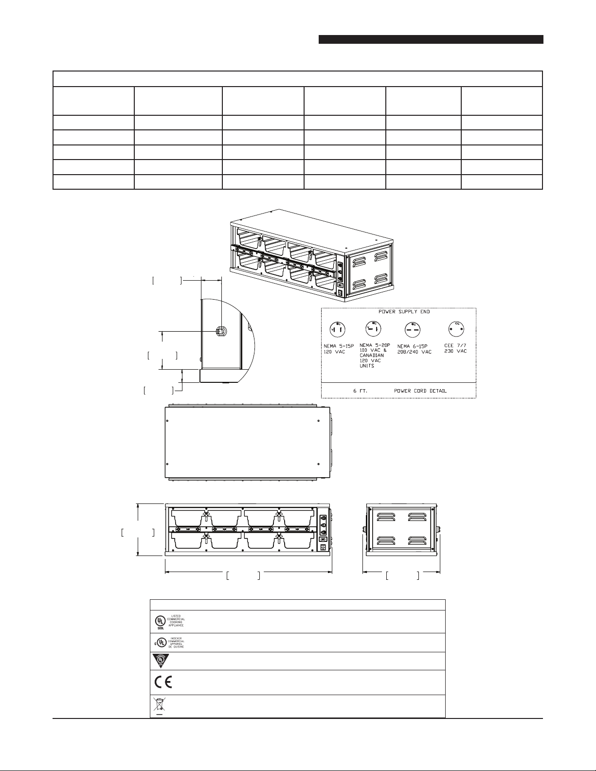
ENDFRONT
MODEL FWM3-24
MODEL SHIPPING
WEIGHT
FWM3-24-100 141 lbs (69,1Kg) 100 1600 16.0 (16,0) 60
FWM3-24-120 141 lbs (69,1Kg) 120 1600 13.0 (13,0) 60
FWM3-24-208 141 lbs (69,1Kg) 208 2400 12.0 (12,0) 60
FWM3-24-230 141 lbs (69,1Kg) 230 2400 10.0 (10,0) 50
FWM3-24-240 141 lbs (69,1Kg) 240 2400 10.0 (10,0) 60
1 3/8”
3,6 cm
AC Voltage
(V)
Watts
(W)
Amps
(A)
FREQUENCY
(Hz)
11 3/4"
29,840 cm
2 3/4”
6,9 cm
1 ”
2,5 cm
(US) (US/CAN)
(182,9cm)
TOP
95,100 cm
Standard: UL197 File: KNGT.E17421
37 1/2"
Compliance Declaration
17 3/8"
43,976 cm
(GERMANY,
FRANCE AND
UK CE UNITS)
12
Standard: CSA-C22.2 No. 109 File: KNGT7.E17421
Standard: ANSI / NSF 4 File: TSQT.E157479
Directive 2014/35/EU:
EN60335 -1:2002, A1, A2, A11, A12
EN 60335-2-49:2003
WEEE RoHS Directive 2002/96/EC
Directive 89/336/EEC and 2014/30/EU:
EN61000-3-2 EN 55014-1
EN61000-3-3 EN55014-2
 Loading...