

Page 1

DUKANE CORPORATION
SEACOM DIVISION
TECHNICAL MANUAL
UNDERWATER ACOUSTIC BEACON
MODELS DK100/DK120/DK130/DK140
April 13, 2004
REV 13
DUKANE CORPORATION ST. CHARLES, ILLINOIS 60174 PHONE: 630-762-4050 FAX: 630-762-4049
DOCUMENT NO. 03-TM-0037 © DUKANE CORPORATION
E-MAIL: [email protected] INTERNET: www.dukcorp.com/seacom
03-TM-0037 REV 13
Page 1 of 24
Page 2

This manual should be read in its entirety prior to
any installation, operation, testing or maintenance
of the DK100/DK120/DK130/DK140 Underwater
Acoustic Beacons.
03-TM-0037 REV 13
Page 2 of 24
Page 3

TABLE OF CONTENTS
SECTION I................................................................................................................... 5
GENERAL INFORMATION..................................................................................... 5
1.1. INTRODUCTION........................................................................................................... 5
1.2. GENERAL DESCRIPTION. .......................................................................................... 5
SECTION II ................................................................................................................. 8
INSTALLATION ........................................................................................................ 8
2.1. GENERAL..................................................................................................................... 8
2.2. INSTALLATION CRITERIA OF THE BEACON. .......................................................... 8
2.3. SURVIVABILITY. .......................................................................................................... 8
2.4. ENVIRONMENTAL. ...................................................................................................... 8
2.5. MAINTENANCE............................................................................................................ 8
2.6. INSTALLATION PROCEDURES FOR THE DK100/DK120 AND THE N30A26 SE-
RIES MOUNTING KIT. ................................................................................................... 9
2.7. INSTALLATION PROCEDURES FOR THE DK100/DK120 AND THE N30A21A
MOUNTING KIT............................................................................................................ 10
2.8. INSTALLATION PROCEDURES FOR THE DK130/DK140 AND THE N30A29 SE-
RIES MOUNTING KIT. ................................................................................................. 12
2.9. INSTALLATION PROCEDURES FOR THE DK130/DK140 AND THE N30A21A
MOUNTING KIT............................................................................................................ 13
SECTION III ............................................................................................................. 15
OPERATION.............................................................................................................15
3.1. THEORY OF OPERATION. ........................................................................................ 15
SECTION IV.............................................................................................................. 16
TESTING ................................................................................................................... 16
4.1. GENERAL................................................................................................................... 16
4.3. OPERATIONAL TESTING.......................................................................................... 16
SECTION V ...............................................................................................................17
MAINTENANCE DK100/DK130 ............................................................................17
5.1. GENERAL................................................................................................................... 17
5.2. BEACON CLEANING. ................................................................................................ 17
5.3. BEACON TESTING. ................................................................................................... 17
5.4. PRECAUTIONS. ......................................................................................................... 17
5.5. BATTERY. .................................................................................................................. 17
5.6. BEACON DISPOSAL. ................................................................................................ 17
5.7. BEACON STORAGE. ................................................................................................. 17
SECTION VI.............................................................................................................. 18
MAINTENANCE DK120/DK140 ............................................................................18
6.1. GENERAL................................................................................................................... 18
6.2. BEACON CLEANING. ................................................................................................ 18
6.3. BEACON TESTING. ................................................................................................... 18
6.4. PRECAUTIONS. ......................................................................................................... 18
6.5. BEACON DISASSEMBLY.......................................................................................... 18
03-TM-0037 REV 13
Page 3 of 24
Page 4

6.6. BATTERY REPLACEMENT AND TESTING.............................................................. 18
6.7. BEACON OFF-CURRENT TEST................................................................................ 21
6.8. BATTERY DISPOSAL. ............................................................................................... 21
6.9. BEACON STORAGE. ................................................................................................. 21
6.10. BEACON OVERHAUL.............................................................................................. 21
SECTION VII ............................................................................................................ 22
WARRANTY DK100/DK120/DK130/DK140 ........................................................ 22
SECTION VIII...........................................................................................................23
SERVICE PROGRAM DK100/DK120/DK130/DK140 ......................................... 23
8.1. BEACON RETURN – DEFECTIVE............................................................................. 23
8.2. BEACON RETURN - NO DEFECT. ............................................................................ 23
8.3. BEACON RETURN - OUT OF WARRANTY. ............................................................. 23
8.4. BATTERY CHANGE/OVERHAUL FOR THE DK100 & DK130. ................................ 2 3
SECTION IX.............................................................................................................. 24
PROCEDURE FOR RETURNING DK SERIES BEACON TO FACTORY ..... 24
9.1. BEACON SERVICE. ................................................................................................... 24
9.2. BATTERY CHANGE/OVERHAUL.............................................................................. 24
TABLE OF FIGURES
Figure 1. DK Series Underwater Acoustic Beacon Installed in Mounting Kits ............. 5
Figure 2. Water Switch Location on Beacon.................................................................... 5
Figure 3. N30A26 Series Mounting Kit Installation Details............................................. 9
Figure 4. Installation of N30A26 Series Mounting Kit and Beacon .............................. 10
Figure 5. Mounting Hole Template for N30A21A Mounting Kit .................................... 10
Figure 6. N30A21A Mounting Kit and Beacon Overall Dimensions ............................. 11
Figure 7. Method of Installing the N30A21A Mounting Kit............................................ 11
Figure 8. Securing Beacon in N30A21A Mounting Kit .................................................. 11
Figure 9. N30A29 Mounting Kit Installation Details....................................................... 12
Figure 10. Installation of N30A29 Series Mounting Kit and Beacon ............................ 13
Figure 11. Mounting Hole Template for N30A21A Mounting Kit .................................. 13
Figure 12. N30A21A Mounting Kit and Beacon Overall Dimensions ........................... 14
Figure 13. Method of Installing the N30A21A Mounting Kit.......................................... 14
Figure 14. Securing Beacon In N30A21A Mounting Kit ................................................ 14
Figure 15. Nominal Pulse Train....................................................................................... 15
Figure 16. Typical Beacon Label..................................................................................... 16
Figure 17. Beacon Voltage Code .................................................................................... 16
Figure 18. Battery End Cover Removal With Vise Clamp and Spanner Wrench ........ 19
FIGURE 19. Battery Kit..................................................................................................... 19
Figure 20. Beacon Exploded View Showing Relative Location of Battery and Related
Parts............................................................................................................................. 20
Figure 21. RBB Label Placement ................................................................................... 21
Figure 22. Beacon Off-Current Test Set-Up ................................................................... 21
03-TM-0037 REV 13
Page 4 of 24
Page 5
SECTION I
GENERAL INFORMATION
1.1. INTRODUCTION.
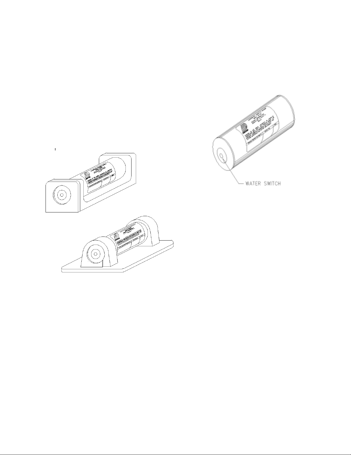
1.1.1. GENERAL. This manual contains the de-
scription, theory, installation and maintenance for
the DK100/DK120/DK130/DK140 Underwater
Acoustic Beacon, hereafter referred to as the “DK
Series”, manufactured by Dukane Corporation,
Seacom Division, 2900 Dukane Drive, St. Charles,
Illinois, 60174. See Figures 1 and 2. These beacons have been tested to, and meet, or exceed, all
requirements of FAA TSO-C121.
shock and deep-water immersion. As shown on
page 6 and 7, the DK Series beacons operate for
30 days when immersed in water. See Figure 2.
Figure 2. Water Switch Location on
Beacon
Figure 1. DK Series Underwater
Acoustic Beacon Installed in
Mounting Kits
1.1.2. SYMBOLS AND ABBREVIATIONS.
Symbols and abbreviations used in this manual are
in accordance with ANSI Y14.15 and MIL-STD12, respectively.
1.2. GENERAL DESCRIPTION.
1.2.1. PHYSICAL CHARACTERISTICS. The
DK Series beacons consist of a self-contained
battery, an electronic module and a transducer. It
is housed in a cylindrical watertight aluminum
case capable of withstanding high-G impact
1.2.2. BEACON MOUNTING. The beacon is
mounted to a flight recorder or the airframe by
means of a mounting kit (See Section II). This
mount consists of an extruded channel, which in
conjunction with a securing plate retains the beacon. Figure 1 shows the beacon mounted in the
N30A21A Mounting Kit, a strap-type mount. This
mount is used for applications where space limitations do not permit the use of the simpler N30A26
Series cradle mount.
1.2.3. BEACON SIGNAL. The beacon is a battery-powered device, which radiates a pulsed
acoustic signal into the surrounding water upon
activation by its water-sensitive switch. Search
operations in water for beacon equipped aircraft
can be conducted by utilizing a portable receiver
equipped with a directional hydrophone such as
the Dukane Model N30A5 Series Locator. This
receiver system is operable from small boats or by
free-swimming SCUBA divers. Aircraft lost in
deep water, i.e., in excess of 6000 feet (1829
meters), require special search gear. Beacon Specifications are listed on page 6 and 7.
03-TM-0037 REV 13
Page 5 of 24
Page 6

DK100/DK120 BEACON SPECIFICATIONS
Operating Freuency...............................................
Operating Depth....................................................
Pulse Length.........................................................
Pulse Repetition Rate............................................
Operating Life.......................................................
Battery Life In Beacon..........................................
Acoustic Output, Initial.........................................
Acoustic Output After 30 Days.............................
Operating Temperature Range..............................
Actuation...............................................................
37.5 kHz ± 1 kHz
Surface to 20,000 feet (6096 meters)
10 milliseconds
+ 10%
Not less than 0.9 Pulse/Sec
30 days (minimum)
6 Years
1060 dynes/cm
2
rms pressure at 1 meter
(160.5dB)
700 dynes/cm2 rms pressure at 1 meter (157.0dB)
+28°F (-2.2°C) to +100°F (+37.8°C)
Fresh or salt water
Radiation Pattern...................................................
Size.........................................................................
Rated output over 80 percent of sphere
1.30 inches (3.30 cm) diameter x 3.92 inches
(9.95 cm) long (less mount)
Weight, Beacon.....................................................
Weight, N30A26B Mount.....................................
Weight, N30A21A Mount....................................
Storage Temperature Range..................................
6.7 ounces (190 grams)
6 ounces (170 grams)
3 ounces (85 grams)
-65°F (-54°C) to 160°F (71°C)
1.2.4. ENVIRONMENTAL TEST. The beacon complies with the preceding operational performance
standards after being subjected to environmental tests specified in FAA TSO-C121.
03-TM-0037 REV 13
Page 6 of 24
Page 7

DK130/DK140 BEACON SPECIFICATIONS
Operating Freuency............................................... 37.5 kHz ± 1 kHz
Operating Depth....................................................
Pulse Length.........................................................
Pulse Repetition Rate............................................
Operating Life.......................................................
Battery Life In Beacon..........................................
Acoustic Output, Initial.........................................
Acoustic Output After 30 Days.............................
Operating Temperature Range..............................
Actuation...............................................................
Radiation Pattern...................................................
Surface to 20,000 feet (6096 meters)
10 milliseconds
+ 10%
Not less than 0.9 Pulse/Sec
30 days (minimum)
6 Years
1060 dynes/cm
2
rms pressure at 1 meter
(160.5dB)
700 dynes/cm2 rms pressure at 1 meter (157.0dB)
+28°F (-2.2°C) to +100°F (+37.8°C)
Fresh or salt water
Rated output over 80 percent of sphere
Size.........................................................................
1.30 inches (3.30 cm) diameter x 2.97 inches
(7.54 cm) long (less mount)
Weight, Beacon.....................................................
Weight, N30A29 Mount.....................................
Weight, N30A21A Mount....................................
Storage Temperature Range..................................
4.9 ounces (139 grams)
3.5 ounces (99 grams)
3 ounces (85 grams)
-65°F (-54°C) to 160°F (71°C)
1.2.5. ENVIRONMENTAL TEST. The beacon complies with the preceding operational performance
standards after being subjected to environmental tests specified in FAA TSO-C121.
03-TM-0037 REV 13
Page 7 of 24
Page 8

SECTION II
INSTALLATION
2.1. GENERAL.
This section describes the installation of the
beacon mounting kits and the installation of the
DK Series beacons into these mounts.
2.2. INSTALLATION CRITERIA OF THE
BEACON.
NOTE
All installations to Cockpit Voice Recorders and Flight Data Recorders should be in
accordance with the recorder manufacturer’s
approved procedures and hardware.
2.3. SURVIVABILITY.
2.3.1. The beacon location should minimize the
probability of physical damage to the device
during water impact. The aft mid-section of the
aircraft is normally the most desirable location
for the beacon, but consideration must be given
to environmental conditions outlined in Section
2.4.
2.3.2. The area selected for the beacon mounting
should be free of the possibility of heavy equipment tearing loose and striking the device.
2.4.2. The beacon is a battery-powered device
and installed shelf life is affected by higher than
normal temperatures. Maximum temperature
must not exceed 160°F (71°C).
2.4.3. Inadvertent actuation of the water switch
by any source of water, such as rain, salt spray,
melting ice or snow, head or washroom overflow, foods and beverages, must be avoided.
2.4.4. In order to avoid accumulation of moisture
on the water-switch, the device should be
mounted with the long axis of the beacon horizontal or with the water-switch facing down. A
clean switch will allow moisture to collect into
droplets and run off the switch, without activating the beacon.
2.4.5. Honeycomb structure, tarpaulin fabrics,
clothing, parachutes, cargo, etc., are soundabsorbing materials. Do not surround the device
with these materials and if necessary, remove
small areas of such materials from the immediate
vicinity.
2.4.6. Any compartment that may not be expected to flood under light impact should not be
used. Direct contact between the beacon case and
water is necessary for actuation and acoustic
radiation.
2.3.3. Installation should be made to a substan-
tial structural member, but kept as simple as
possible and must not weaken the structural
member.
2.4. ENVIRONMENTAL.
2.4.1. The DK Series beacon must not be disas-
sembled, crushed, penetrated, incinerated or
exposed to temperatures above 160°F (71°C).
03-TM-0037 REV 13
2.5. MAINTENANCE
In addition to observance of the preceding
mandatory considerations, where possible the
selection of a mounting location should provide
for convenient beacon access during inspection
intervals. The proper mounting location should
also provide for clearance for removing the
beacon from its mounting cradle.
Page 8 of 24
Page 9
2.6. INSTALLATION PROCEDURES FOR
THE DK100/DK120 AND THE N30A26
SERIES MOUNTING KIT.
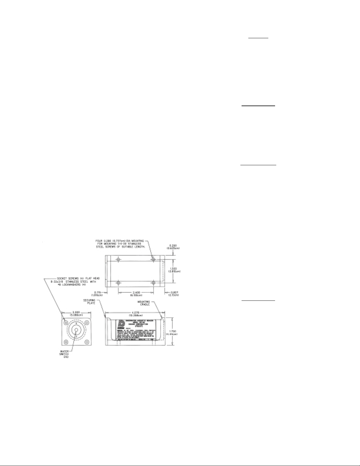
2.6.1. GENERAL. Model N30A26 Series
Mounting Kit (Cradle Type) is an aluminum
extrusion with a screw-attached securing plate
that provides rugged mounting and protection of
the beacon within the aircraft. See Figure 3. The
beacon should be mounted horizontally with the
switch end forward, if possible. If vertical
mounting is necessary, switch end must be
mounted downward to prevent accumulation of
dirt, grease and water on the switch end.
NOTE
The mounting bracket can be used as a template to mark for drilling the holes prior to
the installation of beacon. Always remove
beacon from mount prior to marking or drilling.
CAUTION
WHEN MOUNTING TO THE AIRFRAME, CHECK THE OPPOSITE
SIDE OF THE FRAME OR BULKHEAD
FOR DRILLING CLEARANCE.
2.6.2. CRADLE MOUNTING PROCEDURE.
A. Using Figure 3 as a guide, locate the four
0.290 inch (0.737 cm) diameter holes on 1.500
by 2.400 inch (3.810 by 6.100 cm) centers. Be
sure access to the securing plate end is available
for future beacon installation and removal.
Approximately 4.5 inches (11.43 cm) clearance
should be allowed for beacon removal.
WARNING
USE PROTECTIVE EYE EQUIPMENT
DURING DRILLING OPERATION.
B. After the four 0.290 inch (0.737 cm) diameter
holes have been located, drill the holes with an
“L” twist drill.
C. Secure the mounting cradle to the aircraft
structure with four 1/4-20 stainless steel screws
and associated washers and nuts (not furnished),
as shown in Figure 3. Alternate mounting with
threaded holes may be employed where structure
does not permit nuts on rear side.
CAUTION
DO NOT ADD ANY UNAPPROVED
STAMP, ETCHING, OR LABEL TO
THE BEACON CASE OR END CAPS.
Figure 3. N30A26 Series Mounting
Kit Installation Details
03-TM-0037 REV 13
2.6.3. INSTALLING DK100/DK120 BEACON
INTO N30A26 SERIES MOUNTING KIT.
A. If the securing plate and its attaching hardware are already attached to the main body of the
mounting cradle, remove them.
B. Make sure that the beacon case and water
switch are free of grease or film. If in doubt,
wipe clean with mild detergent.
Page 9 of 24
Page 10
C. Test the beacon as outlined in Section IV to
insure operation prior to installation.
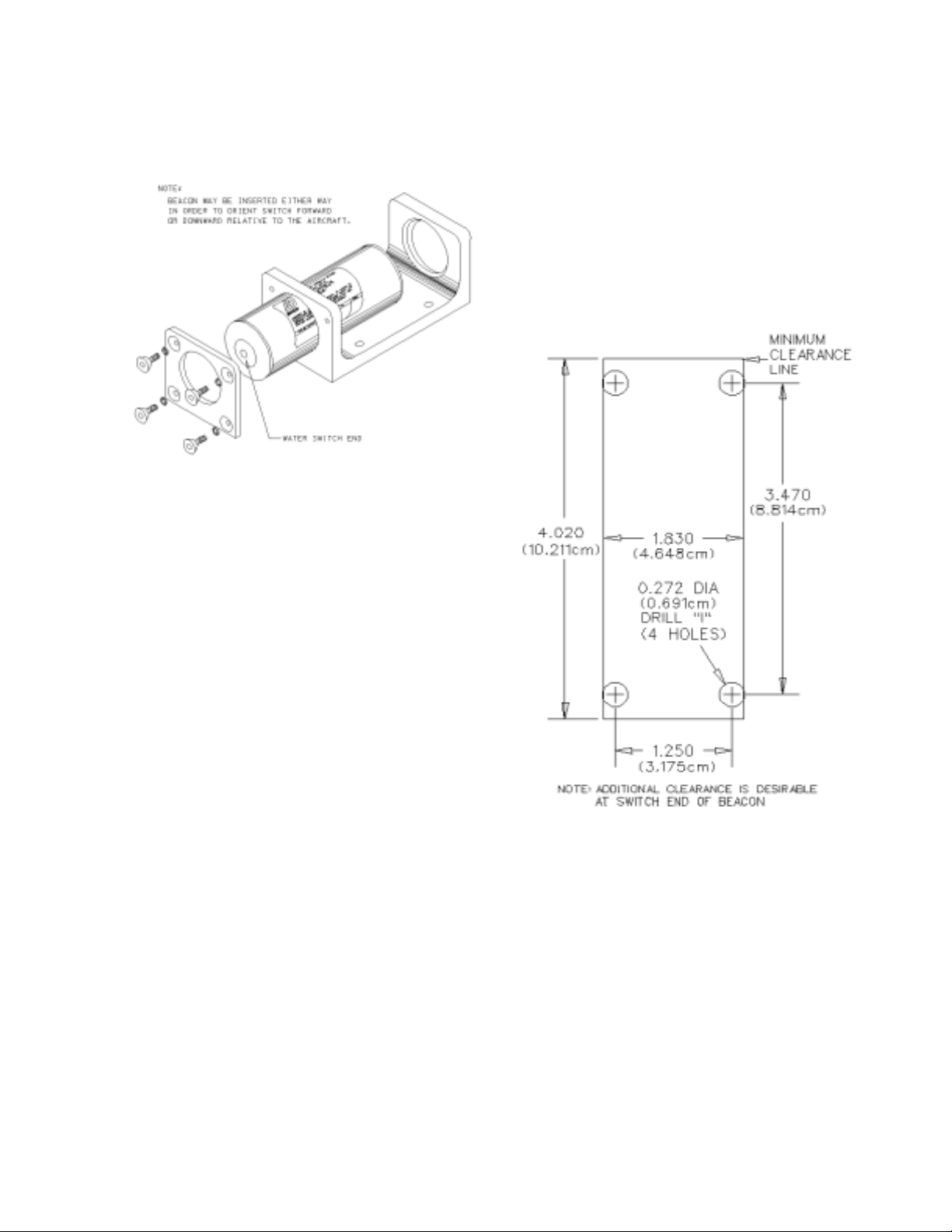
Figure 4. Installation of N30A26
Series Mounting Kit and Beacon
2.7.2. MOUNTING PROCEDURE
A. Lay out four holes as shown in Figure 5.
Position mounting kit carefully to avoid interference with other structures. Observe the clearances required as shown in Figures 5 and 6, and
in established tool and maintenance clearances.
B. Drill the four 0.272 inch (0.691 cm) (“I” drill)
holes in the mounting surface as shown in Figure
5.
D. Insert the beacon into the mounting cradle
with the water switch facing forward and/or
downward with reference to the aircraft. Rotate
the beacon in the mount so that the beacon
replacement date can be read. See Figure 4.
E. Screw securing plate in place with the set of
furnished screws and washers. Tighten until the
securing plate makes contact with the frame in
the area of the screws, with approximately 15 to
20 inch-pounds torque.
F. Perform the Operational Test outlined in
Section IV.
2.7. INSTALLATION PROCEDURES FOR
THE DK100/DK120 AND THE N30A21A
MOUNTING KIT.
2.7.1. GENERAL. Space limitations sometimes
require the use of the strap-type N30A21A
Mounting Kit. Where a choice exists, horizontal
mounting with switch forward is best. If vertical
mounting is employed, mount switch down to
reduce accumulation of grease, dirt, and water on
the switch end of the beacon.
Figure 5. Mounting Hole Template
for N30A21A Mounting Kit
C. Test the beacon as outlined in Section IV to
insure operation prior to installation.
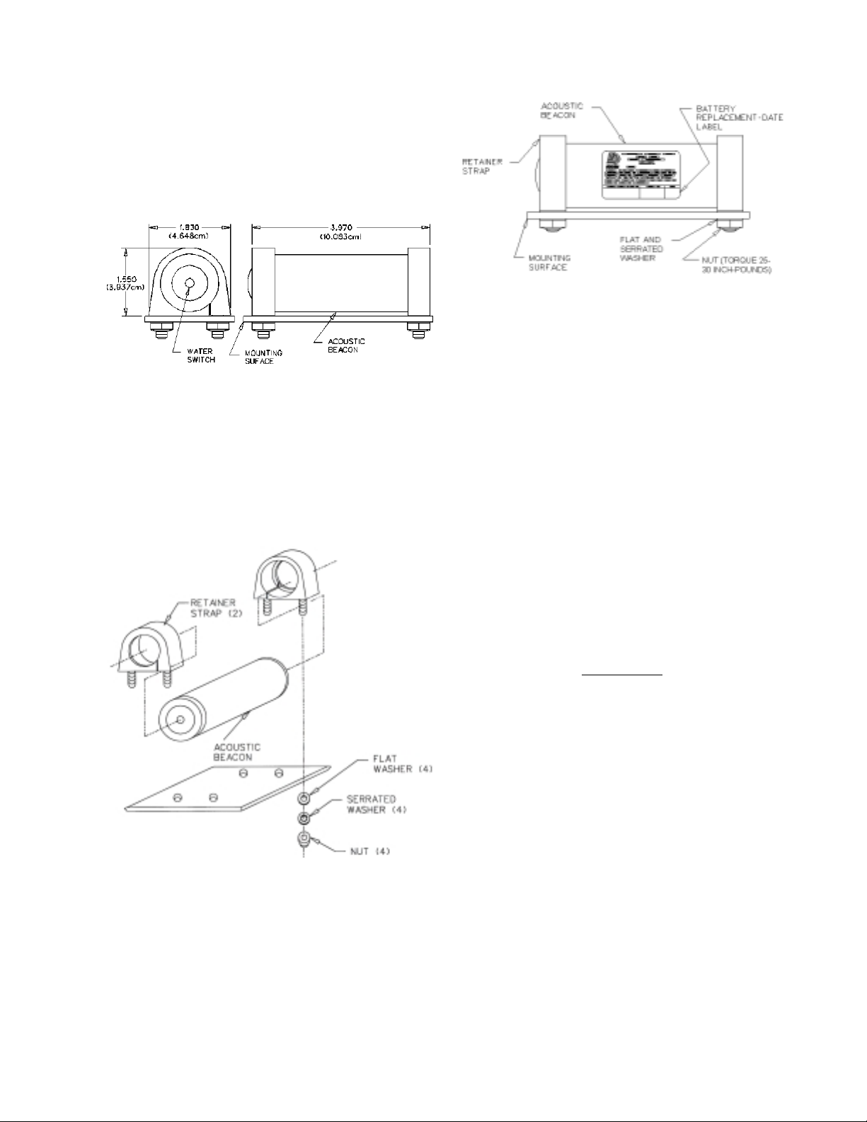
D. Slip the retainer straps of the mounting kit
over the ends of the beacon. See Figures 7 and 8.
E. Insert the ends of the retainer straps through
the 0.272 inch (0.691 cm) holes in the mounting
surface. When horizontal mounting is used,
position beacon with switch end forward.
03-TM-0037 REV 13
Page 10 of 24
Page 11
If vertical mounting is employed, the switch end
should be facing downwards to reduce the
accumulation of dirt, grease, and water on the
switch end. Rotate the beacon in the mount, so
that the markings and beacon replacement date
label can be read.
Figure 6. N30A21A Mounting Kit
and Beacon Overall Dimensions
F. Install a flat washer and nut on each end of the
retainer straps.
Figure 8. Securing Beacon in
N30A21A Mounting Kit
2.7.3. INSTALLING BEACON INTO
N30A21A MOUNTING KIT.
A. Test the beacon as outlined in Section IV to
insure operation prior to installation.
B. Torque the four nuts to 25 to 30 inch-pounds.
Be sure that all four studs protrude approximately the same amount to insure that the strap
seats properly around the beacon.
Figure 7. Method of Installing the
N30A21A Mounting Kit
C. Make sure that the beacon case and water
switch are free of grease film. If in doubt, wipe
clean with mild detergent.
CAUTION
ADDITIONAL UNAPPROVED STAMP OR
LABEL ON BEACON CASE WILL REDUCE ACOUSTIC RADIATION.
D. Perform the Operational Test outlined in
Section IV.
03-TM-0037 REV 13
Page 11 of 24
Page 12
2.8. INSTALLATION PROCEDURES FOR
THE DK130/DK140 AND THE N30A29
SERIES MOUNTING KIT.
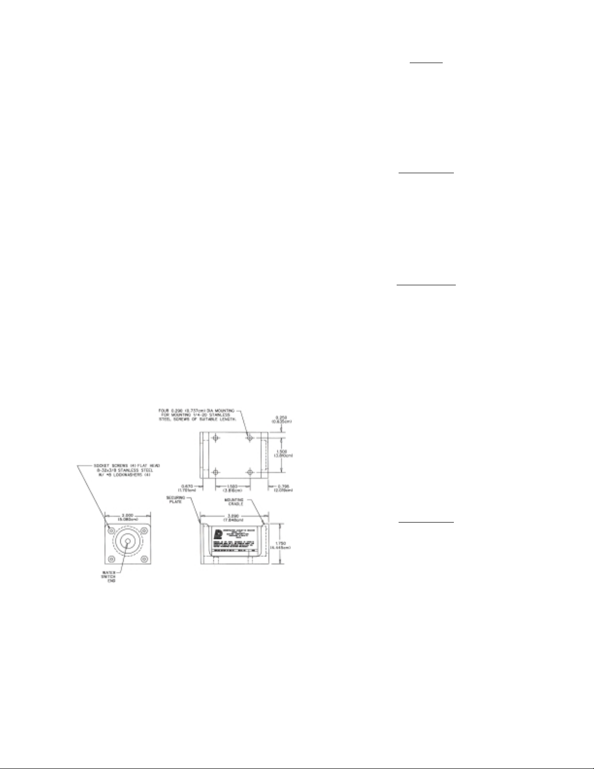
2.8.1. GENERAL. Model N30A29 Series
Mounting Kit (Cradle Type) is an aluminum
extrusion with a screw-attached securing plate
that provides rugged mounting and protection of
the beacon within the aircraft. See Figure 9. The
beacon should be mounted horizontally with the
switch end forward, if possible. If vertical
mounting is necessary, switch end must be
mounted downward to prevent accumulation of
dirt, grease and water on the switch end.
NOTE
The mounting bracket can be used as a
template to mark for drilling the holes
prior to the installation of the beacon.
Always remove the beacon from the mount
prior to marking or drilling.
CAUTION
WHEN MOUNTING TO THE AIRFRAME, CHECK THE OPPOSITE
SIDE OF THE FRAME OR BULKHEAD FOR DRILLING CLEARANCE.
2.8.2. CRADLE MOUNTING PROCEDURE.
A. Using Figure 9 as a guide, locate the four
0.290 inch (0.737 cm) diameter holes on 1.500 in
by 1.500 in (3.810 by 3.810 cm) centers. Be sure
access to the securing plate end is available for
future beacon installation and removal. Approximately 4.5 inches (11.43 cm) clearance should
be allowed for beacon removal.
WARNING
USE PROTECTIVE EYE EQUIPMENT DURING DRILLING OPERATION.
B. After the four 0.290-inch (0.737 cm) diameter
holes have been located, drill the holes with an
“L” twist drill.
C. Secure the mounting cradle to the aircraft
structure with four 1/4-20 stainless steel screws
and associated washers and nuts (not furnished),
as shown in Figure 9. Alternate mounting with
threaded holes may be employed where structure
does not permit nuts on rear side.
CAUTION
DO NOT ADD ANY UNAPPROVED
STAMP, ETCHING, OR LABEL TO
THE BEACON CASE OR END CAPS.
Figure 9. N30A29 Mounting Kit
Installation Details
03-TM-0037 REV 13
2.8.3. INSTALLING DK130/DK140 BEACON
INTO N30A29 SERIES MOUNTING KIT.
A. If the securing plate and its attaching hardware are already attached to the main body of the
mounting cradle, remove them.
Page 12 of 24
Page 13
B. Make sure that the beacon case and water
switch, are free of grease or film. If in doubt,
wipe clean with mild detergent
C. Test the beacon as outlined in Section IV to
insure operation prior to installation.
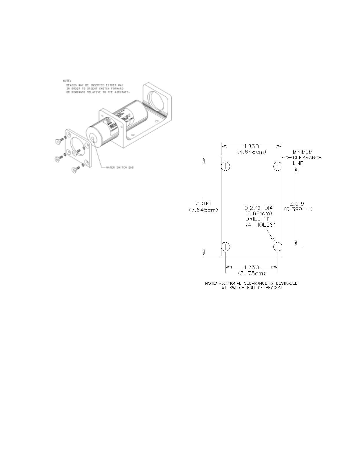
Figure 10. Installation of N30A29
Series Mounting Kit and Beacon
2.9.2. MOUNTING PROCEDURE.
A. Lay out four holes as shown in Figure 11. Position mounting kit carefully to avoid
interferencewith other structures. Observe the
clearances required as shown in Figures 11 and
12, and in established tool and maintenance clearances.
B. Drill the four 0.272 inch (0.691 cm) (“I” drill)
holes in the mounting surface as shown in Figure
11.
D. Insert the beacon into the mounting cradle
with the water switch facing forward and/or
downward with reference to the aircraft. Rotate
the beacon in the mount so that the beacon
replacement date can be read. See Figure 10.
E. Screw securing plate in place with the set of
furnished screws and washers. Tighten until the
securing plate makes contact with the frame in
the area of the screws, with approximately 15 to
20 inch-pounds torque.
F. Perform the Operational Test outlined in
Section IV.
2.9. INSTALLATION PROCEDURES FOR
THE DK130/DK140 AND THE N30A21A
MOUNTING KIT.
2.9.1. GENERAL. Space limitations sometimes
require the use of the strap-type N30A21A Mounting Kit. Where a choice exists, horizontal mounting with switch forward is best. If vertical mounting is employed, mount switch down to reduce
accumulation of grease, dirt, and water on the
switch end of the beacon.
Figure 11. Mounting Hole Template
for N30A21A Mounting Kit
C. Test the beacon as outlined in Section IV to
insure operation prior to installation.
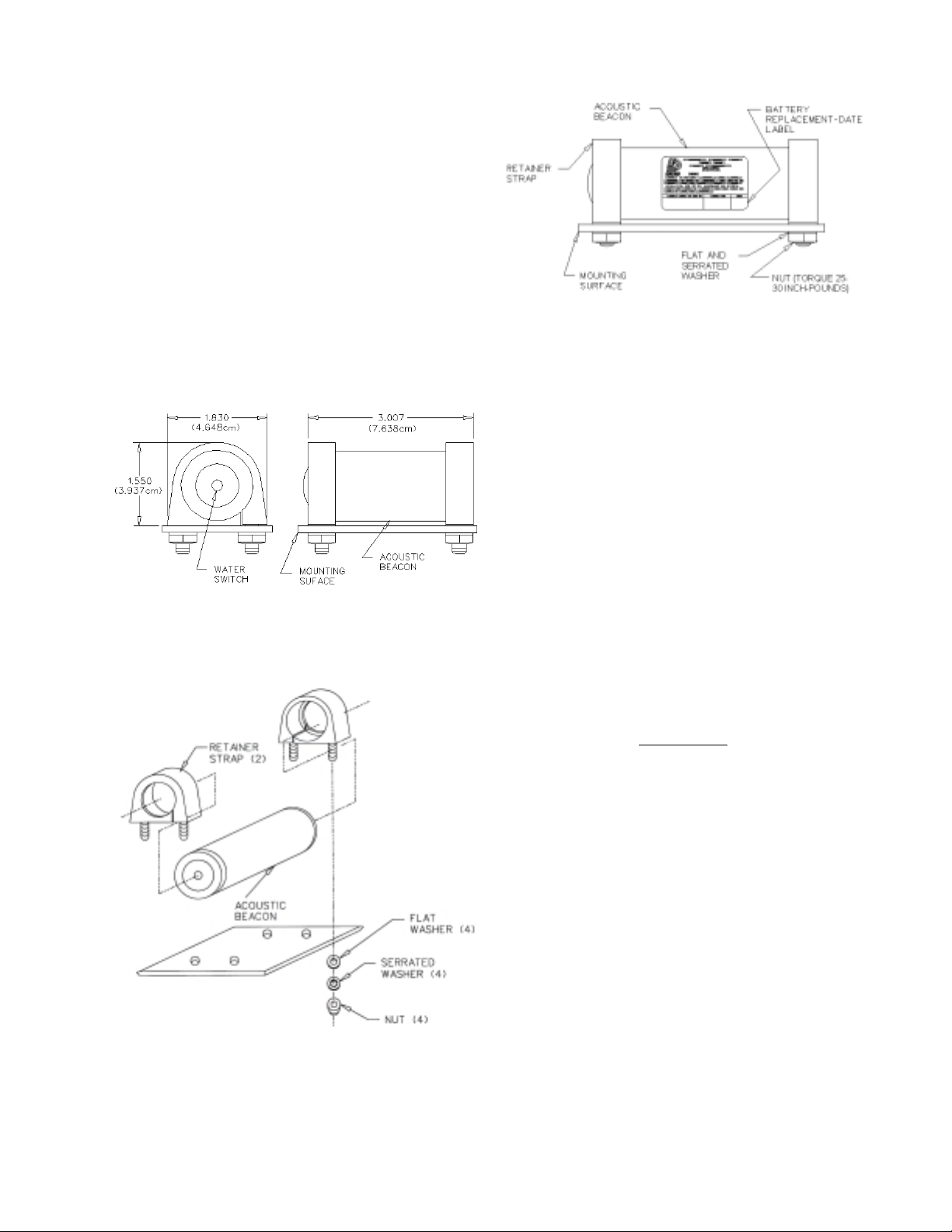
D. Slip the retainer straps of the mounting kit
over the ends of the beacon. See Figures 13 and
14.
03-TM-0037 REV 13
Page 13 of 24
Page 14
E. Insert the ends of the retainer straps through
the 0.272 inch (0.691 cm) holes in the mounting
surface. When horizontal mounting is used,
position beacon with switch end forward. If
vertical mounting is employed, the switch end
should be facing downwards to reduce the
accumulation of grease and dirt on the switch
end. Rotate the beacon in the mount, so that the
markings and beacon replacement date label can
be read.
F. Install a flat washer and nut on each end of the
retainer straps.
Figure 12. N30A21A Mounting Kit
and Beacon Overall Dimensions
Figure 14. Securing Beacon In
N30A21A Mounting Kit
2.9.3. INSTALLING BEACON INTO N30A21A
MOUNTING KIT.
A. Test the beacon as outlined in Section IV to
insure operation prior to installation.
B. Torque the four nuts to 25 to 30 inch-pounds.
Be sure that all four studs protrude approximately the same amount to insure that the strap
seats properly around the beacon.
C. Make sure that the beacon case and water
switch are free of grease film. If in doubt, wipe
clean with mild detergent.
CAUTION
ADDITIONAL UNAPPROVED
STAMPS OR LABELS ON THE BEACON CASE WILL REDUCE ACOUSTIC RADIATION.
Figure 13. Method of Installing the
N30A21A Mounting Kit
03-TM-0037 REV 13
D. Perform the Operational Test outlined in
Section IV.
Page 14 of 24
Page 15

SECTION III
OPERATION
3.1. THEORY OF OPERATION.
3.1.1. The DK Series beacon is a battery-oper-
ated underwater acoustic pulse generator that is
activated when the water switch is immersed in
either fresh or salt water.
Figure 15. Nominal Pulse Train
3.1.2. The water switch is part of a triggering
circuit, which when actuated will initiate normal
pulsing of the beacon circuit. The signal is
coupled to a piezo-ceramic transducer ring. This
results in mechanical motion that is transmitted
to the metal case of the beacon, which in turn,
radiates acoustic energy into the surrounding
water at 37.5 kHz.
3.1.3. The pulses generated are approximately 10
milliseconds in duration, and occur about once
per second in water. See Figure 15. The beacon
will operate for a minimum of 30 days after
being immersed in the water. The beacon will
withstand depths to 20,000 feet (6096 meters). It
can be detected at a range of 2000 to 4000 yards
(1800 to 3600 meters). The sea state, nearby
boats, marine animals, gas or oil lines, and other
factors contributing to the ambient noise level
will affect the range at which the beacon can be
detected.
03-TM-0037 REV 13
Page 15 of 24
Page 16
SECTION IV
TESTING
4.1. GENERAL.
The DK Series beacon should be tested before
and after installation in the mounting kit and at
recommended maintenance intervals. See Sections V and VI.
4.2. BATTERY TESTING.
CODE MINIMUM ACCEPTABLE
VOLTAGE
A 3.55 VOLTS
B 2.97 VOLTS
Use a high impedance voltmeter (input impedance of 10 M ohms) (not required when using
TS100 or TS200 Test Set) to perform the following procedure:
A. Make sure the case and water switch are clean
and dry prior to testing. If in doubt, wipe clean
using mild detergent and a soft cloth.
B. Place the negative lead of the high impedance
voltmeter on the water switch pin and the positive lead of the meter on the beacon case or the
mounting kit, if already installed.
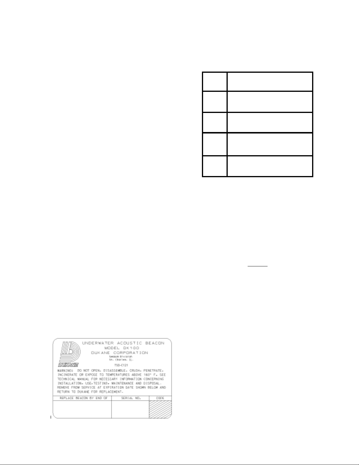
C. Measure the battery voltage. Note: Inspect
label on beacon to determine battery code. See
Figure 16 (shaded area) and refer to Figure 17
for voltage specifications. The beacon is operable at the given minimum acceptable voltage.
For DK Series beacons if the battery voltage is
below the minimum acceptable voltage remove
the beacon from service and contact Dukane
Corporation for instructions.
C 2.97 VOLTS
D 2.97 VOLTS
Figure 17. Beacon Voltage Code
4.3. OPERATIONAL TESTING.
The 42A12 Series Ultrasonic Test Set, PL-1,
PL-3 Operational Tester, TS100, or TS200
Portable Test Set can be used to perform operational tests on the beacon.
NOTE
The procedure for use of the 42A12 Series
Ultrasonic Test Set is contained in the
42A12 Series manual.
The procedure for use of the PL-1 and PL-3 is
available upon request.
The procedure for use of the TS100 or the TS200
Portable Test Set is contained in the Test Set
manual.
Figure 16. Typical Beacon Label
03-TM-0037 REV 13
The TS100 Portable Test Set is not compatible
with the model DK130 or the DK140 Underwater Acoustic Beacons. The TS200 Test Set is
compatible with the DK100, DK120, DK130 and
the DK140 Underwater Acoustic Beacons.
Page 16 of 24
Page 17

SECTION V
MAINTENANCE DK100/DK130
5.1. GENERAL.
This section contains DK100/DK130 Beacon
cleaning, beacon testing, battery testing, disposal
and storage procedures. Initially beacons must be
tested at every installation or beacon change. The
required schedule for battery replacement,
available only at Dukane Corporation is every
six years.
When the beacon is installed on the aircraft, the
recommended schedule for beacon cleaning and
testing is every 24 months, when the beacon is
installed on a recorder and the recorder is installed in accordance with its TSO. For nonrecorder aircraft installations the recommended
schedule is every six months.
5.2. BEACON CLEANING.
Clean the switch end of the beacon with a soft
cloth and mild detergent, then dry thoroughly
with a clean cloth. Clean the switch end insulator
to prevent leakage currents from occurring
across the switch. This will affect battery life.
The water switch should be cleaned when dirt or
dust becomes apparent.
5.4.3. Any situation that could possibly crush or
penetrate the case of the beacon should be
avoided.
5.5. BATTERY.
WARNING
REMOVAL OF BATTERY FROM BEACON WILL VOID THE WARRANTY.
The beacon requires NO battery maintenance.
DO NOT remove the battery at any time. The
beacon must be taken out of service according to
the expiration date printed on the beacon case
and returned to the factory for service. See
Section IX for beacon Return Procedures.
WARNING
FAILURE TO OBSERVE THE ABOVE
PRECAUTIONS COULD RESULT IN
THE RELEASE OF HAZARDOUS
CHEMICALS.
5.6. BEACON DISPOSAL.
5.3. BEACON TESTING.
5.3.1. Make sure that the beacon case is clean
and dry prior to testing.
5.3.2. See Sections 4.2. and 4.3. for testing
procedures.
5.4. PRECAUTIONS.
5.4.1. The DK100/DK130 Beacons must not be
exposed to heat in excess of 160°F (71°C).
5.4.2. The beacon must not be disassembled in
any way. Any disassembly of the beacon will
void the warranty.
03-TM-0037 REV 13
Should it be necessary to dispose of the beacon
for any reason, DO NOT THROW IT AWAY.
This beacon contains a lithium battery and may
be considered hazardous waste. Regulations are
not consistent from one territory to another,
please contact your State Authority for current
information.
5.7. BEACON STORAGE.
When long term storage of the beacon is required, the beacon should be stored in the original shipping container (or equivalent). Make sure
it is stored in a cool dry environment.
Page 17 of 24
Page 18

SECTION VI
MAINTENANCE DK120/DK140
6.1. GENERAL.
This section contains DK120/DK140 Beacon
cleaning, beacon testing, battery replacement and
testing, disposal and storage procedures. Initially
beacons must be tested at every installation or
battery change. The required schedule for Battery Replacement and Off-Current Testing is
every six years.
When the beacon is installed on the aircraft, the
recommended schedule for beacon cleaning and
testing is every 24 months, when the beacon is
installed on a recorder and the recorder is installed in accordance with its TSO. For nonrecorder aircraft installations the recommended
schedule is every six months.
6.2. BEACON CLEANING.
Clean the switch end of the beacon with a soft
cloth and mild detergent, then dry thoroughly
with a clean cloth. Clean the switch end insulator
to prevent leakage currents from occurring
across the switch. This will affect battery life.
The water switch should be cleaned when dirt or
dust becomes apparent.
6.4.2. Any situation that could possibly crush or
penetrate the case of the beacon should be
avoided.
6.5. BEACON DISASSEMBLY.
Disassembly of the beacon is limited to battery
replacement, as outlined in Section 6.6.
6.6. BATTERY REPLACEMENT AND TESTING.
WARNING
INCORRECT INSTALLATION OF
BATTERY WILL CAUSE PERMANENT DAMAGE TO BEACON.
6.6.1. GENERAL. Battery replacement should
be done in a maintenance shop under clean
conditions to prevent dust from contaminating
O-ring and lubricant. Because the old O-ring
may have developed a set with age, O-ring
replacement is mandatory at the time of battery
change. O-ring lubrication should be applied to
new O-ring and threads before installation.
6.3. BEACON TESTING.
6.3.1. Make sure that the beacon case is clean
and dry prior to testing.
6.3.2. See Sections 4.2. and 4.3. for testing
procedures.
6.4. PRECAUTIONS.
6.4.1. The DK120/DK140 Beacon must not be
exposed to temperatures in excess of 160°F
(71°C).
03-TM-0037 REV 13
NOTE
Replacement of the battery in the DK120
or DK140 beacon must be done by a
qualified technician.
CAUTION
TO AVOID INTERNAL DAMAGE, DO
NOT CLAMP THE BEACON IN A
VISE, UNLESS A VISE-CLAMP (P/N
810-546) IS USED.
Page 18 of 24
Page 19
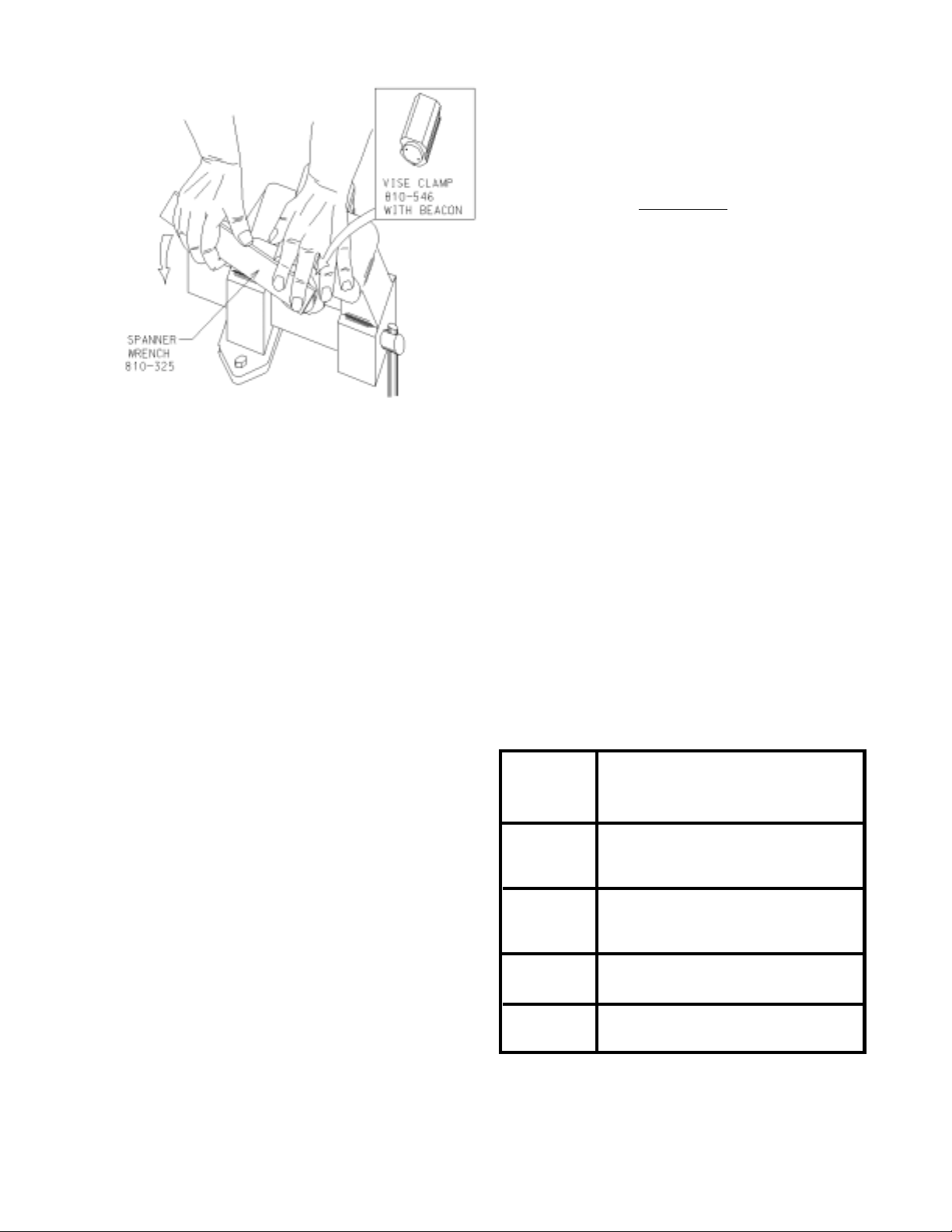
Figure 18. Battery End Cover Re-
moval With Vise Clamp and Span-
ner Wrench
6.6.2. BATTERY REPLACEMENT.
A. Both the Vise Clamp (P/N 810-546) and the
Spanner Wrench (P/N 810-325) are available in
kit P/N 810-2007/KVS.
G. Clean the threads, O-ring groove in the body
and the threads on the cover by wiping them
thoroughly with solvent.
CAUTION
FOREIGN SUBSTANCES IN LUBRICANT ON SEALING SURFACES MAY
DAMAGE THREADS AND/OR ALLOW WATER LEAKAGE THROUGH
THE O-RING SEAL. SCRATCHES OR
GOUGES ON SEALING SURFACES
WILL ALSO CAUSE WATER LEAKAGE.
H. Carefully install a new O-ring on the battery
cover. Apply a thin coating of O-ring lubricant
(P/N 810-346, 810-500 or 810-1168) to O-ring,
O-ring groove and threads. NOTE: O-ring,
lubricant and battery are provided in battery
replacement kit see Figure 19 for battery kit
number. Contact Dukane Corporation, Seacom
Division at (630) 762-4050, for replacement
battery kits.
B. Secure the beacon with Vise-Clamp (P/N
810-546) as shown in Figure 18.
C. Use Spanner Wrench (P/N 810-325) to remove the battery end cover with 2 wrench holes
by unscrewing counterclockwise. The breakaway
torque is usually high so spanner wrench should
be held firmly in contact with battery end cover
in order to prevent damage to wrench holes.
D. Remove shock cushion from battery end of
beacon if not removed with cover.
E. Remove the old O-ring from the cover. Do not
use a steel screwdriver or sharp tool because of
danger of damaging O-ring groove.
F. Remove the old battery. NOTE: Insure that
the battery pad remains in beacon.
I. Install new battery. Be sure the end marked
“INSERT THIS END FIRST “ goes in first. See
Figure 20.
CODE
A
B
C
D
REQUIRED BATTERY KIT
NOT AVAILABLE
810-2007/K
810-2008/K
810-2015/K
FIGURE 19. Battery Kit
03-TM-0037 REV 13
Page 19 of 24
Page 20
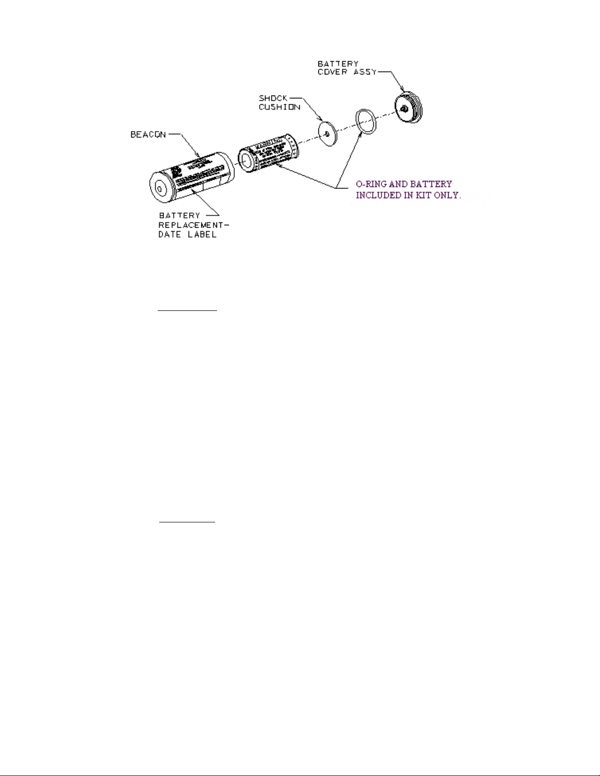
Figure 20. Beacon Exploded View Showing Relative Location of Battery
and Related Parts
WARNING
REPLACE BATTERY WITH AUTHORIZED REPLACEMENT PARTS
ONLY. USE OF AN UNAUTHORIZED BATTERY WILL VOID THE
WARRANTY AND MAY CAUSE AN
INOPERATIVE OR DANGEROUS
CONDITION. USE OF AN UNAUTHORIZED BATTERY MAY
PRESENT A RISK OF FIRE OR
EXPLOSION. SEE FIGURE 19 PAGE
18 FOR REPLACEMENT BATTERY
KIT.
CAUTION
DO NOT RECHARGE, DISASSEMBLE, HEAT ABOVE 160°F (71°C)
OR INCINERATE. DISPOSE OF THE
BATTERIES PROMPTLY (IN ACCORDANCE WITH ALL LOCAL
STATE AND FEDERAL REQUIREMENTS), KEEP AWAY FROM CHILDREN. THERE IS A RISK OF BATTERY FIRE, EXPLOSION, AND
BURNS.
J. Perform OFF-CURRENT TEST as outlined in
Section 6.7.
K. Position rubber shock cushion around contact
spring and on the inside of the battery cover.
L. Replace the cover and tighten it until the
cover flange contacts the body or leaves less than
a 0.003 inch gap. Use hand force only on the
wrench. Hold the beacon in a vise clamp as
shown in Figure 18. Clean the beacon exterior of
excess O-ring grease.
M. Perform operational test of beacon as outlined in Section IV.
N. Replace the battery replacement date label on
the outside of the beacon case with the new label
supplied with the battery. Locate the label on the
beacon body in the space provided as shown in
Figure 21. Never put label on the water switch
end of the beacon. Place the new label on the
beacon after the beacon is installed in the mount.
03-TM-0037 REV 13
Page 20 of 24
Page 21
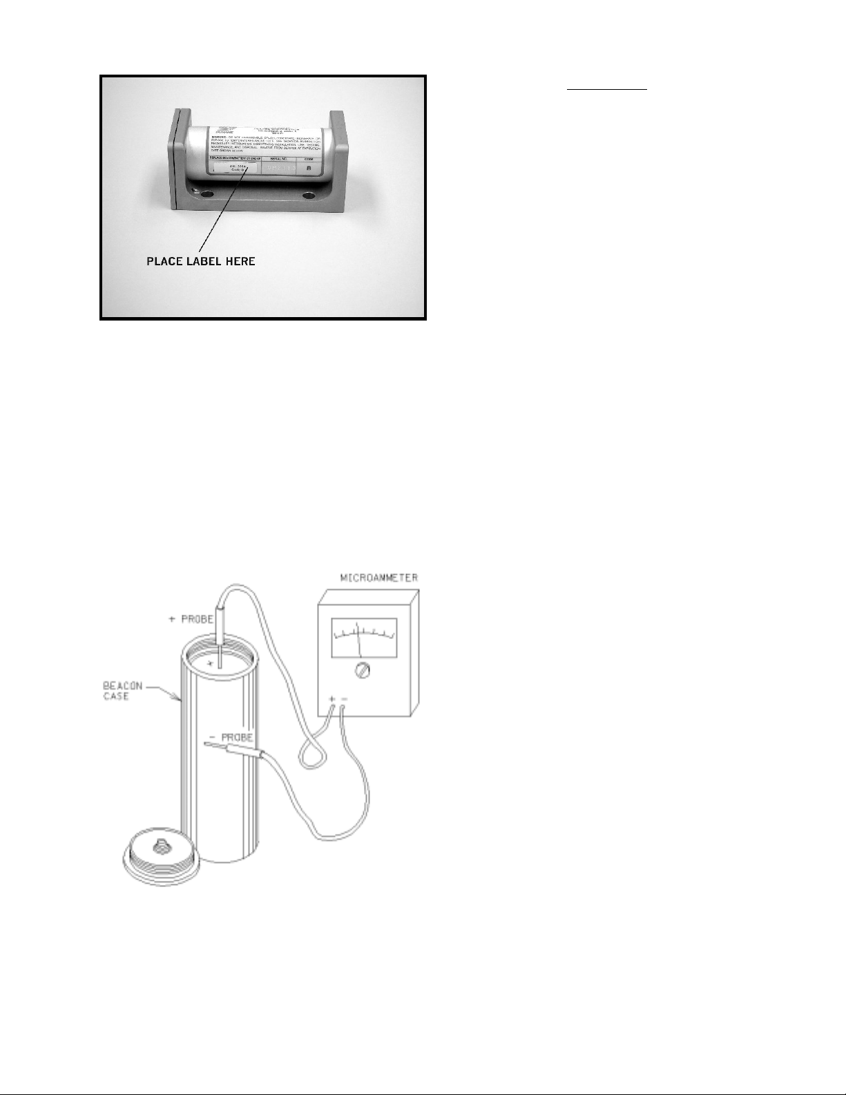
Figure 21. RBB Label Placement
WARNING
DO NOT RECHARGE, DISASSEMBLE, HEAT ABOVE 160°F (71°C)
OR INCINERATE. THERE IS A RISK
OF BATTERY FIRE, EXPLOSION,
AND BURNS.
6.8. BATTERY DISPOSAL.
Dispose of battery in accordance with all local,
state and federal regulations. Dispose of batteries
promptly, keep away from children.
6.7. BEACON OFF-CURRENT TEST.
Connect test leads as shown in Figure 22 and
check for current leakage between battery and
beacon body. The battery OFF current must be
less than 3 microamperes. Beacons with greater
than 3 microamperes OFF current should be
taken out of service immediately.
6.9. BEACON STORAGE.
When long term storage of a beacon is required,
the beacon should be stored in the original
shipping container (or equivalent). Make sure it
is stored in a cool dry environment. The beacon
should be stored without battery.
6.10. BEACON OVERHAUL.
The acoustic characteristics of the beacon shall
be checked after 18 years of service to insure
that the beacon it is still in compliance with FAA
regulations.
Figure 22. Beacon Off-Current Test
Set-Up
03-TM-0037 REV 13
Page 21 of 24
Page 22

SECTION VII
WARRANTY DK100/DK120/DK130/DK140
The Dukane Corporation warrants that the electronics and case of the Model DK100/DK120DK130/
DK140 Underwater Acoustic Beacon (hereafter referred to as the “unit”) will be free from defects in
materials and workmanship for six years from the date of shipment from Dukane Corporation.
Dukane Corporation will remanufacture or replace any unit or battery found not to be in conformity
with this warranty.
In accordance with the Technical Manual published by Dukane Corporation the customer is responsible for the following items: (1) periodic testing of the units in service; (2) removing and shipping,
prepaid, any inoperative units back to Dukane Corporation; (3) installing any replacement units.
This warranty does not cover: (i) defects caused by the customer’s failure to use, test or maintain any
unit in accordance with Dukane Corporation’s Technical Manual; (ii) product failures caused by
abuse, misuse or neglect; or (iii) any product where the customer has attempted any repair or service
of the internal components.
Dukane Corporation’s liability under this warranty is limited to repair or replacement of a unit or
battery that is defective.
DUKANE CORPORATION SHALL NOT BE LIABLE FOR ANY INCIDENTAL, SPECIAL
CONSEQUENTIAL OR EXEMPLARY DAMAGES ARISING OUT OF THE INSTALLATION,
USE, TESTING, SERVICING OR MAINTENANCE OF ANY UNIT.
THIS WARRANTY IS GIVEN IN LIEU OF ALL OTHER WARRANTIES, EXPRESS OR IMPLIED, INCLUDING THE WARRANTIES OF MERCHANTABILITY OR FITNESS FOR A
PARTICULAR PURPOSE.
03-TM-0037 REV 13
Page 22 of 24
Page 23

SECTION VIII
SERVICE PROGRAM DK100/DK120/DK130/DK140
8.1. BEACON RETURN – DEFECTIVE.
8.1.1. In the case of a failure which is determined
to be within the Warranty terms (Section VII),
the beacon will be replaced by Dukane Corporation at the sole discretion of Dukane Corporation.
8.1.2. When a beacon is returned to the customer
after warranty service, the remainder of the
original warranty will be applied to the returned
beacon.
8.2. BEACON RETURN - NO DEFECT.
If the beacon is returned to Dukane Corporation
and is found to be operational, the beacon will be
returned to the customer shipping collect. In
addition, the customer will be notified that an
analysis fee applies.
8.3. BEACON RETURN - OUT OF WAR-
RANTY.
If the beacon is returned to Dukane Corporation
and is found to be out of Warranty, the cost
of an overhauled beacon will be determined and
the customer will be notified for the appropriate
approvals.
8.4. BATTERY CHANGE/OVERHAUL FOR THE DK100 & DK130.
8.4.1. At or near the expiration date listed on the
case, the beacon can be returned to Dukane
Corporation for battery change and overhaul to
appropriate standards. (See Section 9.2.)
8.4.2. The Overhaul Program consists of: 1) a
comprehensive series of operational tests to
verify the performance of the beacon to its
published specifications; 2) a replacement
battery; and 3) an additional warranty for another
six years. Each shipment of overhauled beacons
will include the necessary documentation to
indicate that the product being returned meets its
published specifications and that the product
could be new or overhauled, at the discretion of
Dukane Corporation. Dukane Corporation’s
standard procedure is to not return the original
serial number when a beacon is overhauled. A
different unit with a different serial number will
be supplied from Dukane Corporation’s common
stock.
Notes:
1. See Section IX for information about how to return the beacon to Dukane Corporation for service.
2. Call Dukane Corporation, Seacom Division at (630) 762-4056 for appropriate service charges or
further information about the Service Program.
03-TM-0037 REV 13
Page 23 of 24
Page 24

SECTION IX
PROCEDURE FOR RETURNING DK SERIES BEACON TO FACTORY
9.1. BEACON SERVICE.
9.1.1. PACKAGING. Insure that proper protec-
tion for the beacon is provided i.e. protection
from inadvertent shorting of the water switch
and protection from surface scratches or abrasions.
9.1.2. INFORMATION TO BE INCLUDED
WITH THE BEACON.
A. Reason for the return.
B. Serial Number of the beacon(s).
C. Return Authorization Number (See 9.1.3.).
D. Purchase Order (if required) for Beacon
Replacement.
9.1.3. RETURN AUTHORIZATION. Prior to
shipping the beacon to Dukane Corporation, a
Return Authorization Number may be required
and can be obtained from Dukane Corporation,
Seacom Division’s Service Department by
calling (630)762-4056, or via Fax (630)7624049, or via e-mail at [email protected].
NOTE
This product is powered by a lithium battery and
may require special shipping, labeling, packing
and packaging.
If your beacon has a Battery Code of A or B (see
label on beacon for Battery Code), you may be
required to ship this product as Class 9 Hazardous Material. Contact your State Authority for
shipping regulations.
9.1.4. SHIPPING INSTRUCTIONS. When the
beacon is returned under warranty, ship to:
Dukane Corporation
Seacom Division
2900 Dukane Drive
St. Charles, IL 60174
Attn: Seacom Service Department
Code 4056
Return Authorization Number
9.2. BATTERY CHANGE/OVERHAUL.
9.2.1. PACKAGING. Insure that proper protection for the beacon is provided i.e. protection
from inadvertent shorting of the water switch
and protection from surface scratches or abrasions.
9.2.2. PROCEDURE-CUSTOMER.
A. Contact Dukane Corporation, Seacom
Division’s Service Department, (630) 762-4056,
or via Fax (630)762-4049, or via e-mail at
[email protected]. Provide the following
information:
1. Quantity of beacons that are being returned.
2. Purchase Order, for beacon replacement.
3. Shipping and billing addresses.
4. Shipping carrier.
5. Collect account number for shipping carrier, if
applicable.
6. Contact name and phone number.
B. Ship beacons to Dukane Corporation per
9.1.4. along with a copy of the Purchase Order.
9.2.3. PROCEDURE-DUKANE. Upon receipt
of the beacons and a Purchase Order, the appropriate quantity of overhauled beacons will be
shipped FOB St. Charles, IL.
03-TM-0037 REV 13
Page 24 of 24
Page 25

03-TM-0037 REV 13
Page 25 of 24
 Loading...