

R
ENGLISH
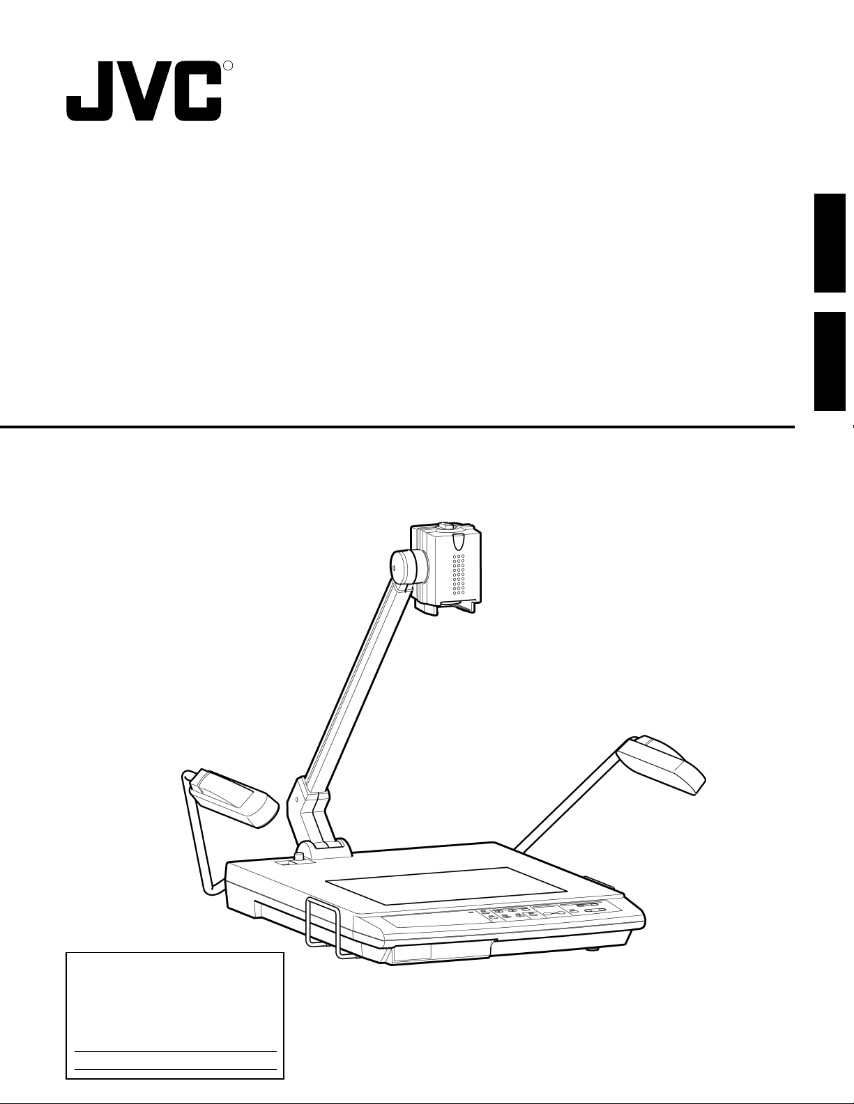
DIGITAL PRESENTER
MANUEL D’INSTRUCTIONS : PRESENTOIR NUMÉRIQUE
OPERATING INSTRUCTIONS
AV-P1000U
FRANÇAIS
For Customer Use:
Enter below the Serial No. which
are located on the fram.
Retain this information for future
reference.
Model No. AV-P1000U
Serial No.
This instruction book is made from 100% recycled paper.
SS961490-002
CAUTION
RISK OF ELECTRIC SHOCK
DO NOT OPEN
CAUTION: TO REDUCE THE RISK OF ELECTRIC SHOCK.
DO NOT REMOVE COVER (OR BACK).
NO USER SERVICEABLE PARTS INSIDE.
REFER SERVICING TO QUALIFIED SERVICE PERSONNEL.
The lightning flash with arrowhead symbol,
within an equilateral triangle is intended to alert
the user to the presence of uninsulated “dangerous voltage” within the product’s enclosure
that maybe of sufficient magnitude to constitute a risk of electric shock to persons.
The exclamation point within an equilateral
triangle is intended to alert the user to the
presence of important operating and maintenance (servicing) instructions in the literature accompanying the appliance.
The instructions are given in two languages :
English from page 2 to 21 and French from page 22 to 42
Les instructions sont donnés en deux langues :
En anglais de la page 2 à 21 et en français de la page 22 à 42.
NOTE:
The rating plate (serial number plate) and safety caution
are on the bottom and/or the back of the main unit.
WARNING:
TO PREVENT FIRE OR SHOCK HAZARD, DO NOT
EXPOSE THIS UNIT TO RAIN OR MOISTURE.
AVERTISSEMENT:
DE PREVENTION D'INCENDIE OU D'ELECTROCUTION,
NE PAS EXPOSER CET APPAREIL A LA PLUIE OU
L'HUMIDITE.
WARNING:
THIS IS A CLASS A PRODUCT. IN A DOMESTIC ENVIRONMENT THIS PRODUCT MAY CAUSE RADIO
INTERFERENCE IN WHICH CASE THE USER MAY
BE REQUIRED TO TAKE ADEQUATE MEASURES AT
HIS OWN EXPENSE.
AVERTISSEMENT:
CECI EST UN APPAREIL DE CLASSE A. DANS UN
ENVIRONNEMENT DOMESTIQUE CET APPAREIL PEUT
CAUSER UNE INTERFÉRENCE RADIO DANS QUEL CAS
L'UTILISATEUR PEUT AVOIR À PRENDRE DES
MESURES ADÉQUATES À SES PROPRES FRAIS.
WARNING: This equipment generates, uses, and can radiate
radio frequency energy. If not installed and used in accordance
with the instruction manual, it may cause interference to radio
communications. The rules with which it must comply afford reasonable protection against such interference when it is used in
a commercial environment. Operation of this equipment in a residential area is likely to cause interference, in which case the
user will be required to correct the interference at his own expense.
2
Information for Canada
This product complies with D.O.C limits (C.R.C., C. 1374)
pertaining to class A digital apparatus.
Informations pour le Canada
Ce produit est en conformité avec les normes D.O.C (C.R.C.,
C. 1374) concernant les appareils numériques de classe A.

Thank you for purchasing the JVC AV-P1000U Digital Presenter. To make the most of this unit’s many features, please read this
booklet carefully. After reading, keep it handy for future reference.
TABLE OF CONTENTS
Features ............................................................................................................................................................................................... 3
Handling precautions ......................................................................................................................................................................... 3
Part names and functions .................................................................................................................................................................. 4
Main unit ............................................................................................................................................................................................ 4
Control panel ..................................................................................................................................................................................... 4
Rear panel ......................................................................................................................................................................................... 5
Before use............................................................................................................................................................................................6
Storage ................................................................................................................................................................................................. 7
How to make presentations ............................................................................................................................................................... 8
Presenting material such as printed matter and 3-dimensional objects ............................................................................................ 8
Presenting slide films ......................................................................................................................................................................... 8
Presenting transparent material such as an OHP sheet ................................................................................................................... 9
Shooting nearby objects .................................................................................................................................................................... 9
Operation ........................................................................................................................................................................................... 10
ZOOM ..............................................................................................................................................................................................10
DIGITAL ZOOM ............................................................................................................................................................................... 10
ZOOM PRESET...............................................................................................................................................................................10
FOCUS ............................................................................................................................................................................................ 11
AUTO WHITE SET ........................................................................................................................................................................... 11
FREEZE...........................................................................................................................................................................................11
PC .................................................................................................................................................................................................... 12
VIDEO OUT .....................................................................................................................................................................................12
LIGHTS ............................................................................................................................................................................................ 13
IRIS .................................................................................................................................................................................................. 13
ON-SCREEN ADJUSTMENTS........................................................................................................................................................ 14
Remote control unit .......................................................................................................................................................................... 16
Notes on using the remote control unit ............................................................................................................................................17
Effective presentations.....................................................................................................................................................................18
System connections ......................................................................................................................................................................... 19
Troubleshooting ................................................................................................................................................................................ 20
Specifications .................................................................................................................................................................................... 21
ENGLISH
FEATURES
● High-precision presentation system capable of projecting images of a wide range of physical objects including 3-dimensional objects,
OHP sheets, slides, and printed matter.
● SXGA-equivalent high-resolution images ideal for input to a high-resolution projector.
● 20x zoom (5x optical zoom & 4x digital zoom) capability for presentation of a wide range of material, from B4-size / 10 inch x 14 inch
documents to 35-mm slide film.
● Wireless remote control unit for trouble-free operation from a distance.
● Flat stage permits magnification of the corners of a vertical A4-size / LETTER-size object for optimum image capturing capability.
● 5-position arm and rotatable camera head allow objects to be viewed from various angles.
● Can be connected to any type of projector or display (SXGA, XGA, SVGA, VGA) for video display.
● One-touch switching to an ordinary TV monitor is possible.
● This unit can be controlled via a personal computer.
HANDLING PRECAUTIONS
● Do not expose this unit to direct sunlight or leave it near a heater.
● Do not place flammable objects such as cloth or paper on or near this unit during use.
● Clean this unit by wiping dirt off with a cloth moistened with detergent. Wipe dry with a dry cloth. Do not expose this unit to volatile
liquids such as thinner, benzene or insecticide. Damage or discoloration could result.
3
PART NAMES AND FUNCTIONS
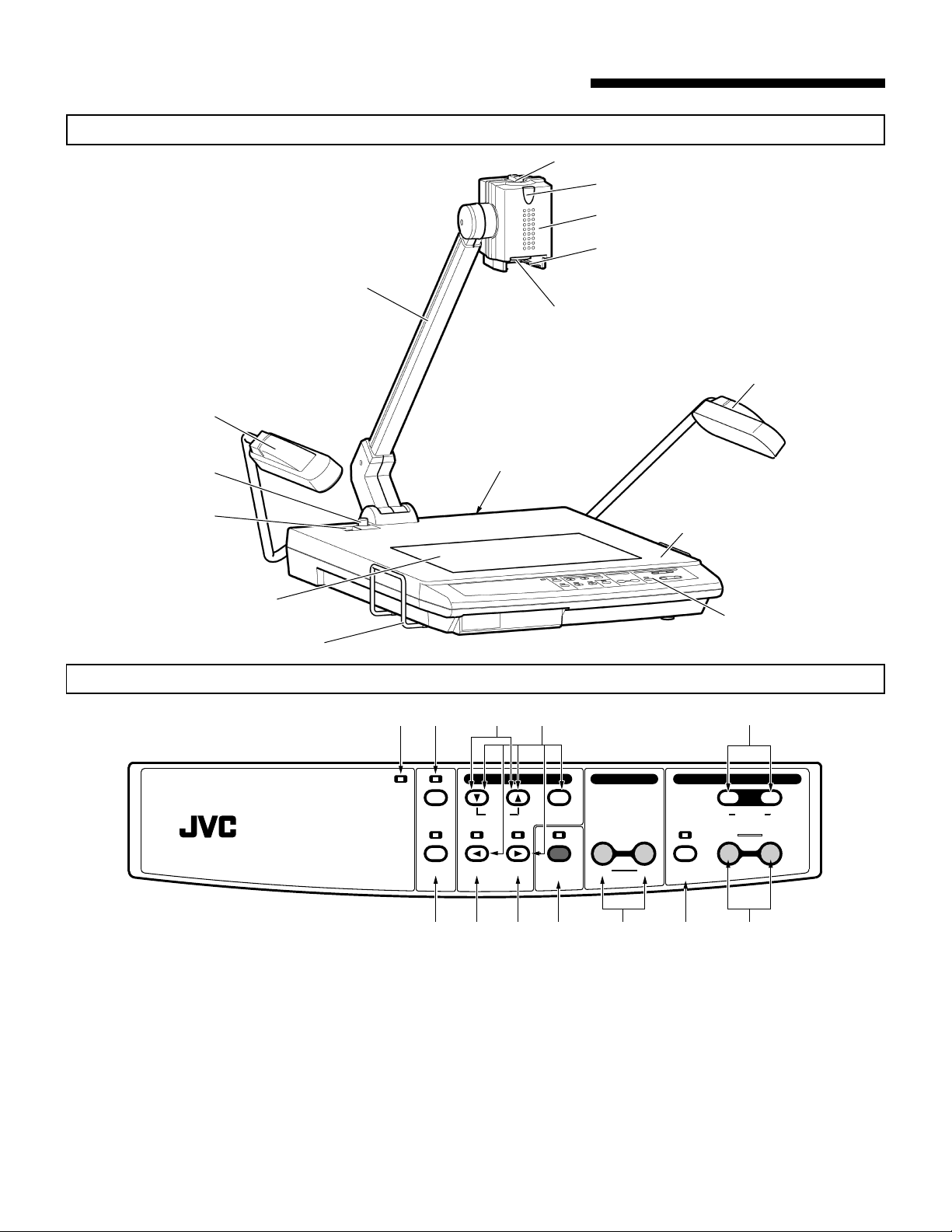
Main Unit
Camera head rotation knob
Camera arm
Close-up lens
Side Lamp
Remote control light reception section
Camera head
Slide film holder
Side Lamp
Lock release button
Power switch
Back illumination
Control Panel
Book holder
POWER
DIGITAL PRESENTER AV-P1000
Rear panel
@
!
ON-SCREEN ADJUSTMENTS
LIGHTS IRIS MENU/ENTER
VIDEO
PC FREEZE AUTO WHITE
OUT
Stage
Control panel
89
FARNEAR
SET
DIGITAL
2
ZOOMFOCUS
PRESET12
WIDETELE
356704
ZOOM buttons : Use to change picture size (p. 10).
1
PRESET buttons : Use to store frequently used picture sizes (p. 10).
2
DIGITAL ZOOM button : Use to change picture size electronically (p. 10).
3
FOCUS buttons : Use to focus on a specified point (p. 11).
4
AUTO WHITE SET button : Use to adjust white balance automatically (p. 11).
5
FREEZE button : Use to freeze an output picture (p. 11).
6
PC button : Use to switch between the camera picture input and the PC IN connector input (p. 12).
7
ON-SCREEN ADJUSTMENTS buttons : Use to adjust and set the camera (p. 14).
8
IRIS adjust buttons : Use to adjust picture brightness (p. 13).
9
VIDEO OUT button : Use to switch between RGB output and video output (p. 12).
0
LIGHTS button : Use to turn the side and back illumination on/off (p. 13).
!
Power indicator : when power is switched on it will glow green.
@
4
1
Rear panel
1 2 3
ABCD
2
3
4
1
1
0
SYNC.
RGB OUT1
REMOTE IN(RS-232C
MODE
R G B Hs/Cs Vs
4
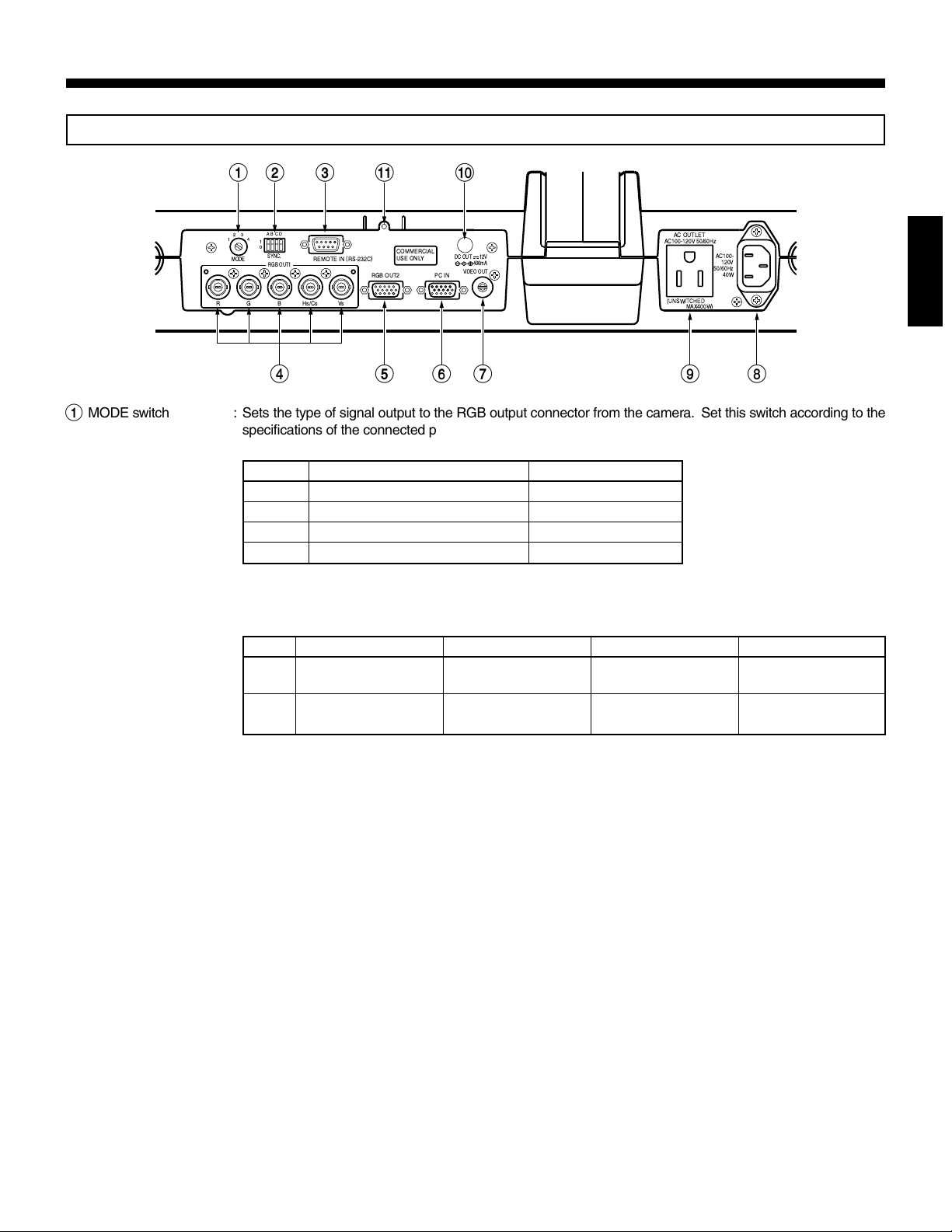
MODE switch : Sets the type of signal output to the RGB output connector from the camera. Set this switch according to the
1
! 0
AC OUTLET
AC100-120V 50/60Hz
(UNSWITCHED
MAX400W)
AC100-
120V
50/60Hz
40W
)
RGB OUT2
COMMERCIAL
USE ONLY
PC IN
DC OUT 12V
400mA
VIDEO OUT
5 6 7 9 8
specifications of the connected projector and display. When you want to change the mode, turn the unit off
and then turn it on again.
Mode Connected projector/display Output signal
1 SXGA (1280 x 1024) 1280 x 960 equivalent
2 XGA (1024 x 768) 1024 x 768 equivalent
3 SVGA (800 x 600) 800 x 600 equivalent
4 VGA (640 x 480) 640 x 480 equivalent
SYNC. switch : Use to set the mode for the sync signal output to the RGB output connectors or turn the on-screen display on/off.
2
* Mode 1 picture quality is high-
est. Mode 4 is lowest.
* When the mode is set to 2, 3
or 4, resolution will be reduced and picture quality may
be degraded.
Set this switch according to the specifications of the connected projector and display.
When you want to change the mode, turn the unit off and then turn it on again.
ABCD
Horizontal sync signals
1 Sync signals are not
are output.
Composite sync sig-
0 Sync signals are added
nals are output.
added to G signals.
to G signals.
On-screen signals are
output.
On-screen signals are
not output.
Unused
Unused
ENGLISH
A : Sets the type of sync signals output to the RGB OUT1 Hs/Cs connector and RGB OUT2 connector.
B : Sets whether or not sync signals are added to the video signal output at the RGB OUT1 G connector
and RGB OUT2 connector.
C : Sets whether or not the on-screen display signal is output to the video signal output at the RGB OUT1
and 2 connectors.
* On-screen signals are output to the VIDEO OUT connector regardless of the mode setting.
The default setting at the factory is: A = 1, B = 1, C = 1 and D = 1.
REMOTE IN connector : Connect a personal computer to this connector for remote PC operation (p. 18).
3
RGB OUT1 connectors: Output signals from the camera or PC IN connector and the sync signal (BNC connectors).
4
RGB OUT2 connector : Outputs signals from the camera or PC IN connector and the sync signal (D-sub 15 pins).
5
* The RGB OUT1 and OUT2 connectors output the same picture and sync signal at the same time.
PC IN connector : Input the RGB signal and sync signal from another device here. Signals can be output to the RGB OUT connectors.
6
Set the sync signal for the equipment connected to the PC IN connector according to the specifications
of the projector and display.
When connecting a personal computer, set its resolution to a suitable level.
VIDEO OUT connector : Outputs the video composite signal from the camera.
7
Use the VIDEO OUT button to switch between video output and RGB output.
Note:When video signals from the camera are output to the VIDEO OUT connector, no signal is output to
the RGB OUT connectors.
AC IN connector : Connect the power cord here.
8
AC outlet : Supplies power of up to 400 W regardless of the power switch setting.
9
DC OUT connector : Use this connector to supply DC power to the optional LCD monitor (TA-AV-Z7U).
0
LCD monitor holder : Use to mount the optional LCD monitor (TA-AV-Z7U). For installation, refer to the LCD monitor’s operating
!
instructions.
5
BEFORE USE
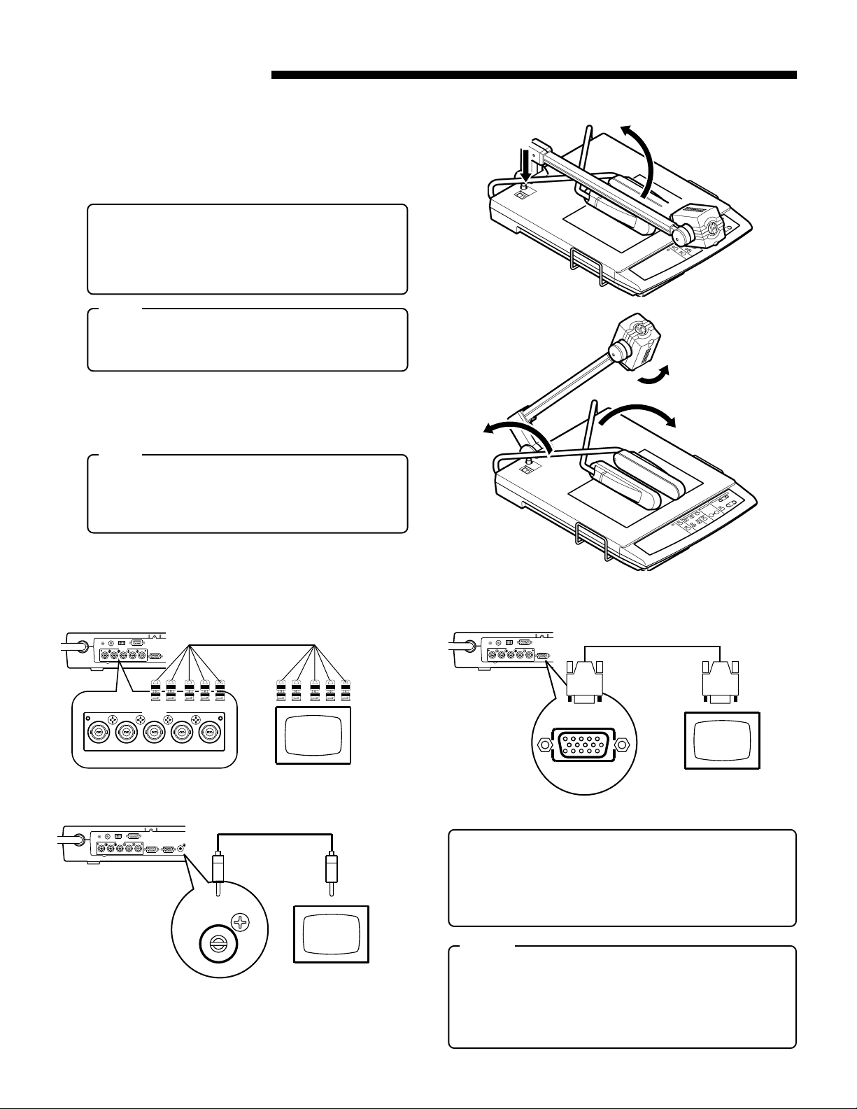
1.
While pressing down the lock release button 1 , hold the
camera arm with your hand and raise it in the direction
shown
release button.
Be sure to raise the camera arm until the lock release button is released and the camera arm is completely locked.
● To change the camera angle using the 5-position cam-
● Do not release the camera arm when the lock release
2.
To aim the camera head at the stage, turn it in the direction
shown
3.
Fold out the side illumination arms in the direction 4 .
● Do not move the side illumination arms in any direc-
. When the camera arm stops, release the lock
2
era arm function, press the lock release button again.
After changing the angle, fix the camera arm at the
position where the lock release button is released and
the camera arm is locked.
Note:
button is pressed. Otherwise, a malfunction or injury
may result.
until it clicks.
3
Note:
tion other than that shown
sive force to the lamps when changing the angle. Otherwise, a malfunction or electric shock may result.
. Do not apply exces-
4
4
1
2
3
4
4.
Check the type of input connector on the display or monitor
and make the appropriate connections.
● BNC Connection ● D-sub 15-pin Connection
ABCD
3
ABCD
3
2
4
1
1
0
SYNC.
)
REMOTE IN (RS-232C
MODE
RGB OUT1
R G B Hs/Cs Vs
RGB OUT1
R G B Hs/Cs Vs
RGB OUT2
RGB OUT1
BNC-BNC cable
To the RGB OUT1
connectors
To video input
connectors
2
4
1
1
0
SYNC.
REMOTE IN (RS-232C
MODE
RGB OUT1
RGBHs/CsVs
)
RGB OUT2
RGB OUT2
Display
● Composite Video Connection
ABCD
2
3
4
1
1
0
SYNC.
MODE
RGB OUT1
R G B Hs/Cs Vs
REMOTE IN (RS-232C
)
RGB OUT2 PC IN
VIDEO OUT
Provided video cable
To the VIDEO OUT
connector
To the video
input connector
* Use the shortest cable possible (3 m. max.) for RGB con-
nections.
Note: If the D-sub cable connector plugged into the RGB
OUT2 connector is too large, you won’t be able to con-
VIDEO OUT
nect a cable to the PC input connector.
Notes:
Monitor
5.
Connect the power cord connector to the AC IN connector
and plug the other end into an AC outlet. Press the power
switch to turn the power on.
● Be sure to turn the power off to protect this unit and other
connected equipment.
● Do not connect any device with more than the indicated
power (400 W) to the AC outlet. Doing so could result in
overheating and produce smoke or fire.
D-sub 15-pin cable
(Male)
To the RGB OUT2
connector
Display
(Male)
To the video
input connector
6
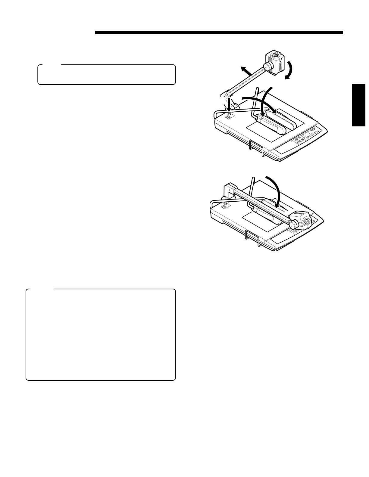
STORAGE
1.
Press the power switch off and unplug the power cord and
video cables.
Note:
● When plugging and unplugging the power cord and
video cables, hold the plugs.
3
2
2.
Fold in the left and right side illumination arms in the direction shown
wards the stage).
3.
Turn the camera head in the direction shown 2 until it stops.
4.
When moving the camera arm in the direction shown 3 ,
press the lock release button
arm down in the direction shown
Notes:
● Do not release the camera arm when the lock release but-
ton is pressed in. Otherwise, a malfunction or injury may
result.
● When the camera arm is locked, do not apply excessive
force to it. Otherwise, a malfunction may occur.
● For storage, do not lean this unit against a wall, etc. If it
falls over, a malfunction or injury may result.
● For transportation, do not hold the unit by camera arm, side
illumination (lamp or arm), book holder, etc. This could apply
excessive force to the unit, resulting in a malfunction or
injury. Only use the carrying handle to lift the unit.
(do not direct the side illumination lamps to-
1
. Then, fold the camera
4
until it stops and lock it.
5
4
1
1
ENGLISH
5
7
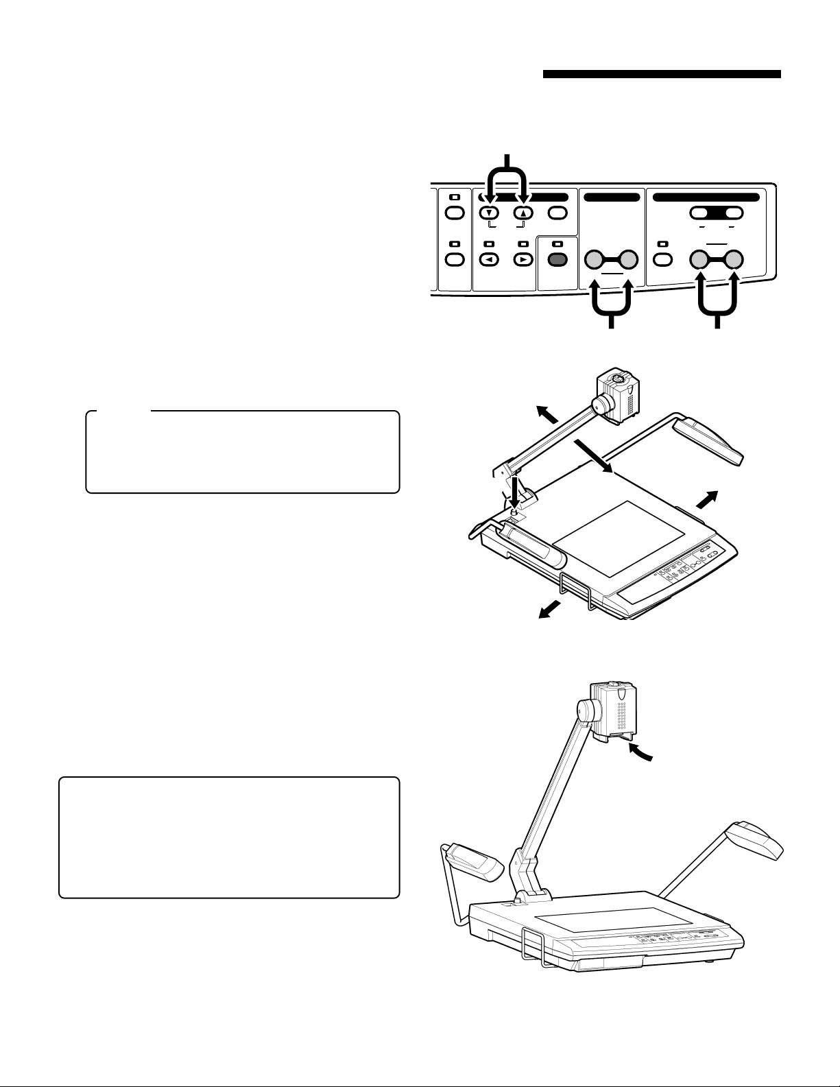
HOW TO MAKE PRESENTATIONS
1. Presenting material such as printed matter and 3-dimensional objects
● Put an object on the stage and adjust the picture size with
the ZOOM buttons
the picture size is determined, adjust the focus with the
FOCUS buttons
* When using in a room, it is recommended to turn on the
side illumination (for switching on the illumination, refer to
p. 13).
● When shooting a 3D object, use the 5-position camera arm
function to add presence to the picture.
While moving the camera arm in the direction shown 3,
press the lock release button
arm in the direction shown
button
● When capturing the image of a large object such as the
page of an encyclopedia, pull out the book holder in the
direction shown
to fix the arm at the lock position (5 steps).
4
while checking the screen. When
1
.
2
. Then, move the camera
4
and release the lock release
5
.
6
Notes:
● Do not apply excessive force to the book holder.
● Do not release the camera arm when the lock release
button is pressed. Otherwise, a malfunction or injury
may result.
!
ON-SCREEN ADJUSTMENTS ZOOMFOCUS
LIGHTS IRIS MENU/ENTER
VIDEO
PC FREEZE AUTO WHITE
OUT
SET
3
4
2
5
PRESET12
WIDETELE
FARNEAR
DIGITAL
1
6
2. Presenting slide films
Turn on the side illumination and insert the film into the slide
film holder
ZOOM buttons
just the focus with the FOCUS buttons
● To use the slide film holder, turn the side illumination on
and direct the fluorescent lamp down.
● If the slide film (vertical) is magnified until the mount sec-
tion can no longer be seen, focusing is not possible. Use
the zoom at the tele side.
● Do not put any objects on the stage.
. Then, adjust the size of the picture with the
7
. When the picture size is determined, ad-
1
.
2
6
7
8
3. Presenting transparent material such as an OHP sheet
Turn on the back illumination and put the transparent sheet
on the stage. Then, adjust the picture size with the ZOOM
buttons
focus with the FOCUS buttons
film, switch to the negative mode with the ON-SCREEN
ADJUSTMENTS (p. 14 and 15).
. When the picture size is determined, adjust the
1
. To present a negative
2
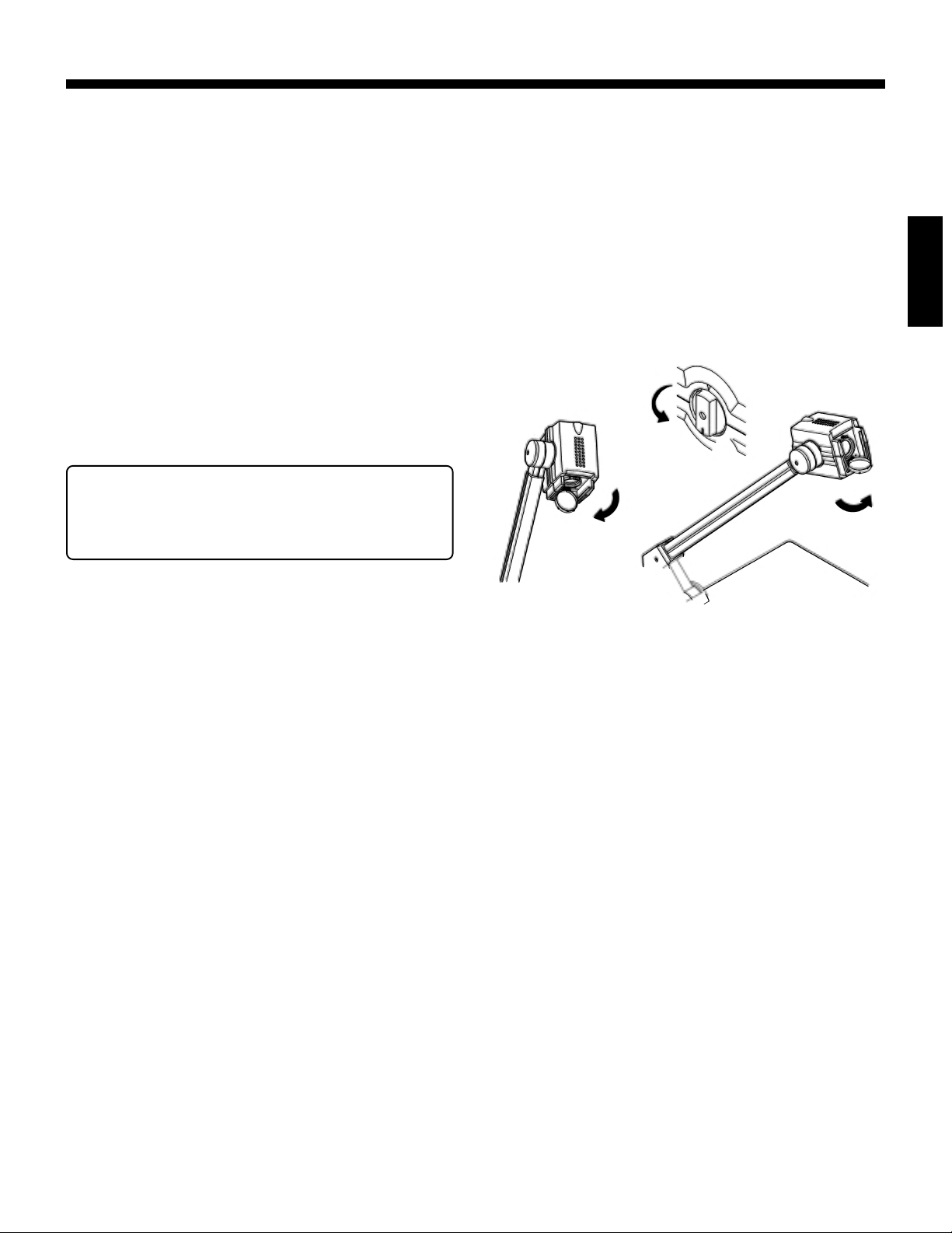
4. Shooting nearby objects
To shoot the face of a person or nearby objects such as a
blackboard, remove the close-up lens by turning it in the
direction shown
rection shown
180 degrees in the direction shown
insufficient, adjust with the IRIS buttons
● To shoot the stage, set the close-up lens and set the cam-
era head rotation knob to the original position.
● Be careful not to get fingerprints or dust on the close-up
lens.
. Then, direct the camera head in the di-
8
and turn the camera head rotation knob
9
. If the brightness is
0
.
!
8
ENGLISH
0
9
9
OPERATION
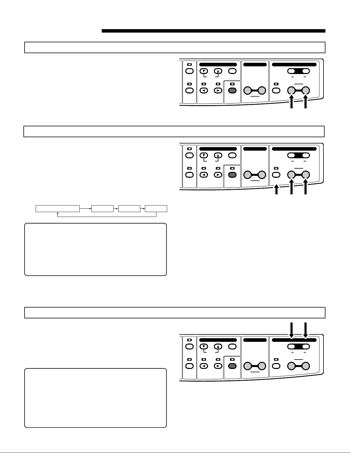
ZOOM
● Press the ZOOM TELE button to gradually enlarge the pic-
ture size and the ZOOM WIDE button to gradually reduce it.
● To increase the zooming speed, press the ZOOM button
continuously.
DIGITAL ZOOM
● This allows you to enlarge the picture size electronically.
● Pressing the DIGITAL ZOOM button enlarges the picture size
in increments from 2x to 3x, then 4x. The indicator lights.
● The picture size can be adjusted with the TELE or WIDE
button.
● Pressing the DIGITAL ZOOM button when the 4x picture is
displayed, returns the picture to its original size. The indicator goes off.
The indicator goes off.
Original picture 2 times 3 times 4 times
Lights up. Lights up. Lights up.
Press
ON-SCREEN ADJUSTMENTS ZOOMFOCUS
LIGHTS IRIS MENU/ENTER
VIDEO
PC FREEZE AUTO WHITE
OUT
ON-SCREEN ADJUSTMENTS ZOOMFOCUS
LIGHTS IRIS MENU/ENTER
VIDEO
PC FREEZE AUTO WHITE
OUT
SET
SET
PRESET12
WIDETELE
FARNEAR
DIGITAL
PRESET12
WIDETELE
FARNEAR
DIGITAL
* When the picture is enlarged electronically, resolution is low-
ered and noise appears.
* You can use the ON-SCREEN ADJUSTMENTS to change
the maximum magnification setting (p. 14 and 15).
Note : When video signals are output to the VIDEO OUT con-
nector, the picture cannot be enlarged with the digital
zoom function.
ZOOM PRESET
● Two frequently used picture sizes can be stored in memory.
● Set the required size and press the PRESET 1 or 2 button for
2 seconds or more. “P1” or “P2” appears in the upper left of
the display. When the preset information is stored, the indication goes out.
● To use one of the presets, press the PRESET 1 or 2 button.
* Preset data is retained when the power is turned off.
* Using the ON-SCREEN ADJUSTMENTS, the picture size
can be set from A4/LTR to A7/3 inches x 4 inches (p. 14 and
15). The initial setting is A4/LTR for PRESET 1 and A6/4 inches
x 6 inches for PRESET 2.
Note : The picture size cannot be preset when the FREEZE,
PICTURE MEMORY, or DIGITAL ZOOM function is
activated.
ON-SCREEN ADJUSTMENTS ZOOMFOCUS
LIGHTS IRIS MENU/ENTER
VIDEO
PC FREEZE AUTO WHITE
OUT
SET
PRESET12
WIDETELE
FARNEAR
DIGITAL
10
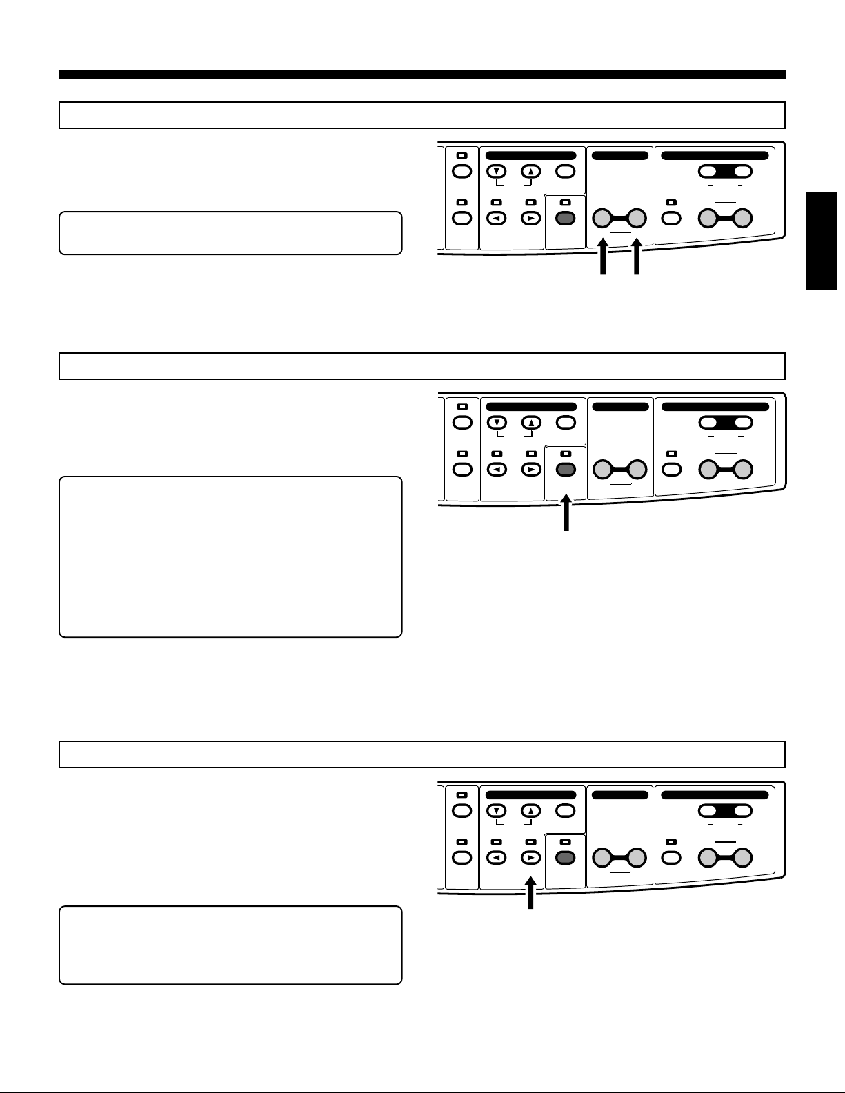
FOCUS
● Press the FOCUS buttons to adjust the focus.
● Press the NEAR button to focus on the upper (closer) part
of the object and the FAR button to focus on the lower
(farther) part.
Note : Focusing range is up to 100 mm from the stage sur-
face.
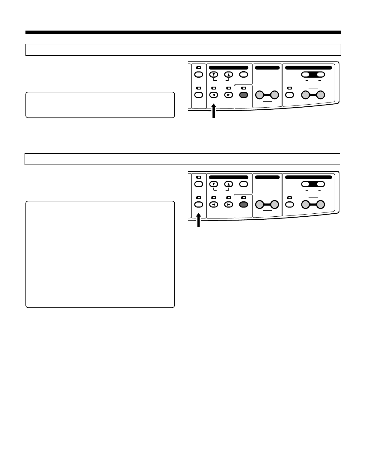
AUTO WHITE SET
● This adjusts the picture tone.
● Shoot a white sheet of paper in full screen and press the
AUTO WHITE SET button. The indicator blinks until the white
balance is set. When the white balance setting is complete,
the indicator stops blinking and remains lit.
* Even though the auto white set mode is engaged, the tone
is not adjusted unless this button is pressed.
* When the lighting changes, perform the auto white set op-
eration again.
* The auto white set mode and the manual mode can be switched
with the ON-SCREEN ADJUSTMENTS (p. 14 and 15).
Note : In the manual white balance mode, this button has no
effect. In this case, “MANUAL WB” is shown briefly in
the upper left of the screen for confirmation.
ON-SCREEN ADJUSTMENTS ZOOMFOCUS
LIGHTS IRIS MENU/ENTER
VIDEO
PC FREEZE AUTO WHITE
OUT
ON-SCREEN ADJUSTMENTS ZOOMFOCUS
LIGHTS IRIS MENU/ENTER
VIDEO
PC FREEZE AUTO WHITE
OUT
SET
SET
PRESET12
WIDETELE
FARNEAR
DIGITAL
ENGLISH
PRESET12
WIDETELE
FARNEAR
DIGITAL
FREEZE
● This freezes the picture from the camera and displays it as a
still image. The indicator lights.
● Press again to release the still mode. The indicator goes out.
● When the split mode is engaged using the ON-SCREEN AD-
JUSTMENTS, the screen is divided. The still picture is shown
on one side and the current camera picture on the other. The
indicator blinks.
* For the split mode setting, refer to p. 14 and 15.
Note : When the still mode is engaged, zoom, focus and iris
adjustments are not possible. Also, the VIDEO OUT
button has no effect.
ON-SCREEN ADJUSTMENTS ZOOMFOCUS
LIGHTS IRIS MENU/ENTER
VIDEO
PC FREEZE AUTO WHITE
OUT
SET
PRESET12
WIDETELE
FARNEAR
DIGITAL
11
PC
● Use this button to output the PC signal (input from the PC IN
connector) to the RGB OUT connectors. The indicator lights.
● Press the button again to restore camera picture output. The
indicator goes out.
Note : Depending on the projector or display, the picture may
be distorted or it may take some time before the picture
appears after the signal is switched with this button.
VIDEO OUT
● Press this button to output composite signals from the cam-
era to the VIDEO OUT connector. The indicator lights.
● Press again to output signals to the RGB OUT connectors.
The indicator goes out.
Notes: ● Signals received via the PC IN connector cannot
be output to the VIDEO OUT connector.
● Thin lines in the camera picture may flicker on the
monitor screen when the camera signal is output
via the VIDEO OUT connector.
● When digital zoom is activated, signals cannot be
output to the VIDEO OUT connector.
● During video output, the [FREEZE] button will not
operate.
● During video output, the [PICTURE MEMORY 1
to 3] buttons will not operate.
* Camera signals can be output from the VIDEO OUT con-
nector at the same time as signals from the PC IN connector are output from the RGB OUT connectors.
ON-SCREEN ADJUSTMENTS ZOOMFOCUS
LIGHTS IRIS MENU/ENTER
VIDEO
PC FREEZE AUTO WHITE
OUT
ON-SCREEN ADJUSTMENTS ZOOMFOCUS
LIGHTS IRIS MENU/ENTER
VIDEO
PC FREEZE AUTO WHITE
OUT
SET
SET
PRESET12
WIDETELE
FARNEAR
DIGITAL
PRESET12
WIDETELE
FARNEAR
DIGITAL
12
 Loading...