

Page 1
- 1 -
D
K
A
E
U
N
Apppplliiccaattiioonn
A
Noottee
N
Intelligent Assembly Solutions
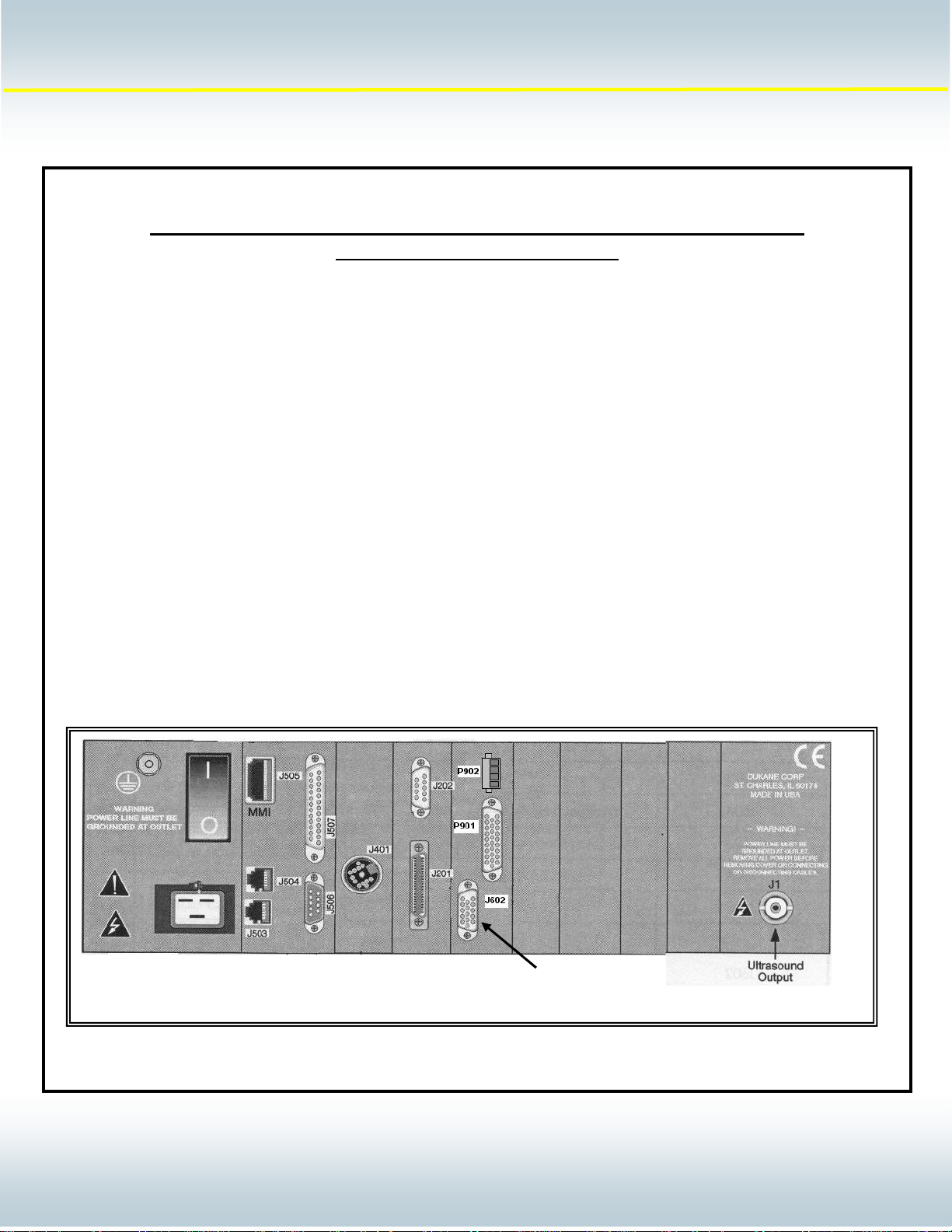
The DPC 4 welding system offers several features that are intended to communicate with automation. These features
allow the automation to control and respond to events that occur during the welding process. This document will provide
guidelines that will help you interface automation to a DPC welding system per Dukane Corporation’s requirements.
Information within this document is intended to supplement the information in the DPC 4 manual (Dukane part # 403-557).
Automation Interface Requirements for J602 Basic I/O Interface
of a DPC 4 Welding System
Note: Early production models of the DPC IV welding system referred to J602 as the User I/O interface. The
functionality of the Basic I/O Interface and the User I/O Interface are identical. Only the name has changed.
Application Note Topics:
• The J602 Pin assignments
• The 200-1203 Basic Interface Cable
• Status Output Signal Descriptions
• Status Output Interface Examples
• System Input Signal Descriptions
• System Input Interface Examples
Basic I/O
Interface
AN400
© Dukane Corporation 2004. All rights reserved.
Dukane Corporation
2900 Dukane Drive Saint Charles, IL 60174 USA
Phone (630) 797-4900 FAX (630) 797-4949
http://www.dukane.com/us
11101
1
Page 2
- 2 -
D
K
A
E
y
d
)
)
d
U
N
Apppplliiccaattiioonn
A
Noottee
N
Intelligent Assembly Solutions
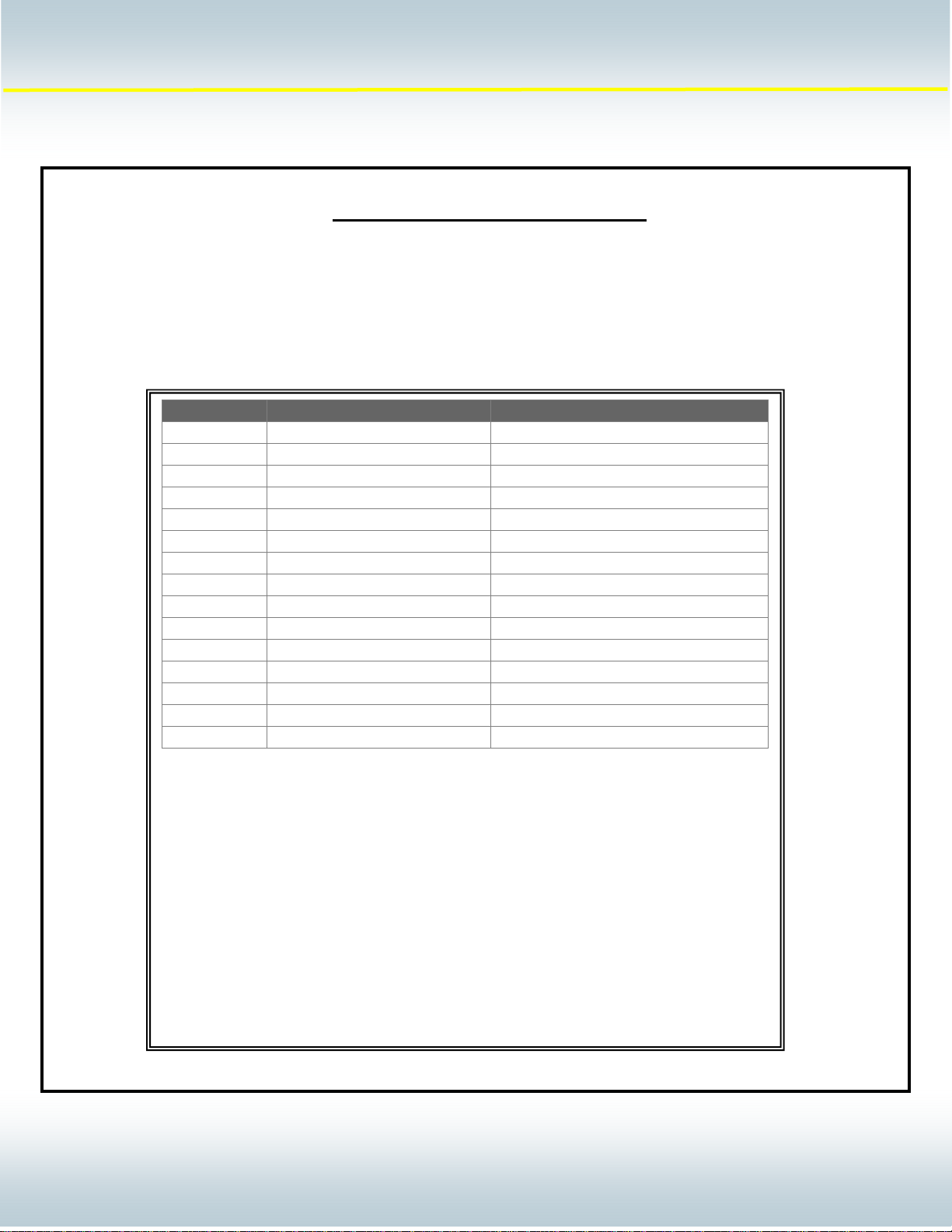
The J602 User Interface connector is the primary communications link between the DPC IV and user automation
equipment. This connector provides status signals that can be used to monitor DPC weld data analysis resu lts as well
as timing issues related to the processing of the weld sequence. It also provides the automation with dedicated
communication lines that allows the automation to control the beginning and the end of a welding sequence.
Pin Number DPC Signal Name DPC Signal Type
1 Power Suppl
2 Groun
3 Bad Part Output
4 Suspect Part (see note #2
5 Good Part Output
6 Ready (see note #1
7 Isolated Output Common Common Pin for Output Signals
8 Automation Input Input
9 Automation Stop N/C Input
10 Automation Stop N/O Input
11 Hand Probe Press Inhibit Input
12 Input Common Common Pin for Input Signals
13 Groun
14
15 Ground Detect Input
Note #1: This input can be reconfigured in the DPC IV menu choices to activate during
the following weld sequence event:
In Cycle
Sonics On
In Hold
Note #2: This input can be reconfigured in the DPC IV menu choices to activate during
the following weld sequence event:
Network Active
Sonics On
Note: Please refer to the Hardware Setup section of the DPC IV manual for details on
reconfiguring pin 4 or pin 6 to the required status output signal.
J602 User Interface Connector
+22 VDC (0.5 amp max)
Power Supply Return
Output
Output
Power Supply Return
AN400
© Dukane Corporation 2004. All rights reserved.
Dukane Corporation
2900 Dukane Drive Saint Charles, IL 60174 USA
Phone (630) 797-4900 FAX (630) 797-4949
http://www.dukane.com/us
22102
2
Page 3
- 3 -
D
K
A
E
U
N
Apppplliiccaattiioonn
A
Noottee
N
Intelligent Assembly Solutions
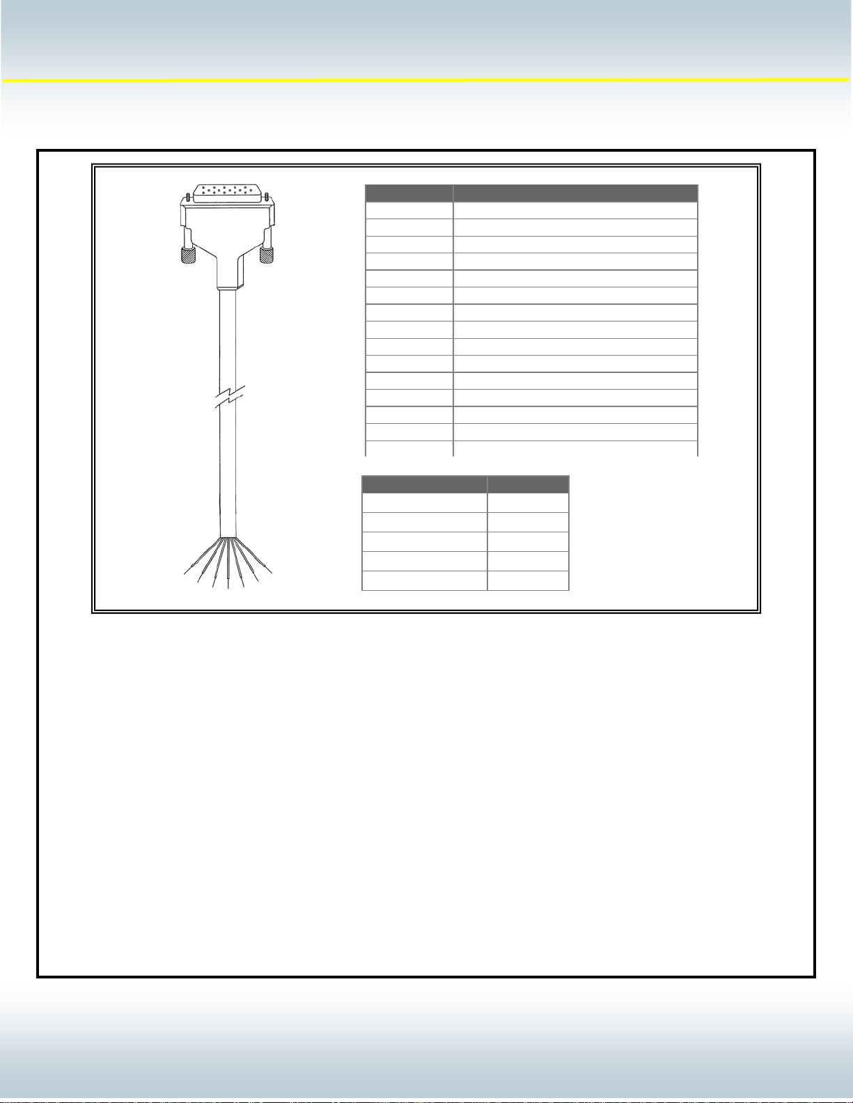
Status Output signals for the J602 Connector:
There are four status output signals available on the J602 connector. Each of these outputs are driven by a solid state
relay that creates a switch closure between the specified output pin and the Output Common pin. These pins can be
configured within the DPC software menus to provide a signal that accommodates the requirements of most automation
interface equipment. The available configurations for these output signals are:
Note: Please refer to the Hardware menu section of the DPC IV manual for further information on these features.
Active High Outputs – This setting will produce a closed switch condition between the spe cified outp ut pin and
the Output Common pin when the output signal is activated. (Factory default setting)
Active Low Outputs - This setting will produce an open switch condition between the specified output pin and
the Output Common pin when the output signal is activated.
Maintained Outputs - This setting will produce an output signal that is maintained from the completion of a
welding cycle until the beginning of the next welding cycle activation. (Factory default
setting)
Pulsed Outputs - This setting will produce an output signal that is pulsed a single time for 100 mS as the
end of the welding cycle.
Pin # Conductor Color
1 Red
2 Black
3 Blue / Black
4 Green / White
5 Blue / White
6 Red / Black
7 White / Black
8 White
9 Orange
10 Blue
11 Orange / Black
12 Red / White
13 Green Black
14 Black / White
15 Green
Part Number Length
200-1203 10 FT
200-1203-15 15 FT
200-1203-20 20 FT
200-1203-25 25 FT
200-1203-30 30 FT
AN400
© Dukane Corporation 2004. All rights reserved.
Dukane Corporation
2900 Dukane Drive Saint Charles, IL 60174 USA
Phone (630) 797-4900 FAX (630) 797-4949
http://www.dukane.com/us
33103
3
Page 4

- 4 -
D
K
A
E
U
N
Apppplliiccaattiioonn
A
Noottee
N
Intelligent Assembly Solutions
Status Output Signal Descriptions:
Bad Part Output – (J602 pin 3) This status output will activate when the data acquired during the welding sequence
exceeds one of the user defined boundaries within the Bad Part Limits portion of the user setup.
Please refer to the Process Limits section of the DPC IV manual for further details on selecting
and setting up a Bad Part Limit window.
Good Part Output - (J602 pin 5) This status output will activate when the data acquired during the welding sequence
does not exceed any of the user defined boundaries within the Bad Part Limits portion of the user
setup. Please refer to the Process Limits section of the DPC IV manual for further details on
selecting and setting up a Bad Part Limit window.
Suspect Part Output - (J602 pin 4) This status output will activate when the data acquired during the welding sequence
exceeds one of the user defined boundaries within the Suspect Part Limits portion of the user
setup. Please refer to the Process Limits section of the DPC IV manual for further details on
selecting and setting up a Suspect Part Limit window.
In Cycle (J602 pin 4 redefined) - This status output will activate when the welding cycle begins. If
the status outputs have been set for maintained, In Cycle will deactivate when the Hold portion of
the welding cycle has completed. Please refer to the Hardware Setup section of the DCP IV
manual for further details on redefining J602 pin 4.
Sonics On (J602 pin 4 redefined) – This status output will activate when the DP C produces the
ultrasound welding signal that creates motion in the transducer stack assembly. Activation of this
signal will occur during the Weld, Scrub, and Afterburst portions of the weld cycle. Please refer to
the Hardware Setup section of the DCP IV manual for further details on redefining J602 pin 4.
In Hold (J602 pin 4 redefined) – This status output will activate when the DPC is processing the
Hold portion of the welding cycle. Please refer to the Hardware Setup section of the DCP IV
manual for further details on redefining J602 pin 4.
Ready Output - (J602 pin 6) This status output will activate at the completion of the Hold portion of the welding
sequence. It should be noted that the activation of the Afterburst feature and the return of the
pneumatic press to the home position will occur after the activation of the Ready Output status
signal. Please refer to the Process Control section of the DPC IV manual for further information
on the activation and use of the Afterburst feature. In addition please refer to the Hardware Setup
section of the DCP IV manual for further details on redefining J602 pin 6.
Network Active (J602 pin 6 redefined) – This status output will activate when the DPC is an active
node on a DPC network. Please refer to the Network section of the DPC IV manual for further
details on setting up a DPC network. Please refer to the Hardware Setup section of the DCP IV
manual for further details on redefining J602 pin 6.
Sonics On (J602 pin 6 redefined) – This status output will activate when the DPC produces the
ultrasound welding signal that creates motion in the transducer stack assembly. . Please refer to
the Hardware Setup section of the DCP IV manual for further details on redefining J602 pin 6.
AN400
© Dukane Corporation 2004. All rights reserved.
Dukane Corporation
2900 Dukane Drive Saint Charles, IL 60174 USA
Phone (630) 797-4900 FAX (630) 797-4949
http://www.dukane.com/us
44104
4
Page 5
- 5 -
D
K
A
E
y
U
N
Apppplliiccaattiioonn
A
Noottee
N
Intelligent Assembly Solutions
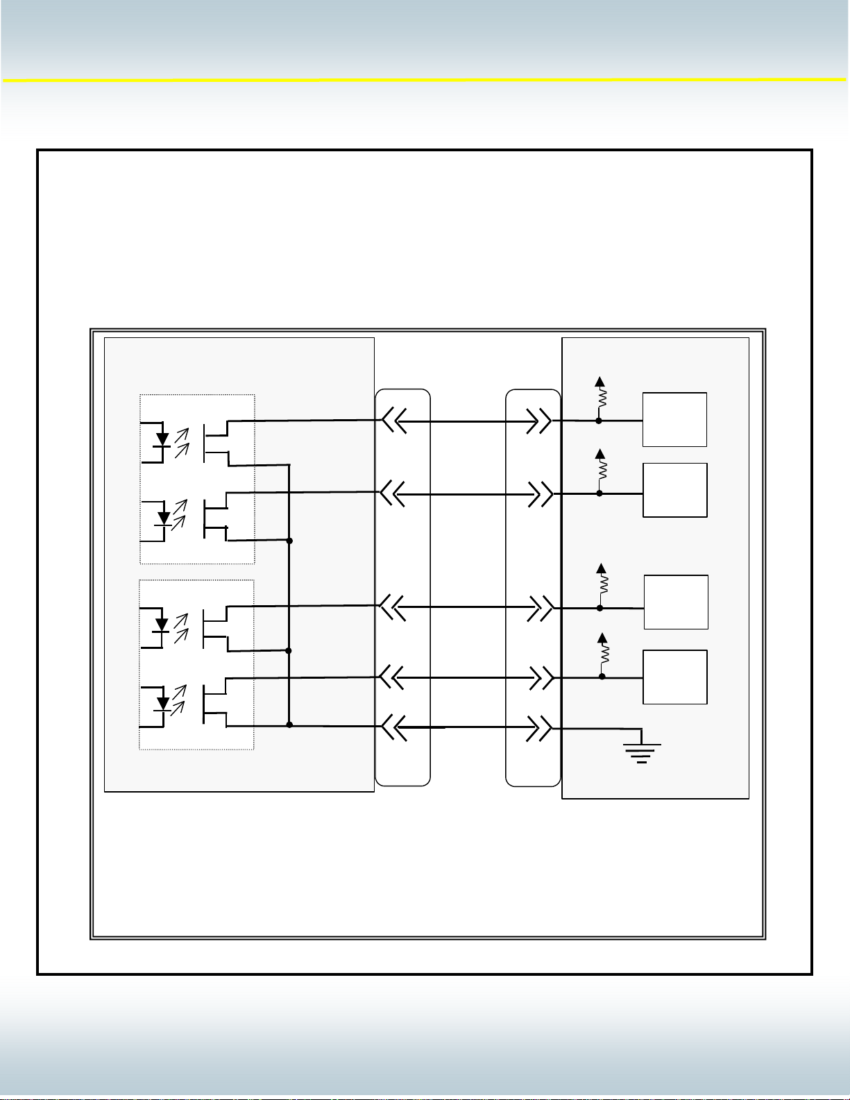
The DPC status output pins can be configured to adapt to several types of automated devices. The ratings for the DPC
Status output pins are:
Maximum Voltage Rating = +24 VDC
Maximum Current Rating = 100 mA
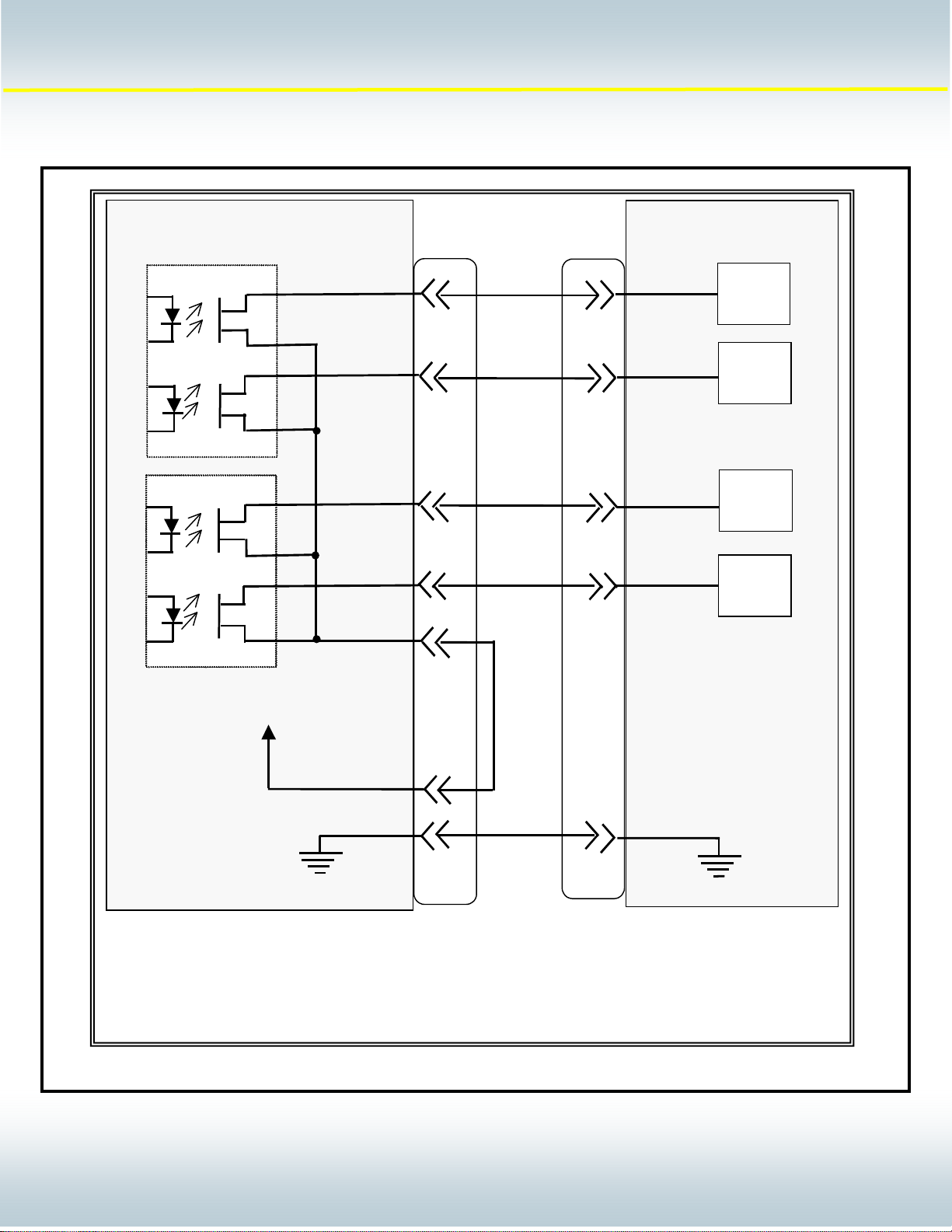
Status Output Interface Examples:
DPC IV
Bad Part
Suspect
Part
3
4
+ 24 VDC
Input
Device
Input
Device
AN400
Good Part
Read
Output
Common
DPC IV status output configuration for use with a PLC requiring sinking inputs.
5
6
7
J602
200-1203
Cable
Input
Device
Input
Device
PLC
© Dukane Corporation 2004. All rights reserved.
Dukane Corporation
2900 Dukane Drive Saint Charles, IL 60174 USA
Phone (630) 797-4900 FAX (630) 797-4949
http://www.dukane.com/us
55105
5
Page 6
- 6 -
D
K
A
E
U
N
Apppplliiccaattiioonn
A
Noottee
N
Intelligent Assembly Solutions
DPC IV
Bad Part
Suspect
Good Part
Part
AN400
3
4
5
Input
Device
Input
Device
Input
Device
Ready
Output
Common
+ 22 VDC
Power Supply
Ground
DPC IV status output configuration for use with a PLC requiring sourced inputs.
6
7
J602
Input
Device
1
2
PLC
200-1203
Cable
© Dukane Corporation 2004. All rights reserved.
Dukane Corporation
2900 Dukane Drive Saint Charles, IL 60174 USA
Phone (630) 797-4900 FAX (630) 797-4949
http://www.dukane.com/us
66106
6
Page 7

- 7 -
D
K
A
E
y
y
U
N
Apppplliiccaattiioonn
A
Noottee
N
Intelligent Assembly Solutions
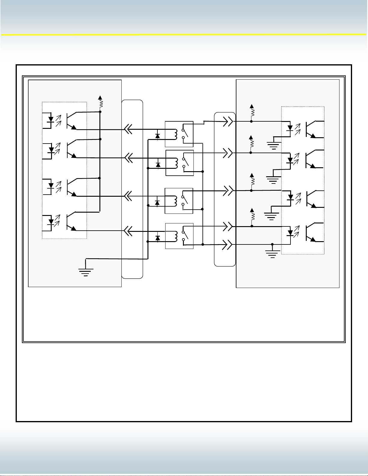
DPC IV
Good Part
Bad Part
Suspect
Part
AN400
3
Customer
Device
4
Customer
Device
5
Customer
Device
J602
6
Customer
7
1
2
200-1203
Cable
Device
Read
Output
Common
+ 22 VDC
Power Supp l
Ground
DPC IV status output configuration for use when either isolation is required or
the customer device exceeds the maximum ratings of the DPC outputs.
© Dukane Corporation 2004. All rights reserved.
Dukane Corporation
2900 Dukane Drive Saint Charles, IL 60174 USA
Phone (630) 797-4900 FAX (630) 797-4949
http://www.dukane.com/us
77107
7
Page 8

- 8 -
D
K
A
E
U
N
Apppplliiccaattiioonn
A
Noottee
N
Intelligent Assembly Solutions
System Input signals for the J602 Connector:
There are four system input signals available on the J602 connector. Each of these inputs are configured as sinking
inputs ( Do not apply voltage to the J602 inputs).
Automation Input - (J602 pin 8) This system input signal is activated by an external dry contact closure to the DPC
Ground pin on J602 pin2). The minimum duration for the activation of this input is 100 mS. The
maximum duration of this input is determined by the duration of the weld cycle. This input should
be deactivated before the end of the weld cycle to avoid an error condition (Associated Error: #
212 Auto Active at Cycle Start). Please refer to the Initiate Mode section of the DPC IV manual
for details on the activation and use of the Auto Initiate mode.
Automation Stop N/O- (J602 pin 9) This system input signal is activated by an external dry contact closure to the DPC
Ground pin on J602 pin2). The minimum duration for the activation of this input is 100 mS.
Activation of this input will end the welding cycle and deactivate all valves in the press. This
system response will continue until the contact closure to the DPC ground is removed. Weld
cycles that have been stopped due to the activation of this input will not be counted in the part
count value displayed on the DPC. Please refer to the Initiate Mode section of the DPC IV
manual for details on the activation and use of the Automation Stop mode (Auto Abort).
Automation Stop N/C- (J602 pin 10) This system input signal is activated by an removing an external dry contact closure
to the DPC Ground pin on J602 pin2). The minimum duration for the activation of this input is 100
mS. Activation of this input will end the welding cycle and deactivate all valves in the press. This
system response will continue until the contact closure to the DPC ground is replaced. Weld
cycles that have been stopped due to the activation of this input will not be counted in the part
count value displayed on the DPC. Please refer to the Initiate Mode section of the DPC IV
manual for details on the activation and use of the Automation Stop mode (Auto Abort).
Hand Probe Press Inhibit - (J602 pin 11) This system input is activated by an external dry contact closure to the DPC
Ground pin on J602 pin2). The minimum duration for the activation of this input is 100 mS.
Activation of this input is intended to configure the DPC for a probe system functionality. It will
deactivate all valves for the press during a welding cycle. This system response will continue until
the contact closure to the DPC ground is removed.
AN400
© Dukane Corporation 2004. All rights reserved.
Dukane Corporation
2900 Dukane Drive Saint Charles, IL 60174 USA
Phone (630) 797-4900 FAX (630) 797-4949
http://www.dukane.com/us
88108
8
Page 9

- 9 -
D
K
A
E
A
A
A
U
N
Apppplliiccaattiioonn
A
Noottee
N
Intelligent Assembly Solutions
The DPC system inputs are configured for a dry contact closure activation. The following connection diagram indicates
how to interface automation to the system inputs.
System Input Interface Examples:
PLC
200-1203
Cable
8
9
+ 24 VDC
uto Initiate
utomation Stop
N/O
AN400
10
utomation Stop
11
Hand Probe
2
Output
Common
DPC IV system input configuration for use when customer equipment provides contact
closure signals with not voltage.
J602
Press Inhibit
DPC IV
© Dukane Corporation 2004. All rights reserved.
Dukane Corporation
2900 Dukane Drive Saint Charles, IL 60174 USA
Phone (630) 797-4900 FAX (630) 797-4949
http://www.dukane.com/us
99109
9
Page 10
- 10 -
D
K
A
E
A
A
A
/C
U
N
Apppplliiccaattiioonn
A
Noottee
N
Intelligent Assembly Solutions
PLC
+ 24 VDC
200-1203
Cable
AN400
DPC IV
+ 24 VDC
8
uto Initiate
9
utomation Stop
N/O
10
utomation Stop
N
11
2
Output
Common
DPC IV system input configuration for use when customer equipment sources
voltage to the DPC inputs.
Hand Probe
Press Inhibit
J602
© Dukane Corporation 2004. All rights reserved.
Dukane Corporation
2900 Dukane Drive Saint Charles, IL 60174 USA
Phone (630) 797-4900 FAX (630) 797-4949
http://www.dukane.com/us
10101010
10
 Loading...