

Dukane 9100WUSS User Manual
®
DLP
Projector
9100WUSS
User's Manual (detailed)
Operating Guide
Thank you for purchasing this projector.
WARNING
Be sure to read Safety Guide rst. After reading them, store them in a safe
place for future reference.
►Before using this product, read all manuals for this product.
About this manual
Various symbols are used in this manual. The meanings of these symbols are
described below.
WARNING
CAUTION
NOTICE This entry notices of fear of causing trouble.
NOTE
• The illustrations in this manual are for illustrative purposes. They may differ
slightly from your projector.
• The manufacturer assumes no responsibility for any errors that may appear in
this manual.
• The reproduction, transfer or copy of all or any part of this document is not
permitted without express written consent.
• The information in this manual is subject to change without notice.
This symbol indicates information that, if ignored, could possibly
result in personal injury or even death due to incorrect handling.
This symbol indicates information that, if ignored, could possibly
result in personal injury or physical damage due to incorrect handling.
Refer to the pages written following this symbol.
9100WUSS-User-manual-00
1

Contents
Introduction ...............3
Checking the contents of package
Part names ....................4
Projector, Control panel and Indicators,
Ports, Remote control
Setting up .................8
Installing the lens unit ............9
Arrangement ..................10
Connecting with your devices .....13
Using the security slot ...........18
Installation of the projector ....... 19
Remote control ...........21
Installing the batteries ...........21
Using the REMOTE ID function. . . .22
About the remote control signal ...23
Power on/off ..............24
Turning on the power ........... 24
Turning off the power ........... 24
Operating ................25
Selecting an input signal .........25
Selecting an aspect ratio .........26
Adjusting the projector's angle,
Lens Shift, Zoom, Lens Centering,
and Focus
...................27
Using the automatic adjustment feature
Other buttons ..................30
Correcting the distortion ......... 31
Using the EDGE BLENDING features
Using the magnify feature ........38
Temporarily freezing the screen ...39
Temporarily blanking the screen ...39
PbyP (Picture by Picture) /
PinP (Picture in Picture) . . 40
Using the menu function .........44
Indication in OSD,
Containing items of each menu
EASY MENU. . . . . . . . . . . . . . . 47
PICTURE menu ............48
IMAGE menu ..............52
INPUT menu ..............53
SETUP menu ..............54
SCREEN menu .............57
OPTION menu .............58
NETWORK menu ...........62
....3
. . 30
. . 34
Web Control ...............65
Maintenance ..............67
Cleaning the ventilation inlet ..... 67
Other care ....................68
Troubleshooting ...........70
Related messages .............70
Regarding the indicator ......... 71
Resetting all settings ............72
Phenomena that may be easy to
be mistaken for machine defects
. . 73
Specications .............79
2

Introduction
Introduction
Checking the contents of package
See the Contents of package section in the User’s Manual (booklet). Your
projector should come with the items shown there. Require of your dealer
immediately if any items are missing.
WARNING
to put in the mouth. If swallowed, consult a physician immediately for emergency
treatment.
NOTE
to use the original packing materials when moving the projector. Use special
caution for the lens.
• Keep the original packing materials for future reshipment. Be sure
►Keep small parts away from children and pets. Take care not
3
Introduction
Part names
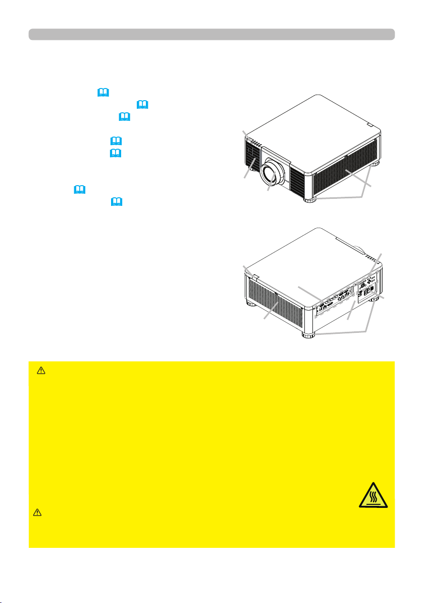
Projector
(1) Mount cap (
(2) Adjustable foot (x4) (27)
(3) Remote sensor (23, 61)
(4) Ventilation inlet
(5) Control panel (5)
(6) AC (AC inlet) (19)
(7) Ventilation inlet
(8) Ventilation outlet
(9) Ports (6)
(10) Security slot (18)
19)
(3)
(4)
(7)
(1)
(2)
(5)
(3)
(9)
(6)
WARNING
(8)
►Do not open or remove any portion of the product, unless
(10)
(2)
the manuals direct it.
►Do not subject the projector to unstable conditions.
►Do not apply a shock or pressure to this product. Remove all the attachments
including the power cord and cables, from the projector when carrying the
projector.
►Do not look into the lens and the openings on the projector while the light
source is on since the projection ray may cause a trouble on your eyes.
►Keep any object away from concentrated projection light beam. Blocking the
beam by something causes high temperature and could result in re or smoke.
►Do not touch around the ventilation outlet during use or just after use,
since it is too hot.
CAUTION
►Do not attach anything onto the lens except the lens
cover of this projector because it could damage the lens, such as melting the
lens.
(continued on next page)
4
Part names (continued)
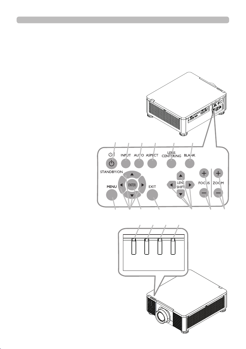
Control panel and Indicators
(1) STANDBY/ON button
(2) INPUT button
(3) AUTO button
(4) ASPECT button
(5) LENS CENTERING button
(6) BLANK button
(7) MENU button
(8) ▲/▼/◄/► cursor buttons
(9) ENTER button
(10) EXIT button
(11) LENS SHIFT button
(12) FOCUS button
(13) ZOOM button
(14) POWER indicator
(15) STATUS indicator
(16) LIGHT indicator
(17) TEMP. indicator
Introduction
(1) (2) (3) (4) (5) (6)
(continued on next page)
(7) (8) (9) (10) (11) (12) (13)
(17) (16) (15) (14)
TEMP.
LIGHT
STATUS
POWER
5
Introduction
Part names (continued)
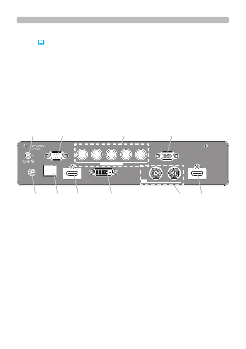
Ports (13~17)
(1) COMPUTER IN1 port
(2) COMPUTER IN2 port
(3) CONTROL port
(4) HDBaseT/LAN port
(5) HDMI 1 port
(6) HDMI 2 port
(7) DVI-D port
(8) SDI IN/OUT port
(9) REMOTE CONTROL port
(10) 12V OUTPUT (OPTION) port
(10) (3) (2) (1)
CONTROL V H
LAN
REMOTE
CONTROL HDBaseT HDMI1 DVI-D HDMI2
COMPUTERIN2
G/Y R/Cr/Pr COMPUTERIN1
B/Cb/Pb
IN OUT
SDI
(9) (4) (5) (7) (8) (6)
(continued on next page)
6
Part names (continued)
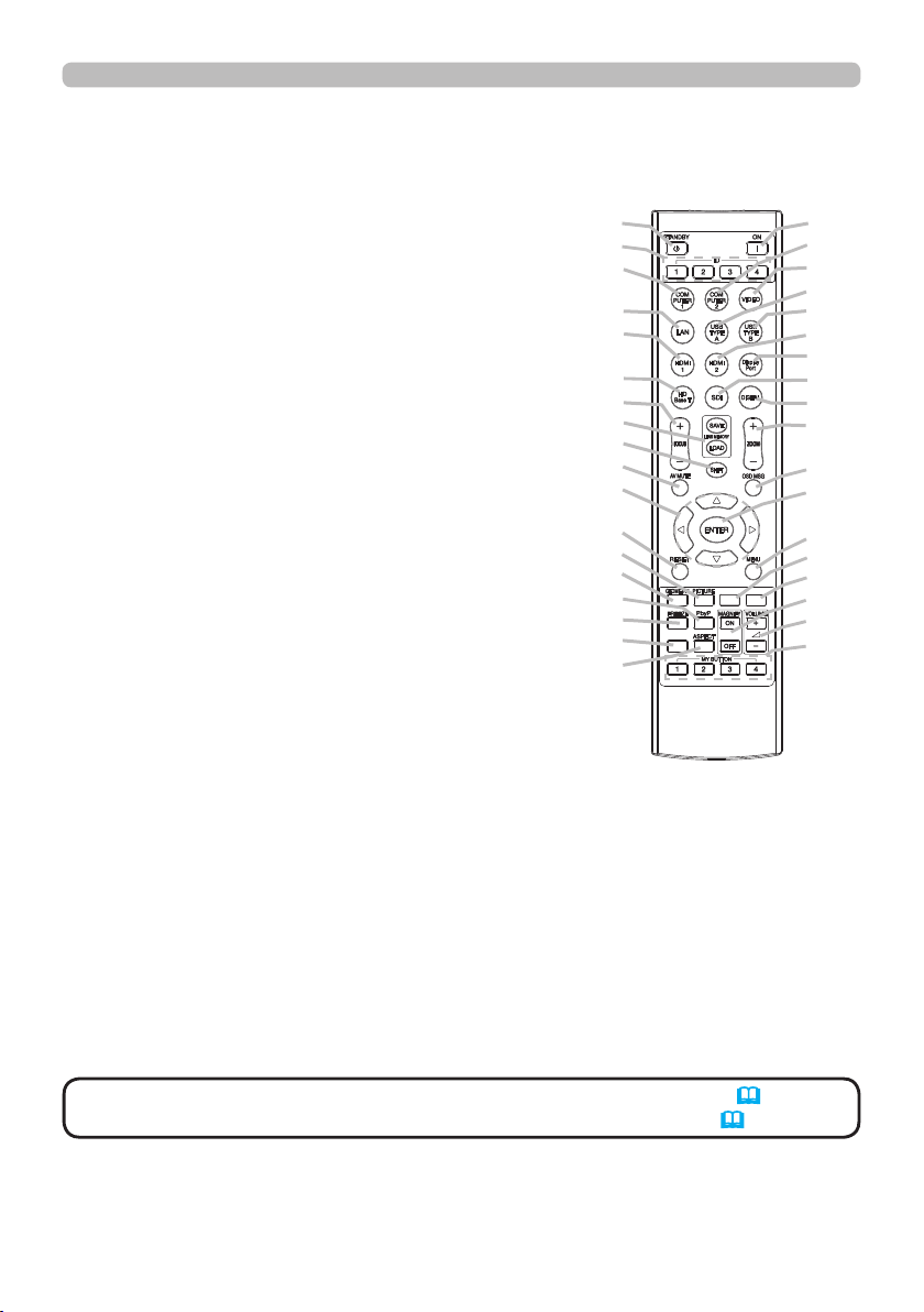
Remote control
(1) STANDBY button
(2) ON button
(3) VOLUME + / - buttons *
(4) AV MUTE button
(5) COMPUTER 1 button
(6) COMPUTER 2 button
(7) VIDEO button *
(8) LAN button *
(9) USB TYPE A button *
(10) USB TYPE B button *
(11) HDMI 1 button
(12) HDMI 2 button
(13) Display Port button *
(14) HDBaseT button
(15) SDI button
(16) DIGITAL button
(17) FOCUS + / - button
(18) LENS MEMORY SAVE / LOAD button
(19) SHIFT button
(20) ZOOM + / - buttons
(21) GEOMETRY button
(22) ASPECT button
(23) PICTURE button
(24) FREEZE button
(25) PbyP button
(26) MAGNIFY ON / OFF buttons
(27) MY BUTTON - 1 / 2 / 3 / 4 buttons
(28) MENU button
(29) RESET button
(30) ENTER button
(31) ▲/▼/◄/► cursor buttons
(32) ID-1 / 2 / 3 / 4 buttons
(33) OSD MSG button
(34) NETWORK button
(35) INTERACTIVE button *
(36) INFO button
(1)
(32)
(5)
(8)
(11)
(14)
(17)
(18)
(19)
(4)
(31)
(29)
(23)
(21)
(25)
(24)
(36)
(22)
INFO
Introduction
(2)
(6)
(7)
(9)
(10)
(12)
(13)
(15)
(16)
(20)
(33)
(30)
(28)
(34)
(35)
INTERACTIVE
NETWORK
(26)
(3)
(27)
NOTE
• Any button marked with “*” is not supported on this projector (70).
• Some keys are unavailable when OSD MESSAGE is set to INHIBIT(
56).
7
Setting up
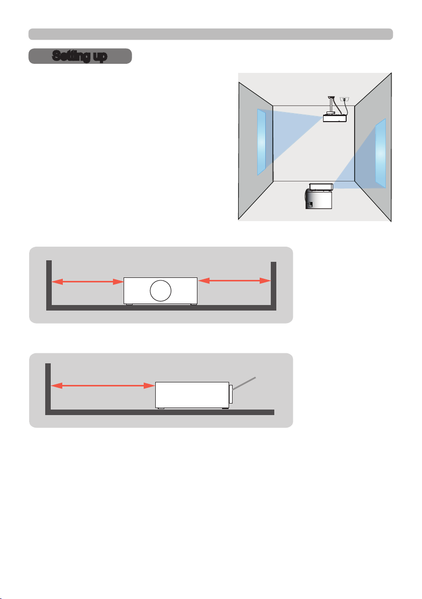
Setting up
Install the projector according to the
environment and manner the projector will be
used in.
For the case of installation in a special state
such as ceiling mount, the speci ed mounting
accessories and service may be required.
Before installing the projector, consult your
dealer about your installation.
When there are the obstacles on both sides of the projector.
30cm or greater 30cm or greater
When there are the obstacles behind the projector.
50cm or greater
(continued on next page)
8
Lens
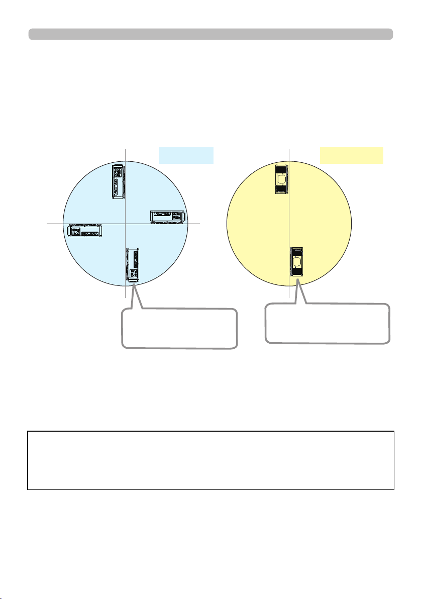
Setting up
Positioning Precautions
Although this projector can be installed in 360° range (including Portrait), life of
optical parts will be shorten in the following situation:
1. If the projector is installed with the lens facing downward.
2. If the projector is installed with the IO ports side facing upward at the Portrait
situation.
90°
180°
270°
Installing the projector with
the lens facing downward
is not recommended.
Tilt position
0°
Portrait position
Installing the projector with
the IO ports side facing
upward is not recommended.
Installing the lens unit
See the manual of the optional lens.
Note: The Dukane model described in this document is manufactured by
Hitachi and uses the same firmware, software programs, control code, and
accessory parts. The equivalent Dukane to Hitachi model is 9100WUSS
(LP-WU9100B).
9
Setting up
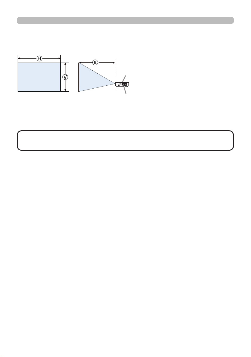
Arrangement
Refer to "Throw distance" in User’s Manual (booklet) for details.
Projector top
Projector bottom
Ⓗ×Ⓥ :
ⓐ :
Screen size
Projection distance (from the front of the projector unit)
NOTE • The installation position and the operating environment such as
temperature, altitude may affect the brightness of the display.
(continued on next page)
10

Arrangement (continued)
Setting up
WARNING
►Install the projector where you can access the power
outlet easily. If an abnormality should occur, unplug the projector urgently.
Otherwise it could cause a re or electric shock.
►Do not subject the projector to unstable conditions. If the projector falls
or topples over, it could result in injury or damage to the projector and the
surrounding things. Using a damaged projector could result in a re and an
electric shock.
• Do not place the projector in unstable places, such as an inclined surface,
places subject to vibration, on top of a wobbly table or cart, or a surface that is
smaller than the projector.
• Do not put the projector on its side, front or rear position.
• Do not attach nor place anything on the projector unless otherwise specied in
the manual.
• Do not use any mounting accessories except the accessories specied by the
manufacturer. Read and keep the manuals of the accessories used.
• For special installation such as ceiling mounting, be sure to consult your dealer
beforehand.
• It is possible to install the projector for any direction with specied mounting
accessories. Consult with your dealer about such a special installation.
• DLP chip(s) is/are precision-made parts. In rare cases, pixels may be missing
or lit, but this is not a malfunction.
• Direct high-power laser beam onto the lens surface can damage the DLP
chip(s).
• Remove all the attachments including the power cord and cables, from the
projector when carrying the projector.
►Do not install the pro
jector near thermally conductive or ammable
things. Such things when heated by the projector could result in a re and burns.
• Do not place the projector on a metal stand.
►Do not place the projector where any oils, such as cooking or machine
oil, are used. Oil may harm the product, resulting in malfunction, or falling from
the mounted position.
►Do not place the projector in a place where it may get wet. Getting the
projector wet or inserting liquid into the projector could cause a re and an
electric shock, and damage the projector.
• Do not place the projector near water, such as in a bathroom, kitchen, or
poolside.
• Do not place the projector outdoors or by the window.
• Do not place anything containing liquid near the projector.
►Do not block the ventilation inlet and ventilation outlet of the projector.
If the ventilation inlet and ventilation outlet of the projector are blocked, the
accumulated inside heat may cause re.
(continued on next page)
11

Setting up
Arrangement (continued)
CAUTION
►Place the projector in a cool place with sufcient
ventilation. The projector may shutdown automatically or may malfunction if its
internal temperature is too high.
Using a damaged projector could result in a re and an electric shock.
• Do not place the projector in direct sunlight or near hot objects such as heaters.
• Do not place the projector where the air from an air conditioner or similar unit
will blow on it directly.
• Do not place the projector on carpet, cushions or bedding.
• Do not stop up, block nor cover the projector's vent holes. Do not place
anything around the projector that could be sucked in or stuck to the projector's
ventilation inlet.
• Do not place the projector at places that are exposed to magnetic elds, doing
so can cause the cooling fans inside the projector to malfunction.
►Avoid placing the projector in smoky, humid or dusty place. Placing the
projector in such places could cause a re, an electric shock and malfunction of
the projector.
• Do not place the projector near humidiers. Especially for an ultrasonic
humidier, chlorine and minerals contained in tap water are atomized and could
be deposited in the projector causing image degradation or other problems.
• Do not place the projector in a smoking area, kitchen, passageway or by the
window.
NOTICE
• Position the projector to prevent light from directly hitting the
projector's remote sensor.
• Do not place the product in a place where radio interference may be caused.
• Set the ALTITUDE of the SERVICE item in the OPTION menu correctly. It is
recommended to leave it at AUTO usually (
60). If the projector is used with a
wrong setting, it may cause damage to the projector itself or the parts inside.
• Keep heat-sensitive things away from the projector. Otherwise, they may be
damaged by the heat from the projector.
NOTE
high rotation of the fan for cooling temporarily.
12
• When the temperature inside the projector rises high, it may cause the
Setting up
Connecting with your devices
Before connecting the projector to a device, consult the manual of the device to
conrm that the device is suitable for connecting with this projector and prepare
the required accessories, such as a cable in accord with the signal of the device.
Consult your dealer when the required accessory did not come with the product or
the accessory is damaged.
After making sure that the projector and the devices are turned off, perform
the connection, according to the following instructions. Refer to the gures in
subsequent pages.
WARNING
►Use only the appropriate accessories. Otherwise it could
cause a re or damage the projector and devices.
• Use only the accessories specied or recommended by the projector’s
manufacturer. It may be regulated under some standard.
• Neither disassemble nor modify the projector and the accessories.
• Do not use the damaged accessory. Be careful not to damage the accessories.
Route a cable so that it is neither stepped on nor pinched out.
CAUTION
►For a cable with a core at only one end, connect the end
with the core to the projector. That may be required by EMI regulations.
NOTE
• Do not turn on or off the projector while connected to a device in
operation, unless that is directed in the manual of the device. Otherwise it may
cause malfunction in the device or projector.
• The function of some input ports can be selected according to your usage
requirements.
• Be careful not to mistakenly connect a connector to a wrong port. Otherwise it
may cause malfunction in the device or projector.
- When connecting a connector to a port, make sure that the shape of the
connector ts the port.
- Tighten the screws to connect a connector equipped with screws to a port.
- Use the cables with straight plugs, not L-shaped ones, as the input ports of
the projector are recessed.
About Plug-and-Play capability
• Plug-and-Play is a system composed of a computer, its operating system
and peripheral equipment (i.e. display devices). This projector is VESA DDC
2B compatible. Plug-and-Play can be used by connecting this projector to a
computer that is VESA DDC (display data channel) compatible.
- Take advantage of this feature by connecting a computer cable to the
COMPUTER IN1 port (DDC 2B compatible). Plug-and-Play may not work
properly if any other type of connection is attempted.
- Use the standard drivers in your computer as this projector is a Plug-and-Play
monitor.
(continued on next page)
13
Setting up
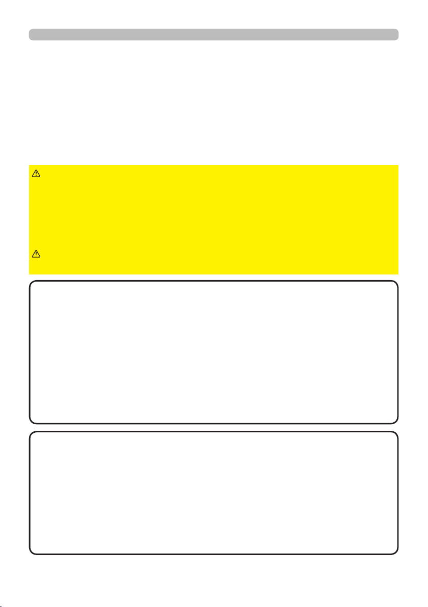
Connecting with your devices (continued)
Computer
TM
HDBaseT
12VOUTPUT
(OPTION)
REMOTE
CONTROL HDBaseT HDMI1 DVI-D HDMI2
NOTE
CONTROL V H
LAN
COMPUTERIN2
G/Y R/Cr/Pr COMPUTERIN1
B/Cb/Pb
• Before connecting the projector to a computer, consult the computer’s
DVI
IN OUT
SDI
manual and check the compatibility of the signal level, the synchronization
methods and the display resolution output to the projector.
- Some signal may need an adapter to input this projector.
- Some computers have multiple screen display modes that may include some
signals which are not supported by this projector.
- Although the projector can display signals with a resolution up to UXGA
(1600x1200) or up to W-UXGA (1920x1200), the signal will be converted
to the projector’s panel resolution before being displayed. The best display
performance will be achieved if the resolutions of the input signal and the
projector panel are identical.
• If you connect this projector and a notebook computer, you need output the
display to an external monitor, or output simultaneously to the internal display
and an external monitor. Consult the computer's manual for the setting.
• Depending on the input signal, the automatic adjustment function of this
projector may take some time and not function correctly.
(continued on next page)
14
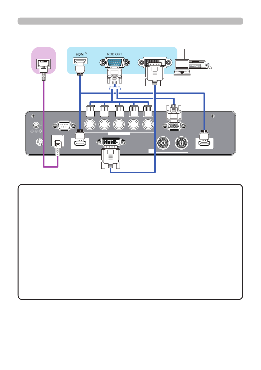
Connecting with your devices (continued)
Setting up
External
device
12VOUTPUT
CONTROL V H
(OPTION)
LAN
REMOTE
CONTROL HDBaseT HDMI1 DVI-D HDMI2
CAUTION
► Before connecting the projector to a network system be sure
Computer
G/Y R/Cr/Pr COMPUTERIN1
B/Cb/Pb
COMPUTERIN2
IN OUT
SDI
Access
point
to obtain the consent of the administrator of the network.
►
Do not connect the LAN port to any network that might have the excessive voltage.
About HDBaseT™ connection
• HDBaseT is a technology to transmit image, ethernet or serial control signal
via LAN cable.
• Use LAN cables of up to 100m long. Exceeding this length, the image will be
deteriorated, and even experience malfunction on LAN transmission.
- Quali ed cable is required for HDBaseT connection.
(continued on next page)
15
Setting up
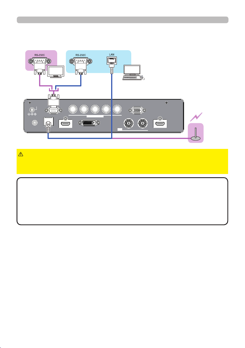
Connecting with your devices (continued)
VCR/DVD/
Blu-ray Disc
TM
player
12VOUTPUT
(OPTION)
REMOTE
CONTROL HDBaseT HDMI1 DVI-D HDMI2
NOTE
CONTROL V H
LAN
COMPUTERIN2
• The HDMI ports of this model are compatible with HDCP (High-band-
G/Y R/Cr/Pr COMPUTERIN1
B/Cb/Pb
IN OUT
SDI
width Digital Content Protection) and therefore capable of displaying video
signals from HDCP compatible DVD players or the like.
- The HDMI ports support the following signals:
For Video signals, refer to
User’s Manual (detailed) Technical
.
- This projector can be connected with another equipment that has HDMITM
connector, but with some equipment the projector may not work properly,
something like no video.
- Be sure to use an HDMITM cable that has the HDMITM logo.
- Use a Category 2-certi ed HDMITM cable to input 1080p@50/60 signal to the
projector.
• The HDMITM cables might come off easily due to the lack of a mechanical lock
on the cables and connectors.
・ The resolution of the signal input to the projector and signal output from the
projector may be restricted by the maximum resolution of the connected device
such as projector or monitor.
(continued on next page)
16
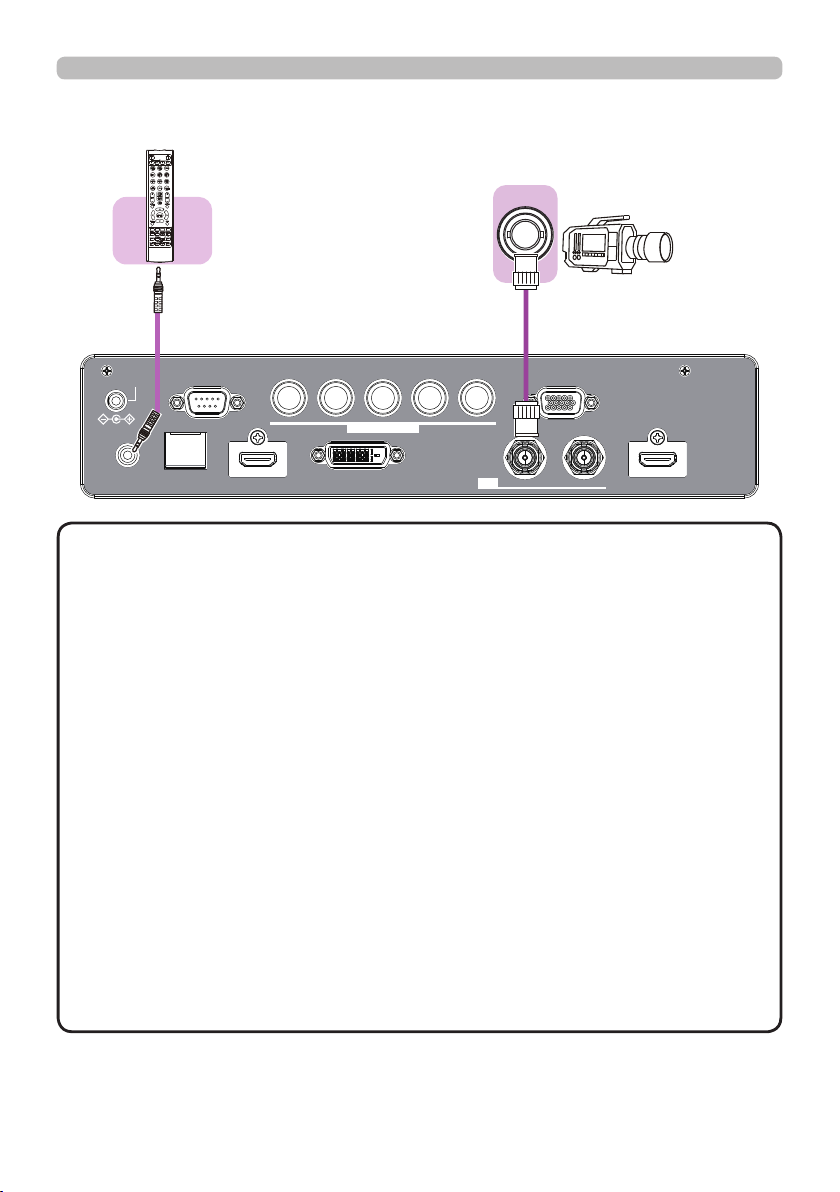
Connecting with your devices (continued)
(Wired)
Remote
control
INTERACTIVE
NETWORK
INFO
Setting up
SDI OUT
12VOUTPUT
(OPTION)
REMOTE
CONTROL HDBaseT HDMI1 DVI-D HDMI2
NOTE
CONTROL V H
LAN
COMPUTERIN2
G/Y R/Cr/Pr COMPUTERIN1
B/Cb/Pb
IN OUT
SDI
• To use a wired remote control, connect a wired remote control to
the REMOTE CONTROL port. This function is useful when a wireless remote
signal may not reliably reach the projector.
• The projector may not be operated correctly if they are operated from multiple
remote controls at the same time.
• The SDI port of this model supports the following SDI signals:
SD-SDI signal: conforming to SMPTE ST 259-C standard
YCBCR 4:2:2 10-bit
480i, 576i
Single link HD-SDI signal: conforming to SMPTE ST 292 standard
YPBPR 4:2:2 10-bit
720p@50/60, 1080i@50/60, 1080sf@25/30
3G-SDI Level-A signal: conforming to SMPTE ST 424 standard
YPBPR 4:2:2 10-bit
1080p@50/60
- This projector can be connected with another equipment that has SDI
connector, but with some equipments the projector may not work properly.
- Use a cable of 5CFB or greater (5CFB, 7CFB, etc.), or Belden 1694A or
greater to transmit the image properly. And use a cable with a length of 100m
or less.
- Setting by MENU is necessary depending on a connected device.
17
Setting up
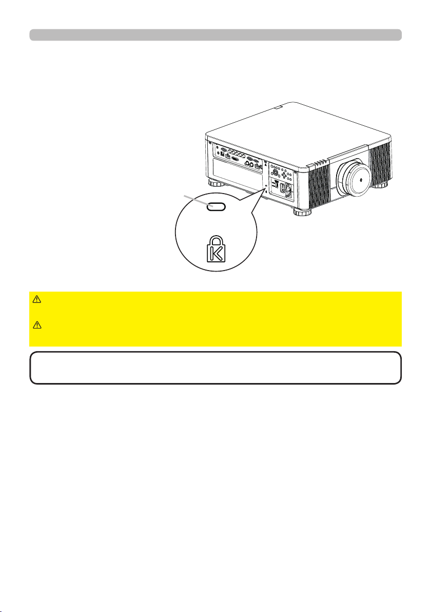
Using the security slot
This product has the security slot for the Kensington lock.
For details, see the manual of the security tool.
Security slot
WARNING
►Do not use the security slot to prevent the projector from
falling down, since it is not designed for it.
CAUTION
►Do not put a cable of the Kensington lock near a ventilation
outlet to prevent it from getting hot.
NOTE
• The security slot is not comprehensive theft prevention measures. It
is intended to be used as supplemental theft prevention measure.
18
Setting up
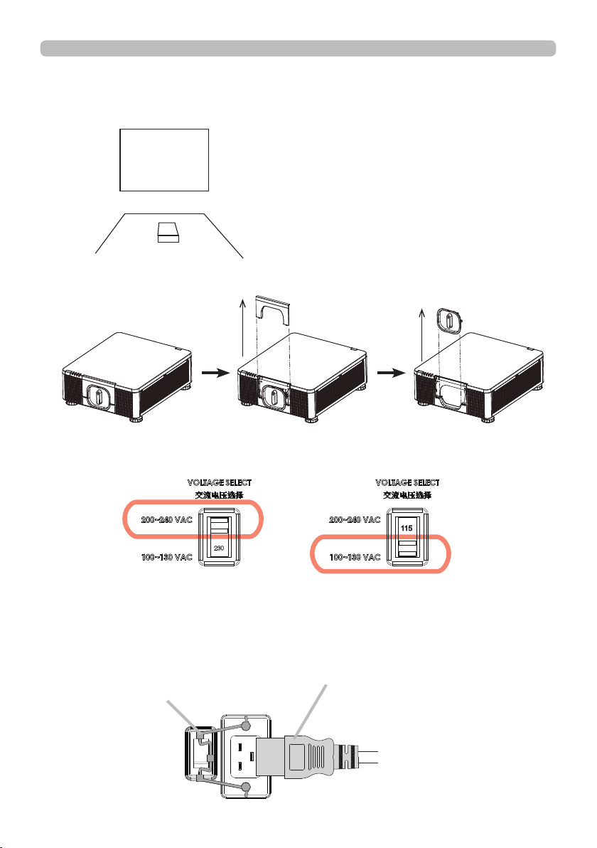
Installation of the projector
1. Installing the projector towards the screen
Screen
2. Removing the mount cap on the projector
3. Selecting the correct input voltage depending on your area
Select 200-240V
Select 100-130V
4. Connecting the power cord to the projector
Be sure that the power cord is not damaged and already connected to the power
outlet properly.
Secure the power plug by locking
the plug holder clamp.
Connect the female side of the
power cord to power input socket
of projector.
19
Setting up
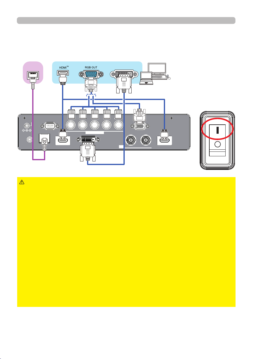
5. Connecting the projector to your PC and switching to “׀” to
turn on the power
POWER indicator turns to red, which means the projector is in standby mode.
TM
HDBaseT
12VOUTPUT
CONTROL V H
(OPTION)
LAN
REMOTE
CONTROL HDBaseT HDMI1 DVI-D HDMI2
WARNING
►Do not connect the projector to a power supply while no lens
B/Cb/Pb
COMPUTERIN2
DVI
G/Y R/Cr/Pr COMPUTERIN1
IN OUT
SDI
unit is attached to it.
►Use extra caution when connecting the power cord, as incorrect or faulty
connections may result in re and/or electrical shock.
• Do not touch the power cord with a wet hand.
• Only use the power cord that came with the projector. If it is damaged, consult
your dealer to get a new one. Never modify the power cord.
• Only plug the power cord into an outlet whose voltage is matched to the power
cord. The power outlet should be close to the projector and easily accessible.
Remove the power cord for complete separation.
• Do not distribute the power supply to multiple devices. Doing so may overload
the outlet and connectors, loosen the connection, or result in re, electric shock
or other accidents.
• Connect the ground terminal for the AC inlet of this unit to the ground terminal
of the building using an appropriate power cord (bundled).
NOTICE
• This product is also designed for IT power systems with a phase-to
phase voltage of 220 to 240 V.
20
Remote control
Remote control
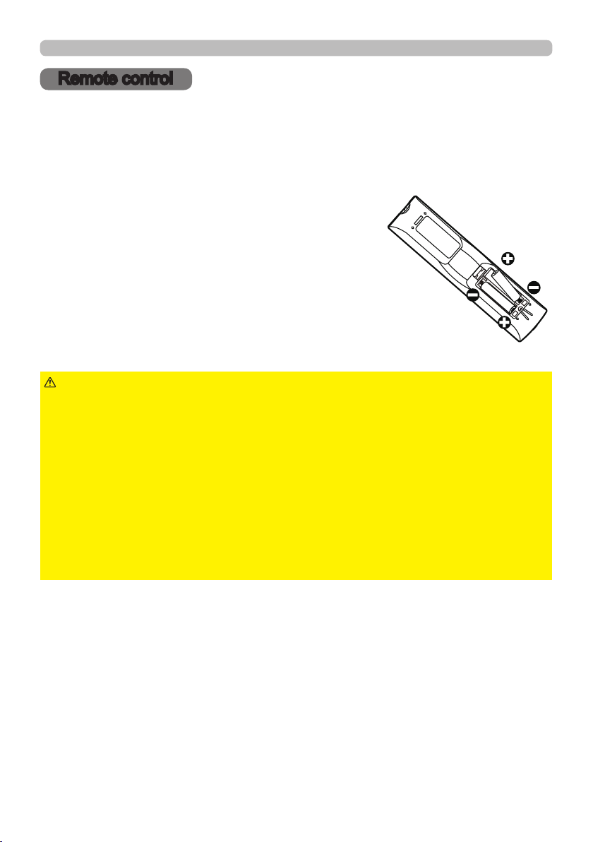
Installing the batteries
Insert the batteries into the remote control before using it. If the remote control
starts to malfunction, try to replace the batteries. If you will not use the remote
control for long period, remove the batteries from the remote control and store
them in a safe place.
Remove the battery cover.
1.
Align and insert the two AA batteries
2.
according to their plus and minus terminals
as indicated in the remote control. (Use
the appropriate AA carbon-zinc or alkaline
batteries (non-rechargeable) in accordance
with laws and regulations.)
Put the battery cover back to the former state.
3.
WARNING
directed. Improper use may result in battery explosion, cracking or leakage, which
could result in re, injury and/or pollution of the surrounding environment.
• Be sure to use only the batteries specied. Do not use batteries of different types at
the same time. Do not mix a new battery with used one.
• Make sure the plus and minus terminals are correctly aligned when loading a battery.
• Keep a battery away from children and pets.
• Do not recharge, short circuit, solder or disassemble a battery.
• Do not place a battery in a re or water. Keep batteries in a dark, cool and dry place.
• If you observe battery leakage, wipe out the leakage and then replace a battery.
If the leakage adheres to your body or clothes, rinse well with water immediately.
• Obey the local laws on disposing the battery.
►Always handle the batteries with care and use them only as
21
Remote control
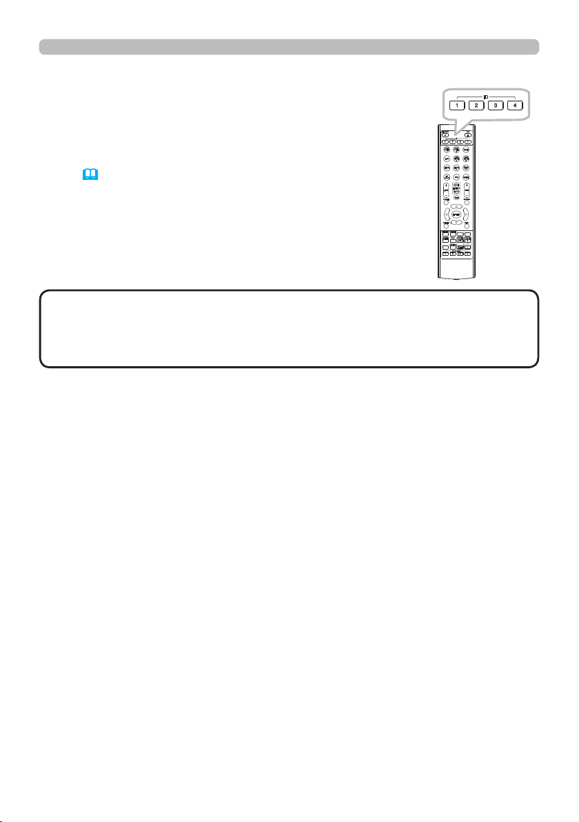
Using the REMOTE ID function
Use this function to control specic projectors by the remote
control assigned the same ID number when you use multiple
projectors of the same type at the same time.
Assign an ID number to each projector before using the
REMOTE ID item in the SERVICE menu of the OPTION
menu (61). Press the ID button with the same ID number
as assigned to the projector you are going to control. The ID
button selected will light for several seconds.
INTERACTIVE
NETWORK
INFO
NOTE
• Each time you press any button (except ID buttons), the ID button of
current selected ID number will light.
• To conrm the projector's current ID, press any ID button for three seconds.
Its number will be shown on each screen regardless of set ID of projector.
22
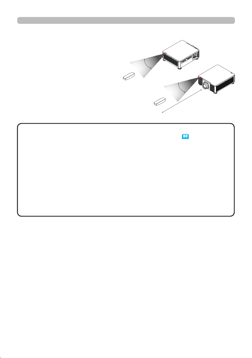
About the remote control signal
The remote control works with the
projector’s remote sensor. This
projector has two remote sensors
on the front and back sides.
The sensors can sense signals
within the following range:
30 degrees (15 degrees to the
left and right of the sensor) within
about 7 meters.
30°
Remote control
30°
m
7
(approx.)
NOTE
• You can deactivate one of the sensors using the INFRARED
REMOTE item in the SERVICE menu of the OPTION menu (61).
• The remote control signal reected in the screen or the like may be available.
If it is difcult to send the signal to the sensor directly, attempt to make the
signal reect.
• The remote control uses infrared light to send signals to the projector (Class 1
LED), so be sure to use the remote control in an area free from obstacles that
could block the remote control’s signal to the projector.
• The remote control may not work correctly if strong light (such as direct
sunlight) or light from an extremely close range (such as from an inverter
uorescent lamp) shines on the remote sensor of the projector. Adjust the
position of projector avoiding those lights.
23
Power on/off
Power on/off
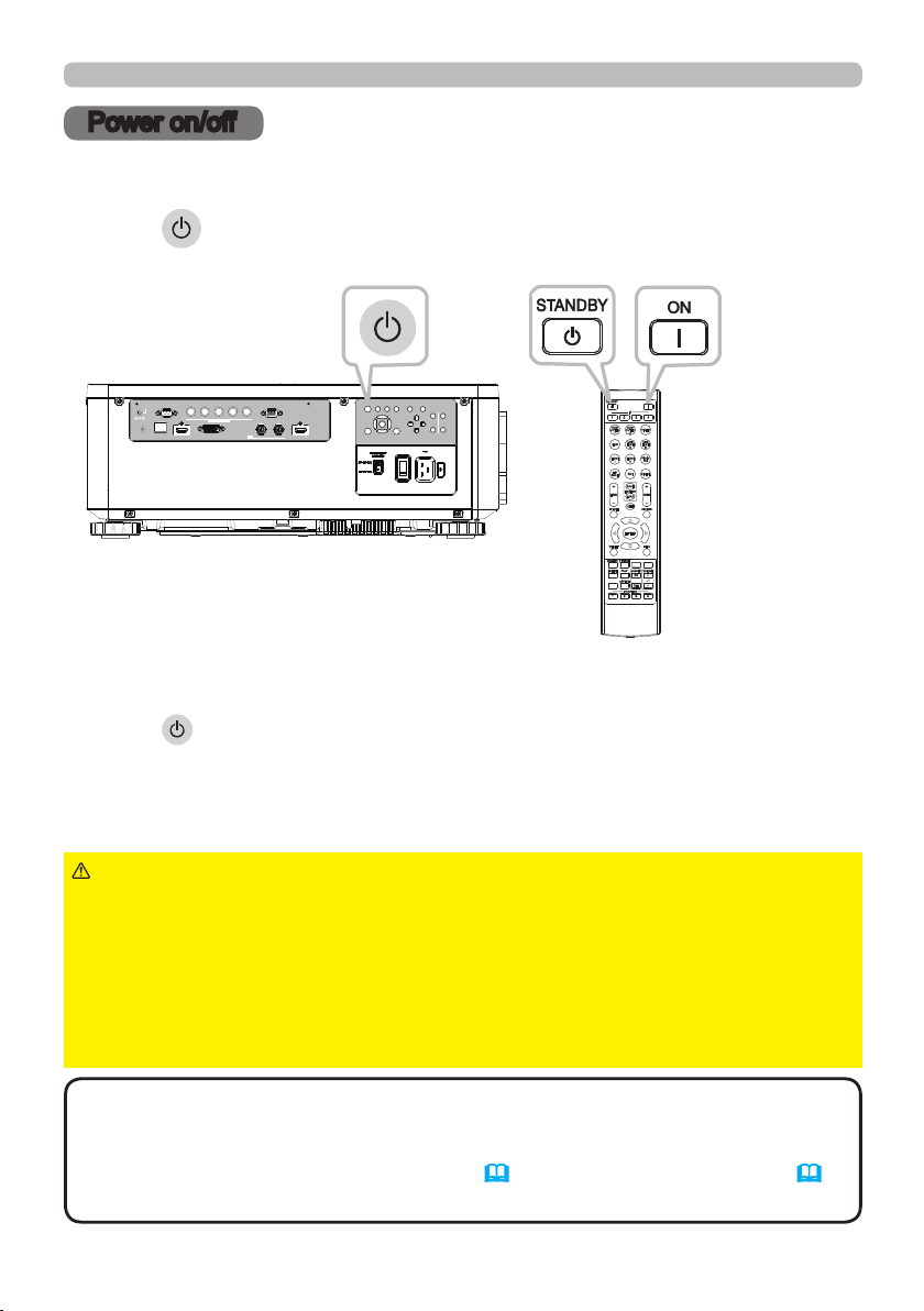
Turning on the power
Press the button on the projector or the ON button on the remote control to
start up the projector.
LENS
INPUT ASPECT BLANK
CONTROL V H
12VOUTPUT
(OPTION)
LAN
REMOTE
CONTROL HDBaseT HDMI 1 DVI-D HDMI 2
B/Cb/Pb
COMPUTER IN 2
G/Y R/Cr/Pr COMPUTER IN 1
IN OUT
SDI
AUTO
CENTERING
LENS
FOCUS ZOOM
EXITMENU
SHIFT
INTERACTIVE
NETWORK
INFO
Turning off the power
Press the button on the projector or the STANDBY button on the remote
control. The message will appear on the screen. Press the button again while the
message appears. When the projector has been turned off, the cooling fan will
remain in operation for approximately 120 seconds.
WARNING
►A strong light is emitted when the projector’s power is on.
Do not look into the lens of the projector or look inside of the projector through
any of the projector’s openings since the projection ray may cause a trouble on
your eyes.
►Keep any object away from concentrated projection light beam. Blocking the
beam by something causes high temperature and could result in re or smoke.
►Do not touch around the ventilation outlet during use or just after use, since it
is too hot.
NOTE
• Turn the power on/off in right order. Power on the projector prior to
the connected devices.
• This projector has the function that can make the projector automatically turn
on/off. Refer to the DIRECT POWER ON (58) and AUTO POWER OFF (58)
items of the OPTION menu.
24
Operating
Operating
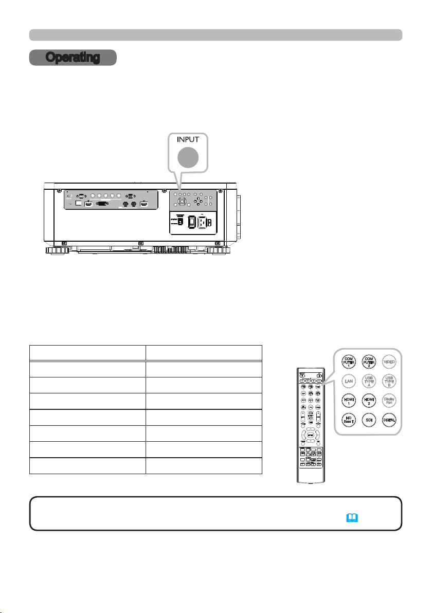
Selecting an input signal
Press the INPUT button on the projector. Select a desirable input referring to the
displayed input list. Even if you press the button for an input port which is not
supported, input source list is displayed like when pressing the INPUT button.
LENS
INPUT ASPECT BLANK
CONTROL V H
12VOUTPUT
(OPTION)
LAN
REMOTE
CONTROL HDBaseT HDMI 1 DVI-D HDMI 2
B/Cb/Pb
COMPUTER IN 2
G/Y R/Cr/Pr COMPUTER IN 1
IN OUT
SDI
Press HDMI 1, HDMI 2, COMPUTER 1, COMPUTER 2, HDBaseT, SDI or
DIGITAL button on the remote control.
The port corresponding to each button is selected as below.
AUTO
CENTERING
LENS
FOCUS ZOOM
EXITMENU
SHIFT
Button Ports
HDMI 1 HDMI 1
HDMI 2 HDMI 2
COMPUTER 1 COMPUTER IN1
COMPUTER 2 COMPUTER IN2
HDBaseT HDBaseT
INTERACTIVE
SDI SDI
NETWORK
INFO
DIGITAL DVI-D
NOTE
• While ON is selected for AUTO SEARCH item in OPTION menu, the
projector will keep checking the ports until an input signal is detected (58).
25
 Loading...