

Page 1
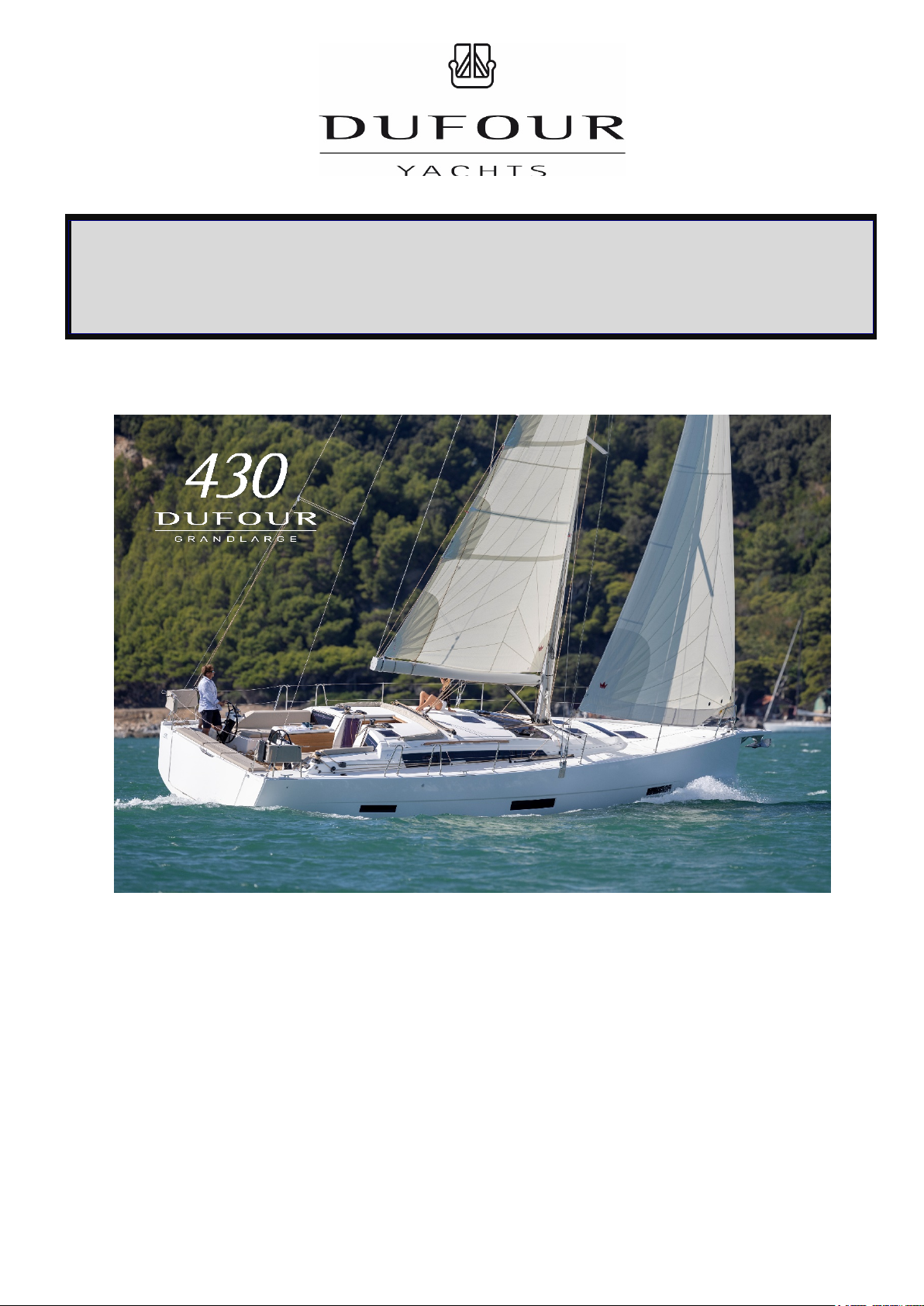
OWNER'S MANUAL
ENGLISH 26/02/2019 1/92 DUFOUR 430 Grand Large
YACHT DESIGN CATEGORY: A
COMPLIANT WITH EUROPEAN DIRECTIVE 2013-53-EU
Page 2

This page intentionally left blank.
This page intentionally left blank.
This page intentionally left blank.
ENGLISH 26/02/2019 2/92 DUFOUR 430 Grand Large
Page 3

Your agent:
Surname
Manual
I, the undersigned:
Name
Address
owner of DUFOUR 430 No.
confirm that I have received the DUFOUR 430 Owner's Manual and accept that it is written in the
Dated:
Signature:
Detach along dotted line
…………………………………………………………………………………………………………………
11, Rue Blaise Pascal- 17187 PERIGNY CEDEX- FRANCE
I, the undersigned:
Name
Address
owner of DUFOUR 430 no.
confirm that I have received the DUFOUR 430 Owner's Manual and accept that it is written in the
Dated:
Signature:
is the DUFOUR YACHTS representative and will give you all the help you need to solve any
difficulties you might have during the launching and masting of your boat, as well as for
commissioning and maintenance technical checks. If necessary, he will help you with the
administrative process of registering your boat.
As soon as you become the owner, familiarize yourself with the manual supplied with your boat,
sign and date the receipt acknowledgements below, and give (or send) the last one to your agent.
Acknowledgement of receipt of the Owner's Manual. Owner's copy to be kept in your
English language.
Owner's Manual receipt acknowledgement to be returned to DUFOUR YACHTS
English language.
ENGLISH 26/02/2019 3/92 DUFOUR 430 Grand Large
Page 4

This page intentionally left blank.
This page intentionally left blank.
This page intentionally left blank.
ENGLISH 26/02/2019 4/92 DUFOUR 430 Grand Large
Page 5

CONTENTS
INTRODUCTION ................................................................................................................................. 7
I. GENERAL INFORMATION ......................................................................................................... 8
Yacht design category _________________________________________________________ 8
Certification _________________________________________________________________ 8
Identification ________________________________________________________________ 8
Builder's plate _______________________________________________________________ 9
Degrees of danger ____________________________________________________________ 9
II. PRINCIPAL SPECIFICATIONS ................................................................................................. 10
These values are those of the deep-keel version with a standard mast. ........................................ 11
III. ELECTRICAL SYSTEMS .............................................................................................................. 12
Safety and operating instructions for the electrical system ____________________________ 12
Fitting new equipment ________________________________________________________ 12
Batteries __________________________________________________________________ 13
Electric windlass ____________________________________________________________ 13
Ins 220/110 Volt installation (ISO 13297: 2000) ___________________________________ 14
IV. GAS INSTALLATION ................................................................................................................... 15
General Information __________________________________________________________ 15
V. DRAIN & SANITATION SYSTEM ................................................................................................... 17
Characteristics of the drain system (ISO 15083: 2003) ________________________________ 17
Pressurized fresh-water pump _________________________________________________ 17
Seacocks __________________________________________________________________ 18
Operation of the sea toilets ____________________________________________________ 18
Holding tank operation (ISO 8099:2000) ___________________________________________ 18
VI. FLOODING .................................................................................................................................. 19
VII. FIRE PROTECTION .................................................................................................................... 19
Installation _________________________________________________________________ 19
Safety Instructions ___________________________________________________________ 20
VIII. ENGINE .................................................................................................................................... 21
General precautions __________________________________________________________ 21
Exhaust gas emission _________________________________________________________ 21
Safety 21
Wintering __________________________________________________________________ 22
IX. FUEL INSTALLATION ................................................................................................................. 22
X. HELM SYSTEM ............................................................................................................................ 22
Helm _____________________________________________________________________ 22
Emergency tiller _____________________________________________________________ 23
XI. SAILING ..................................................................................................................................... 24
XII. FALL PREVENTION AND MEANS OF GETTING BACK ABOARD................................................... 25
XIII. LIGHTNING PROTECTION ......................................................................................................... 26
Maintenance ________________________________________________________________ 26
Personal protection during thunderstorms ________________________________________ 26
XIV. ENVIRONMENTAL PROTECTION & SAFETY .............................................................................. 26
XV. SAFETY FACILITIES ................................................................................................................... 27
XVI. HANDLING, TRANSPORTING, HAUL-OUT ................................................................................. 27
XVII. MOORING, ANCHORING, AND TOWING .................................................................................. 288
Responsibility _______________________________________________________________ 28
XVIII. GUARANTEE, TRANSFER OF OWNERSHIP ............................................................................. 29
1. Presentation .......................................................................................................................... 34
ENGLISH 26/02/2019 5/92 DUFOUR 430 Grand Large
Page 6

2. Accommodation layout .......................................................................................................... 35
3. Deck fittings layout ............................................................................................................... 38
4. Sail plan ................................................................................................................................ 40
5. Running rigging, sheets and halyards layout ........................................................................ 42
6. 220V circuit diagram ............................................................................................................. 47
7. Charging and power system diagram .................................................................................... 49
8. 12V electric panel ................................................................................................................. 51
9. Electrical panel rear wiring .................................................................................................. 53
10. 12V electrical installation diagram ....................................................................................... 57
11 220V electrical installation diagram ..................................................................................... 60
12 Fuse location diagram ........................................................................................................... 63
13 Steering system diagram ...................................................................................................... 66
14 Gas system diagram .............................................................................................................. 68
15 Abandon ship plan ................................................................................................................. 71
16- Freshwater system diagram ................................................................................................. 74
17 Drain system diagram ........................................................................................................... 77
18 Skin fitting location diagram ................................................................................................. 79
19 Mechanical installation diagram ........................................................................................... 82
20 Gas system diagram .............................................................................................................. 84
21 Holding tank installation diagram ......................................................................................... 86
22 Lifting diagram ...................................................................................................................... 88
23 Navigation lights ................................................................................................................... 90
ENGLISH 26/02/2019 6/92 DUFOUR 430 Grand Large
Page 7

INTRODUCTION
DUFOUR YACHTS is pleased to present you with this manual, which will help you get to know your
boat better.
This Manual has been produced to help you use your boat safely and enjoyably. It contains details of the
boat, the equipment supplied or fitted, its systems and information about their use. Read it carefully and
familiarize yourself with the boat before using it.
This Owner’s Manual is not a course in sailing safety or seamanship. If this is your first boat or you are
changing to a type of boat you are unfamiliar with, for your convenience and safety, make sure you gain
experience in handling and using it before taking command. Your agent, national sailing or cruising
federation or yacht club will be happy to give you information about sailing schools or qualified instructors
in your area.
Ensure that forecast wind and sea conditions correspond to the design category of your boat, and that you
and your crew are capable of handling the boat in these conditions. Even when your boat is suitable for
them, the sea and wind conditions corresponding to design categories A, B, and C vary from severe storm
for category A to severe conditions for the top end of category C, subject to dangers of abnormal gusts or
waves; these are dangerous conditions in which only an experienced, trained crew in good shape, sailing a
properly-maintained boat, can sail in a satisfactory manner.
This Owner's Manual is not a detailed maintenance or repair guide. In the event of problems, consult the
boatbuilder or their representative. If a maintenance manual is provided, be sure to use it.
Always employ the services of an experienced professional for maintenance, fitting accessories, or
modifications. Modifications that could affect the characteristics of the boat must be assessed, performed
and documented by qualified personnel. The boatbuilder cannot be held responsible for modifications
made without their approval.
In certain countries, a skipper's license or some form of authorization is required, or special rules and
regulations are applicable.
Always maintain your boat correctly and make allowances for deterioration due to age or resulting, where
applicable, from heavy or unsuitable use. Any boat, however sturdy, can be severely damaged if it is used
incorrectly. This is incompatible with safe sailing. Always suit your speed and heading to the prevailing sea
conditions.
If your boat is equipped with a life raft, read its instruction manual carefully. The crew must have all the
safety equipment on board (life-jackets, harnesses, etc.), corresponding to the type of boat, weather
conditions, etc. In some countries, this equipment is mandatory. The crew must be familiar with the use of
all the safety equipment and the emergency safety procedures (man overboard recovery, towing, etc.);
training sessions are regularly organized by sailing schools and clubs.
It is recommended that all persons wear appropriate buoyancy aids (life-jackets, personal flotation devices)
when on deck. It should be noted that in certain countries, it is compulsory to wear a buoyancy aid
(complying with national regulations) at all times.
KEEP THIS MANUAL IN A SAFE PLACE AND PASS IT ON TO THE NEW OWNER IF YOU
SELL THE BOAT.
NOTICE: Our boats are regularly improved in light of our customers’ experiences and
research carried out by the shipyard. As a result, the specifications given in this Owner’s
Manual are not contractually binding and may be changed without notice and without any
obligation to update them. This manual is intended to cover as much information as
possible, so certain equipment or paragraphs might not apply to your boat. In case of
doubt, please refer to the inventory which should have been given to you by your agent
when you placed your order.
ENGLISH 26/02/2019 7/92 DUFOUR 430 Grand Large
Page 8
I. GENERAL INFORMATION
Significant wave
into account
Up to 0.5 m
inclusive
Yacht design category
Your DUFOUR 430 enters into design category OCEAN (category A).
Under normal conditions of use, your boat is designed to sail in waves of a significant height over 4
m, winds of Beaufort force 8 and above, and to resist under more severe conditions.
This navigational capacity also depends on the skill of the crew, their physical capacity, boat
maintenance and equipment.
So always take care before putting to sea.
DUFOUR YACHTS is not able to guarantee perfect functioning of the boat in exceptional sea
conditions (violent storms, hurricanes, cyclones, waterspouts, etc.)
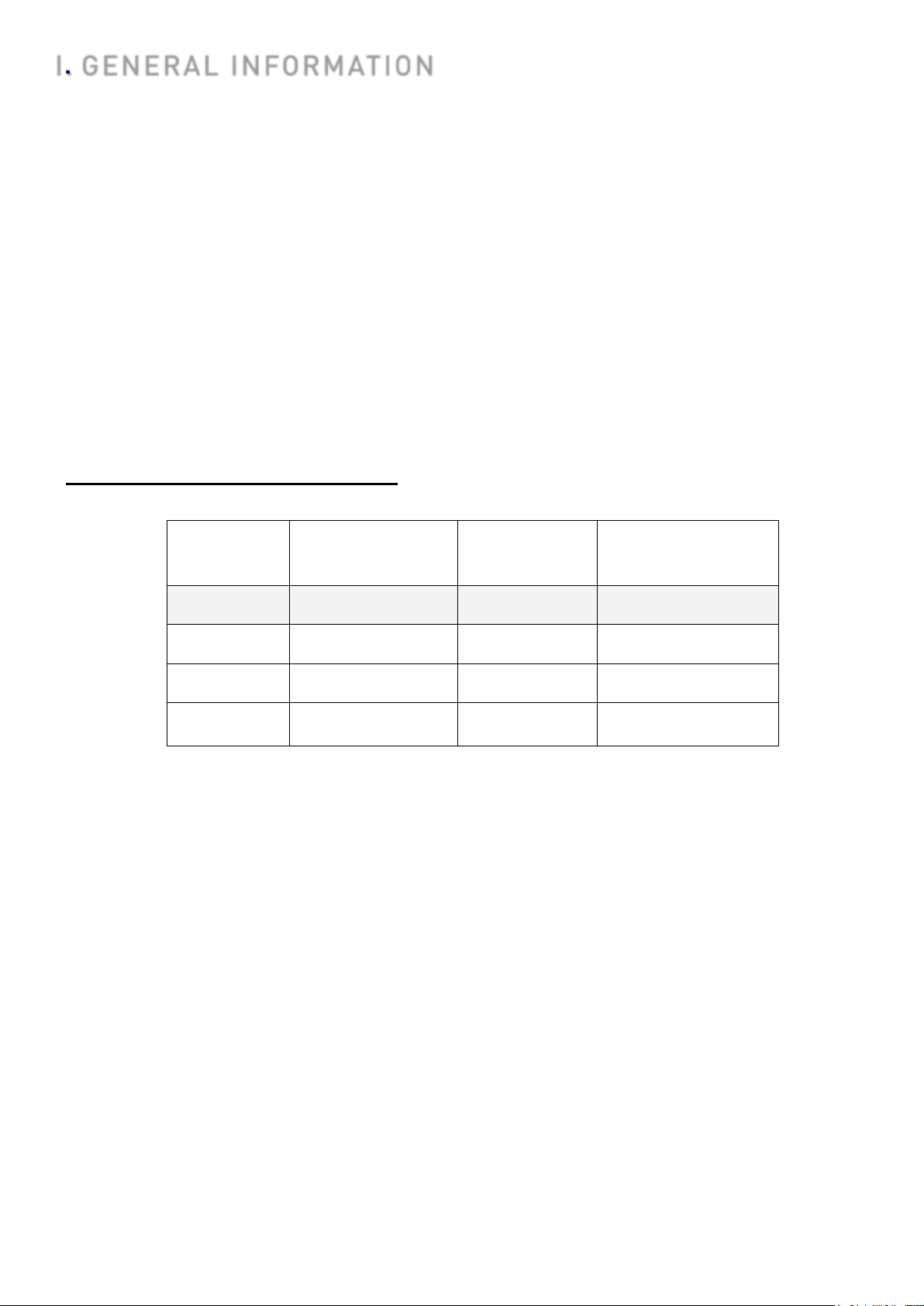
SUMMARY OF DESIGN CATEGORIES
Categories
Design
Wind strength
(Beaufort)
Wind
speed
height to be taken
A Above 8 Up to 28 m/s Above 4 m
B Up to 8 Up to 21m/s Up to 4 m inclusive
C Up to 6 Up to 17 m/s Up to 2 m inclusive
D Up to 4 Up to 13 m/s
Check the weather forecast before putting to sea: take to the sea, but don’t take any
risks!
In port: every day, the Harbour Master's Office posts weather bulletins and forecasts for the
next few days.
Météo France on 08 36 68 08 08
Navifax - direct on 08 36 70 18 52
VHF: CROSS transmits several bulletins per day, preceded by an announcement on
Channel 16.
Certification
DUFOUR YACHTS has chosen Institut pour la Certification et la Normalisation dans le Nautisme
(ICNN) as the notified body (0607) to check the conformity of the Dufour 430 series with European
Directive CE 2013-53-EU, under module B.
Identification
The hull identification number is located on the starboard side of the transom. It contains a series
of letters and numbers that begin with FR-DUF...
ENGLISH 26/02/2019 8/92 DUFOUR 430 Grand Large
Page 9
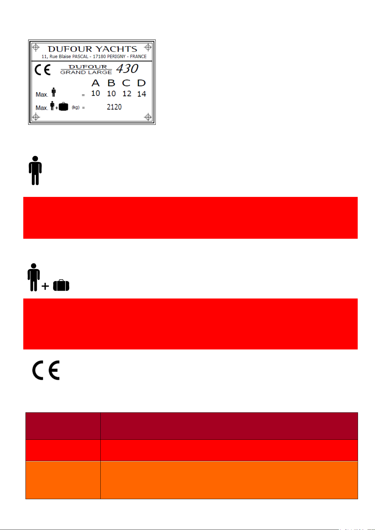
Builder's plate
Category A = 10
Category D = 14
: recommended by the builder when the boat sails
: CE marking indicating the compliance of the boat with all
: recommended by the manufacturer including the
weight of all passengers aboard, provisions and
included in the boat’s light displacement, but
excluding the contents of the tanks.
Some of this information is provided on the builder’s
plate attached to the boat. A full explanation of this
information is given below.
Yacht design category = A : (see 1.1)
Max. number of people:
Category B = 10
Category C = 12
WARNING
Do not exceed the maximum recommended number of people. However, many people there are
aboard, the total weight of the people and equipment must never exceed the maximum
recommended load.
Max recommended load:
Category A = 2120 kg
Category B = 2120 kg
Category C = 2120 kg
Category D = 2120 kg
WARNING
When loading the boat, never exceed the recommended maximum load. Always load the boat
carefully and distribute the weight in a suitable manner in order to maintain the theoretical trim
(approximately horizontal). Avoid placing heavy loads in the upper parts.
under sea conditions that correspond to its design
category.
personal belongings, in addition to all equipment not
the provisions of the Directive. (See also: Written
Declaration of Compliance).
Degrees of danger
DANGER
WARNING
CAUTION
ENGLISH 26/02/2019 9/92 DUFOUR 430 Grand Large
Indicates an extreme intrinsic risk that presents a high probability of
death or permanent injury if proper precautions are not taken.
Indicates a risk that presents a high probability of death or permanent
injury if proper precautions are not taken.
Indicates a reminder about safety-related practices, or points out
dangerous practices that could result in personal injury or damage to
the boat or its components, or to the environment.
Page 10
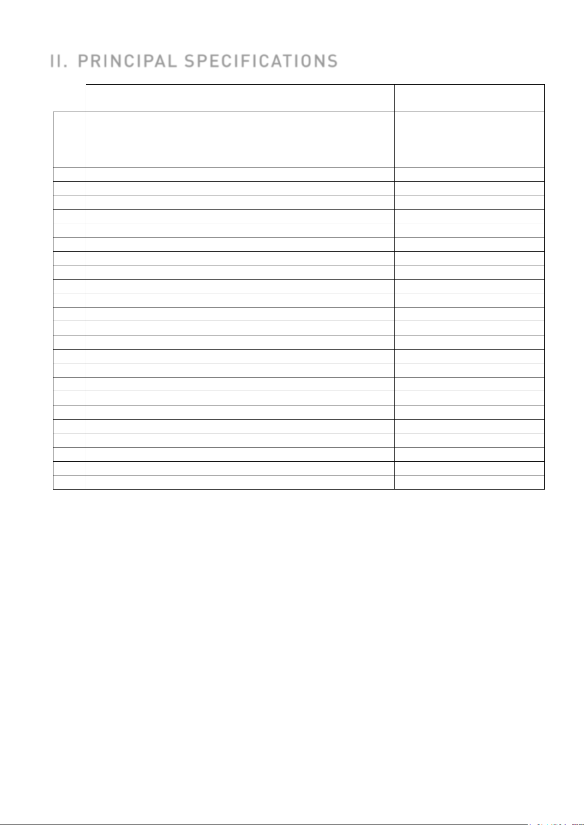
Model:
DUFOUR 430
Grand Large
Constructor
Dufour Yachts
17180 Périgny - FRANCE
Architecture:
Umberto FELCI
Interior design
DUFOUR Design
Yacht design category
A No. of the notified body
CE/0607
CIN No.
FR-DUFHXXX1XXXX
Primary means of propulsion
Sail
L
max
Length overall * (with bowsprit)
13.24 m
LH
Hull length*
12.50 m
B
max
Maximum beam*
4.30 m
BH
Hull beam*
4.30 m
HA
Maximum air draft*
19.20 m
T
max
Unladen draft (Deep keel) *
2.10 m
Deep keel weight
2600 kg
Unladen draft (Shallow keel) *
1.75 m
Shallow keel weight
2700 kg
Standard mainsail area (approx.)
46 m²
Jib area (approx.)
29 m²
Genoa area (approx.)
38 m²
Maximum permissible on-board engine power
60 CV / 44 kW
Water capacity excl. 40 L (approx.) water heater
430 L
Diesel capacity (approx.)
250 L
Holding tank / total volume
95 L
Engine battery
105 Ah
Auxiliary battery (excluding options)
315 Ah
II. PRINCIPAL SPECIFICATIONS
11, Rue Blaise Pascal
* The above specifications comply with ISO 8866, i.e.:
L
: maximum length of the boat including normally fixed parts such as bow rollers, pulpits, etc.
max
LH: maximum length of the vessel including structural elements that are an integral part of the
vessel, and excluding removable parts.
B
: breadth of the vessel measured between the outermost portions and may include
max
detachable parts such as top rails, railings, etc.
B
: breadth of the vessel measured between the outermost fixed portions and excluding all
H
removable parts
H
vertical distance between the unladen water line and the highest point of the mast structure.
A:
(this does not take into account equipment such as lights and antennas that may be attached to
the masthead)
T
: the maximum draft is measured at the lowest point of the boat’s keel
max
N.B.: due to the trim and load of the boat, it is not usually possible to use all the various
tank capacities for fresh water and diesel. It is recommended that you maintain a diesel
reserve of 20%.
ENGLISH 26/02/2019 10/92 DUFOUR 430 Grand Large
Page 11
Weights and displacements
A B C D
MLC
9982
10008
10082
10108
MMO
10246
10272
10346
10372
mL
2718
2718
2718
2718
M
LDC
12700
12726
12800
12826
mLA
11702
11728
11802
11828
Loaded arrival
(MLA)
STIX (deep
keel)
37.99
AVS (deep
keel)
114.2 °
Values expressed in kg
A = deep keel + standard mast version - B = deep keel + furling mast version
C = shallow keel + standard mast version - D = shallow keel + furling mast version
MLC: Boat's weight specification for light displacement
M
m
builder's plate) and 95% of the total weight of the various liquids (drinkable or not) contained in the
tanks.
M
m
tanks or tanks holding fuel, oil and drinking water and minus 90% of the edible provisions, but
including the combination of optional items of equipment or deck fittings least favourable for
stability.
The total weight of liquids includes the black water tanks: the scenario taken into account is the
most restrictive with three items of equipment.
Boat's weight specification for minimum conditions of use
MO:
maximum load used for the stability study, including the maximum recommended load (see
L:
Boat's weight specification for maximum load conditions
LDC:
Weight specification for the boat in maximum load conditions minus 85% of the stationary
LA:
Specific information
This vessel has been assessed with the help of the Stability Index (STIX), a measure of overall
safety with regard to stability, which takes into account the effects of the length of the vessel, its
displacement, hull proportions, stability characteristics and its resistance to flooding.
The second index (AVS, angle of vanishing stability) represents the heel angle at which stability is
lost, in degrees.
Minimum operating
condition (MMO)
41.61
120.0°
These values are those of the deep-keel version with a standard mast.
condition
ENGLISH 26/02/2019 11/92 DUFOUR 430 Grand Large
Page 12

III. ELECTRICAL SYSTEMS
Check the condition of the batteries (charge and electrolyte level) and the charging system
Carry spare bulbs for all navigation lights and interior lighting. Respect power ratings,
Install or replace the devices or electrical equipment by elements that exceed the prescribed
the electrical installation is under voltage, except for an
Safety and operating instructions for the electrical system
WARNING
Improper use of the DC and/or AC systems may give rise to fire or explosion hazards.
Improper use of the DC and/or AC systems may give rise to fire or explosion hazards.
Always:
●
before putting to sea.
● Disconnect and remove batteries for wintering.
● Do not let battery voltage drop below 10.5 V during wintering.
●
particularly for navigation lights.
● Check the operation of navigational instruments.
● Check the operation of navigation lights before sailing at night.
Never:
● Work on an electrical installation under voltage.
● Modify an installation and the relevant layouts, except by a qualified naval electrician.
● Change or modify the circuit breaker capacity of protection devices.
●
capacity without recalibrating conductors and protection devices.
● Leave the boat unattended when
automatic bilge pump and protection circuits against fire or theft.
If a fuse or circuit-breaker trips repeatedly, you should consult a specialist to determine the cause
of the short-circuit.
Fitting new equipment
Since 1 January 1996, electrical equipment is subject to the European Directive on
''electromagnetic compatibility'' (Ref 89/336/EEC). It is therefore necessary that any new
equipment you may wish to install meets the requirements of this standard and bears the CE mark.
Equipment must also be supplied with a compliance certificate and instructions for use.
In the case of 220 or 110 V installations, use only double-insulated or earthed equipment. Respect
the instructions for installation when installing these devices (wire gauge, protection).
To avoid maintenance problems, note any modifications to the electrical layout in the manual.
ENGLISH 26/02/2019 12/92 DUFOUR 430 Grand Large
Page 13

Batteries
The standard battery installation consists of two 105 Ah auxiliary batteries and one 105 Ah engine
battery. With the electric winch option, there are three 92 Ah AGM batteries. For a windlass and
bow thruster, add one or two 92 Ah AGM batteries at the front.
Their capacities have been designed to handle the power requirements of the on-board
accessories. To avoid any problems, it is necessary to keep a close eye on the maintenance and
correct charging of the batteries.
CAUTION!
● When you install new electrical devices, make sure that the overall consumption of these
devices remains proportional to the capacity of your batteries.
● Always disconnect the negative (-) battery terminal before the positive (+) terminal.
● Never allow a conductive object (tools, etc.) to bridge across the two battery terminals.
● When handling batteries, avoid any leakage of electrolyte liquid by keeping them horizontal.
Wear gloves and proper clothing to avoid any risk of contact with the electrolyte in the event of a
leak.
● In the event of a projection of electrolyte, thoroughly rinse the part of the body concerned and
consult a doctor.
Electric windlass
CAUTION!
When you use the electric windlass, it is essential to run your engine with a slight acceleration.
ENGLISH 26/02/2019 13/92 DUFOUR 430 Grand Large
Page 14

220/110 Volt installation (ISO 13297: 2000)
extremity of a ship/shore supply cable dangle into the water. It may create an
DANGER!
The on-board 220V installation is protected by a circuit breaker and fitted with a residual current
device. The wiring of additional 220V on-board accessories must be carried out by professionals
and the master circuit-breaker uprated if necessary.
- Do not modify the electrical installation of the boat or the relevant layout. Installation, modification
and maintenance should be carried out by a qualified naval electrician. Have the system checked
every 2 years
- Disconnect the boat power supply when the system is not in use.
- Connect the metallic housing of on-board electrical devices to the boat’s protection conductor
(green conductor or green with a yellow stripe).
- Use double-insulated or earthed electrical appliances.
- A test of the differential circuit breaker (RCD) should be carried out every month if possible.
CAUTION!
When the boat is moored at the quayside, set the isolator to the open position.
DANGER!
Your boat is not supplied with a shore/boat supply cable or a male plug for the shore outlet. The
cable must be suitable for outdoor use. Its diameter should be adapted to its length and the
power of the main circuit breaker (See the electrical diagram). The plug must be suitable for the
shore socket (if necessary, seek professional advice). It should be as close as possible to the IP
67/IEC529 type
WARNING: To reduce the risk of electric shock and fire.
● Switch off the shore supply at the on-board isolator before connecting or disconnecting the
shore/boat supply cable.
● Connect the shore/boat supply cable to the boat before connecting it to the shore outlet.
● Disconnect the shore/boat supply cable at the shore outlet before disconnecting it from the
boat.
● Properly close the protection of the power supply inlet when docked
Never:
● Make any modifications to the shore supply cable: use only compatible connectors.
● Swim near a boat connected to a shore supply socket: risk of electrocution!
Location of the 220 V master circuit-breaker: aft starboard cabin.
Have the system checked at least every 2 years.
During haul-out maintenance, set to the closed position in order to have earth [grounding]
protection via the shore socket.
WARNING
Never let the
electrical field that could injure or kill nearby swimmers.
ENGLISH 26/02/2019 14/92 DUFOUR 430 Grand Large
Page 15

WARNING
flame appliances use up the oxygen in the cabin and release combustion
Proper ventilation is necessary: open both the deck hatch or porthole
ak before it has been inspected and repaired by a competent
IV. GAS INSTALLATION
General Information
- Pressure for use: 30 mbar (see indication on the label in the gas locker and on the regulator valve)
- Vents to use for the evacuation of burnt gas: hatch above the cooker and companionway
- Do not obstruct quick access to the elements of the gas installation (cylinder locker, shut-off valve).
- Regularly inspect the hoses at least once a year and change them if damaged, if the expiry date is
exceeded, or five years after the manufacture date printed on the hose.
- Valves attached to empty cylinders must be closed and disconnected. Protective covers, caps and
plugs must be kept in place. Reserve cylinders must be kept in housings or lockers for LPG
cylinders with ventilation to the exterior, or stored at the exterior of the boat, protected from
weather and mechanical damage, and in such a way that any leaking gas can only escape to the
exterior of the boat.
- Lockers for LPG cylinders must not be used for the storage of any other equipment.
- Ensure that the gas cylinder and regulator comply with the requirements of the cooker (flow rate,
pressure, type of gas) and with the regulations in force in the country where it is being used.
- Make sure that all valves are closed when replacing gas cylinders.
Operation of the LPG system
- The valves of the supply lines and cylinders must be closed when the devices are not used or
before filling, and must be immediately shut off in case of emergency.
- The valves of the appliances must be closed before opening the cylinder valve.
Fuel-burning nakedproducts inside the vessel.
located nearby and the companionway when the appliances are in operation.
- The cooker is suspended and can therefore be used when under sail. However, limit its use when
large angles of roll or heel are likely.
Checking the system
- The LPG system should be checked for leaks before each use as follows:
- Close the valve of the appliance, open the LPG cylinder valve, allow the pressure of the pressure
gauge to stabilise, close the valve of the LPG cylinder, check the pressure indicated by the
pressure gauge located near the cylinder for three minutes. The pressure indicated by the pressure
gauge should be constant if there is no leak in the system.
- Information: the pressure gauge does not give an indication of the quantity of liquid LPG remaining
in the cylinder but only its vapour pressure, which is a constant at a given temperature.
- If a leak of LPG is detected or suspected, immediately take the following steps:
- Cut of the supply at the main supply valve(s).
- Extinguish any naked flames and other sources of combustion (heating appliances, cooking
appliances, lights, etc.)
- Do not operate any electrical switches.
- Evacuate the area, if possible.
WARNING
● Do not use an installation with a le
person.
ENGLISH 26/02/2019 15/92 DUFOUR 430 Grand Large
Page 16

WARNING
Close the
valve on the empty cylinder before disconnecting it to change. Properly ventilate the cylinder
out by a competent person. Have the system inspected at regular intervals or at intervals fixed by
DANGER!
Never use a naked flame to look for leaks.
- N.B.: The tests above do not replace the recommended periodic inspection by a professional.
Safety warnings
Never leave the boat unattended when naked flames are in use
Refrain from smoking or using a naked flame while LPG cylinders are being changed.
compartment when replacing cylinders.
Do not use the cooker/oven as a heating appliance.
If a leak is detected, close the main LPG supply and do not use LPG appliances.
smell of gas.
national requirements.
CAUTION!
Certain precautions must be taken to avoid any contact with naked flames or other hot areas.
Do not use solutions containing ammonia during manual tests for leaks
Detection system
The boat must be equipped with a fire alarm system (smoke detector, heat detector, etc.).
The recommended location is indicated on the evacuation plan (15).
This detector emits an audible signal in the case of an alert.
It has an independent battery that must be replaced when it indicates a loss of power, in
compliance with the manufacturer’s instructions or those indicated on the device.
It is essential to carry out a routine test at each boarding or every week in the case of prolonged
presence on board.
If the test shows that the device is faulty, it should be replaced by an equivalent device.
ENGLISH 26/02/2019 16/92 DUFOUR 430 Grand Large
Page 17

V. DRAIN & SANITATION SYSTEM
Pump type
Theoretical flow
rate
Manual
38 L @ 45
strokes/minute
12 V electric
2,000 L/h
isolating the forepeak and afterpeak are fitted with valves, these
Characteristics of the drain system (ISO 15083: 2003)
Read the operating and maintenance instructions for your boat’s bilge pump carefully.
WARNING
The bilge pump system is not designed to handle water entering as a result of holing of the hull.
It is intended to remove water coming from spray, leaks from seacocks or other moderate
leaks.
CAUTION!
● The level of water in the bilges must be kept to a minimum
● Make sure that bilge pumps are in working order before putting to sea.
● Regularly clean the bilge and pump suction points or strainers to keep them free of any debris
that could obstruct them.
If the watertight bulkheads
should be kept closed and only opened to drain water in the main bilge.
● Know where to find each hand pump and its handle.
● Locate the switch for the electric bilge pump on the electrical panel.
Fresh water is supplied to the sink and washbasins by an electric pump. A filter is installed
upstream of the pump, and must be cleaned regularly.
Never allow the pump to run if the tank is empty. Refill the tank before using the water
supply again.
The tanks can be sterilized using Clonazone® tablets (available from pharmacies). Every year,
remove the inspection covers and clean them by filling with water containing a bactericidal
detergent; leave it to act for a few hours, then rinse two or three times. During wintering, completely
fill the tanks to avoid the development of algae or bacteria. If there is a risk of freezing, empty the
tanks; never use anti-freeze.
Hot water is produced by a water-heater connected to the engine cooling circuit and the shore
electric supply.
After the water-heater has been emptied, make sure that the element is covered before power is
re-applied.
ENGLISH 26/02/2019 17/92 DUFOUR 430 Grand Large
Page 18
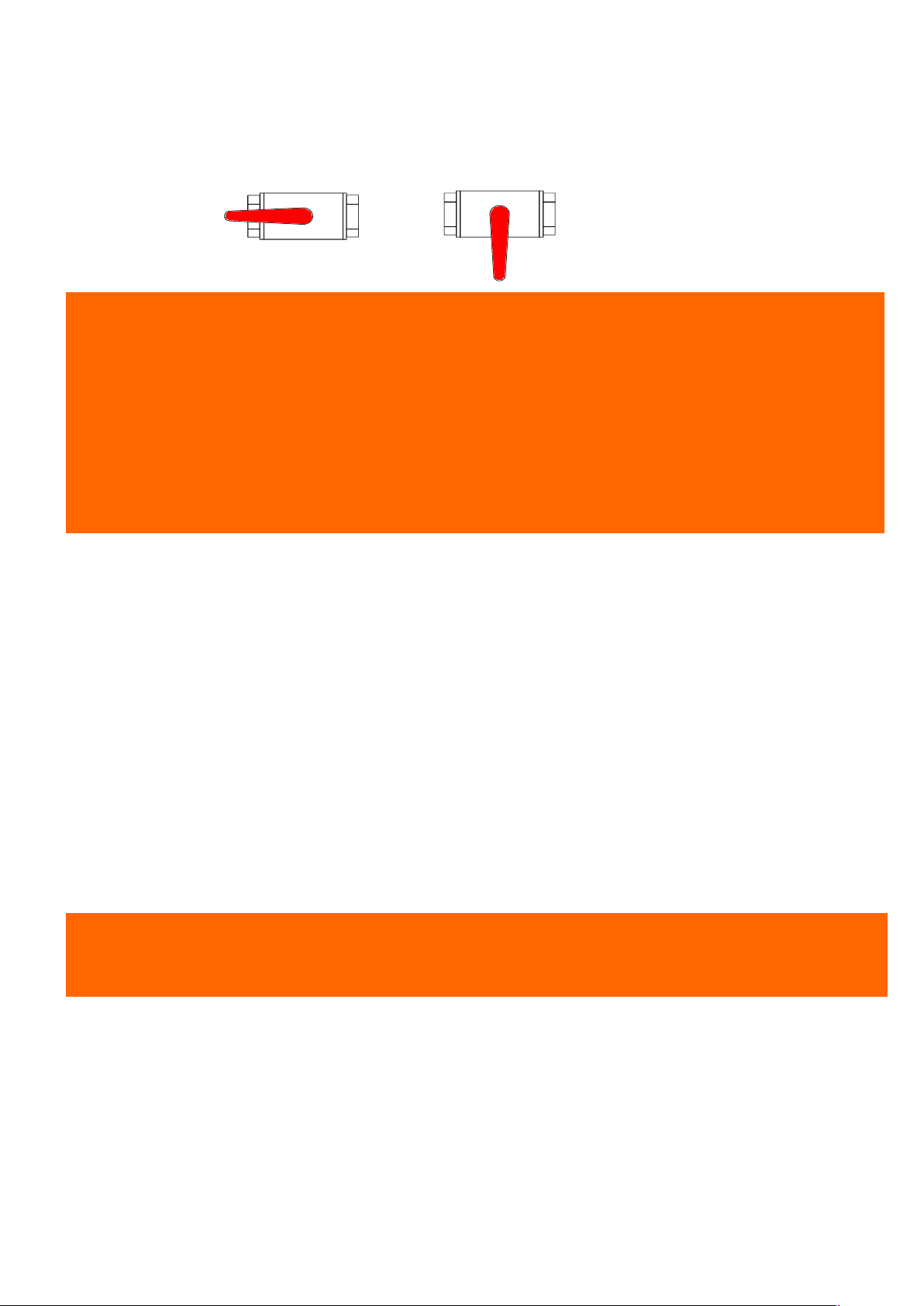
Seacocks are of the ¼-turn type:
Never interfere with the tightening of the seacocks to the hull. In the event of a leak, consult a
Keep the seacocks closed when not in use and remember to manipulate them regularly to
During wintering, clean and rinse the seacocks and skin fittings. Inspect brass fittings; slight
Where a holding tank is fitted, take care to lock the discharge valve, to avoid any accidental
Vanne ouverte
Vanne fermée
- OPEN position: handle in the direction of the seacock body,
- CLOSED position: handle perpendicular to the seacock body.
CAUTION!
●
professional.
● In bad weather or when leaving your boat, close all the sanitation system seacocks.
●
maintain their flexibility of use. An unused seacock can eventually seize up.
●
surface corrosion is normal.
● In the event of more serious corrosion, consult your agent.
- Open the sea water inlet cock.
- Open the bowl emptying seacock.
- Set the lever to the “FLUSH” position.
- Operate the pump.
- To empty the bowl and avoid any water slopping when heeling, set the lever to the “DRY BOWL”
position.
- Operate the pump until the bowl is dry.
- Repeat these flushing/emptying operations as many times as is necessary to ensure complete
emptying of the pipes.
When toilets are not being used, set the lever to the "DRY BOWL" position, or the "CLEF" position
for certain models.
- Close seacocks after use, as the toilet is below the waterline.
- Change the toilet seals regularly.
CAUTION!
discharge during wintering.
- Black water tanks operate with the manual toilet pump.
- The contents of the toilet pan are discharged straight into the holding tank.
- Periodically check that the vent is working properly.
- A deck plate is provided for emptying the tank.
- The discharge valve can be sealed in the closed position using a padlock.
- Once a season, arrange to clean out the tank using a biodegradable disinfectant chemical. Use a
biodegradable deodorant product without formaldehyde to limit odours.
Leave the system empty if the vessel is to be left in below-freezing temperatures. During winter lay-
up, use a food-grade, non-toxic antifreeze that complies with local regulations.
ENGLISH 26/02/2019 18/92 DUFOUR 430 Grand Large
Page 19
VI. FLOODING
To avoid the risk of flooding the boat:
- Check that portholes, deck hatches, and any other openings that may cause flooding, are closed
before putting to sea.
- While under way, close all seacocks when they are not in use, except for the engine water intake.
- Do not exceed the maximum recommended loading.
- The level of water in the bilges must be kept to a minimum.
- Avoid adding weight in high places so as not to affect the stability.
Periodically check:
- Skin fittings, seacocks and pipes are watertight.
- Proper emptying of the cockpit drains.
- Stern glands or sail-drive seals for watertightness.
WARNING
Cockpit locker covers must be fastened shut before putting to sea. This is particularly
important for lockers with a serious risk of flooding
VII. FIRE PROTECTION
Installation
Since fire extinguishers are subject to national regulations, they are not supplied with the boat.
However, when in use, this boat must be fitted with portable extinguishers with the following
capacities, installed in the following locations (see drawing in appendix):
- No. 1 - cockpit locker, within reach of the helmsman - capacity 1 kg - 5A34B
- No. 2 - saloon banquette (fore) - extinction capacity 1 kg - 5A34B
If you decide to install a carbon dioxide (CO2) extinguisher, be aware that it may only be fitted in
accommodation areas that contain powered electrical equipment (e.g. electric motors, battery
compartments, electrical panels) or flammable liquids (e.g. galley).
Only compatible replacement parts must be used in the fire protection system. They must bear the
same markings and be technically equivalent.
In addition, a fire blanket must be stowed in the aft starboard cabin (in the L-galley version) or near
the cooker, which can be very useful in the case of a cooker fire caused by oil.
Similarly, for safety on deck, a fire bucket equipped with a lanyard must be stored in an
immediately accessible locker.
If non-combustible materials are stored in the engine compartment, they must be secured to avoid
the risk of falling onto the machinery and must not obstruct access to the engine compartment or
its exit.
ENGLISH 26/02/2019 19/92 DUFOUR 430 Grand Large
Page 20

WARNING
use only on electrical or cooker fires. To avoid
Do not open the engine compartment immediately after putting out a fire to avoid the release of
fighting equipment checked in accordance with the stipulations of the builder and the
shers of equal
r are
the boat’s installations (especially
If a CO2 extinguisher is fitted, the following information must be displayed close to its location:
“This extinguisher contains CO2 suffocation after discharging, leave the area immediately. Ventilate before entering.”
toxic smoke or spraying of burning materials (oil, water)."
CAUTION!
It is the responsibility of the owner/skipper to:
● Have fireregulations in your country.
● Replace fire-fighting equipment if it has expired or been discharged, with extingui
or greater capacity.
● Show members of the crew:
- The location and operation of fire-fighting equipment.
- the location of the engine compartment discharge hole
● Ensure that fire-fighting equipment is readily accessible whenever the boat is occupied.
● Always keep the bilge clean and check that there is no fuel or gas vapour and no fuel leak.
● Indicate escape routes.
You must never:
● Obstruct passageways to the emergency exits (deck hatches).
● Obstruct safety controls (gas valves, fuel valves, electrical switches).
● Obstruct fire extinguisher stowages.
● Leave the boat unattended with a cooker or heater on.
● Use a gas lamp in the boat.
● Fill a fuel tank or change a gas cylinder while the engine is running, or the cooker or heate
on.
● Smoke while handling fuel or gas.
● Place free-hanging curtains near the cooker or any other appliance which has an open flame.
● Store flammable substances in the engine compartment.
●Modify, or allow any non-qualified person to modify, any of
electrical, fuel, or gas).
ENGLISH 26/02/2019 20/92 DUFOUR 430 Grand Large
Page 21

VIII. ENGINE
CAUTION!
capacities of the boat and be performed by an engineer
After the first launching and tensioning of rigging, check the alignment of the propeller shaft or the
Make sure that the water intake seacock for the cooling system is open, and that water is
ment containing petrol (outboard motor, tank, petrol generator, etc.) in
.
exhaust gases
In order to avoid all risk of serious injury from the propeller, the engine must not be started when
engine must be stopped for any engine maintenance or checking
operations. Otherwise, special attention must be paid to moving parts (propeller shafts, belts,
Regular maintenance must be carried out in compliance with the engine manufacturer’s
recommendations. Read the engine operating instructions that come with the boat carefully. Do not
hesitate to consult your agent or a qualified professional. In particular, follow the instructions for
wintering.
General precautions
Do not use the sail and engine if the heel angle is more than 10°.
Any engine change must respect the
specializing in marine mechanics.
sail-drive flange ring.
● Ensure that the ventilation openings (vents, engine air intake grating) are clear.
●
indeed coming out of the engine exhaust.
● Prevent any deterioration to the fuel supply circuits.
● Do not store equip
compartments not designed for this purpose.
Put the throttle in neutral before starting the engine to keep the boat from moving and/or the
propeller from turning.
On subsequent launches, a brief check of propeller fixing can be made. Incorrect operation of the
folding propeller will lead to vibration.
Regularly check the condition of the anodes and ensure that they are suitable for the boat's
environment (fresh water, salt water). Change the anodes every year. The anodes have an
average life of 1–2 years.
These anodes are made of zinc. You must not use magnesium ones. Impressed current cathodic
protection systems should be avoided.
If the anodes are not eroded, you need to check:
- that they have not been painted over,
- that they are correctly attached and in contact with the hull,
- and that they are indeed made of zinc.
Exhaust gas emission
DANGER!
Internal combustion engines produce carbon monoxide. Prolonged exposure to
can have serious consequences, and may even cause death.
Safety
DANGER!
there are people swimming near the boat.
Whenever possible, the
etc.) in order to avoid any risk of injury.
ENGLISH 26/02/2019 21/92 DUFOUR 430 Grand Large
Page 22
Wintering
the trim and loading of your boat, not all of the nominal fuel capacity may be
Read the operating and maintenance instructions for the engine that goes with your boat and the
instructions for wintering carefully.
In the absence of other instructions, proceed as follows:
- Close the engine water intake seacock,
- Disconnect the hose from the engine water intake seacock,
- Drain the sea-water circuit,
- Place the pipe into a drum of –25° anti-freeze coolant,
- Run the engine until the fluid comes out of the exhaust,
- At the end of this operation, re-connect the pipe to the seacock,
- Attach a notice to the electrical panel and the battery isolator stating that the engine water intake
seacock is closed.
IX. FUEL INSTALLATION
In the event of deterioration, flexible fuel pipes must be replaced by pipes bearing the same
markings. Do the same for all fuel lines.
CAUTION!
● Depending on
used. Always maintain a 20% reserve for safety.
● Avoid contact between flammable materials and hot parts of the engine.
● Clean up any overflow of fuel that may occur when filling the tanks.
You must never:
● Store flammable materials in unventilated spaces.
● Smoke while filling tanks.
● Obstruct ventilation openings (vents, engine air intake grating): make sure they are clear.
● Modify the installation except by a qualified technician.
X. HELM SYSTEM
The steering system plays a vital role in the safety and comfort of your boat.
Helm
The DUFOUR 430 is fitted with a dual wheel with a system of rudder cables and chains as well as
with an emergency tiller.
Checks to be carried out periodically: check the play in the various elements (rudder
stock/bearings, tension and wear in mechanical components) and grease the sprocket and chain if
necessary.
Your system is designed with 6mm stainless steel cable, twisted 7x19. These cables may be
replaced due to wear and fatigue.
The frequency of the change depends on the type of use and the tension and maintenance
conditions that might affect their lifespan.
ENGLISH 26/02/2019 22/92 DUFOUR 430 Grand Large
Page 23

is fitted with an emergency tiller which must be kept readily accessible; we
Careful examination will reveal any damaged cables. A cloth soaked in machine oil may be used to
wipe along the entire length of the cables.
If you find a broken twist, this means that the cable has reached the end of its lifespan and that you
will need to change it.
The same type of cable (material and diameter) must strictly be used to avoid any risk of breakage
or premature fatigue.
In the event of any doubt or problem, consult your agent.
Emergency tiller
CAUTION!
● The Dufour 430
advise stowing it in one of the nacelle cockpit lockers.
● It is designed only for sailing at reduced speed in the event of damage to the helm.
To use it:
- Unscrew the deck-plate to reveal the head of the rudder stock.
- Fit the tiller onto the head of the rudder stock.
ENGLISH 26/02/2019 23/92 DUFOUR 430 Grand Large
Page 24
XI. SAILING
In all situations, adapt the speed of your boat to the surrounding conditions and always maintain a
Make sure that you always have sufficient distance to stop or manoeuvre if necessary to avoid a
Out of courtesy and for the safety of other vessels, make sure not to create a significant wake
WARNING
the deck. Please refer to
point for the
specification
for light displacement, the standard equipment on board and the manufacturer's catalogue
board weight distribution (e.g., the addition of a radar, engine replacement,
Towing another boat produces significant extra loading, which will have an adverse effect on the
Lift heavy weights using the boom.
WARNING
safety margin. Pay particular attention to:
● Sea conditions, currents and the strength of the wind
● Movement of other boats
● Port manoeuvres
● When passing through mooring areas
● Obey the rules of right of way as set out in the COLREGs
●
collision
● Respect speed limits
●
near other craft.
● Movable items must be carefully secured when at sea
● You must fit your boat with grab lines. Anchor-points are provided on
the deck fittings plan for your boat. These grab lines are used as an anchorharnesses for moving towards the front of the boat.
● The stability of your boat has been designed taking into account the boat's weight
options.
Any alteration to onetc.) can affect the stability, trim and performance of your boat.
Breaking waves represent a significant threat to stability.
stability of your boat.
● You must never:
Field of vision
The skipper’s vision from the steering position may be obstructed by one or more of the following
variable conditions:
- Loading and distribution of the load
- Speed
- Sea conditions
- Reduced visibility (due to rain, darkness and fog)
- Reduced visibility (due to changing and raising the sails)
- Lights inside the boat
- Position of awnings or covers
- Moving people or equipment located within the helmsman’s field of vision.
Pay attention when you are moving from one helm position to another.
CAUTION!
Some large size forward sails (Genoa, code 0, spinnakers, etc.) may obstruct vision for a long
time. Keep an active watch while they are in use.
ENGLISH 26/02/2019 24/92 DUFOUR 430 Grand Large
Page 25
XII. FALL PREVENTION AND MEANS OF GETTING BACK ABOARD
While underway, it is recommended to move about on deck only in areas provided for this
purpose. These areas (side decks, cockpit, coach roof, lateral seats, etc.) are provided with nonskid coverings or teak (optional) to make it safe to move about.
On the DUFOUR 430, the entire working deck inside the guard lines and bulwarks can be used
safely. Passageways have been provided, when necessary, on glass surfaces and are marked by
anti-slip zones.
Note that the aft platform, when open, is not considered as a secure area. Moreover, it must be
kept closed when sailing.
Depending on sea conditions, wind and the degree of heel, it is also recommended that you use
the harness by attaching it to the various attachment points mentioned in the deck fittings plan.
When sailing, use whenever possible the various handholds provided by the helm grab rails,
cockpit table, lateral grab rails on the coach roof, shrouds, etc.
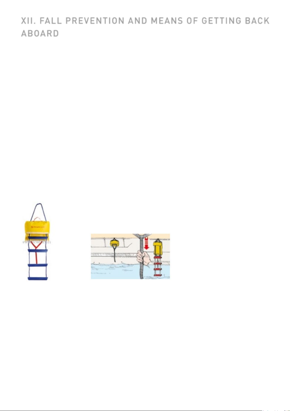
The DUFOUR 430 is equipped with a telescoping emergency ladder fixed to the aft gate. To use it,
lower the aft gate by releasing the hoisting line and then unfold the ladder and pivot it into the
correct position.
A safety ladder is also provided in case of emergency. When the boat is in use, it must be located
on the port or starboard pushpit and must be accessible from the water. Be sure to familiarize
yourself with this system, so that it is operational in any circumstances, including when under sail.
ENGLISH 26/02/2019 25/92 DUFOUR 430 Grand Large
Page 26

XIII. LIGHTNING PROTECTION
Most cleaning products, engine oils and fuels are likely to impact the environment, so they
artment, as these
Certain products can also pose a risk to your safety and that of others, which is why it is
Your boat is protected against lightning. The rigging is electrically earthed (grounded).
Nonetheless, for your safety, it is necessary to respect certain precautions.
Maintenance
If the vessel is struck by lightning:
- the protection equipment must be inspected for material damage and the condition
of the system, including the continuity of the earthing, must be checked.
- compasses, electrical and electronic equipment must be inspected to determine if
damage or compass calibration changes have occurred.
Personal protection during thunderstorms
WARNING
During a thunderstorm, it is recommended that you comply with the following instructions:
● People should stay below as much as possible.
● People should stay out of the water and not let their arms or legs hang into the water.
● While ensuring the satisfactory control of the boat and navigation, passengers must not touch
any element connected to a lightning protection installation, especially not in such a way as to
create a bridge between these elements.
● People should avoid touching any metallic parts of the rigging, spars, deck fittings and guardlines.
XIV. ENVIRONMENTAL PROTECTION & SAFETY
We recommend that you find out about local regulations concerning the environment and obey
international regulations against pollution in the marine environment (MARPOL), together with the
codes of good practice.
Do not discharge the toilets or the contents of the holding tanks near coasts or in prohibited areas;
use port or marina pumping systems for emptying the holding tanks before leaving port.
CAUTION!
●
should be discharged in authorized locations (check with the Harbour Master’s office).
● Do not run the bilge pump when oil or fuel is present in the engine comp
chemicals must be discharged in authorized locations.
●
important to read and follow the instructions for use.
● Chemicals must be labelled and stored in an appropriate place on the boat.
ENGLISH 26/02/2019 26/92 DUFOUR 430 Grand Large
Page 27
XV. SAFETY FACILITIES
There is no harmonization of mandatory safety equipment across the European Community. You
should find out about current national requirements for CE-marked vessels.
In France, the skipper is responsible for ensuring that recreational craft bearing the CE mark carry
the mandatory handling and safety equipment stipulated for the relevant sailing category.
Your boat is equipped with a life raft locker in the transom – direct access after opening the aft
gate. Carefully read the life raft instructions manual. The entire crew must be familiar with the use
of all safety equipment (harnesses, flares, life raft, etc.). Sailing schools and clubs regularly
organise training sessions.
XVI. HANDLING, TRANSPORTING, HAUL-OUT
When craning, take care that the slings are correctly positioned and are not fouling the propeller,
the sail-drive or a fragile transducer.
Lifting frames must be wide enough, or fitted with spreaders, so as to avoid applying excessive
lateral pressure on the rubbing strakes.
Avoid allowing slings to foul the life-lines. During transport or haul-out, the keel should be in proper
contact with its support and should be taking most of the boat’s weight.
Cradle pads must be positioned against structural elements in order to exert only the pressure
necessary for the boat to be properly balanced.
Take advantage of haul-outs to inspect the propeller, rudder, skin fittings and sensors.
CAUTION!
The aft lifting point is located near the propeller.
ENGLISH 26/02/2019 27/92 DUFOUR 430 Grand Large
Page 28

XVII. MOORING, ANCHORING, AND TOWING
eed the hull speed of a displacement
● The tow line should always be made fast in such a way that it can be released when under
Be sure to regularly inspect the various anchoring points of the boat. Replace any that show signs
of deterioration.
CAUTION! (ISO 15084:2003)
.
● The anchor points for anchoring and/or towing are the 2 fore cleats, which have a breaking
strain of approximately 6000 kg. Rear and mid-ship cleats can also be used for mooring. They
have a breaking strain of approximately 6000 kg.
● The breaking strain of the lines/chains should in general not exceed 80% of the breaking strain
of the anchor points, i.e. in this case a galvanized chain of 10 mm max. and a polypropylene line
of 18 mm max.
● Always tow or be towed at reduced speed. Never exc
boat in tow.
load.
It is the owner/operator’s responsibility to ensure that the mooring lines, towing cables, anchor
chains and lines, together with the anchors, are suitable for the boat’s intended use, i.e. that the
lines or chains do not exceed 80% of the breaking strain of the corresponding anchor point.
Moreover, the owner must take into consideration all necessary actions when attaching a tow line
to the boat.
ENGLISH 26/02/2019 28/92 DUFOUR 430 Grand Large
Page 29

XVIII. GUARANTEE, TRANSFER OF OWNERSHIP
A) CONTRACTUAL GUARANTEES
Note: This guarantee does not apply to boats being used
for commercial purposes (it being specified that any
hiring or chartering activity falls into this category) nor to
sailing boats taking part in competitions, which may be
covered by special guarantees.
8 - Guarantees
a) New boats and equipment:
8.1.1 – For both Commercial Purchasers and private
consumers domiciled outside the territory of the
European Union, the Seller grants the statutory
warranties as defined in the context of the sale of
vessels by Articles 1641 and 1648 of the French Civil
Code and in the context of a marine construction
contract by Articles 7 and 8 of Law no. 67.5 dated 3rd
January 1967 pertaining to vessels.
8.1.2 – For Purchasers domiciled within the territory of
the European Union and taking out the contract as
private consumers, the Seller is required to furnish the
guarantees as defined in the context of a boat sales
contract by Articles 7 and 8 of the Act dated 07/01/1967
pertaining to vessels, and in the context of the Order
(2005-136) dated 17/02/2005 and incorporated into the
French Consumer Code. Independently of this
guarantee, the Seller remains liable for discrepancies
between the goods and the contract and for redhibitory
defects under the conditions provided for under Articles
1641 to 1649 of the French Civil Code (see. 8.1.1).
8.2 – Visible defects: acceptance by the Purchaser
releases the Seller from their obligation in respect of
discrepancies and visible defects.
8.3 - Contractual guarantee:
Except for guarantee or penalty clauses expressly
agreed at the time of accepting the order, the Seller’s
guarantee is granted under the following conditions:
The Purchaser benefits from a contractual
guarantee running for two years from the date of
acceptance of the vessel, as noted on the
acceptance report.
This is limited to the replacement or free repair, at
the yacht-builder’s discretion, of any parts
acknowledged as being defective by the yachtbuilder’s technical services; this being without any
other compensation of any kind.
For components and accessories visibly bearing the
mark of another supplier, the guarantee is limited to
the guarantee offered by that supplier.
It is stipulated that any handling, transport, parking,
or convoying costs incurred in carrying out these
operations remain the sole liability of the buyer/user,
unless DUFOUR YACHTS yacht-builders offer to
waive them in full or in part.
The boat-builder’s warranty excludes:
- the cost of transporting the boat or any parts,
and any consequences thereof, together with
expenses and/or any damage arising out of the
inability to use the boat and/or the equipment;
- normal wear and tear;
- cracking, crazing, or discolouration of the
gelcoat;
- damage resulting from:
o fortuitous events or cases of force
majeure;
o conversions and modifications, or
repairs, even partial, carried out other
than in workshops authorized by the
maker;
o failure to observe the maintenance
recommendations set out in the Owner's
Manual supplied with the boat;
o improper use, in particular through
negligence, carelessness, abuse, or
abnormal usage;
o participating in competitions;
o failure to take necessary protective
measures;
o unsuitable storage or transport
conditions.
In order to benefit from the yacht-builder’s contractual
guarantee, each time they make a claim under it, the
buyer/user will be required to submit the boat delivery
certificate and the guarantee document, duly completed,
and, on pain of rendering it void, must notify their
dealer/vendor of the fault or defect in writing, in detail
and with justifications, within 15 days of its being
discovered.
8.4 – the guarantee covers usage at sea in wind and sea
conditions acceptable for safety and in accordance with
the vessel’s approval category. Under these conditions,
it cannot under any circumstances cover events arising
during or resulting from collisions, groundings, breaking
seas, tidal waves, cyclones, severe storms, and all other
exceptional events and/or events arising out of an error
of seamanship.
8.5 – Loss of or damage to products occurring after
handover do not release the Purchaser from their
obligation to pay the price.
b) Second-hand boats and equipment:
The order form specifies if the boat or equipment is
second-hand. The Purchaser benefits from a contractual
guarantee, covering hull and engine only, running for
one year from the date of acceptance of the vessel or
goods, as noted on the acceptance report.
ENGLISH 26/02/2019 29/92 DUFOUR 430 Grand Large
Page 30

c) In addition to the contractual guarantee detailed
above, the Seller remains liable for discrepancies in the
goods and for latent defects under the conditions
provided for under Articles 1641 to 1649 of the French
Civil Code and the provisions of the Order dated
17/02/2005, where applicable.
B) COMMON GUARANTEE CONDITIONS
Any claim under these guarantee conditions must be
made formally to DUFOUR YACHTS in writing as soon as
the defect is discovered, and within eight (8) days for
claims under the contractual guarantee. Any claim will
also be required to quote the serial number of the boat
concerned, and where applicable the part number(s) of
the part(s) involved in the guarantee claim.
Furthermore, the request must indicate the exact
circumstances under which the problem occurred.
In order to investigate the request, DUFOUR YACHTS
may ask for any details and appoint, at its own expense,
a surveyor or technician of its choice to determine the
circumstances of the occurrence of the problem and
demand any necessary papers.
Immobilization following problems encountered and/or
replacement and/or repair work, whatever the duration,
does not create entitlement to compensation.
The owner shall under all circumstances remain liable
for parking fees, customs dues and other ancillary
expenses.
All repairs and/or replacements will be carried out by an
authorized DUFOUR YACHTS agent or by a professional
duly acting under the Boatbuilder’s instructions. If the
nature of the repairs requires the guarantee repair work
to be carried out in DUFOUR YACHTS workshops or in
any location other than the place where the Product is
located, the owner will be liable for the cost of both
outward and return transport to the Yacht builder.
In the event that the boat needs to be taken out of the
water, haul-out and re-launching costs will be at the
owner’s expense.
C) TRANSFER OF GUARANTEES
The guarantees are afforded to the first purchaser of the
boat involved. They are only transferable with DUFOUR
YACHTS’ prior written agreement.
An ownership transfer note is supplied with the Product
documents. This must be sent to DUFOUR YACHTS
within thirty (30) days of the transfer.
D) STATUTORY DECLARATIONS
Article L.211-4 of the Consumer Code:
“The seller is obliged to deliver goods that are compliant
with the contract and is liable for any defects of
compliance on delivery.
He shall likewise be liable for discrepancies arising out
of the packaging, assembly instructions, or installation
when he is liable for this under the contract or it has
been carried out under his responsibility.”
Article L. 211-5 of the Consumer Code:
“In order to conform to the contract, the goods must:
1) Be suitable for the normal expected use for similar
types of goods and, where applicable:
- correspond to the description given by the seller and
possess the qualities the latter has presented to the
buyer in the form of a sample or model;
- present the qualities that a buyer may reasonably
expect with regard to public declarations made by the
seller, by the producer or by his representative,
particularly in advertising material or labelling;
2) Either present the characteristics defined by joint
agreement between the parties, or be suitable for any
special usage sought by the buyer that the seller has
been made aware of and has agreed to.”
Article L.211-12 of the Consumer Code:
“Actions arising out of a discrepancy lapse after two
years from the date the goods are handed over.”
Article 1641 of the Civil Code:
“The seller is obliged to guarantee against latent defects
in the article sold which render it unfit for its intended
use, or which adversely affect this use to such an extent
that the buyer would not have purchased it, or would
have only paid a lower price, if he had known about
them.”
Article 1648, paragraph 1 of the Civil Code:
“Actions arising out of redhibitory defects must be
brought by the purchaser within two years of discovery
of the defect.”
This note must bear the names, addresses and
telephone numbers of the old owner and the Purchaser,
the date of sale, and the Product’s hull number.
Upon reception, DUFOUR YACHTS will confirm the
guarantee expiry dates and specify whether the unit has
received the annual inspection that gives entitlement to
the continuation of the contractual guarantees.
ENGLISH 26/02/2019 30/92 DUFOUR 430 Grand Large
Page 31

TRANSFER OF OWNERSHIP CERTIFICATE
TRANSFER OF OWNERSHIP
Boat model: ......................................................................................................
Hull No.: ...........................................................................................................
From Mr/Ms: ..................................... Address: ................................................
.......................................................... ..............................................................
ZIP/POST CODE: ............... City: .......................................... Tel: ......................
Date of Purchase: .............................................................................................
BEING SOLD TO:
Mr/Ms.: …………………………. Address: ……………………………………………………….
.........................................................................................................................
ZIP/POST CODE: ................... City: .................................... Tel: .........................
Date of Purchase: ............................................................................................
Signed at .......................................on ..............................................................
Seller Buyer
Signed for DUFOUR YACHTS on: ...
Return the copy within 15 days of completing the transaction to:
SAV DUFOUR YACHTS
11 rue Blaise Pascal
17187 PERIGNY CEDEX FRANCE
ENGLISH 26-02-2019 Page 31/92 DUFOUR 430 GRAND LARGE
Page 32

This page intentionally left blank.
This page intentionally left blank.
This page intentionally left blank.
ENGLISH 26-02-2019 Page 32/92 DUFOUR 430 GRAND LARGE
Page 33

LAYOUT DIAGRAMS
1. Presentation 34
2. Accommodation layout 35
3. Deck fittings layout 38
4. Sail plan 40
5. Running rigging, sheets and halyards layout 42
6. 220V circuit diagram 47
7. Charging and power system diagram 49
8. 12V electric panel 51
9. Electrical panel rear wiring 53
10. 12V electrical installation diagram 57
11. 220V electrical installation diagram 60
12. Fuse diagram 63
13. Rudder system diagram 66
14. Gas system diagram 68
15. Abandon ship plan 71
16. Freshwater system diagram 74
17. Drainage system diagram 77
18. Skin fitting location diagram 79
19. Mechanical installation diagram 82
20. Diesel system diagram 84
21. Holding tank installation diagram 86
22. Lifting diagram 88
23. Navigation lights 90
ENGLISH 26-02-2019 Page 33/92 DUFOUR 430 GRAND LARGE
Page 34
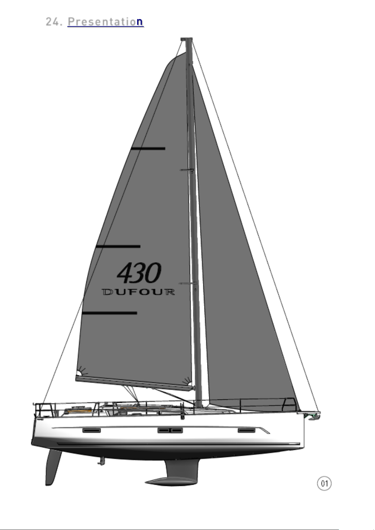
24. Presentation
ENGLISH 26-02-2019 Page 34/92 DUFOUR 430 GRAND LARGE
Page 35
25. Accommodation layout
Label
Description
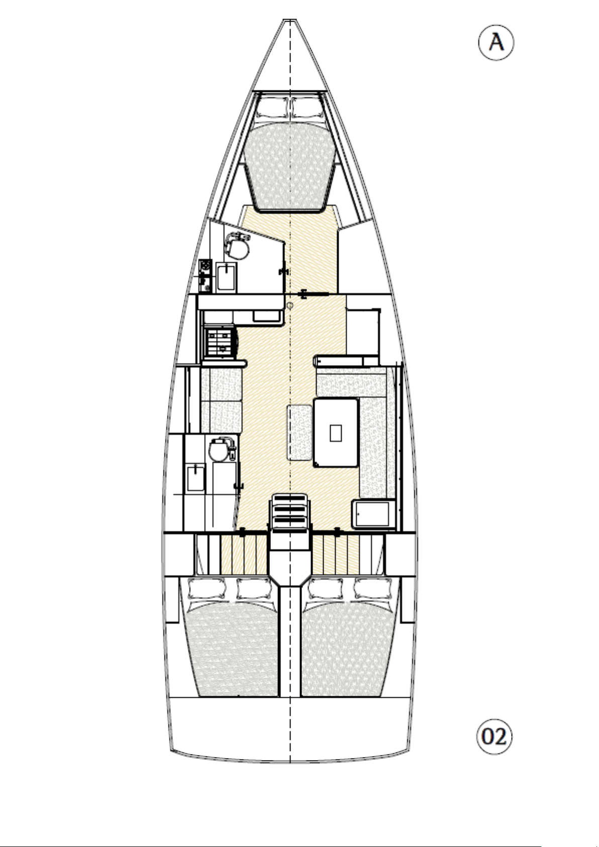
A
3-cabin front galley version
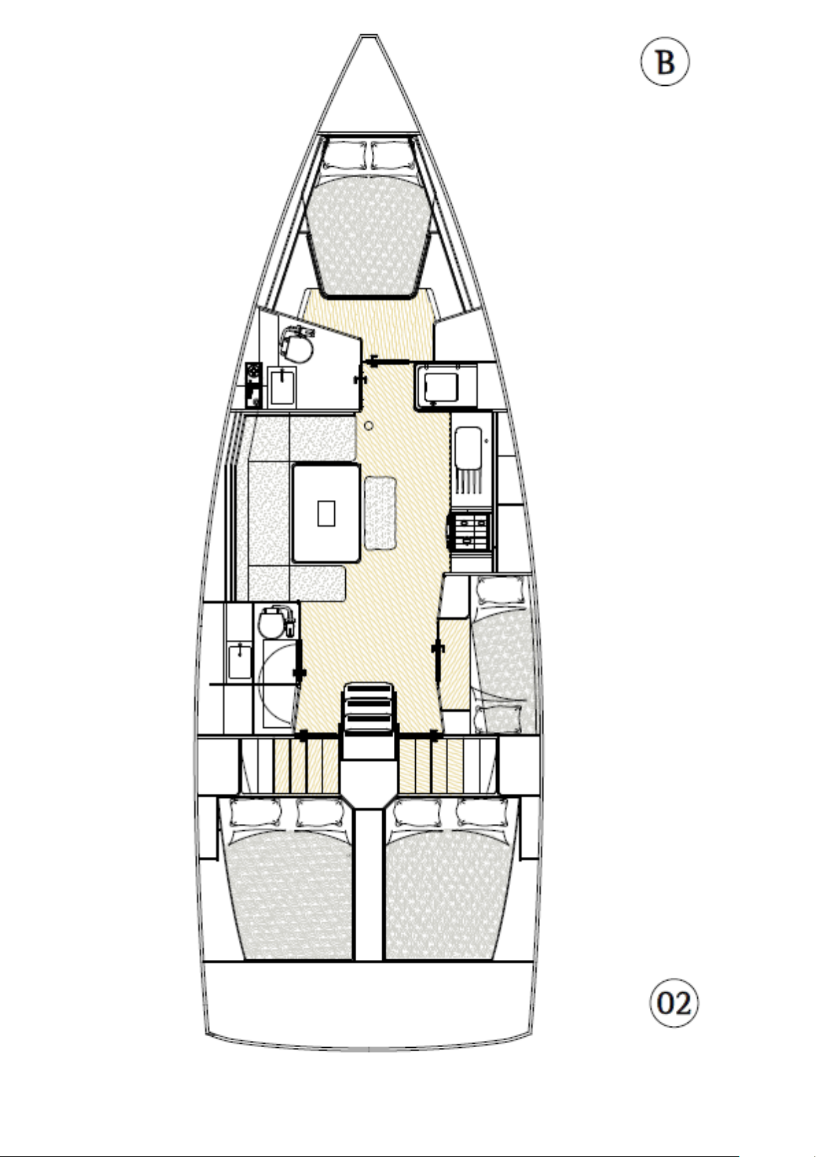
B
4-cabin long galley version
ENGLISH 26-02-2019 Page 35/92 DUFOUR 430 GRAND LARGE
Page 36
ENGLISH 26-02-2019 Page 36/92 DUFOUR 430 GRAND LARGE
Page 37
ENGLISH 26-02-2019 Page 37/92 DUFOUR 430 GRAND LARGE
Page 38
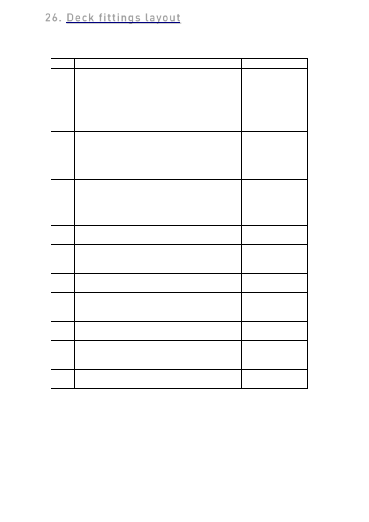
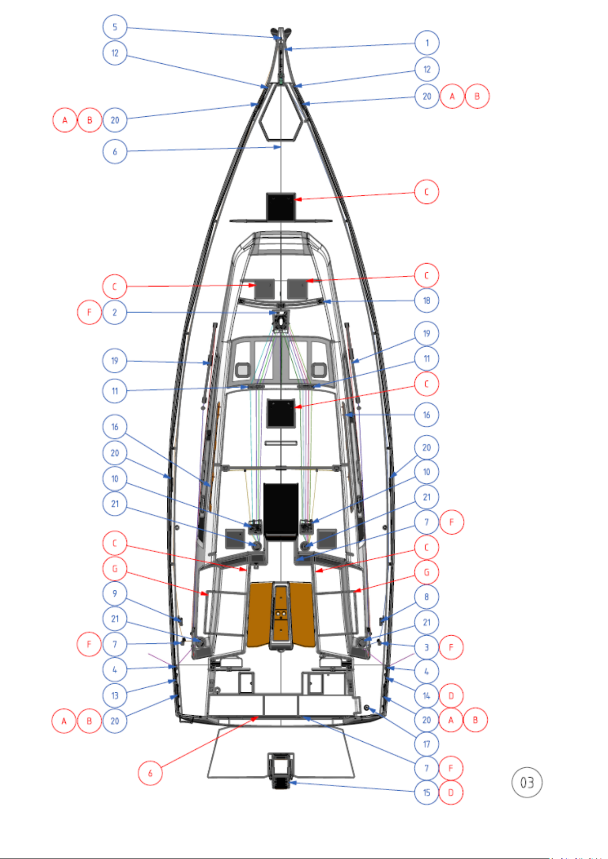
26. Deck fittings layout
No.
description
remarks
A
JACKLINE ANCHOR POINTS
Port and starboard
cleats
B
TOWING POINTS
PT/STBD
C
IT IS OBLIGATORY TO KEEP THE HATCHES CLOSED WHEN
SAILING
D "MAN OVERBOARD" REBOARDING LADDER
E LIFE RAFT STOWAGE
F ANCHOR POINT FOR SAFETY HARNESS
G LOCKER MUST BE CLOSED WHEN UNDERWAY
1
BOW ROLLER
2 WATERPROOF PAD EYE D8
Mast foot
3
FOLDING PAD EYE D8
Furling line
4
WATERPROOF PAD EYE D10
Spinnaker option
5
WATERPROOF PAD EYE D10
6 FOLDING PAD EYE D8
Releasable forestay
option
7
FOLDING PAD EYE D8
8
SINGLE CLUTCH
furling line
9
SINGLE CLUTCH
spinnaker option
10
TRIPLE CLUTCH
11
5-SHEAVE DECK ORGANIZER
12
SIMPLE PULPIT
13
PORT PUSHPIT
14
STARBOARD PUSHPIT
15
SWIMMING LADDER
16
COACH ROOF GRAB RAIL
17
FUEL DECK PLATE
18
SELF-TACKING JIB TRACK
19
GENOA TRACK
option
20
ALUMINUM MOORING CLEAT
21
WINCH T45
ENGLISH 26-02-2019 Page 38/92 DUFOUR 430 GRAND LARGE
Page 39
ENGLISH 26-02-2019 Page 39/92 DUFOUR 430 GRAND LARGE
Page 40
27. Sail plan
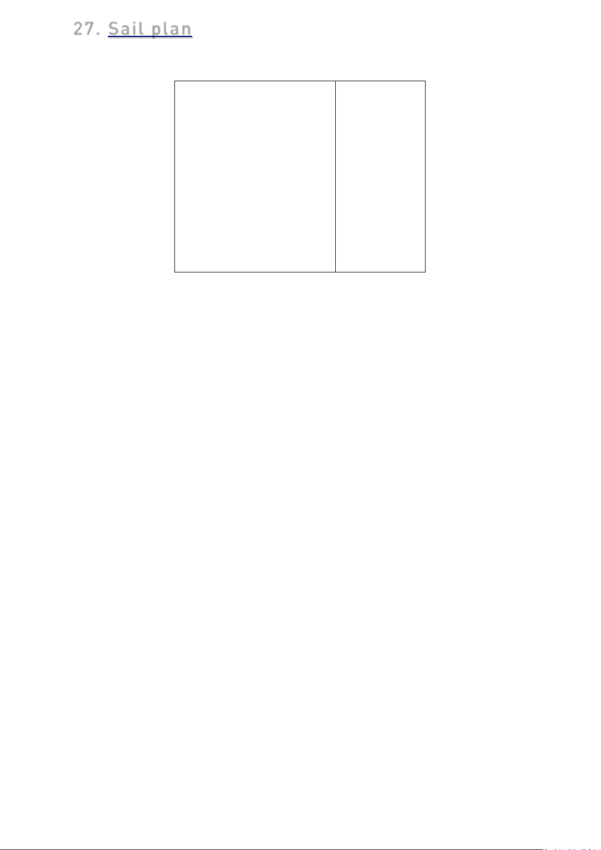
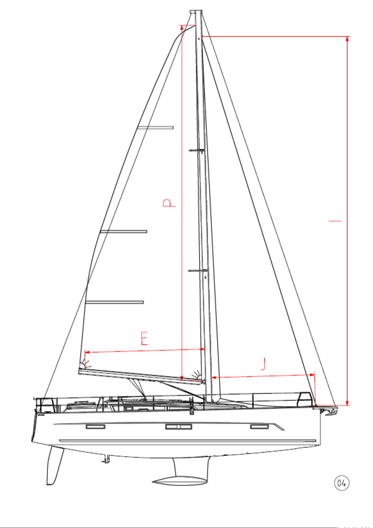
I
16.53 m
J 4.52 m
P 16.04 m
E 5.30 m
Self-tacking jib LP
3.92 m
Mainsail area
46 m²
Self-tacking jib area
29 m²
Genoa area*
38 m²
* Option
ENGLISH 26-02-2019 Page 40/92 DUFOUR 430 GRAND LARGE
Page 41
ENGLISH 26-02-2019 Page 41/92 DUFOUR 430 GRAND LARGE
Page 42
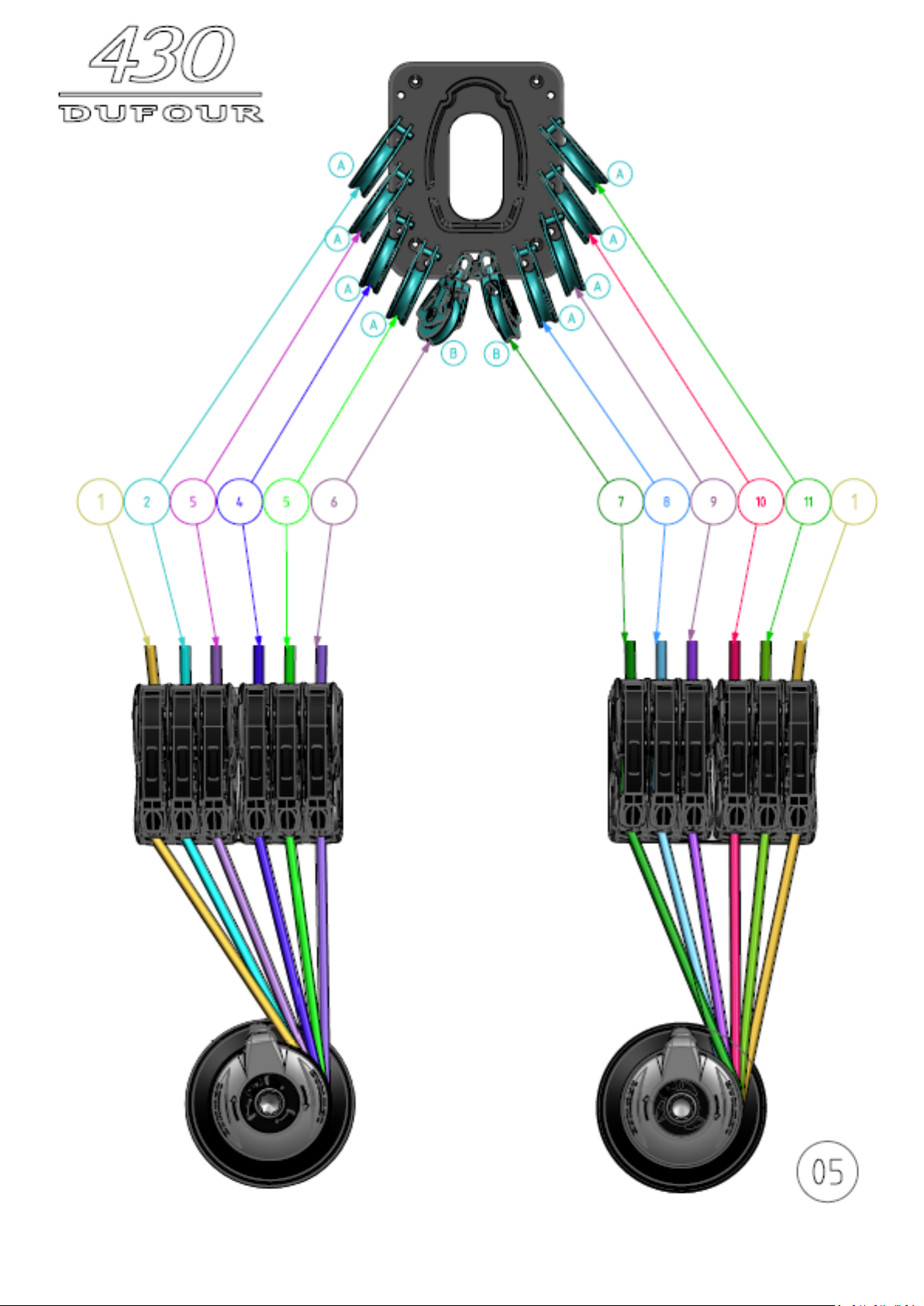
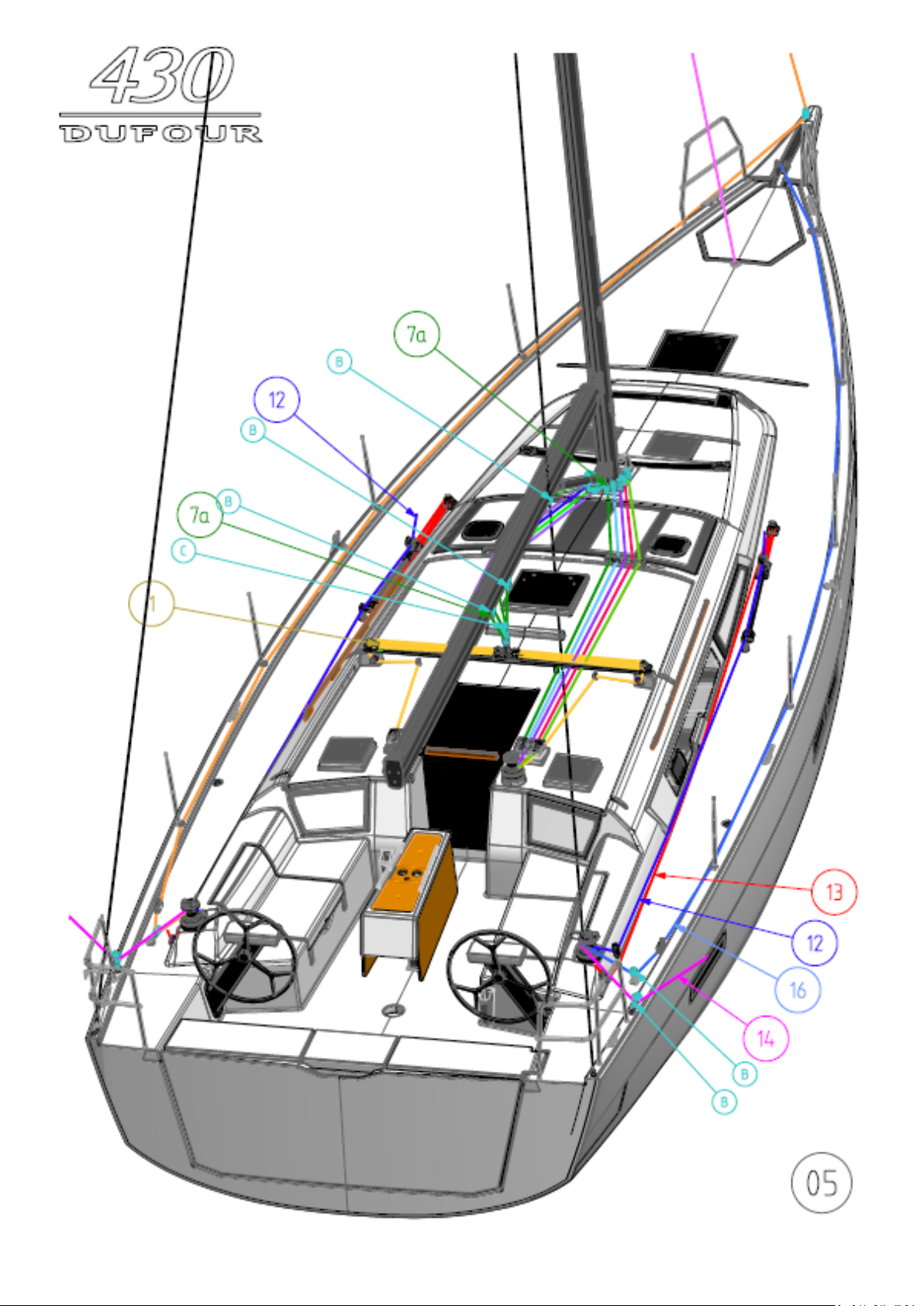
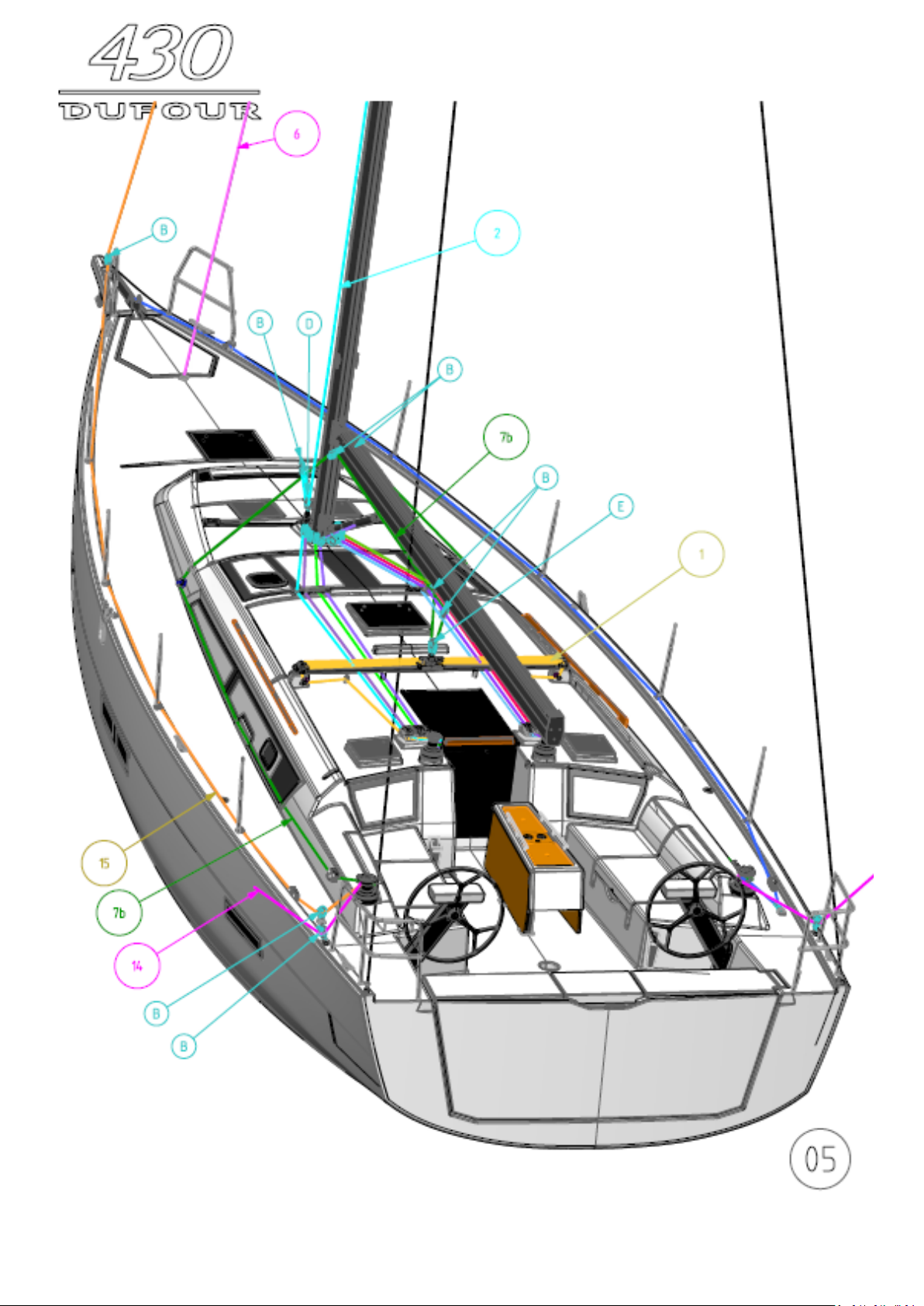
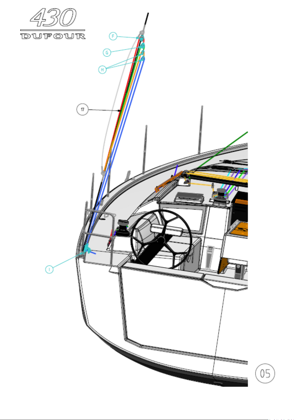
28. Running rigging, sheets and halyards layout
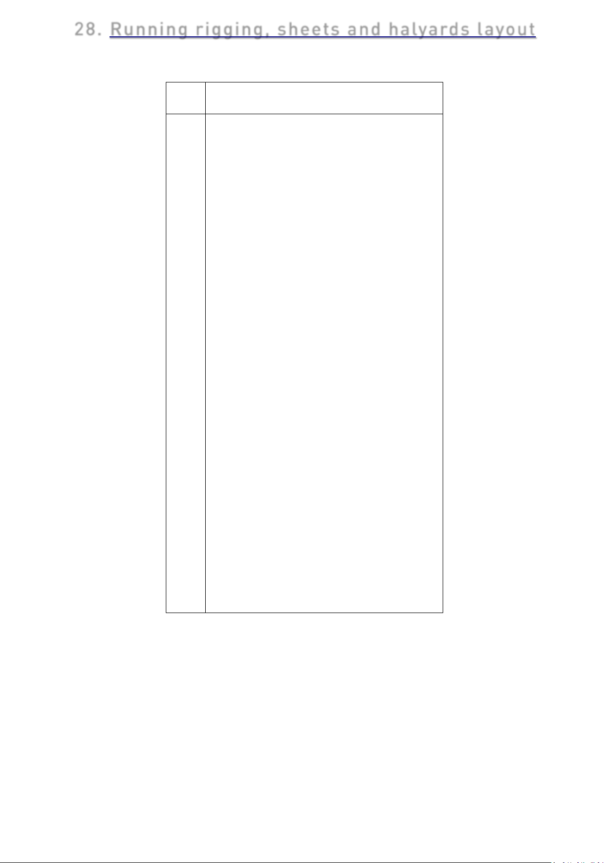
Labe
1
Mainsail traveller sheet*
2
Self-tacking jib sheet
3
Releasable forestay*
5
Reef 1
6
Rigid boom vang
7a
Standard mainsheet
7b
German System mainsheet*
8
Reef 2
9
Mainsail foot
10
Mainsail halyard
11
Code 0/Spinnaker halyard
12
Genoa sheet*
13
Genoa traveller sheet*
14
Code 0 sheet*
15
Code 0 tack*
16
Furling line
17
Backstay hoist*
*
Option
A
D80 MAST FOOT BLOCK
B
D72 SYNC BLOCK
C
D90 FIDDLE BLOCK
D
D72 BECKET BLOCK
E
D90 SYNC BLOCK
F
D60 SYNC BLOCK
G
D50 SYNC BLOCK
H
D40 SINGLE BLOCK
I
D60 BECKET - CLEAT BLOCK
l Description standard mast
4
Self-tacking jib / Genoa halyard
ENGLISH 26-02-2019 Page 42/92 DUFOUR 430 GRAND LARGE
Page 43
ENGLISH 26-02-2019 Page 43/92 DUFOUR 430 GRAND LARGE
Page 44
ENGLISH 26-02-2019 Page 44/92 DUFOUR 430 GRAND LARGE
Page 45
ENGLISH 26-02-2019 Page 45/92 DUFOUR 430 GRAND LARGE
Page 46
ENGLISH 26-02-2019 Page 46/92 DUFOUR 430 GRAND LARGE
Page 47
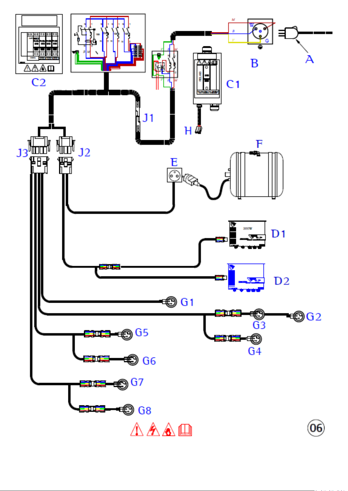
29. 220V circuit diagram
Label
Description
Facilities
A B 220V Shore cable**
Shore AC connection
C1
Aft cabin cabinet with main circuit breaker
F
Water heater
G
220V 10A outlets
H
Voltage presence connector
J1
3-way distribution connector
J2
6-way distribution connector
J3
12-way distribution connector
Electrical wiring colours
b
light blue
g
green
m
brown
n
black
r
red
v
green/yellow
w
white
*
Option
**
Not supplied
C2
D1
D2
E
Chart table cabinet
Standard auxiliary - engine charger
Optional charger – Windlass*
Watertight water heater socket
ENGLISH 26-02-2019 Page 47/92 DUFOUR 430 GRAND LARGE
Page 48
ENGLISH 26-02-2019 Page 48/92 DUFOUR 430 GRAND LARGE
Page 49
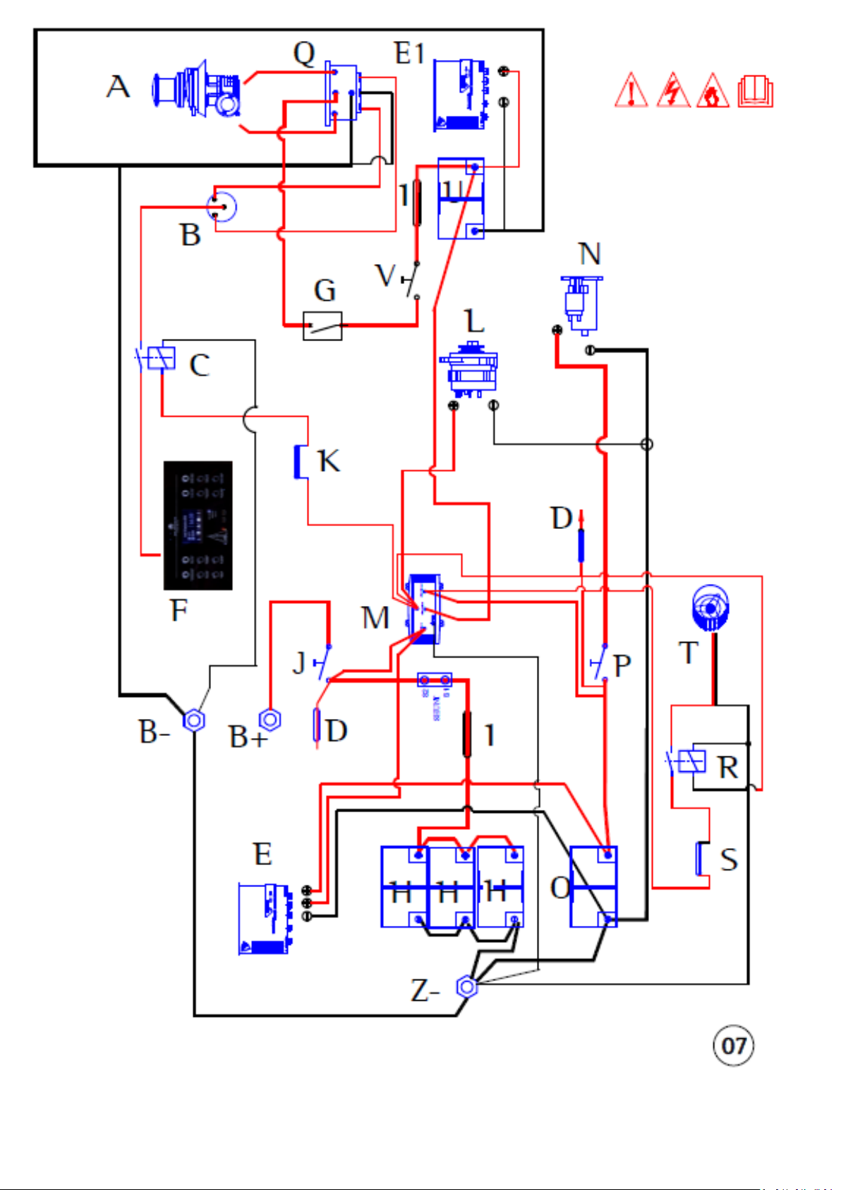
.
Description
A Windlass*
B Windlass control* (remote)
C
Remote control relay*
D
8 A fuse – battery levels
E
Standard charger
E1
Windlass charger*
F 12V distribution panel
G Single-pole 110 A circuit breaker*
H
Auxiliary batteries
I
160A fuse
J Auxiliary batteries switch
K 5A fuse*
L Alternator
M Distributor
N Starter
O Engine battery
P Engine battery isolator
Q Windlass relay*
R Bilge fan relay
S 5A fuse
T Bilge fan
U Windlass battery*
V Windlass battery isolator*
B-
Terminal - (electrical panel)
T+
Terminal + (electrical panel)
Z-
Terminal - (technical area)
* Option
30. Charging and power system diagram
Label
ENGLISH 26-02-2019 Page 49/92 DUFOUR 430 GRAND LARGE
Page 50
ENGLISH 26-02-2019 Page 50/92 DUFOUR 430 GRAND LARGE
Page 51
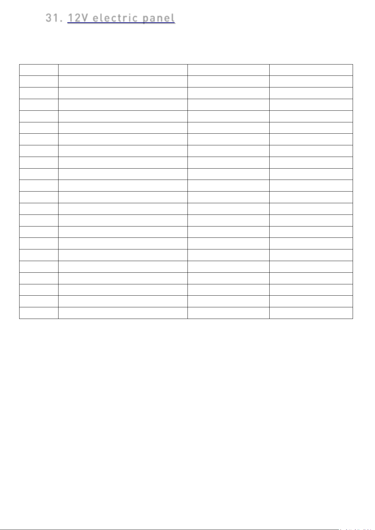
31. 12V electric panel
Label
Functions
Fuse code
Cut-off value
1
Navigation lights
FU15
5A Steaming light
FU17
5A
Mooring light
FU16
5A
2
Auto-pilot
FU13
20A
3
Windlass control
FU14
10A
4
Deck light
FU8
10A
5
Instruments Navigation 1
FU7
10A
Instruments Navigation 2
FU9
20A
6
Audio
FU10
10A
Cabin USBs
FU12
10A
7
Saloon lights
FU4
15A
8
Water pump unit
FU5
10A
Shower pumps
FU6
10A
9
Interior fridge
FU11
10A
10
Cabin lights
FU2
15A
11
Bilge pump
FU1
15A
12
Cockpit fridge
FU3
10A
13
Display screen
FU18
2A
14
Source indicator
AC supply
15
Frontal USB socket
16
Navigation lights indicator
N.B.: depending on the type of boat or options, some features may not be active.
ENGLISH 26-02-2019 Page 51/92 DUFOUR 430 GRAND LARGE
Page 52
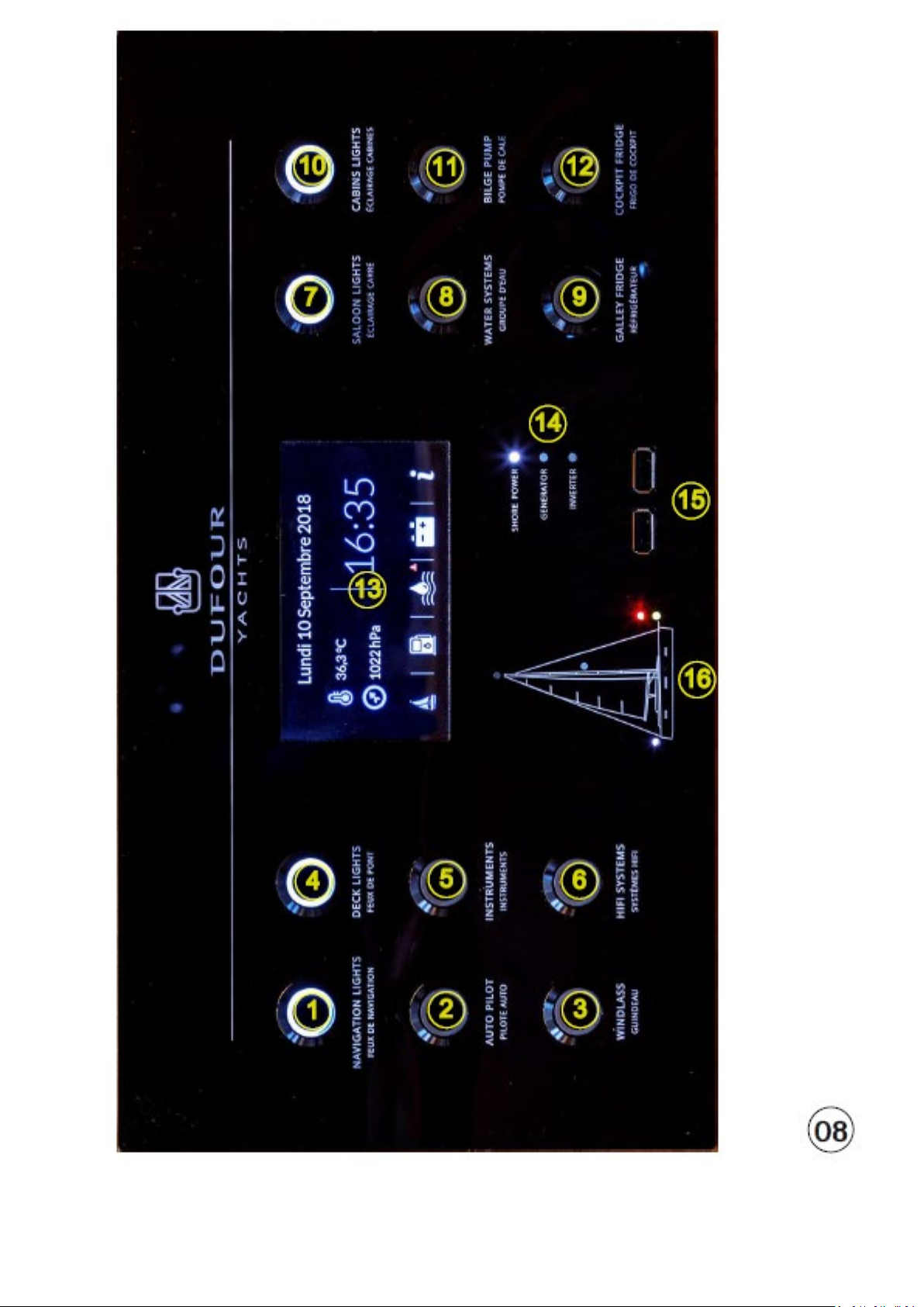
ENGLISH 26-02-2019 Page 52/92 DUFOUR 430 GRAND LARGE
Page 53
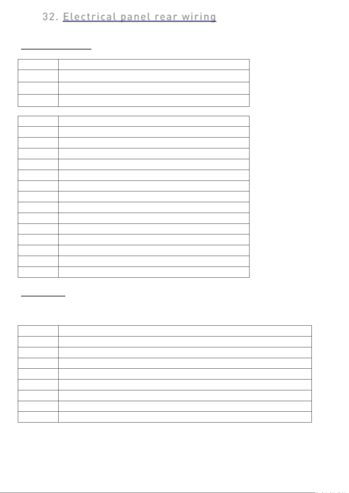
32. Electrical panel rear wiring
Position
Status
Label
Function
S1
Sailing Instruments
S2
Deck light
S3
Cockpit fridge
S4
Windlass control
S5
Audio / USB sockets
S6
Auto-pilot
S7
Interior fridge
S8
Cabin Lights
S9
Saloon Lights
S10
Navigation lights
S11
Bilge pump
S12
Water / shower pump unit
S13
Steaming light
S14
Mooring light
Label
Function
K1
AC Source Indicator – Shore Cable
K2
AC Source Indicator – Inverter
K3
AC Source Indicator – Generator
K4
Auxiliary and Optional battery installation voltage indicator
K5
Greywater holding tank level indicator
K6
CAN bus
K7
RS485 bus
K8
LIN bus
Function switches
0
I
II
Disabled function
Forced Mode Function
Panel Mode Function – activated by the front
Connectors
K connectors
N.B.: depending on the type of boat or options, some features may not be active
ENGLISH 26-02-2019 Page 53/92 DUFOUR 430 GRAND LARGE
Page 54
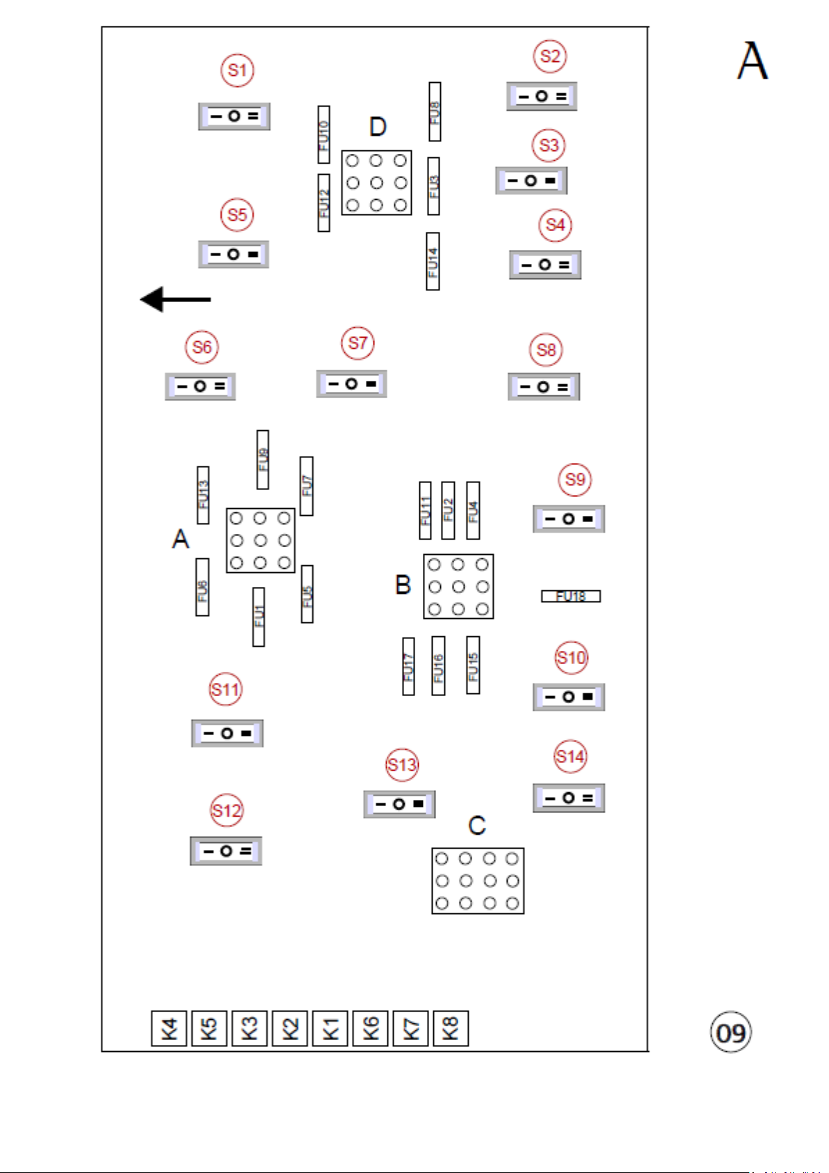
ENGLISH 26-02-2019 Page 54/92 DUFOUR 430 GRAND LARGE
Page 55
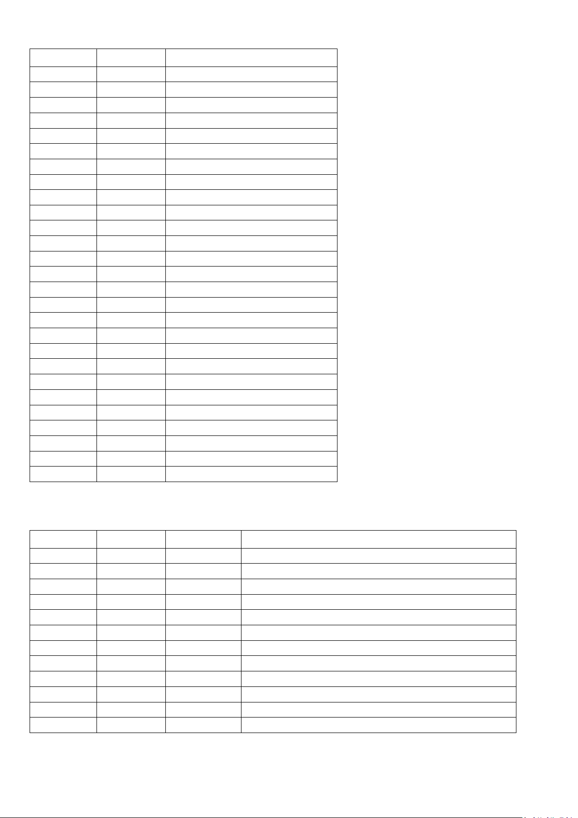
Power Connectors – A – B – D
Label
Type
Definition
A1
Outlet
Water pump unit
A2
Inlet
AUXILIARY BATTERIES
A3
Outlet
Interior fridge
A4
Outlet
Bilge pump
A5
Inlet
AUXILIARY BATTERIES
A6
Outlet
Navigation Instruments 2
A7
Outlet
Shower pump
A8
Inlet
GND
A9
Outlet
Auto-pilot
B1
Outlet
Navigation lights
B2
Inlet
AUXILIARY BATTERIES
B3
Outlet
Saloon Lights
B4
Outlet
Mooring light
B5
Inlet
AUXILIARY BATTERIES
B6
Outlet
Cabin Lights
B7
Outlet
Steaming light
B8
Inlet
GND
B9
Outlet
Audio System
D1
Outlet
Deck light
D2
Inlet
AUXILIARY BATTERIES
D3
Outlet
Navigation Instruments 1
D4
Outlet
Cockpit Fridge
D5
Inlet
AUXILIARY BATTERIES
D6
Outlet
USB sockets
D7
Outlet
Windlass control
D8
Inlet
GND
Label
Type
Value
Definition
C1
Inlet
-50 mV
100A shunt
C2
Inlet
+50 mV
100A shunt
C3
Inlet
0-180Ω
No.3 WATER Tank Level
C4
Inlet
0-180Ω
No.1 WATER Tank Level
C5
Inlet
��0-180Ω
No.1 FUEL Tank Level
C6
Inlet
0-14V
Engine Battery Voltage
C7
Inlet
0V
GND
C8
Inlet
0-180Ω
No.2 FUEL Tank Level
C9
Inlet
0-180Ω
No.2 WATER Tank Level
C10
Inlet
0-180Ω
No.1 Holding Tank Level
C11
Inlet
0-180Ω
No.2 Holding Tank Level
C12
Inlet
0-180Ω
No.3 Holding Tank Level
D9 FREE
Signal Connectors – C
N.B.: depending on the type of boat or options, some features may not be active
ENGLISH 26-02-2019 Page 55/92 DUFOUR 430 GRAND LARGE
Page 56
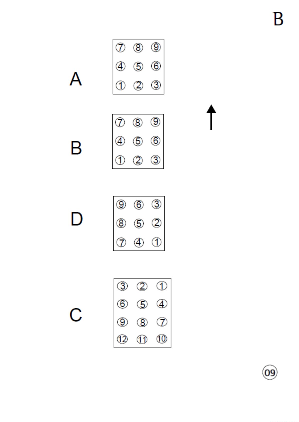
ENGLISH 26-02-2019 Page 56/92 DUFOUR 430 GRAND LARGE
Page 57
33. 12V electrical installation diagram
Label.
Description
1
Windlass*
2
Windlass relay*
3
Windlass remote control*
4
Navigation lights*
5
Fresh-water gauge
6
Reading lights
7
Water pump unit
8
Saloon speaker*
9
12V electric panel
10
11
Flexible LED switch
USB socket
12
Submersible bilge pump
13
Steaming light
14
Mooring light
15
Saloon downlight
16
Saloon downlight switch
17
Galley downlight switch
18
Galley downlights
19
Refrigeration unit
20
Shower waste pump
21
Windlass battery*
22
Windlass circuit breaker*
23
Bathroom downlight
24
Courtesy lights
25
Engine battery
26
Auxiliary batteries
27
Fuel gauge
28
Motor fan
29
Alternator
30
Engine and auxiliary battery isolator
31
Distributor
32
Starter
33
NA
34
Seawater pump
35
Exterior speaker*
36
Steering compass
37
Auto-pilot motor*
38
Courtesy lights switch
39
Seawater pump switch
*
Option
A- 3-cabin front galley version
B- 4-cabin long galley version
ENGLISH 26-02-2019 Page 57/92 DUFOUR 430 GRAND LARGE
Page 58
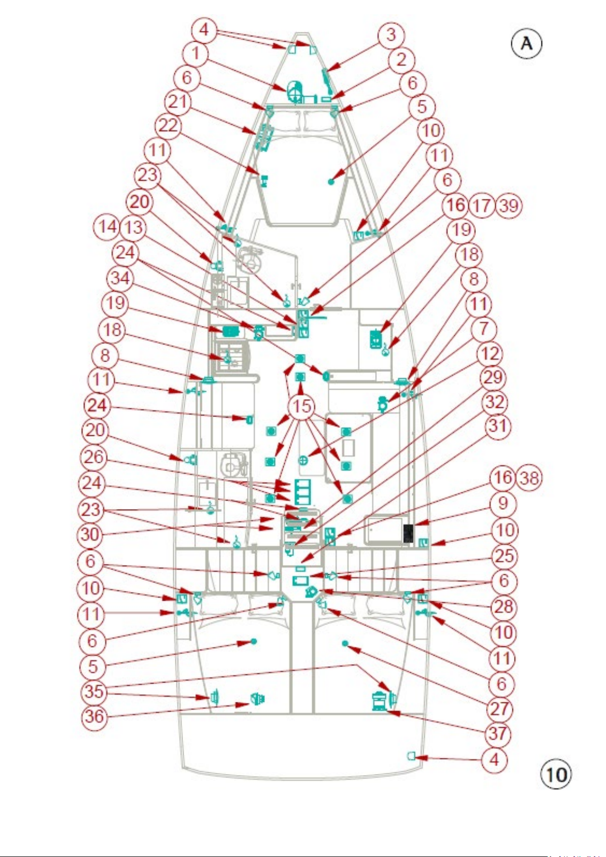
ENGLISH 26-02-2019 Page 58/92 DUFOUR 430 GRAND LARGE
Page 59
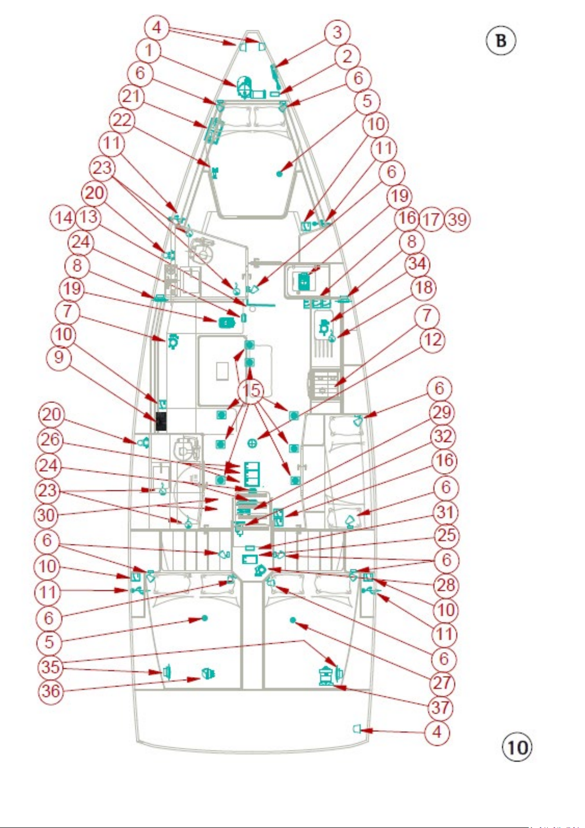
ENGLISH 26-02-2019 Page 59/92 DUFOUR 430 GRAND LARGE
Page 60
11- 220V electrical installation diagram
l
Description
1
220 V (or 110 V) power socket
2
Water heater
3 Battery charger
4 Main circuit breaker box
5 6
Shore AC connection
7 8 220V Microwave power socket*
9 Optional charger – Windlass*
*
Option
A- 3-cabin front galley version
B- 4-cabin long galley version
Labe
E/F/G connectors
General circuit breaker box
ENGLISH 26-02-2019 Page 60/92 DUFOUR 430 GRAND LARGE
Page 61
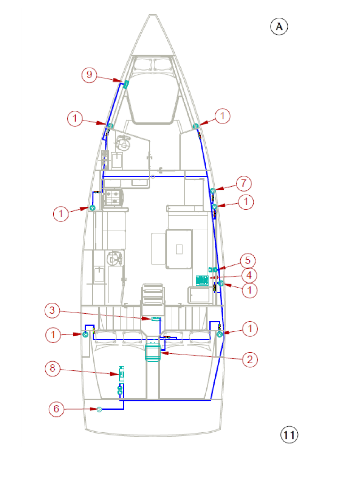
ENGLISH 26-02-2019 Page 61/92 DUFOUR 430 GRAND LARGE
Page 62
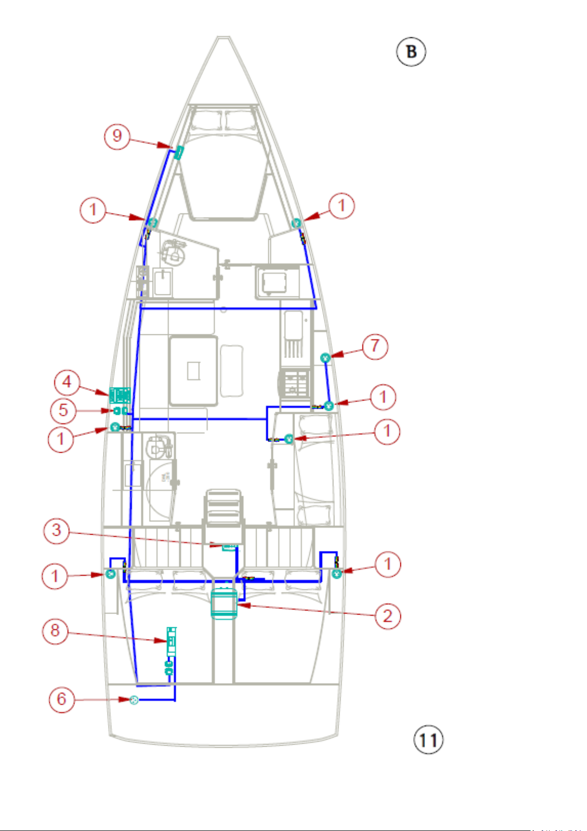
ENGLISH 26-02-2019 Page 62/92 DUFOUR 430 GRAND LARGE
Page 63
Labe
l
Description
Blade fuse 1A: with gas solenoid valve*
Blade fuse 10A: heating option*
Blade fuse 5A: bow thruster option*
Blade fuse 10A: VHF option*
E
Zone E - 220V General electrical box
F
Zone F - 12V
G
Zone F: 220V
*
OPTION
12- Fuse location diagram
A- 3-cabin front galley version
B- 4-cabin long galley version
A
B
C
D
Zone A - 12V
Strip fuse 500A: optional bow thruster*
Differential circuit-breaker 110A: windlass*
Zone B - 12V
Blade fuse 30A: inverter option*
Resettable circuit breaker type C 16A: Electric toilets*
Zone C - 12V
Blade fuse 10A: bilge fan
Zone D - 12V
Strip fuse 160A: panel protection
16A/30mA differential circuit breaker: general protection
Phase/Neutral thermomagnetic circuit breaker 10A: water heater
protection
Phase/Neutral thermomagnetic circuit breaker 10A: charger protection
Phase/Neutral thermomagnetic circuit breaker 10A: 220V socket protection
35A strip fuse: Electric aft gate*
ENGLISH 26-02-2019 Page 63/92 DUFOUR 430 GRAND LARGE
General circuit breaker: shore protection
Page 64
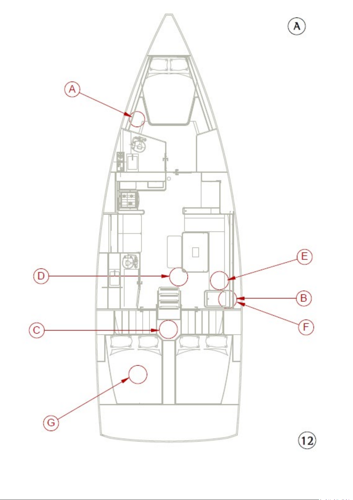
ENGLISH 26-02-2019 Page 64/92 DUFOUR 430 GRAND LARGE
Page 65
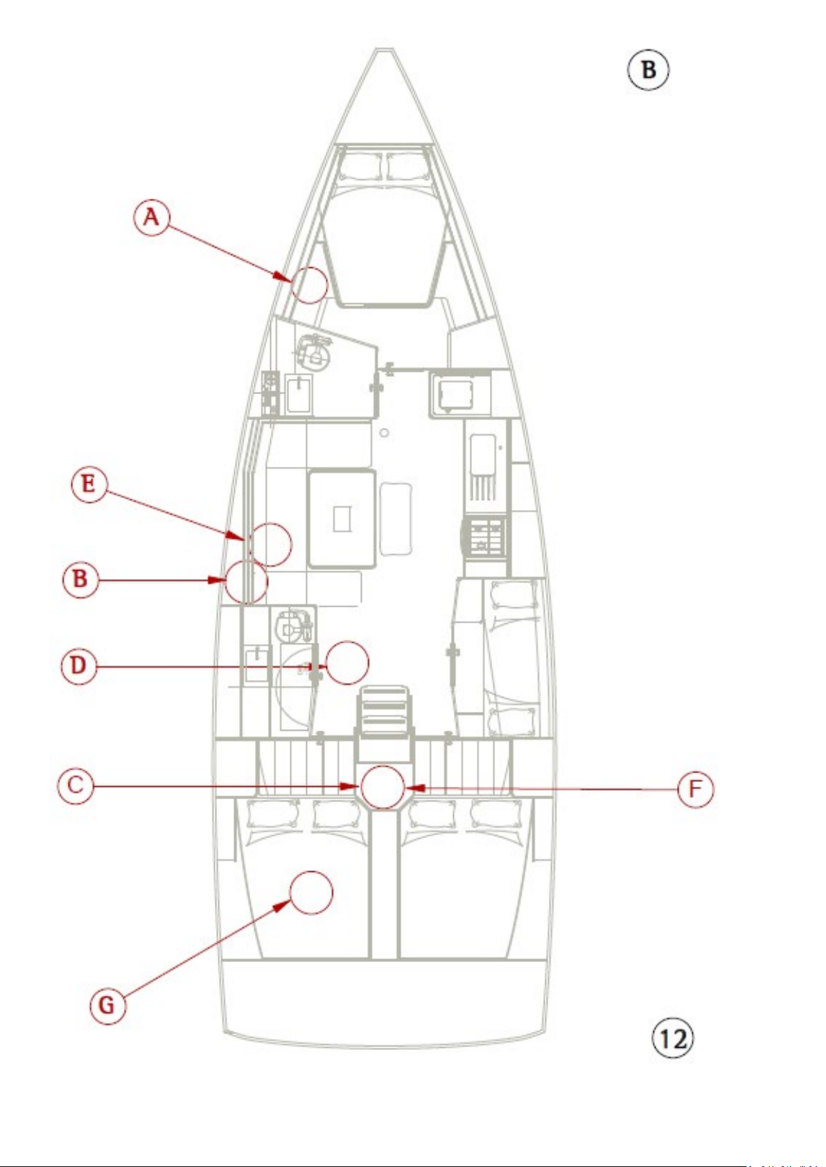
ENGLISH 26-02-2019 Page 65/92 DUFOUR 430 GRAND LARGE
Page 66
13 - Steering system diagram
l
Description
1
Rudder blade + stock
2
Rudder trunk
3
Lower bearing
4
Lower bearing and rudder rings
5
Top bearing
6
Section stop
7
Steering wheel
8
Autopilot motor*
9
Helm angle indicator*
10
Emergency tiller
11
80 degree segment
12
Port and starboard helm pedestals
*
Option
Labe
ENGLISH 26-02-2019 Page 66/92 DUFOUR 430 GRAND LARGE
Page 67
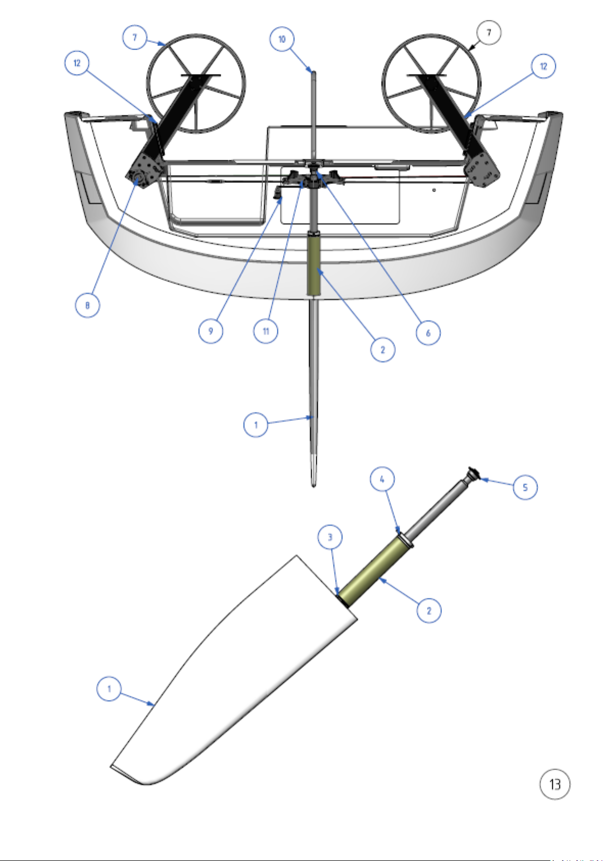
ENGLISH 26-02-2019 Page 67/92 DUFOUR 430 GRAND LARGE
Page 68
14 - Gas system diagram
l
Description
1 1.8 kg gas cylinder**
2 CE shut-off valve (Fr. or Ger.)
3
30mbar CE regulator valve (Fr. or Ger.) / pressure
gauge
4
Medium-length connecting hose
5
Spacer/tube 6 x 8
6 Watertight bulkhead fitting
7 PVC pipe
8 6 x 8 copper pipe
9 CE gas shut-off valve
10
Long connection hose
*
Option
**
Not supplied
A- 3-cabin front galley version
B- 4-cabin long galley version
Labe
11
12
13
14
15
16
Cooker/Oven
Bulkhead gas locker
"T" gas connector*
Foldaway*
Split black sleeve
Gas foldaway hose *
ENGLISH 26-02-2019 Page 68/92 DUFOUR 430 GRAND LARGE
Page 69
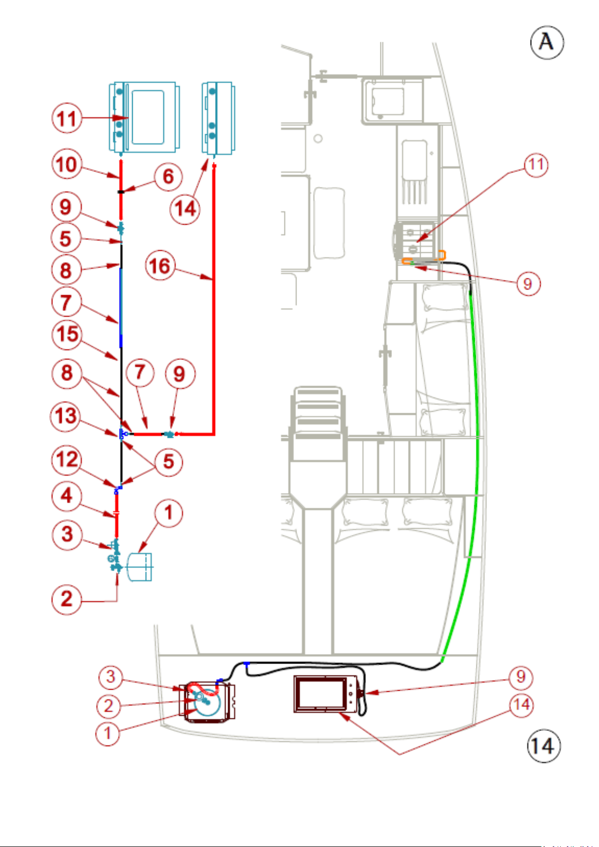
ENGLISH 26-02-2019 Page 69/92 DUFOUR 430 GRAND LARGE
Page 70
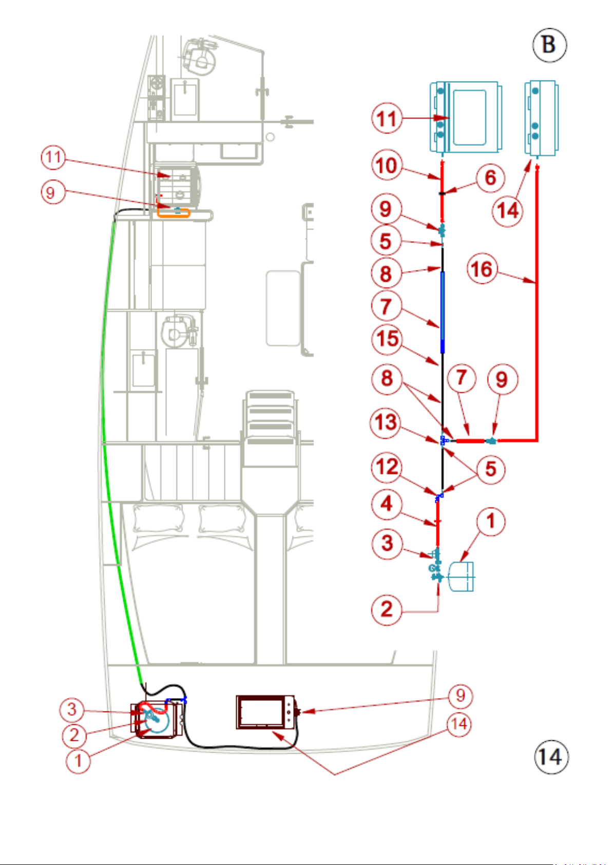
ENGLISH 26-02-2019 Page 70/92 DUFOUR 430 GRAND LARGE
Page 71
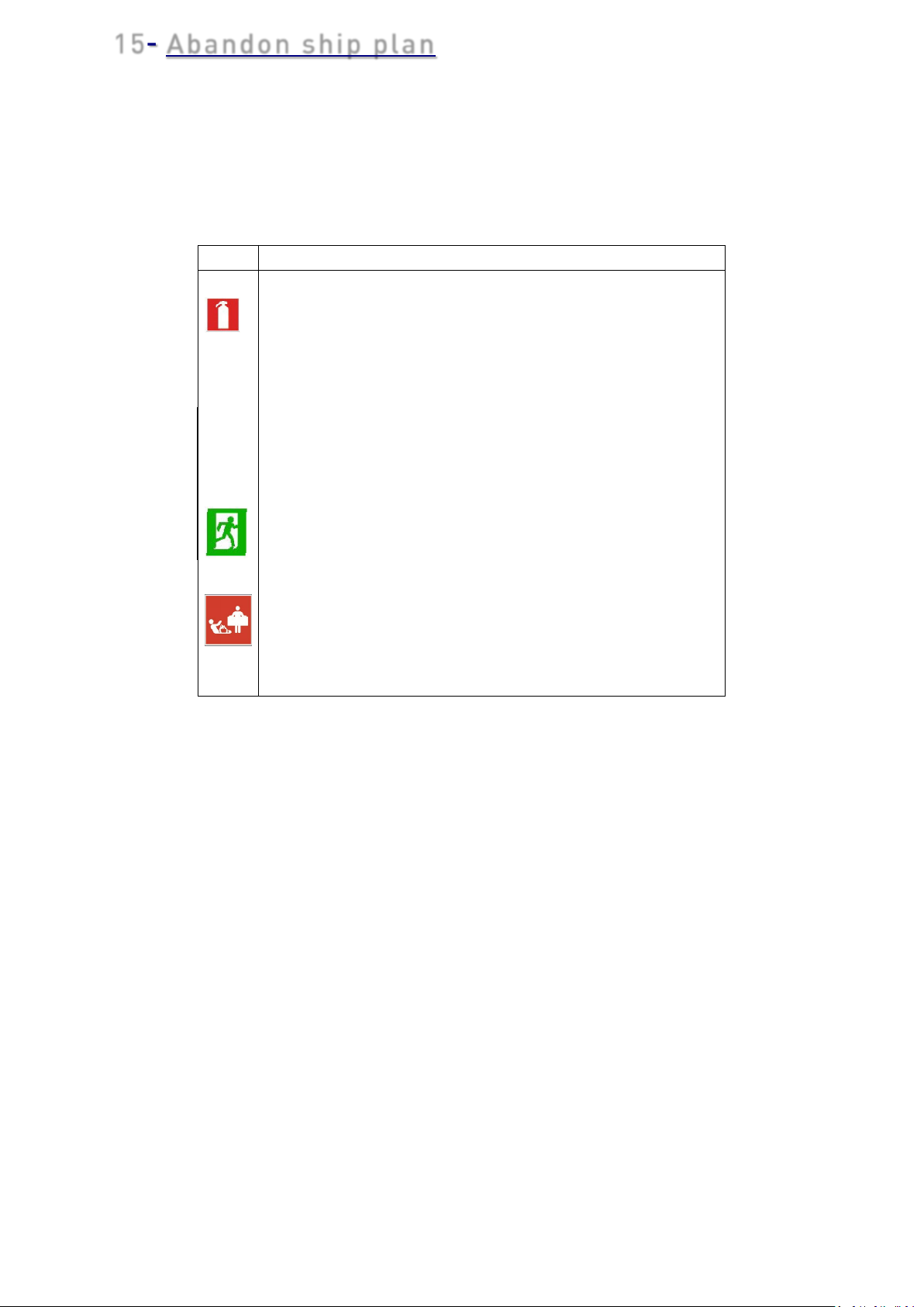
15- Abandon ship plan
Label
Description
Recommended fire-extinguisher locations
2
1 kg powder fire extinguisher 5A/34B **
SD
Fire Detector - recommended location
Fire blanket (recommended location)
**
Not supplied
A- 3-cabin front galley version
B- 2-cabin long galley version
1 1 kg powder fire extinguisher 5A/34B **
Wh Engine compartment extinguisher hole
Emergency exit
ENGLISH 26-02-2019 Page 71/92 DUFOUR 430 GRAND LARGE
Page 72
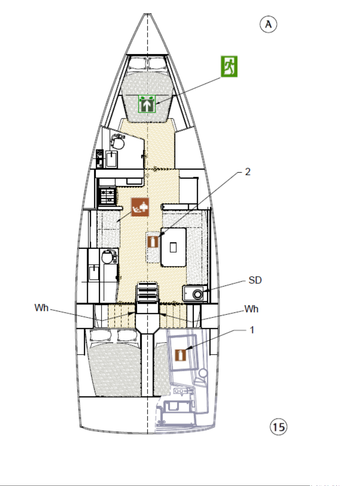
ENGLISH 26-02-2019 Page 72/92 DUFOUR 430 GRAND LARGE
Page 73
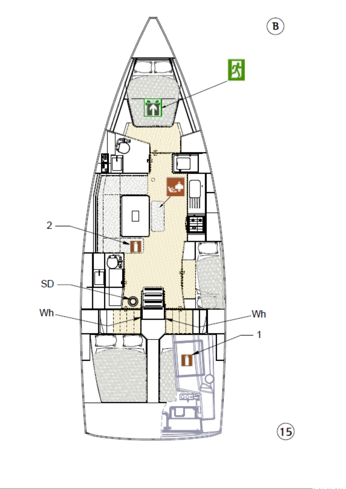
ENGLISH 26-02-2019 Page 73/92 DUFOUR 430 GRAND LARGE
Page 74
16- Freshwater system diagram
l
Description
1
Filler deck plate
2
Filler hose
3
Vent
4
Vent hose
6
Stern water tank 250 L
7
Hot water pipe
8
Cold water pipe
9
Pressurized water pump unit
10
Fresh-water pump
11
Water heater
12
Head shower single-lever mixer tap
13
Galley single-lever mixer tap
14
Deck shower
15
Water tank selection valves
16
1/2" 3-way manifold
17
¾" male brass cap
18
1/4 turn FF 1/2” valve
19
¾" WX F connector
20
½" WX M connector
* OPTION
A- 3-cabin front galley version
B- 4-cabin long galley version
Labe
5
21
22
Fore water tank, 180 L
Seawater foot pump
Exterior sink tap*
ENGLISH 26-02-2019 Page 74/92 DUFOUR 430 GRAND LARGE
Page 75
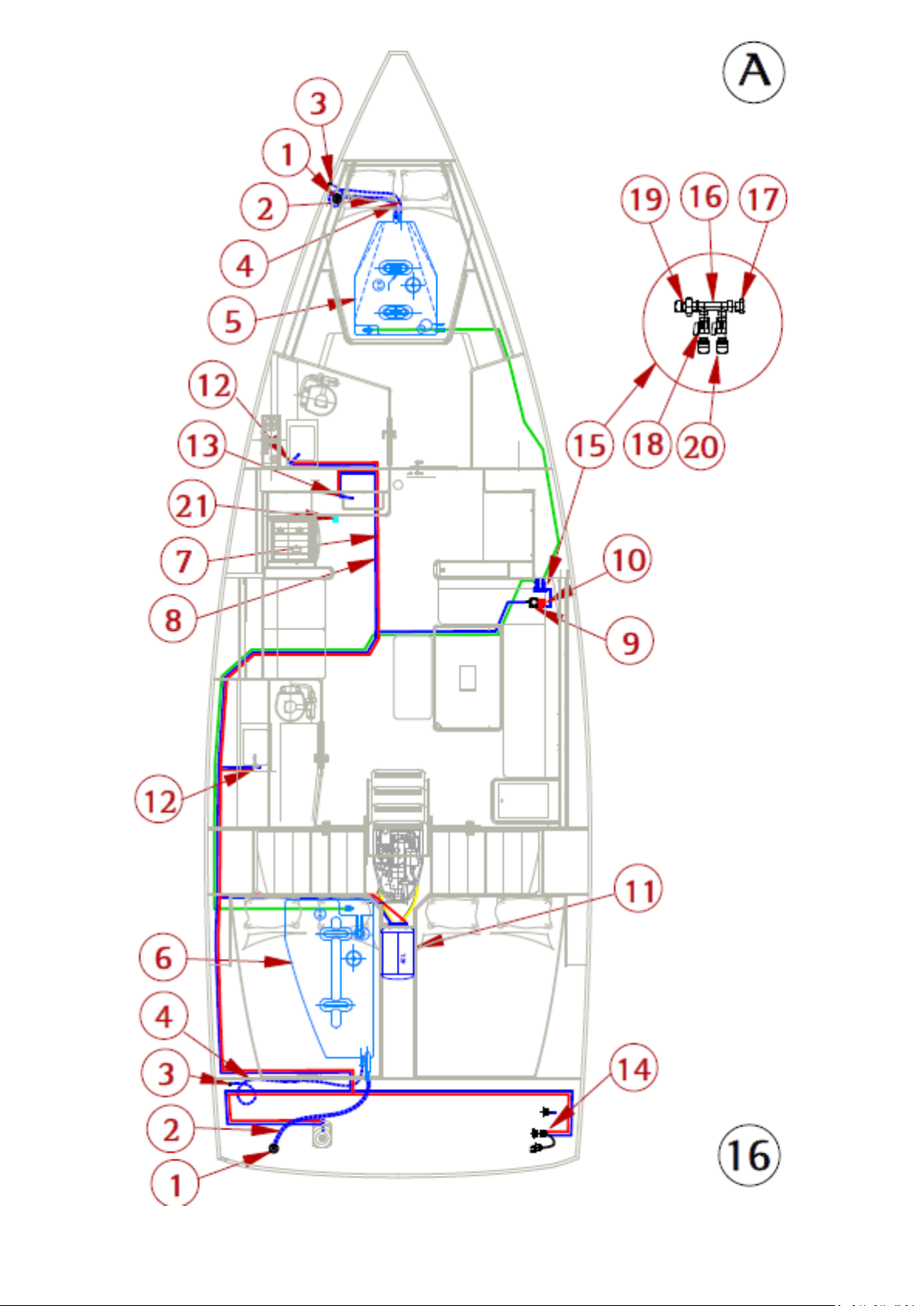
ENGLISH 26-02-2019 Page 75/92 DUFOUR 430 GRAND LARGE
Page 76
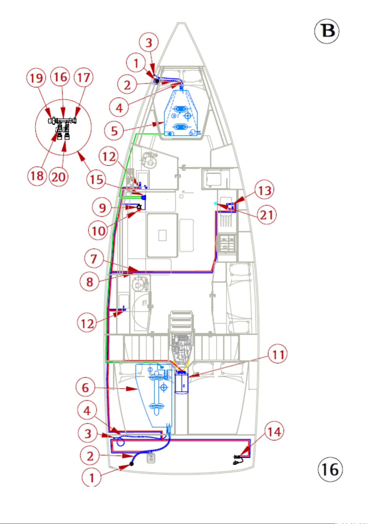
ENGLISH 26-02-2019 Page 76/92 DUFOUR 430 GRAND LARGE
Page 77
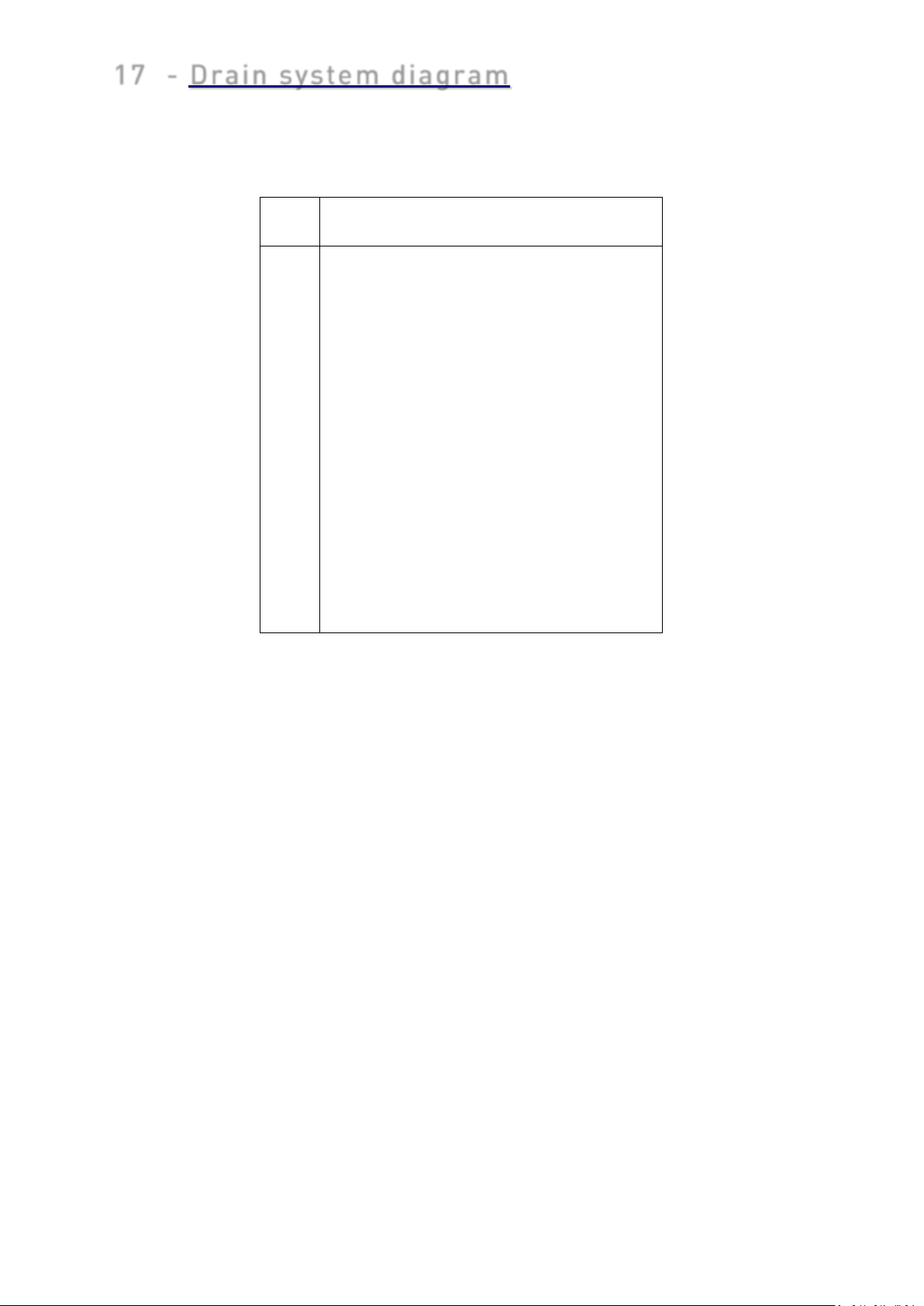
l
Description
Electric bilge pump
1 Ø25 discharge hose
2 Submersible bilge pump
3 Skin fitting 1"
Manual bilge pump
4 D25 Strainer with non-return valve
5 Ø25 discharge hose
6 7
Skin fitting 1 "
17 - Drain system diagram
Labe
Manual bilge pump
ENGLISH 26-02-2019 Page 77/92 DUFOUR 430 GRAND LARGE
Page 78
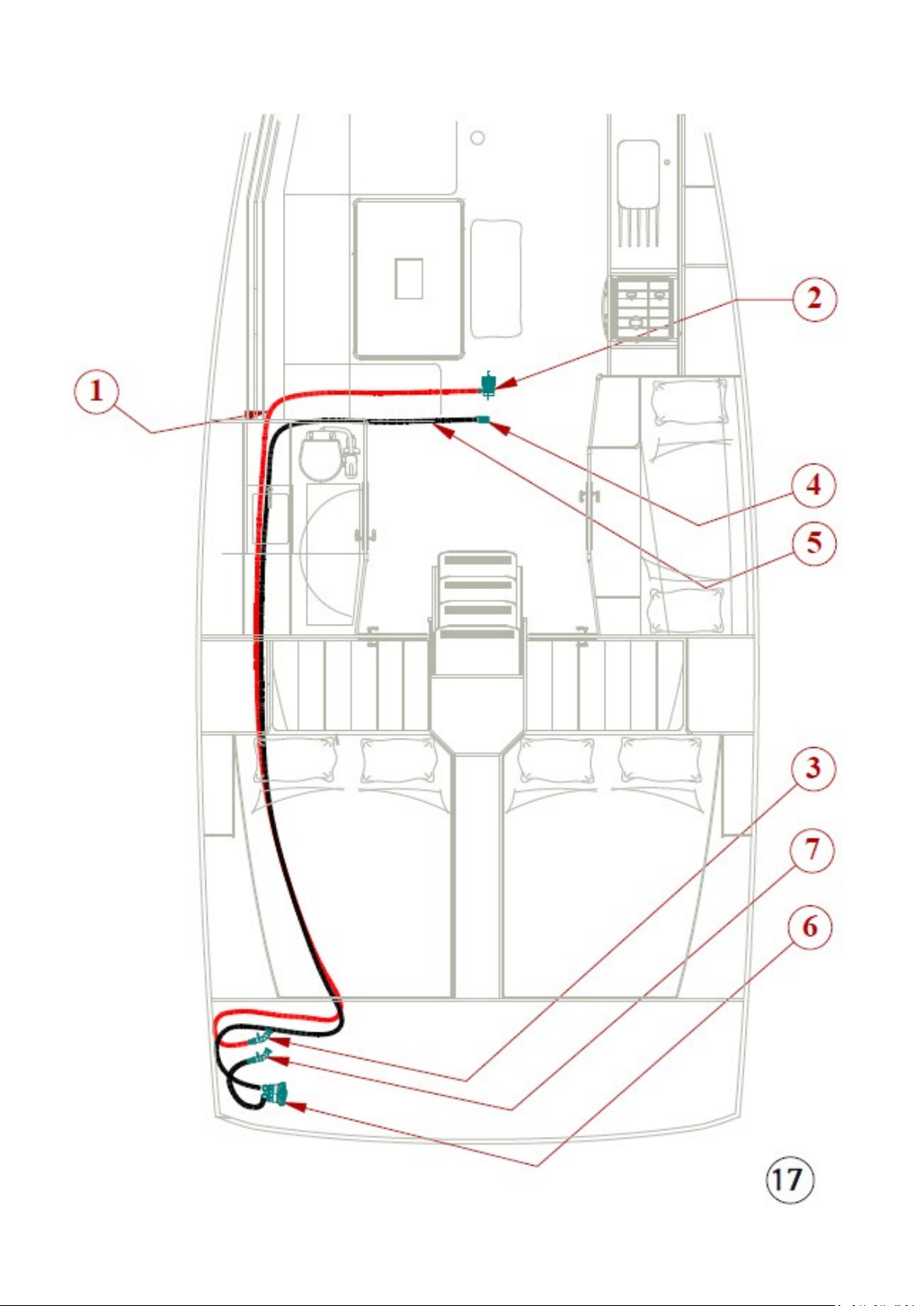
ENGLISH 26-02-2019 Page 78/92 DUFOUR 430 GRAND LARGE
Page 79
l
Description
Ø
Skin fittings + seacocks
1 Galley sink discharge
1"
6
Washbasin and shower discharge
Cockpit discharge
2’’
8
Life raft locker discharge
1’’ 9
Chain locker discharge
1" 10
Electric bilge pump discharge
1"
11 Manual bilge pump discharge
1"
*
Option
18 - Skin fitting location diagram
A - 3-cabin front galley version
B - 4-cabin long galley version
Labe
2
3
4
5
7 Exterior sink discharge and scupper 1’’
Toilet sea-water intake
Toilet discharge
Seawater pump socket
Skin fitting
1"
3/4"
1-1/2"
1/2"
ENGLISH 26-02-2019 Page 79/92 DUFOUR 430 GRAND LARGE
Page 80
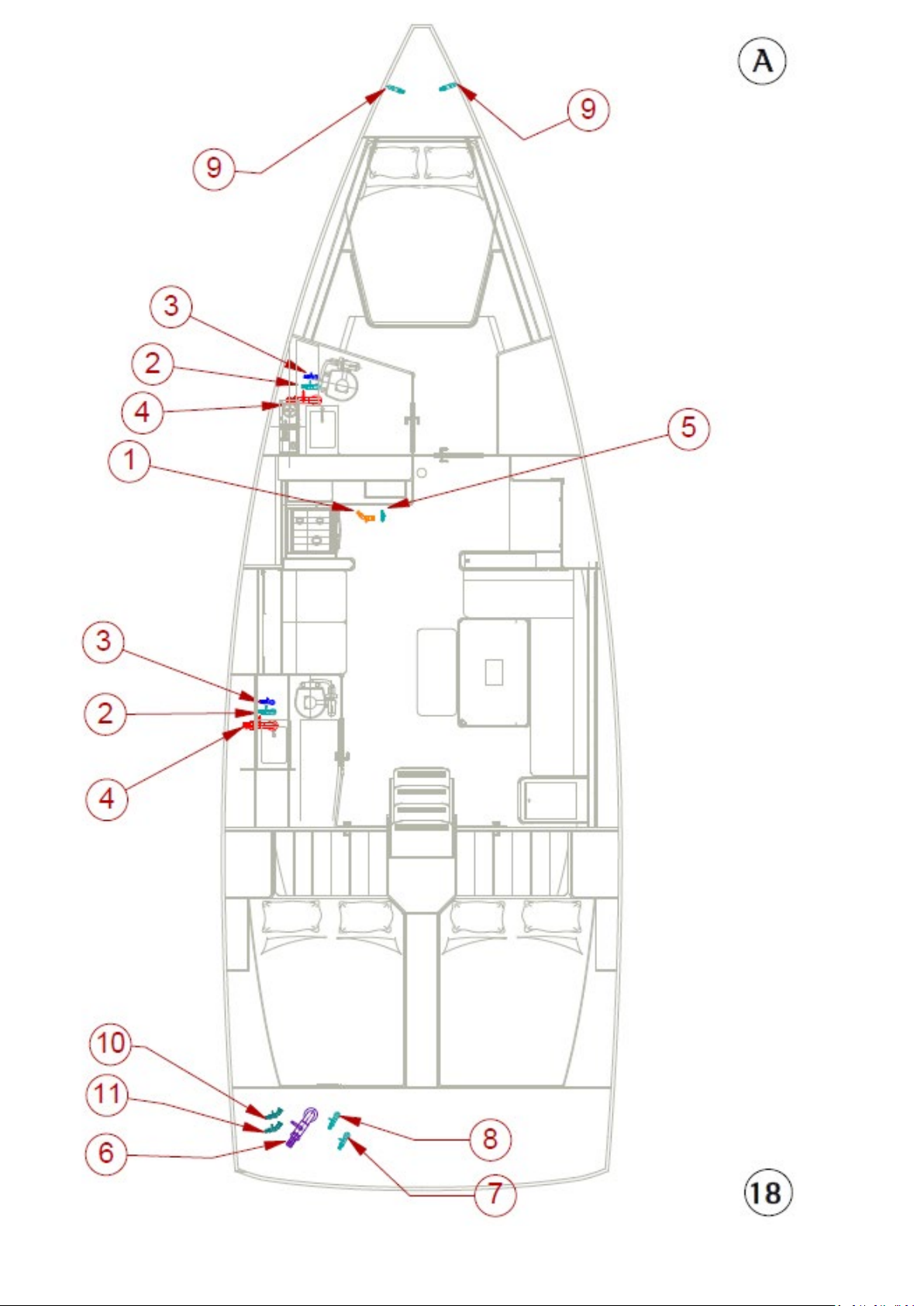
ENGLISH 26-02-2019 Page 80/92 DUFOUR 430 GRAND LARGE
Page 81
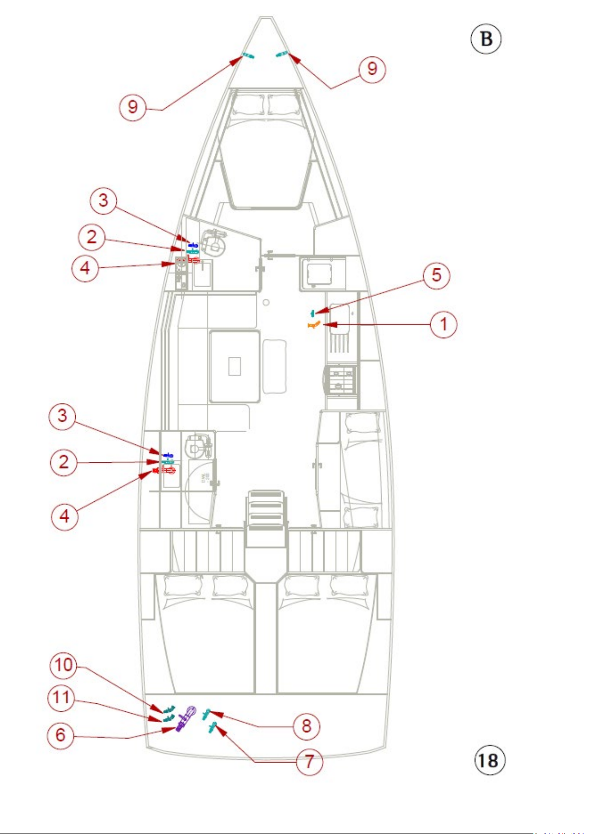
ENGLISH 26-02-2019 Page 81/92 DUFOUR 430 GRAND LARGE
Page 82
l
Description
1
Engine
2
Polyester frame
3
Sail Drive
4
Anode
5
Propeller
6
Foam insulation
7
Anti-siphon elbow
8
Waterlock silencer
9
Exhaust outlet
10
Bilge fan
11
Ventilation grilles
12
Starter battery
13
Isolator
14
Charge splitter
15
Engine control lever
16
Engine instruments
17
Seawater filter
19 Mechanical installation diagram
Labe
ENGLISH 26-02-2019 Page 82/92 DUFOUR 430 GRAND LARGE
Page 83
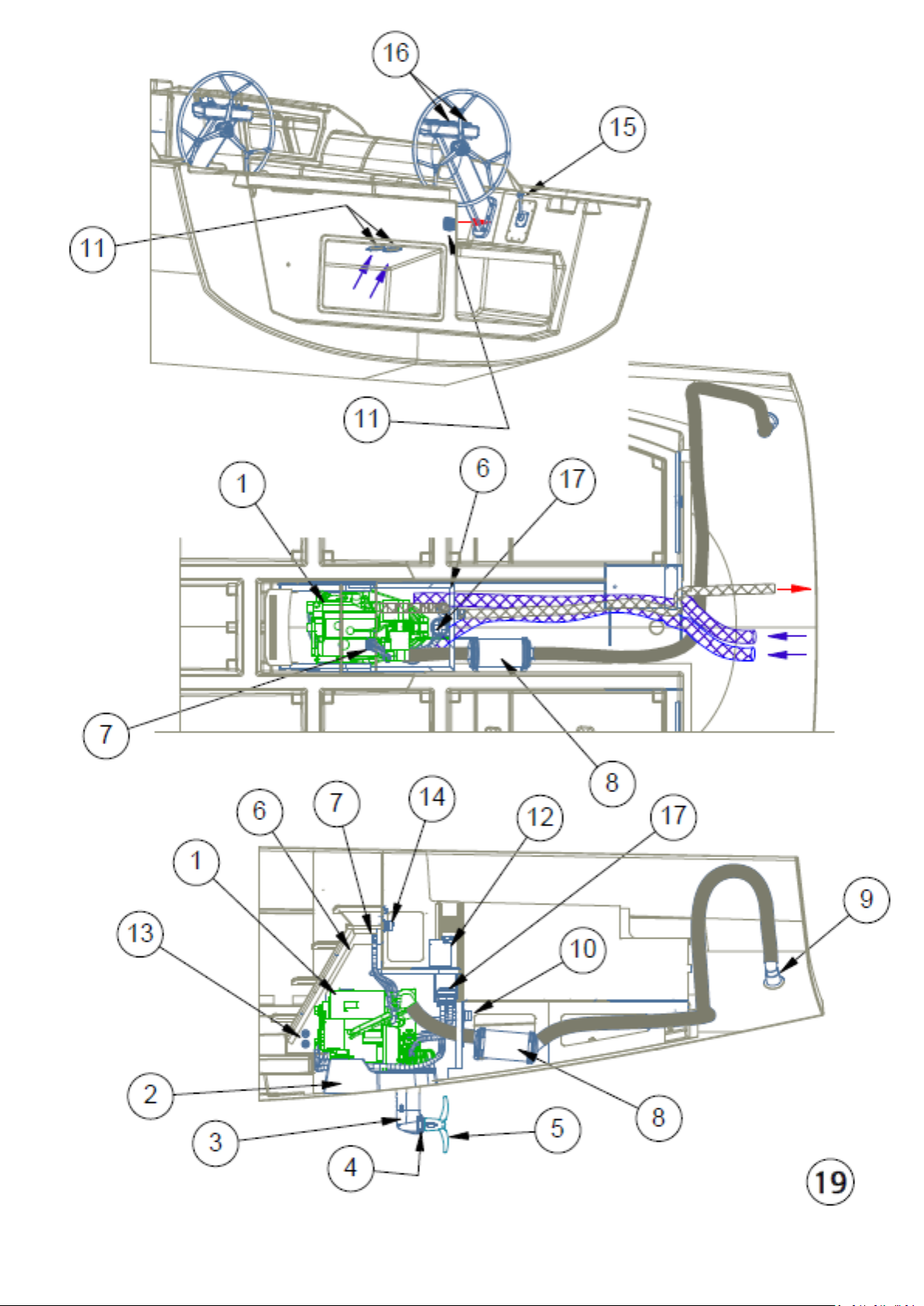
ENGLISH 26-02-2019 Page 83/92 DUFOUR 430 GRAND LARGE
Page 84
20 Gas system diagram
l
Description
2
Fuel shut-off valve
3
Overflow vent
4
Fuel deck plate
6
Fuel pre-filter
Labe
1 Diesel tank
5 Tank vent
ENGLISH 26-02-2019 Page 84/92 DUFOUR 430 GRAND LARGE
Page 85
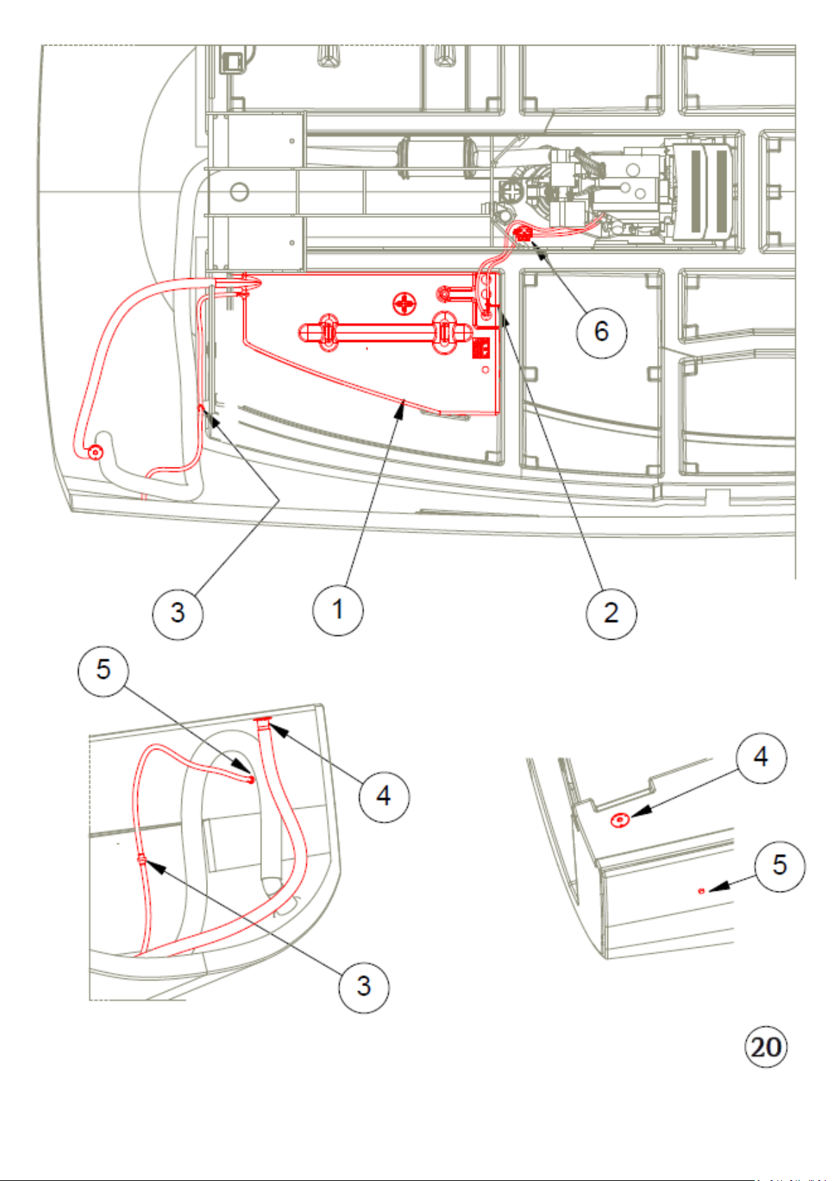
ENGLISH 26-02-2019 Page 85/92 DUFOUR 430 GRAND LARGE
Page 86
l
Description
1
3/4" cock and skin fitting
3
1-1/2" cock and skin fitting
4
20 mm Ø hose
5
38 mm Ø anti-odour hose
7
¾" chromed brass vent
8
Polyethylene holding tank, 50 L
9
Polyethylene holding tank, 45 L
X U-bend
21 Holding tank installation diagram
Labe
2 Black water deck plate Ø50
6 51 mm Ø anti-odour hose
ENGLISH 26-02-2019 Page 86/92 DUFOUR 430 GRAND LARGE
Page 87
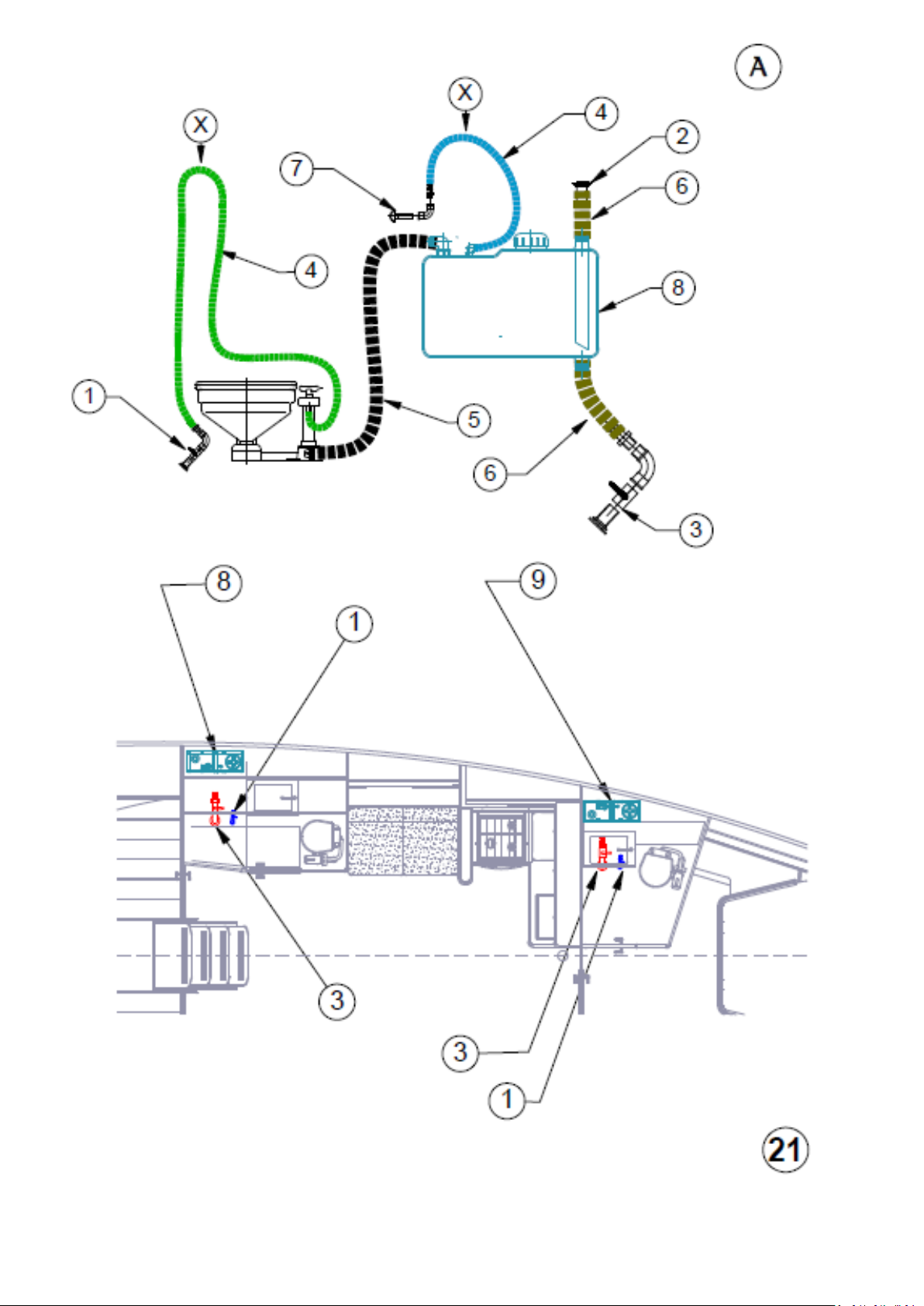
ENGLISH 26-02-2019 Page 87/92 DUFOUR 430 GRAND LARGE
Page 88
Label
.
Description
See red triangular marker
under deck-line
Midship beam:
4.30 m
Standard draft:
2.10 m
22 Lifting diagram
Displacement with maximum load: 12800 kg
ENGLISH 26-02-2019 Page 88/92 DUFOUR 430 GRAND LARGE
Page 89
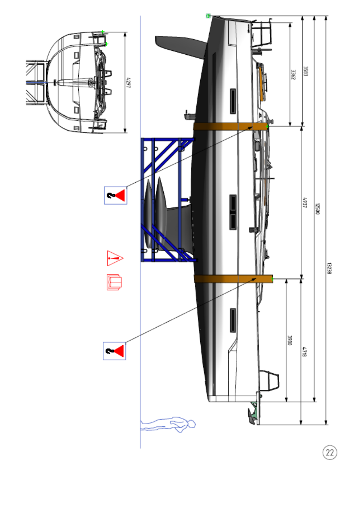
ENGLISH 26-02-2019 Page 89/92 DUFOUR 430 GRAND LARGE
Page 90
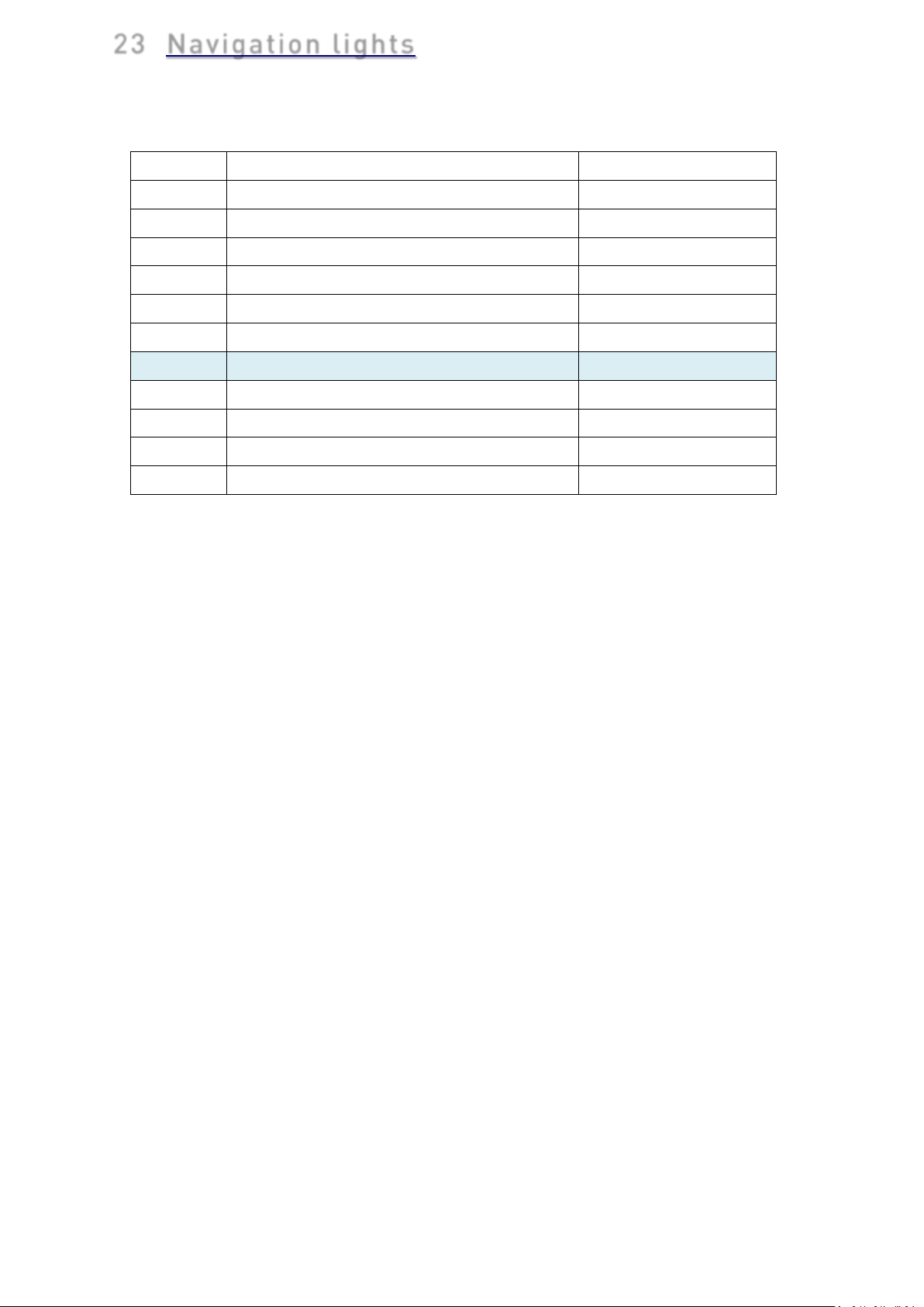
23 Navigation lights
Label
Function
Action
A
Under sail
1st push
B
Motor sailing
2nd push
C
Mooring
3nd push
Return Lights Off
4nd push
D Switch on 12V panel
Red / green bow lights
Range 2Nm
Stern light
Range 2Nm
Steaming light
Range 2Nm
Mooring light
Range 2Nm
ENGLISH 26-02-2019 Page 90/92 DUFOUR 430 GRAND LARGE
Page 91
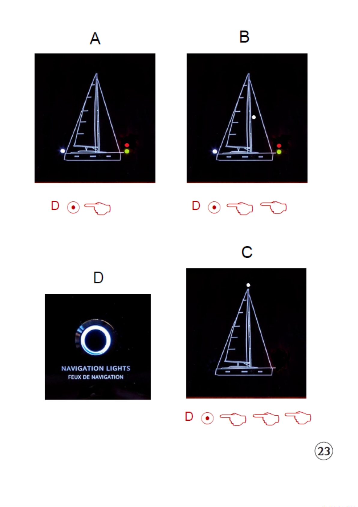
ENGLISH 26-02-2019 Page 91/92 DUFOUR 430 GRAND LARGE
Page 92

NOTES
ENGLISH 26-02-2019 Page 92/92 DUFOUR 430 GRAND LARGE
 Loading...