

Page 1
CAUTION!
This manual contains important information for the correct installation, operation and maintenance of the equipment
described herein. All persons involved in such installation, operation, and maintenance should be thoroughly familiar with
the contents. To safeguard against the possibility of personal injury or property damage, follow the recommendations and
instructions of this manual and keep it for further reference.
WARNING!
The equipment shown in this manual is intended for industrial use only and should not be used to lift, support, or otherwise
transport people unless authorized in writing by Duff-Norton.
Page 2

TABLE OF CONTENTS
PAGE
SECTION I
1-1
1-2
1-3
1-4
TABLE 1-4
TABLE 1-4-1
1-5
FIGURE 1-6
SECTION II
2-1
2-2
2-3
2-4
SECTION III
3-1
SECTION IV
4-1
4-2
4-3
4-4
4-5
GENERAL INFORMATION
General 3
Industrial Use Only 3
Factory Preparation 3
Specifications 3
6415 Series DC Actuator Specifications 3
6415 Series DC Super Pac Actuator Duty Cycle 3
Warranty and Warranty Repair 3
Dimensions and Specifications 4
INSTALLATION
Installation Procedures 5
Limit Switch Adjustment 5
Post-Installation Procedures 5
Potentiometer Adjustment 6
OPERATION
Operational Procedures 6
MAINTENANCE
Lubrication 7
Required Tools 7
General Procedures 7
Disassembly 7
Assembly 8
SECTION V
FIGURE 5-1
5-1
SECTION VI
6-1
FIGURE 6-1A
FIGURE 6-1B
6-2
FIGURE 6-2
6-3
ILLUSTRATED PARTS LIST
Exploded Illustration 6415 & 7415 AC Actuator 12
Parts List 13
TECHNICAL ILLUSTRATIONS
Brake Alignment 14
Brake Spring, Motor and Pinion Coupling Alignment 14
Brake Spring, Motor and Pinion Coupling Alignment 14
Limit Switch Wiring Diagram 15
Limit Switch Wiring Diagram, 6415 & 7415 Series AC Actuator 15
Limit Switch Assembly 15
Page 3

GENERAL INFORMATION
1-1. GENERAL
This manual provides instructions for the installation,
operation and maintenance of the Duff-Norton 6415 &
7415 Series AC actuator. It includes proper procedures
for the disassembly, cleaning, inspection, rebuilding and
assembly of the actuator. To ensure efficient, long,
satisfactory use of this unit, these instructions should be
followed closely.
1-2. INDUSTRIAL USE ONLY
The actuators described and illustrated in this manual
are intended for industrial use only and should not be
used to lift, support or otherwise transport people,
unless you have a written statement from Duff-Norton
Company which authorizes this actuator unit, as used in
your application, as suitable for moving people.
1-3. FACTORY PREPARATION
Each actuator is carefully assembled and tested at the
factory to ensure that the motor and the mechanical
components will function properly and that the actuator
will lift its rated load.
The brake is preset at the factory and no further
adjustment is required. With proper maintenance, this
brake prevents the actuator from self-lowering.
The actuator is pre-lubricated at the factory and thus
requires minimum maintenance.
Limit switches are checked at the factory for proper
functioning.
External wires are provided for customer
hookup. Wires are color coded as to direction of travel of
the actuator (see wiring diagram, Figure 6.2).
1-4. SPECIFICATIONS
TABLE 1-4.
SECTION 1
1-5. WARRANTY AND WARRANTY REPAIR
Subject to the conditions stated herein, Duff-Norton will
repair or replace, without charge, any parts proven to
Duff-Norton's satisfaction to have been defective in
material and workmanship. Claims must be made within
one year after date of shipment. Duff-Norton will not
repair or replace any parts that become inoperative
because of improper maintenance, eccentric loading,
overloading, chemical or abrasive action, excessive heat,
or other abuse.
Equipment and accessories not of Duff-Norton's
manufacture are warranted only to the extent that they
are warranted by their manufacturer, and only if the
claimed defect arose during normal use, applications
and service. Equipment which has been altered or
modified by anyone without Duff-Norton's authorization
is not warranted by Duff-Norton. EXCEPT AS STATED
HEREIN, DUFF-NORTON MAKES NO OTHER
WARRANTIES, EXPRESS OR IMPLIED, INCLUDING
WARRANTIES OF MERCHANTABILITY AND FITNESS
FOR A PARTICULAR PURPOSE.
If you have any questions concerning warranty
repair, please contact the Duff-Norton Company.
Authorization for return must be received from
the Duff-Norton Company before returning any
equipment for inspection or warranty repair.
Speed
(in/min)
Applied Standard Standard Standard Standard
Load 115 Volt 220 Volt 115 Volt 220 Volt
(lbs.) Motor Motor Motor Motor
(60 Hz) (50 Hz) (60 Hz) (50 Hz)
500 52 44 5.00 1.70
1000 51 42 5.50 1.70
1500 50 41 6.20 2.00
Amps
3
Page 4
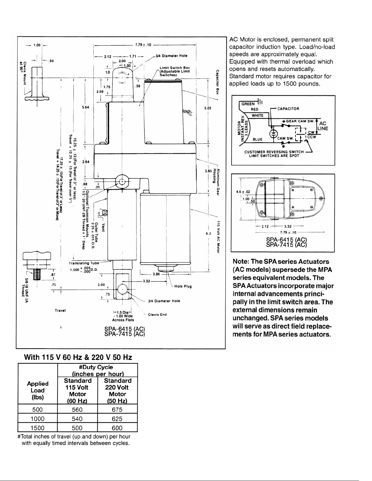
FIGURE 1-6. DIMENSIONS AND SPECIFICATIONS
WARNING:
1. Some actuator external surface temperatures may reach 230°F at or near
maximum allowable duty cycle.
2. Do not operate actuator before setting limit switches.
3. Position hooded vent to prevent moisture and dirt from entering actuator
(see instruction and maintenance sheet).
4. The actuator is not recommended for use in applications where it can be
jammed. Examples of jamming include overtraveling the limit switches and
jamming the nut and screw internally at the extreme ends of the stroke, or
driving the actuator against an immovable object and thus overloading the
actuator severely. Therefore consult Duff-Norton Engineering if jamming is
expected.
4
Page 5

INSTALLATION
2-1. INSTALLATION PROCEDURES
Use Figure 6-2 as a guide to properly attach the SPA
6415 & 7415 AC actuator to your power source.
2-2. LIMIT SWITCH ADJUSTMENT
CAUTION
Disconnect power before making any adjustments to the
limit switches.
IMPORTANT
Before attempting to set limit switch nuts by these
instructions, be certain that the red and blue motor leads
and the switch leads are connected properly per Figure
6-2. Unless leads are connected exactly as shown, the
following steps will be meaningless.
1.Setting Retracted Position
A. Do not install actuator in the intended
application at this time.
B. With nut retainer “A” installed in actuator
and the translating tube unstrained, operate
actuator toward retracted position until limit
switch nut “B” trips limit switch (see Figure 6-3).
NOTE
Translating tube may jam and rotate prior to tripping limit
switch.
SECTION II
extended centerline to centerline dimension
listed in Figure 1-6.
B. Remove nut restrainer “A” and rotate limit
switch nut “C” (see Figure 6-3) until it activates
the limit switch.
C. Replace nut restrainer “A”.
D. Install actuator in application and check the
unit's drift. Slight readjustment in switch
actuation may be attained by removing nut
restrainer “A” and (1) rotating limit switch nut
“B” to adjust retracted position or (2) rotating
limit switch nut “C” to adjust extended position
(1 notch of rotation = .05 in. of screw travel).
E. After adjusting limit switch nuts,
replace nut restrainer “A”. Operate the actuator
and readjust limit switch nuts as necessary to
achieve desired travel.
2-3. POST-INSTALLATION PROCEDURES
After actuator installation, position the air vent to prevent
moisture and dirt from entering the actuator. Vent can be
repositioned by loosening the set screw and rotating the
outer air tube into which the air vent is threaded. Spot drill
and re-tighten set screw.
If necessary, an elbow (1/8" female x 1/8" male
pipe thread) can be used for more effective positioning.
C. Rotate the translating tube by hand until
distance between the housing clevis hole
centerline and the translating tube clevis hole
centerline equals the desired closed height. This
centerline to centerline dimension is not to be
less than the retracted centerline to centerline
dimension listed in Figure 1-6. If the two clevis
end holes are not oriented as required, rotate the
translating tube no more than 1/2 turn in either
direction until they are properly oriented.
D. Install actuator in application and check drift.
Slight readjustment in switch actuation may be
attained by removing nut restrainer “A” and
rotating limit switch nut “B” (1 notch of
rotation = .05 in. of screw travel). Replace nut
restrainer, “A”.
2. Setting Extended Position
A.Restrain the translating tube against rotation
by hand. Operate the actuator, toward the
extended position, until the distance between
the housing clevis hole centerline and the
translating tube clevis hole centerline equals the
desired extended height. This centerline to
centerline dimension is not to exceed the
FOR UNITS WITH POTENTIOMETER
2-4. POTENTIOMETER INSTALLATION
1. Loosen pot locknut and remove from actuator.
2. For best accessibility, solder leads to pot at this time.
3. Limit switches should be set for extreme limits of travel
per instructions. Limit switch cam adjustments should be
made per paragraph 2 prior to potentiometer installation.
CAUTION
DO NOT ENGAGE POTENTIOMETER SHAFT GEAR
TEETH WITH PLASTIC WORM BEFORE READING
THE FOLLOWING PROCEDURE. F
ADHERE TO THE FOLLOWING PROCEDURE
COULD CAUSE DAMAGE TO THE
POTENTIOMETER.
4. Retract actuator translating tube until stopped by limit
switch.
5. a.
FOR TRAVELS UP TO 9
i. Turn pot shaft counterclockwise until
resistance between terminal SSand
CCCCWW
will be the pot’s full retracted position.
is approximately 100 ohms. This
””
(SINGLE TURN POT):
AILURE TO
5
Page 6

SECTION III
OPERATION
ii. Being careful not to turn the pot shaft, slide
it into engagement with the plastic worm and
tighten locknut.
iii. Re-check resistance. If necessary loosen
locknut slightly and twist pot to re-establish
100 ohm resistance. Pot does not have end
of travel stops, but has a 20˚ deadband
between the two ends of the resistive element.
No continuity will be measured to terminal
if the slider is in the deadband.
iv. Run actuator to full extension (do not let
tube rotate) until it is stopped by its limit
switch.
v. Check resistance between SSand
be sure the slider is still on the element and
the resistance is greater than 100 ohms. The
pot has enough rotation for 9.43 inches of
travel. (For strokes shorter than 9”, the
retracted resistance can be increased so that
pot adjustment is less critical.
b.
FOR TRAVELS GREATER THAN 9
CCCCWW
””
(MULTI-TURN POT):
i. Turn pot shaft counterclockwise until it
reaches its stop. Now turn shaft back
clockwise
ii. Without turning pot shaft, slide pot onto
engagement with the plastic worm and tighten
locknut.
iii. Starting
pot has enough rotation for 25” of actuator
travel.
6. With this set-up, potentiometer will have increasing
resistance from S to CCW (and decreasing resistance
from S to CW) as the actuator extends.
1
/4 turn.
1
/4 turn from the end, the 3-turn
to
3-1. OPERATIONAL PROCEDURES
This motor is an intermittent duty type motor. Since the
motor draws approximately the same amperage at no
load as at full rated load, it only takes 10 minutes of
cntinuous running, regardless of how light the load may
be, before the thermal overload relay cuts out. It then
takes about 10 minutes before the motor cools
sufficiently for the thermal relay to close. Make sure that
SS
the duty cycle to which the actuator is subjected is not
too severe for the motor.
Avoid using low voltage supply for the motor. All
wiring, switches etc. must be of sufficient capacity to
carry the required current.
The axis of the clevis pins should be parallel so
that the actuator can pivot without binding. The preset
brake will provide consistent braking for the actuator.
However, in the event the brake friction surfaces become
worn as indicated by excessive drift, the brake will
require rebuilding. To aid in rebuilding, a repair kit with
step by step instructions is available through Duff-Norton
Company under repair kit part number SK-6415-41. The
repair can be performed by the customer or by any
authorized repair station.
WARNING
This actuator is not recommended for use in applications
where it can be jammed. Examples of jamming include
overtraveling the limit switches and thus jamming the nut
and screw internally at the extreme ends of the stroke,
and driving the actuator against an immovable object
and thus severely overloading it. This actuator can jam a
limited number of times without damage. Therefore,
consult Duff-Norton Engineering if jamming is expected.
Do not operate actuator before setting limit
switches.
Some actuator external surface temperatures
may reach 230˚F at or near maximum allowable duty
cycle.
2-5. DIGITAL POSITION INDICATOR (DUFF-NORTON PART
NO. SK6300-4K)
The model SK6300-4K is a highly versatile, panel mount,
digital readout device that provides a very precise
indication of actuator position. It can be programmed to
display percentage, inches, or any other desired unit.
The indicator is self calibrating with no need for
measurements or calculations.
See detailed instructions with the SK6300-4K
indicator for installation and programming instructions.
Potentiometer terminal
indicator Common,
Signal Voltage Input.
CCCCWW
should be connected to
CCWW
to Excitation Voltage, and SSto
6
Page 7

MAINTENANCE
4-1. LUBRICATION
Duff-Norton recommends the use of the following
lubricant in conjunction with proper maintenance
procedures of this unit: Exxon Ronnex Extra Duty #1.
4-2. REQUIRED TOOLS
A bearing puller, press, soft jaw table clamp and
common hand tools are required for proper disassembly
and assembly.
4-3. GENERAL PROCEDURES
Duff-Norton recommends following these procedures
during disassembly and assembly:
1. Tag critical parts to facilitate reassembly.
2. Mark mating surfaces to ensure proper meshing.
3. Clean and lubricate parts as required.
4. All seals must be replaced at time of rebuild,
if damaged.
5. All screws, washers and other small common parts
must be replaced if mutilated in any way.
4-4. DISASSEMBLY
Disassemble the actuator as follows while referring to
Figure 5-1. Read instructions thoroughly before
disassembling.
NOTE
Disassembly should be accomplished on a clean cloth.
1. Clamp actuator housing (42) in vise (use soft
jaws). Unit should be in horizontal position with
outer tube (55) up.
2. Remove screws (1) from limit switch box
cover (11) and remove limit switch box cover
(11) and gasket (12).
3. Remove nut retainer (14).
NOTE
If unit has potentiometer assembly (26) and
potentiometer (26a) or gear (26b) is not damaged
proceed to Step 4.
a. Loosen nut (26c) and remove potentiometer
assembly from nut retainer (14).
b. Remove gear (26b) from potentiometer (26a).
Washer and nut do not have to be removed
from potentiometer (26a).
CAUTION
Take care not to damage potentiometer when removing
gear.
4. Remove screws (1) from capacitor box cover
(2) and remove cover (2) and gasket (3).
Remove insulation (4) from capacitor box.
5. Discharge capacitor (5). Disconnect motor (53) lead
wire terminals from capacitor (5). Remove
SECTION IV
capacitor from box.
6. Disconnect jumper wires (17 and 18) and motor (53) lead
wire terminals from switches (16). Remove jumper
wires (17 and 18) and pull motor (53) lead wires into
capacitor box.
7. Remove set screw (38) from housing (42).
8. Remove button head cap screws (7) and lock washer (8).
9. Lift cover (9) from housing (42) passing motor (53) lead
wires through hole in buttom of capacitor cavity in
cover (9). Slight tapping with soft hammer may be
necessary to overcome dowel pins (27).
10. Remove thrust washer (35) and thrust bearing (36)
from cover (9). Thrust washer (35) and thrust
bearing (36) may stay on spacer nut (37) in
housing (42) and can be removed in Step 18.
11. Remove limit switch shaft assembly, consisting of
limit switch shaft (22), limit switch nuts (23)
and worm (24), from cover (9). Allow limit
switch shaft (22) to drop out of flange bearing
(25). Tilt shaft assembly and remove from
cover (9).
NOTE
If limit switch nuts (23) or worm (24) do not have to be
replaced, proceed to Step 14.
12. Thread limit switchnuts (23) offof limit switch shaft (22)
13. Remove worm (24) from limit switch shaft (22).
NOTE
If switches (16), insulation (19) or limit switch bracket (21) do
not have to be replaced, proceed to Step 16.
14. Remove screws (20) and bracket (21) from cover (9).
15. Remove screws (15), switches (16) and insulation (19)
from bracket (21).
16. Press clevis end bushing (6) out of cover (9). If bushing
(6) is not damaged it should not be removed.
17. Remove bearing (28), bushing (34) and flange bearing
(25) from cover (9).
NOTE
Bushing (34) and flange bearing (25) should not be removed
unless they are damaged. Bearing (28) may stay on pinion
(29) and can be removed in Step 18.
18. Remove thrust washer (31) from intermediate pinion
shaft (32). Bearing (28) from pinion (29), thrust
washers (35) and thrust bearing (36) from
spacer nut (37) may have been removed in
Step 10.
19. Remove spring (61) from end of screw (62).
20. Remove intermediate cluster gear (33), intermediate
pinion shaft (32) and thrust washer (31).
7
Page 8

21. Remove socket head cap screws (45), lock washers
(46) and disassemble motor (53) from housing
(42).
WARNING
Care must be taken not to damage motor lead wires.
22. Remove “O”-Ring (52) and rubber grommet (50).
23. Disassemble outer tube (55) and slip off over
translating tube and clevis (66).
24. Remove air vent (58), wiper scraper (60) and guide
bushing (59) from outer tube (55).
NOTE
If wiper scraper or guide bushing are not damaged they
should not be removed.
25. Remove set screw (68) from spacer nut (37) and
disassemble spacer nut (37) from screw (62) by
clamping screw (62) between soft jawed vise.
WARNING
Care must be taken not to damage bearing journal of
spacer nut (37).
26. Remove output gear (39), key (40), thrust washers
(35), thrust bearing (36), and gear spacer (43).
27. Remove screw (62), translating tube and
clevis (66) and nut assembly (64).
28. Remove washer (44) from screw (62).
29. Thread screw (62) into the translating tube until the
screw bottoms out and cannot rotate farther, or
until the screw thread becomes disengaged
from the lifting nut thread (64).
30. Drive the four pins (65) just far enough into the
lifting nut (64) to clear the translating tube wall;
then remove the translating tube from the nut.
31. Remove the lifting screw (62) from the lifting nut (64).
32. Remove the four pins (65) by pressing each one the
rest of the way through the lifting nut wall.
33. Remove the stop pin (63) from the lifting screw (62)
if necessary.
34. Removing the brake (49) .(Required only if drift is
excessive. If brake removal is not necessary,
proceed to Step 35).
a. Push on the pinion(29) and coupling (47) until
it slips back enough to make the spring (49)
tang accessible.
b. Remove the spring (49) by grabbing the tang
with pliers and twisting out. (Spring must now
be replaced and can no longer be used.)
c. Remove the brake insert (51). Remove
retaining ring (48) from input pinion (29). Input
pinion (29) and bearing (30) can now be
removed from housing (42).
d. The brake inset (51) has straight knurls on its
O.D. which prevent it from rotating. Therefore,
the insert can only be removed by pulling
straight out.
e. One method of removing the insert (51) is to
use a blind hole bearing puller. This tool
expands into the internal spring cavity and pulls
against the lip of the insert (51).
35. If coupling (47) on motor (53) shaft must be
replaced, remove retaining ring (48) from motor
(53) shaft and remove coupling (47).
DISASSEMBLY IS COMPLETE.
4-5. ASSEMBLY
Assemble the actuator as follows while referring to
Figure 5-1. Read instructions thoroughly before
assembling.
NOTE
Be sure all components are clean and dry before
assembling.
1. Assemble coupling (47) on motor shaft, then install
retaining ring (48) on motor shaft.
2. Press bearing (30) on input pinion (29) (press load
should be applied to inner race of bearing to
avoid damage to bearing).
3. Press bushing (34) into housing (42).
4. Install input pinion (29) and bearing assembly (30) in
housing (42) (press load should be applied to
outer ring of bearing to prevent damage to
bearing).
5. Assemble coupling (47) on input pinion (29) and
install retaining ring (48).
6. Brake Assembly
a. Grease O.D. of spring (49) and pocket of
insert (51) (chamfered end) with Aeroshell #6
grease.
CAUTION
When using replacement parts, make sure you have
correct spring. (Part No. SK-6415-18). Red spring
designates DC unit. If your replacement spring is red,
contact your local distributor or the Duff-Norton Factory
for immediate replacement.
b. Install spring (49) into insert (51) pocket
(chamfered end).
c. Align pinion coupling (47) and spring (49) as
shown in Figure 6-1A and press insert (51) and
spring (49) assembly into housing (42)
8
(alignment must be as shown in Figure 6-1A).
Page 9

7. Press bushing (34), bushing (6) and flange bearing
(25) into cover (9).
8. Assembly of Limit Switch Components (refer to
Figure 6-3).
a. Assemble insulation (19), limit switch (16)
and screw (15) on limit switch bracket (21).
NOTE
Limit switch (16) leads should face each other. Insulation
(19) should be folded up and behind common terminal of
switches (16). See Figure 6-3.
b. Assemble limit switch nuts (23) on limit
switch shaft (22) (care should be taken not to
cross-thread nuts). Nut hubs should be facing
away from each other. See Figure 6-3.
c. Assemble worm (24) on limit switch shaft
(22). Unthreaded hub on worm should be away
from limit switch shaft (22) threads.
See Figure 6-3.
9. Assembly of Limit Switch Components in cover. Refer
to Figures 6-2 and 6-3.
NOTE
Cover (9) should be in a soft-jaw vise with limit switch
box cover up.
10. Assemble limit switch bracket (21), insulation (19)
and switch (16) assembly into cover (9) with
screws (20).
11.Assemble limit switch shaft (22), limit switch nuts
(23) and worm (24) assembly into cover (9).
Tilt shaft and insert into I.D. of bushing (34).
Then straighten and assemble shaft into flange
bearing (25).
NOTE
Worm (24) should be facing up toward flange bearing
(25). See Figure 6-3 (shaft will be loose in cover).
12. Attach red terminal wire (17) to common terminal of
left side switch (16). Attach blue terminal wire
(18) to common terminal of right side switch
(16). Feed ends of terminal wires (17) and (18)
through 5/8" dia. hole into cover (9) capacitor
box.
13. Press guide bushing (59) and wiper scraper seal (60)
into outer tube (55). (Scraper part of scraper
seal should be facing outward away from guide
bushing.)
14. Install the stop pin (63) in the end of the lifting screw
(62), taking care to center the pin in the screw.
15. Screw the lifting nut (64) on to the lifting screw (62)
with the flange end away from the stop pin (63).
16. Fill the translating tube (66) approximately 1/2 to 3/4
full with Duboise M.P.G. grease (no
substitutes).
17. Slide the translating tube over the lifting screw (66)
and on to the lifting nut (64), lining the four
holes in the translating tube up with the four
holes in the lifting nut (64). Install pins (65)
flush with translating tube O.D.
18. Assemble washer (44) and gear spacer (43) on screw
(62). Install key (40) in key groove of screw.
19. Clamp sides of housing (42) in vise (use soft jaws
with input pinion up).
20. Install screw (62), gear spacer (43), washer (44),
translating tube (66), and tube nut (64)
assembly into housing (42) through bushing
(34).
21. Apply a generous amount of Aeroshell #6 grease (no
substitutes) to thrust washers (35) and thrust
bearing (36) and assemble over gear spacer
(37).
22. Aligning keyway in output gear (39) with key (40) in
screw (62), assemble output gear (39) on screw
(counter-bore in gear facing up away from
thrust bearing).
23. Clamp screw (62) between soft jawed vise. Thread
spacer nut (37) on screw (62) and tighten
against output gear (39). Spacer nut flange
should be in counterbore of output gear. Do not
grip on bearing journal of spacer nut when
tightening spacer nut.
24. Check alignment of tapped holes in spacer nut (37)
with holes in output gear (39). Use two 9/64
dia. pins approximately 11/2" long. One pin
should drop into hole in output gear (39). If pin
does not drop into hole, tighten or loosen
spacer nut until hole is aligned and one pin
drops into hole. (Note: spacer nut should not be
rotated more than 221/2 before pin drops into
hole in gear.) It is preferable to tighten spacer
nut down instead of loosening.
25. Remove pin from aligned hole. Install half dog set
screw (68) and tighten half dog point into hole
in output gear (39). Remove remaining pin and
proceed with assembly. Note: One hole must be
in alignment to have proper assembly.
26. Lightly grease O.D. of translating tube (66) with
Duboise M.P.G. grease (no substitutes) and
assemble outer tube (55) assembly over
translating tube (66) and thread into housing
(42) (a sealing compound such as NonHardening Permatex 2 should be used on
9
Page 10

threads).
27. Insert intermediate pinion shaft (32) in housing (42)
and place thrust washer (31) over shaft (32).
Assemble intermediate cluster gear (33) on shaft
and place thrust washer (31) on top.
28. Assemble bearing (28) on input pinion (29) (press on
inner bearing ring to prevent damage to
bearing).
29. Pack housing (42) gear box cavity with Aeroshell #6
grease (no substitutes).
30. Assembly of Motor (53) to Housing (42)
a. Note location of flat on input pinion by
marking spot on the housing. See Figure 6-1B.
b. Insert grommet (50) on input pinion (29)
between coupling (47) posts and install “O”Ring (52) in cavity of insert (51).
c. Pack cavity with Aeroshell #6 grease.
d. If hole plug (54) is in rear end of motor,
remove.
e. Feed motor (53) lead wires through hole in
housing (42) lining up couplings (47) on input
pinion (29) and motor (53) shaft. (Alignment is
critical at this point. See Figure 6-1B.)
NOTE
If unit has potentiometer assembly (26) and gear (26b) does
not have to be replaced or if unit has no potentiometer
feature, proceed to Step 35.
34. Potentiometer Assembly (26)
a. If nut and washer were removed from
potentiometer, assemble washer (26d) and nut
(26c) on potentiometer (26a). Nut (26c) should
not be tightened on potentiometer (26a) face.
b. Assemble gear (26b) on potentiometer (26a)
shaft.
NOTE
Gear should be assembled with a very light press. See
sketch for required dimension of gear on potentiometer. Take
care not to damage potentiometer.
35. Assembly of Cover (9)
a. Feed motor (53) lead wires into capacitor box
cover (9). Care should be taken not to damage
lead wires. Assemble cover on housing (42),
aligning dowel pins (27) with bore in
NOTE
Input pinion (29) and motor (53) shaft flats are opposite
each other.
f. Assemble motor (53) into housing (42) . Before
assembling lock washers (46) and socket head
screws (45), hold motor firmly in place and, with
a screwdriver, turn motor shaft by using
screwdriver slot in end of motor shaft.
NOTE
Before turning motor shaft, make sure pinion shaft has
not been pushed out. It may be necessary to hold pinion
shaft down while turning motor shaft. If couplings are
properly installed, the motor can be turned freely in both
directions. If motor shaft will not turn, this is an
indication that couplings are not properly aligned and
assembly should be corrected.
g. Install lock washers (46) and socket head
screws (45).
31. Insert dowel pins (27) in housing (42) and place
gasket (41) in place over dowel pins (27).
32. Install air vent (58) in outer tube (55) ( it may be
necessary to back outer tube out in order to
install air vent or to have vent in a more
desireable position). Spot drill tube and install
set screw (33) to hold tube in place.
33. Install spring (61) into end of screw (62).
cover and flats of limit switch shaft (22) with bore
and slot in end of screw (62).
NOTE
Limit switch shaft should be able to spring up when a light
pressure with finger is applied downward on limit switch nut
and removed.
b. Install lock washers (8) and button head cap
screws (7).
c. Feed motor lead wires (red and blue small
terminal ends only) into cover switch box through
5/8” diameter hole. Install terminal of red lead wire
on normally closed terminal of left side of switch.
Install terminal of blue lead wire on normally closed
terminal of right side of switch. (Wires going to
switches should be same color.) It may be necessary
10
Page 11

to install terminals on switch terminals tabs with
needle-nose pliers and care should be taken not to
damage terminal tab or switch (see Figure 6-3).
d. Feed terminal wires, (17) red, (18) blue, fuse
jumper wire, and motor lead through 1/2"
tapped hole in cover capacitor box outside of
cover.
e. Moving wires out of the way, insert capacitor (5)
into box (termials up) and attach motor lead wire
(large connectors) to capacitor terminals. (Red on
one pair of capacitor terminals and blue on the other
pair of capacitor terminals.)
f. Insert insulation (4) and assemble gasket (3)
and cover (2) with screws (1).
g. Adjust actuator limit switch settings per
instructions in paragraph 2-2.
h. If actuator has potentiometer, refer to
position indicator installation and calibration
instructions in Paragraph 2-4.
I. Attach gasket (12) and cover (11) with screws (1).
ASSEMBLY IS NOW COMPLETE.
11
Page 12

Page 13

SECTION V
PARTS LIST FOR FIGURE 5-1
5-1. PARTS LIST
PARTS LIST FOR DUFF-NORTON ACTUATOR, 6415 & 7415 SERIES AC ACTUATOR
IInnddeexx
NNoo..
Screw
1
Cover
2
Gasket
3
Insulation
4
Capacitor – 115 V
5
Capacitor – 220 V
Bushing
6
Button Head Cap Screw
7
Lock Washer
8
Cover
9
Tapered Closure
10
Switch Cover
11
Gasket
12
Instruction Decal
13
Nut Restrainer
14
Screw
15
Switch
16
Jumper Wire (Red)
17
Jumper Wire (Blue)
18
Insulation
19
Screw
20
Limit Switch Bracket
21
Limit Switch Shaft
22
LImit Switch Nut
23
Worm
24
Flange Bearing
25
Potentiometer Assembly
26
Potentiometer
26a
Gear
26b
Nut
26c
Lock Washer
26d
Dowel Pin
27
Bearing
28
Input Pinion
29
Bearing
30
Thrust Washer
31
Intermediate Pinion Shaft
32
Intermediate Cluster Gear
33
Bushing
34
Thrust Washer
35
Thrust Bearing
36
PPaarrtt NNaammee
QQttyy..
RReeqq.. PPaarrtt NNoo..
H-2979
8
SK-6415-38
1
SK-6415-37
1
SK-6415-47
1
SK-6405-7-6
1
SK-6405-7-8
1
SK-6415-96
1
H-2986
5
S-42-9
5
SK-6415-134
1
SK-6000-46
1
SK-6415-36
1
SK-6415-35
1
SK-6905-15
1
SK-6415-136
1
H-2984
4
SK-6415-131
2
SK-6415-32-1
1
SK-6415-32-2
1
SK-6415-132
2
H-2979
2
SK-6415-137
1
SK-6415-135
1
SK-6425-9
2
SK-6905-3
1
SK-6425-11
1
††
1
††
1
SK-6415-62
1
furnished with
1
26a
1
H-5391
2
SK-6415-5
1
SK-6415-3
1
SK-2374-5
1
255K14
2
SK-6415-9
1
SK-6415-4
1
SK-6415-11
2
255K10
4
511K11
2
IInnddeexx
NNoo..
Spacer Nut
37
Set Screw
38
Output Gear
39
Woodruff Key
40
Gasket
41
Housing
42
Gear Spacer
43
Washer
44
Socket Head Cap Screw
45
Lock Washer
46
Coupling
47
Retaining Ring
48
Spring
49
Rubber Grommet
50
Insert
51
“O”-Ring
52
Motor – 115 V
53
Motor – 220 V
Hole Plug
54
Outer Tube
55
Warning Decal
56
Actuator Deal
57
Air Vent
58
Guide Bushing
59
Wiper Scraper
60
Spring
61
Screw
62
Stop Pin
63
Nut
64
Pin
65
Translating Tube & Clevis
66
Half Dog Set Screw
68
PPaarrtt NNaammee
QQttyy..
RReeqq.. PPaarrtt NNoo..
1
SK-6415-17
1
H-2594
1
SK-6415-92
1
S-23-12
1
SK-6415-7
1
SK-6415-1
1
SK-6415-91
1
H-4011
3
S-49-94
3
H-4081-P
2
SK-6415-20
2
SK-2374-8
1
SK-6415-18
1
SK-6415-29
1
SK-6415-21
1
X-6477-72
1
SK-6415-19
1
Sk-6515-96
1
1
SK-6415-111**
1
SK-6415-59
1
SK-6415-67
1
SK-2015-218
1
SK-6415-23
1
SK-6415-16
1
JF-343-3
1
SK-6415-113*
1
H-5122
1
SK-6415-15
4
H-5164
1
SK-6415-109-A*
1
H-2612
**DDeennootteess ddaasshh nnuummbbeerr iiss eeqquuaall ttoo ttrraavveell
**** DDeennootteess ddaasshh nnuummbbeerr iiss 33 ffoorr ttrraavveell.. 33 iinncchheess oorr lleessss.. OOtthheerrwwiissee ddeennootteess ddaasshh nnuummbbeerr iiss eeqquuaall ttoo ttrraavveell iinn iinncchheess..
††
OPTIONAL
Ohms/Inch Potentiometer
Travel Potentiometer (26a) Ohms Change with gear (26)
9" or less SK-3275-24 5000 530 SK6415-70-10A
over 9" SK6200-18 5000 167 SK6415-70-5A
13
Page 14

6-1. BRAKE ALIGNMENT
SECTION VI
TECHNICAL ILLUSTRATIONS
Figure 6-1A. Brake, Spring,
Motor and Pinion Coupling
Alignment
6-2. LIMIT SWITCH WIRING DIAGRAM
Figure 6-1B. Brake Spring,
Motor and Pinion Coupling
Alignment
FIGURE 6-2. LIMIT SWITCH WIRING DIAGRAM, 6415 &
7415 SERIES AC ACTUATOR
14
Page 15

6-3. LIMIT SWITCH ASSEMBLY
**MOTOR LEAD WIRE (RED) SMALL TERMINAL
* MOTOR LEAD WIRE (BLUE) SMALL TERMINAL
FIGURE 6-3. LIMIT SWITCH ASSEMBLY,
6415 & 7415 SERIES AC ACTUATOR
15
Page 16

P.O. Box 7010 • Charlotte, NC 28241-7010
Phone: (800) 477-5002 • (704) 588-4610
Fax: (704) 588-1994
Email: duffnorton@cmworks.com
www.duffnorton.com
© Yale Industrial Products, Inc., Duff-Norton Division, 2006
All rights reserved by Yale Industrial Products, Inc., Duff-Norton Division.
May not be copied in whole or in part.
Printed in the USA
ECO 98865
1M\SK6415-200\1006
 Loading...