


Publication Part No. SK-2373-R
 CAUTION
This manual contains important information for the correct installation, operation and maintenance of the |
|
equipment described herein. All persons involved in such installation, operation, and maintenance should be |
|
thoroughly familiar with the contents. To safeguard against the possibility of personal injury or property |
|
damage, follow the recommendations and instructions of this manual and keep it for further reference. |
® |
|
 WARNING
The equipment shown in this manual is intended for industrial use only and should not be used to lift, support, or otherwise transport people.
|
Contents |
|
Section I |
General Information ................................................................................................................. |
3 |
1-1. |
General...................................................................................................................................... |
3 |
1-2. |
Applications .............................................................................................................................. |
3 |
1-3. |
Table of Specifications ............................................................................................................. |
3 |
1-4. |
Dimensions ............................................................................................................................... |
4 |
Table 3. |
Upright Models......................................................................................................................... |
4 |
Table 4. |
Inverted Models ........................................................................................................................ |
5 |
1-5. |
Important Precautions ............................................................................................................... |
6 |
1-6. |
Warranty and Warranty Repair ................................................................................................. |
6 |
Section II |
Maintenance.............................................................................................................................. |
7 |
2-1. |
Lubrication ............................................................................................................................... |
7 |
2-2. |
Rebuild Procedure .................................................................................................................... |
7 |
2-3. |
Required Tools .......................................................................................................................... |
7 |
2-4. |
Disassembly.............................................................................................................................. |
7 |
Table 2-1. |
Dimensions Ball Nut Storage Arbor ......................................................................................... |
8 |
Figure 2-2. |
Ball Nut Storage Arbor ............................................................................................................. |
9 |
2-5. |
Cleaning .................................................................................................................................... |
9 |
2-6. |
Inspection ................................................................................................................................. |
9 |
2-7. |
Assembly .................................................................................................................................. |
9 |
Figure 2-3. |
Expansion Plug Replacement ................................................................................................. |
11 |
Section III |
Illustrated Parts List ................................................................................................................ |
12 |
3-1. |
General.................................................................................................................................... |
12 |
3-2. |
Parts List for 2800 and 9800 Series Rotating Ball Screw Actuators ...................................... |
12 |
Figure 3-1. |
Exploded Illustration 2800 and 9800 Series Ball Screw Actuators ........................................ |
13 |
2
Section I
General Information
1-1. General
This manual contains maintenance instructions for Duff-Norton® rotating ball screw actuators. It describes and details procedures for installation, disassembly, cleaning, inspection, and assembly of these actuators.
1-2. Applications
Industrial Use Only The actuators described and illustrated in this manual are intended for industrial use only and should not be used to lift, support or otherwise transport people unless you have a written statement from Duff-Norton Company which authorizes the specific actuator unit, as used in your application, as suitable for moving people.
These actuators are intended for a clean, non-
1-3. Table of Specifications
corrosive environment with ambient temperatures ranging from -20 to 200 ° F. If your environment is dirty and/or contains abrasive particles it is important to protect the screw with a boot. If your atmosphere is corrosive it is important to specify a noncorrosive material or finish. Duff-Norton can provide stainless steel, nickel plated or epoxy coated actuators. If your duty is high or your use severe, more frequent lubrication should be employed. DuffNorton publishes a Mechanical Actuator Design Guide, Catalog No. 2003, which you may find helpful in the selection and application of mechanical actuators. If you need additional help, please contact Duff-Norton at (800) 477-5002.
Standard Actuator |
Upright |
UM28632 |
KUM2803/UM9803 |
KUM28004/UM98004 |
KUM2804/UM9804 |
UM9806 |
UM98061 |
UM9811 |
UM98111 |
AUM9821 |
UM9826 |
UM2861 |
Model Numbers |
Inverted |
DM28632 |
KDM28031/UM98031 |
KDM28004/UM98004 |
KDM2804/DM98004 |
DM9806 |
DM98061 |
DM9811 |
DM98111 |
ADM9821 |
DM9826 |
DM2861 |
Special Actuator |
Upright |
UM38632 |
UM3803/UM9803 |
UM38004/UM98004 |
UM3804/UM108004 |
UM10806 |
UM10806 |
UM10811 |
UM10811 |
UM10821 |
UM10826 |
UM3861 |
Model Numbers |
Inverted |
DM32632 |
DM3803/UM9803 |
DM38004/UM98004 |
DM3804/DM108004 |
DM10806 |
DM10806 |
DM10811 |
DM10811 |
DM10821 |
DM10826 |
DM3861 |
Capacity, Tons |
|
1/2 |
2 |
2 |
3 |
5 |
5 |
10 |
10 |
20 |
25 |
50 |
Diameter of |
|
5/8 |
1 |
1 |
1 11/64 |
1 1/2 |
1 1/2 |
1 1/2 |
1 1/2 |
2 1/4 |
3 |
4 |
Lifting Screw (inches) |
.200 Lead |
.250 Lead |
1.000 Lead |
.413 Lead |
.474 Lead |
1.000 Lead |
.474 Lead |
1.000 Lead |
.500 Lead |
.660 Lead |
1.000 Lead |
|
Base Size (inches) |
|
2 1/4 x 4 |
3 1/2 x 7** |
3 1/2 x 7 |
3 1/2 x 7 |
6 x 8 |
6 x 8 |
7 1/2 x 8 3/4 |
7 1/2 x 8 3/4 |
8 1/4 x 11 |
10 1/4 x 13 3/4 |
9 3/4 x 19 3/4 |
|
Std Ratio |
5:1 |
6:1 |
6:1 |
6:1 |
6:1 |
6:1 |
8:1 |
8:1 |
8:1 |
10 2/3:1 |
10 2/3:1 |
Worm Gear Ratios |
Optional |
20:1 |
12:1 |
24:1 |
12:1 |
24:1 |
24:1 |
24:1 |
24:1 |
24:1 |
32:1 |
32:1 |
|
Optional |
— |
24:1 |
— |
24:1 |
— |
— |
— |
— |
— |
— |
— |
|
Std Ratio |
25 |
24 |
6 |
14.526 |
12.667 |
6 |
16.888 |
8 |
16 |
16.16 |
10.66 |
Turns of Worm |
Optional |
100 |
48 |
24 |
29.052 |
50.667 |
24 |
50.667 |
24 |
48 |
48.48 |
32 |
For 1˝ Raise |
Optional |
— |
96 |
— |
58.104 |
— |
— |
— |
— |
— |
— |
— |
|
Std Ratio |
1/3 |
2 |
2 |
2 |
4 |
4 |
5 |
5 |
5 |
8 |
15 |
Maximum H.P. |
Optional |
1/6 |
3/4 |
1/2 |
3/4 |
3/4 |
3/4 |
1 1/2 |
1 1/2 |
1 1/2 |
2 1/2 |
6 |
Per Actuator |
Optional |
— |
1/2 |
— |
1/2 |
— |
— |
— |
— |
— |
— |
— |
Starting Torque |
Std Ratio |
10.5 |
50 |
180 |
110 |
220 |
500 |
350 |
800 |
700 |
925 |
2,700 |
at Full Load |
Optional |
5.0 |
30 |
80 |
68 |
90 |
206 |
175 |
400 |
325 |
475 |
1,500 |
(lb-ins) |
Optional |
— |
25 |
— |
50 |
— |
— |
— |
— |
— |
— |
— |
Running Torque |
Std Ratio |
9.5 |
45 |
160 |
100 |
180 |
410 |
300 |
700 |
650 |
825 |
2,200 |
at Full Load |
Optional |
4.5 |
25 |
70 |
60 |
80 |
183 |
150 |
290 |
300 |
425 |
1,200 |
(lb-ins) |
Optional |
— |
20 |
— |
45 |
— |
— |
— |
— |
— |
— |
— |
|
Std Ratio |
65 |
59 |
59 |
59 |
70 |
70 |
65 |
65 |
61 |
60 |
55 |
Actuator Efficiency |
Optional |
38 |
44 |
33 |
44 |
39 |
39 |
42 |
42 |
44 |
39 |
33 |
Rating (%) |
Optional |
— |
33 |
— |
33 |
— |
— |
— |
— |
— |
— |
— |
Weight with Base |
|
2.75 |
20 |
20 |
21 |
40 |
40 |
50 |
50 |
115 |
235 |
520 |
Raise of 6˝ (lbs) |
|
|||||||||||
|
|
|
|
|
|
|
|
|
|
|
|
|
Weight for Each |
|
0.10 |
0.3 |
0.3 |
0.4 |
0.9 |
0.9 |
0.9 |
0.9 |
1.5 |
2.9 |
5.0 |
Additional 1˝ of |
|
|||||||||||
Raise (lbs) |
|
|
|
|
|
|
|
|
|
|
|
|
Hold-Back Torque |
Std Ratio |
1 |
2 |
2 |
7 |
8 |
8 |
11 |
11 |
24 |
24 |
92 |
at Rated Load |
Optional |
0.5 |
1 |
0.5 |
2 |
0.5 |
0.5 |
0.5 |
0.5 |
2 |
2 |
33 |
(lb-ft) |
Optional |
— |
0.5 |
— |
0.5 |
— |
— |
— |
— |
— |
— |
— |
Note: Hold back torque is restraining torque at the worm shaft, to keep load from running down. |
|
|
||||||||||
*Dimensionally same as Model 2803 |
† Dimensionally same as Model 9806 |
|
|
|
|
|
||||||
‡ Dimensionally same as Model 9811 |
** 9803 Base is 4 1/8˝ x 6˝ |
|
|
|
|
|
|
|||||
∆ Prefix for these model numbers is KUM for upright units and KDM for inverted units.
3
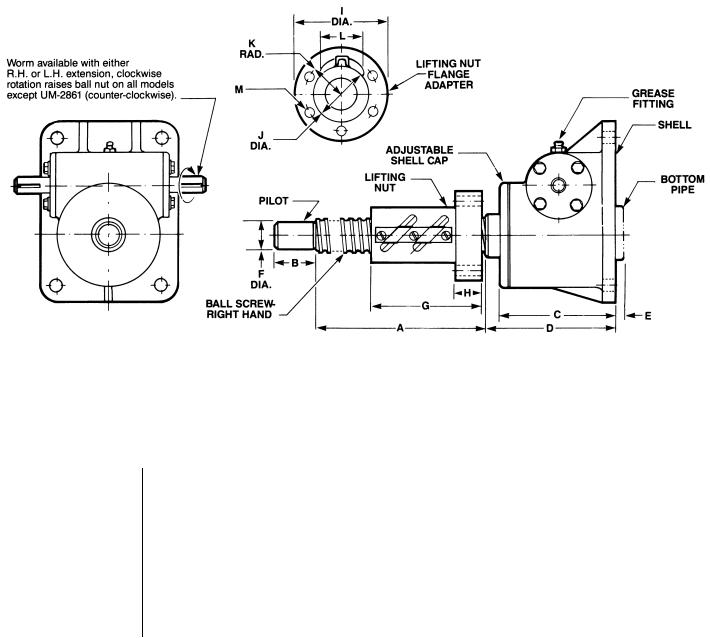
1-4. Dimensions
Note: Ball nut must be kept from rotating to prevent it from self-lowering.
Worm and gear set is not self-locking. Use brake on worm shaft or motor.
Housing dimensions and base configurations vary.
Table 3. |
Upright Models |
|
|
|
|
|
|
|
|
|
|
|
|
|
|||
|
|
Drawing |
|
|
|
|
|
|
|
|
|
|
|
|
|
|
|
Model Number |
Rating |
Ref. |
A |
|
B |
C |
D |
E |
F |
G |
H |
|
I |
J |
K |
L |
M |
UM-28632 |
1/2 TON |
28631 |
RAISE + 2 |
|
5/8 |
2 3/8 |
C |
0 |
.437 |
1.740 |
.530 |
2.600 |
1˝ Sq. |
.797 |
.822 |
4 Holes - 17/64 Dia. On 2 3/32 Dia. B.C. |
|
UM-9803 & |
2 TON |
9802 & |
RAISE + 3 1/16 |
|
1 1/8 |
4 1/16 |
C |
0 |
.750 |
2.377 |
.630 |
|
3 1/4 |
1.500 Sq. |
1.194 |
1.104 |
4 Holes - 17/64 Dia. On 2 3/4 Dia. B.C. |
KUM-2803 |
|
2802 |
|
|
|
|
|
|
|
|
|
|
|
|
|
|
|
UM-98031* |
2 TON |
9802 & |
RAISE + 3 11/16 |
|
1 1/8 |
4 1/16 |
C |
0 |
.750 |
3.030 |
.630 |
4 |
13/64 |
1.500 Sq. |
1.194 |
1.104 |
4 Holes - 17/64 Dia. On 2 3/4 Dia. B.C. |
KUM-28031* |
|
2802 |
|
|
|
|
|
|
|
|
|
|
|
|
|
|
|
UM98004 & |
3 TON |
28003 |
RAISE + 3 3/4 |
|
1 1/8 |
4 1/16 |
4 1/2 |
0 |
.750 |
3.395 |
.832 |
4 |
15/16 |
2.125 |
1.386 |
1.587 |
4 Holes - 25/64 Dia. On 3 7/16 Dia. B.C. |
KUM-28004 |
|
||||||||||||||||
|
|
|
|
|
|
|
|
|
|
|
|
|
|
|
|
|
|
UM-9806 |
5 TON |
9805 |
RAISE + 4 5/8 |
|
1 |
5 1/4 |
C |
0 |
1.000 |
4.333 |
.895 |
4 |
15/16 |
2.625 |
1.690 |
1.981 |
4 Holes - 17/32 Dia. On 4 1/16 Dia. B.C. |
UM-98061* |
5 TON |
9805 |
RAISE + 4 |
|
1 |
5 1/4 |
C |
0 |
1.000 |
3.648 |
1.020 |
4 |
15/16 |
2.625 |
1.720 |
1.718 |
4 Holes - 17/32 Dia. On 4 1/8 Dia. B.C. |
UM-9811 |
10 TON |
9810 |
RAISE + 6 |
|
1 |
5 5/8 |
C |
0 |
1.000 |
4.333 |
.895 |
4 15/16 |
2.625 |
1.690 |
1.981 |
4 Holes - 17/32 Dia. On 4 1/16 Dia. B.C. |
|
UM-98111* |
10 TON |
9810 |
RAISE + 5 |
|
1 |
5 5/8 |
C |
0 |
1.000 |
3.648 |
1.020 |
4 |
15/16 |
2.625 |
1.720 |
1.718 |
4 Holes - 17/32 Dia. On 4 1/8 Dia. B.C. |
AUM-9821 |
20 TON |
9820 |
RAISE + 8 |
|
2 1/2 |
7 1/8 |
8 1/8 |
1 3/4 |
1.750 |
6.706 |
1.582 |
|
5 3/8 |
3.375 |
2.272 |
2.561 |
6 Holes - 21/32 Dia. On 4 3/8 Dia. B.C. |
UM-9826 |
25 TON |
9825 |
RAISE + 10 |
|
2 1/4 |
8 7/8 |
10 1/2 |
2 |
2.250 |
9.395 |
2.020 |
|
7 3/8 |
4.751 |
3.076 |
3.349 |
8 Holes - 25/32 Dia. On 6 1/4 Dia. B.C. |
UM-2861* |
50 TON |
2860 |
RAISE + 15 |
|
3 1/4 |
10 7/8 |
12 |
3/4 |
3.250 |
12.625 |
2.020 |
|
9 3/4 |
5.880 |
3.756 |
4.029 |
6 Holes - 1 1/32 Dia. On 8 Dia. B.C. |
*1˝ Lead Screw Models
Note: Dimensions are subject to change without notice. All dimensions in inches unless otherwise specified.
4

1-4. Dimensions (cont.)
Note: Ball nut must be kept from rotating to prevent it from self-lowering.
Worm and gear set is not self-locking. Use brake on worm shaft or motor.
Housing dimensions and base configurations vary.
Table 4. |
Inverted Models |
|
|
|
|
|
|
|
|
|
|
|
|
|||
Model Number |
|
Drawing |
|
|
|
|
|
|
|
|
|
|
|
|
|
|
Rating |
Ref. |
A |
B |
C |
D |
E |
F |
G |
|
H |
I |
J |
K |
L |
||
DM-28632 |
1/2 TON |
28631 |
RAISE + 2 |
5/8 |
2 3/8 |
3/8 |
.437 |
1.740 |
.530 |
2.600 |
1˝ Sq. |
.797 |
.822 |
4 Holes - 17/64 Dia. On 2 3/32 Dia. B.C. |
||
DM-9803 & |
2 TON |
9802 & |
RAISE + 3 |
1 1/8 |
3 3/4 |
5/8 |
.750 |
2.377 |
.630 |
|
3 1/4 |
1.500 Sq. |
1.194 |
1.104 |
4 Holes - 17/64 Dia. On 2 3/4 Dia. B.C. |
|
KDM-2803 |
|
2802 |
|
|
|
|
|
|
|
|
|
|
|
|
|
|
DM-98031* |
2 TON |
9802 & |
RAISE + 3 5/8 |
1 1/8 |
3 3/4 |
5/8 |
.750 |
3.030 |
.630 |
4 |
13/64 |
1.500 Sq. |
1.194 |
1.104 |
4 Holes - 17/64 Dia. On 2 3/4 Dia. B.C. |
|
KDM-28031* |
|
2802 |
|
|
|
|
|
|
|
|
|
|
|
|
|
|
DM98004 & |
3 TON |
28003 |
RAISE + 3 3/4 |
1 1/8 |
3 3/4 |
1 |
.750 |
3.395 |
.832 |
4 |
15/16 |
2.125 |
1.386 |
1.587 |
4 Holes - 25/64 Dia. On 3 7/16 Dia. B.C. |
|
KDM-28004 |
||||||||||||||||
|
|
|
|
|
|
|
|
|
|
|
|
|
|
|
||
DM-9806 |
5 TON |
9805 |
RAISE + 4 5/8 |
1 |
5 1/4 |
3/4 |
1.000 |
4.333 |
.895 |
4 |
15/16 |
2.625 |
1.690 |
1.981 |
4 Holes - 17/32 Dia. On 4 1/16 Dia. B.C. |
|
DM-98061* |
5 TON |
9805 |
RAISE + 4 |
1 |
5 1/4 |
3/4 |
1.000 |
3.648 |
1.020 |
4 |
15/16 |
2.625 |
1.720 |
1.718 |
4 Holes - 17/32 Dia. On 4 1/8 Dia. B.C. |
|
DM-9811 |
10 TON |
9810 |
RAISE + 6 |
1 |
5 |
1 1/8 |
1.000 |
4.333 |
.895 |
4 |
15/16 |
2.625 |
1.690 |
1.981 |
4 Holes - 17/32 Dia. On 4 1/16 Dia. B.C. |
|
DM-98111* |
10 TON |
9810 |
RAISE + 5 |
1 |
5 |
1 1/8 |
1.000 |
3.648 |
1.020 |
4 |
15/16 |
2.625 |
1.720 |
1.718 |
4 Holes - 17/32 Dia. On 4 1/8 Dia. B.C. |
|
ADM-9821 |
20 TON |
9820 |
RAISE + 8 |
2 1/2 |
7 1/8 |
1 5/8 |
1.750 |
6.706 |
1.582 |
|
5 3/8 |
3.375 |
2.272 |
2.561 |
6 Holes - 21/32 Dia. On 4 3/8 Dia. B.C. |
|
DM-9826 |
25 TON |
9825 |
RAISE + 10 |
2 1/4 |
8 7/8 |
2 1/2 |
2.250 |
9.395 |
2.020 |
|
7 3/8 |
4.751 |
3.076 |
3.349 |
8 Holes - 25/32 Dia. On 6 1/4 Dia. B.C. |
|
DM-2861* |
50 TON |
2860 |
RAISE + 15 |
3 1/4 |
11 |
2 1/2 |
3.250 |
12.625 |
2.020 |
|
9 3/4 |
5.880 |
3.756 |
4.029 |
6 Holes - 1 1/32 Dia. On 8 Dia. B.C. |
|
*1˝ Lead Screw Models
Note: Dimensions are subject to change without notice. All dimensions in inches unless otherwise specified.
5
 Loading...