

Page 1
This manual contains important information for the correct installation, operation and maintenance of the equipment
described herein. All persons involved in such installation, operation, and maintenance should be thoroughly familiar with
the contents. To safeguard against the possibility of personal injury or property damage, follow the recommendations and
instructions of this manual and keep it for further reference.
CAUTION!
WARNING!
The equipment shown in this manual is intended for industrial use only and should not be used to lift, support, or otherwise
transport people.
6405-100 10/10/06 11:50 AM Page 1
Page 2

SECTION I
1-1
1-2
1-3
1-4
1-5
Figure 1-1
SECTION II
SECTION III
3-1
3-2
3-3
SECTION IV
4-1
4-2
4-3
4-4
4-5
Figure 4-1
Figure 4-2
SECTION V
Figure 5-1
SECTION VI
Figure 6-1
3
3
3
3
3
3
4
5
5
5
5
5
5
5
6
7
8
9
10
General
Industrial Use Only
Factory Preparation
Friction Disc Clutch
Warranty and Warranty Repair
Dimensions and Specifications
Installation
A.C. Motor
Voltage Supply
Cevis Pins
Lubrication
Required Tools
General Procedures
Disassembly
Assembly
Slip Clutch Assembly
Brake Coupling Alignment
Exploded Illustration
Wiring Diagram
GENERAL INFORMATION
OPERATIONAL PRECAUTIONS
MAINTENANCE
ILLUSTRATED PARTS LIST
6405-100 10/10/06 11:50 AM Page 2
Page 3
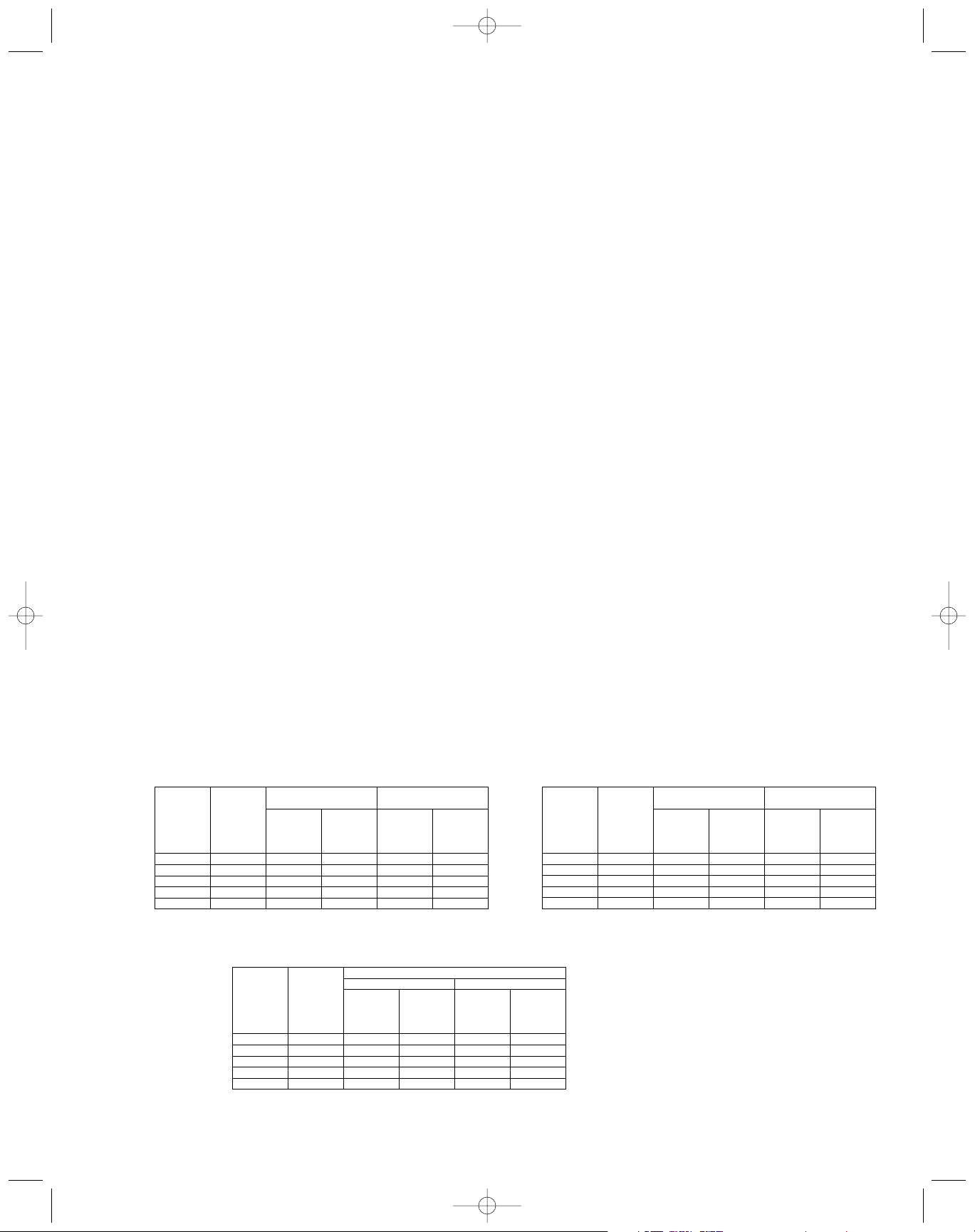
NOTE: Some actuator external surface
temperatures may reach 230˚ during
use at or near maximum duty cycle.
All ratings are nominal and are based
on actuator being broken-in for
approximately 2500 inches of travel.
WITH 115 V. 60 HZ AC MOTOR
WITH 12 V. DC MOTOR
DUTY CYCLE CHART
1-1. General
This page provides instructions for operation and maintenance of Duff-Norton® 3405 and 6405 Series electromechanical actuators. To ensure efficient, long and satisfactory use of this unit, read and understand the information herein, and follow the instructions closely.
1-2. Industrial Use Only
The actuators described and illustrated in this manual are
intended for industrial use only and should not be used
to lift, support or otherwise transport people unless you
have a written statement from Duff-Norton which authorizes the specific actuator unit, as used in your application, as suitable for moving people.
1-3. Factory Preparation
Each actuator is carefully assembled and tested at the
factory to ensure that the electrical and mechanical components will function properly and that the actuator will
lift its rated load. The motor current draw is checked to
make certain that it is within Duff-Norton standards.
Every effort has been made to deliver this unit to
you in its factory approved state. You should, however,
carefully inspect the actuator for damage that may have
occurred during transit.
1-4. Friction Disc Clutch
The friction disc clutch is set so that the actuator will lift
its rated load, or a lighter load if so specified, but will slip
should the actuator be run into a jamming position at the
end of its travel. Thus, under overloads, or jamming conditions, the clutch will slip while the motor continues to
run. If necessary, the clutch can be set to slip at a lighter
load by connecting an ammeter in the line at the motor,
loading the actuator, and, while operating, loosening the
clutch hex nut slightly until ammeter reads the required
current draw. (See table below.) Clutch is not effective
at loads of 50 pounds or less.
1-5. Warranty and Warranty Repair
Subject to the conditions stated herein, Duff-Norton will
repair or replace, without charge, any parts proven to
Duff-Norton’s satisfaction to have been defective in
material and workmanship. Claims must be made within
one year after date of shipment. Duff-Norton will not
repair or replace any parts that become inoperative
because of improper maintenance, eccentric loading,
overloading, chemical or abrasive action, excessive heat,
or other abuse.
Equipment and accessories not of Duff-Norton’s
manufacture are warranted only to the extent that they
are warranted by the manufacturer, and only if the
claimed defect arose during normal use, applications and
service. Equipment which has been altered or modified
by anyone without Duff-Norton’s authorization is not warranted by Duff-Norton. EXCEPT AS STATED HEREIN,
DUFF-NORTON MAKES NO OTHER WARRANTIES,
EXPRESS OR IMPLIED, INCLUDING WARRANTIES OR
MERCHANTABILITY AND FITNESS FOR A PARTICULAR
PURPOSE.
If you have any questions concerning warranty
repair, please contact Duff-Norton.
Authorization for return must be received from
Duff-Norton before returning any equipment for inspection or warranty repair.
2-1. To install the actuator, simply support and secure it
# Total inches travel (up and down) per hour with equally timed intervals
between cycles.
6405-100 10/10/06 11:50 AM Page 3
Speed
3405 Series 6405 Series
Applied Applied Optional Optional
Load Load High Speed High Speed
(lbs.) (lbs.) Motor Motor
100 100 42 80 2.40 4.50
200 200 41 75 2.45 4.60
250 300 39 73 2.50 4.65
N/A 400 37 70 2.55 4.70
N/A 500 35 68 2.60 4.80
3405 Series 6405 Series
Applied Applied Standard High Speed
Load Load 28-33 mfd 64-77 mfd High Speed
(lbs.) (lbs.) Capacitor Capacitor DC Motor
100 100 600 490 2800 1350
200 200 575 485 1750 1000
250 300 550 470 1050 700
N/A 400 525 465 650 –
N/A 500 500 450 350 –
(in/min)
Standard
Motor
Amps
Standard
Motor
# Duty Cycle (inches per hour)
AC Motor
Standard
DC Motor
DC Motor
Speed
3405 Series 6405 Series
Applied Applied Standard Optional Optional
Load Load Motor High Speed High Speed
(lbs.) (lbs.) (MPD-6405) Motor Motor
100 100 68 145 6 21
200 200 60 132 10 28
250 300 52 120 13 36
N/A 400 42 – 17 –
N/A 500 32 – 22 –
(in/min)
(HMPD-6405)
Standard
Motor
Amps
Page 4

with a single pin through one clevis end, secure it to its
load with a second clevis pin, and then use the appropriate wiring diagram (AC or DC, Figure 2-1 or 2-2) to connect the actuator to your power source.
2-2. Avoid using a low voltage supply for the actuator,
All wiring, switches, and other electrical components
must be of sufficient capacity to carry the required current.
2-3. The translating tube is not keyed, and must be
restrained from rotating.
2-4. The axes of the clevis pins should be parallel so
that the actuator can pivot without binding. A few drops
of oil should be applied to the clevis pins on installation
and periodically thereafter.
2-5. External wires for customer hookup are color coded
as to direction of travel (see wiring diagrams, Figure 2-1
or 2-2).
SECTION I
DIMENSIONS AND SPECIFICATIONS
SECTION II
INSTALLATION
FIGURE 1-1
FIGURE 2-1 FIGURE 2-1
Note: Dimensions are subject to change without snotice.
To protect the actuator and prevent damage from
overtravel, it is recoommended that travel limiting
switches be incorporated in the installation.
CAUTION
6405-100 10/10/06 11:50 AM Page 4
Page 5

3-1. A.C. Motor
This motor is an intermittent duty type motor having a
five minute rating. Since the motor draws almost the
same amperage at no load as at full rated load, it only
takes 5 minutes of continuous running, regardless of how
light the load may be, before the thermal overload relay
cuts out. It then takes about 10 minutes before the
motor cools sufficiently for the thermal relay to close.
Make sure that the duty cycle to which the actuator is
subjected is not too severe for the motor. The rear end
bell of the motor has a rubber grommet, which when
removed, exposes a hole threaded for 1/2” NPT (SPB).
3-2. Voltage Supply
Avoid using a low voltage supply for the 115 Volt AC
motor.
Avoid using a voltage supply lower than 11 volts D.C.
3-3. Clevis Pins
The axes of the clevis pins should be parallel so that the
actuator can pivot without binding. A few drops of oil
should be used on the clevis pins.
SECTION III
OPERATIONAL PRECAUTIONS
SECTION IV
MAINTENANCE
4-1. Lubrication
Duff-Norton recommends the use of the following lubricant in conjunction with proper maintenance procedures
of this unit: Exxon Ronnex Exra Duty #1.
4-2. Required Tools
A bearing puller and press, soft jaw table clamp and
common hand tools are required for proper disassembly
and assembly.
4-3. General Procedures
Duff-Norton recommends following these procedures
during disassembly and assembly:
1. Tag critical parts to facilitate reassembly.
2. Mark mating surfaces to ensure proper meshing.
3. Clean and lubricate parts as required.
4. All seals must be replaced at time of rebuild.
5. All screws, washers and other small common parts
must be replaced if mutilated in any way.
4-4. Disassembly
Disassemble the 6405 Series Mini-Pac™ actuator as follows while referring to Figure 5.1. Read instructions thoroughly before disassembling.
1. Clamp housing (13) in vice - use soft jaws.
2. A. D.C. Unit
I. Loosen screws (1) (back end of motor (3)
from motor adaptor (9) (do not remove
screws from motor).
II. Remove motor (3) from motor adaptor (9) (use
screw driver to separate motor end
from adaptor), Taking care that motor end
bells do not separate from motor shell.
B. A.C. Unit
I. Remove socket head cap screws (1) and
lock washers (2) from motor (3) and remove
motor (3) from motor adaptor (9).
3. D.C. Unit - Remove brake springs (7) from motor adaptor (9) and brake cam (6) from pinion (12).
4. Remove screws (8) from housing (13) and remove
motor adaptor (9).
5. Remove pinion (12) and bearing (11) from housing.
6. Remove retaining ring (10) from pinion (12) and remove
(11) from pinion (12).
7. Clamp housing (13) clevis end in vice (use soft jaws),
remove set screw (17) from housing (13).
8. Unscrew outer tube (22) from housing (13) and remove
translating tube (32), screw (25), gear (19) and outer tube
(22) from housing (13).
9. Remove translating tube (32) from outer tube (22) by
slipping outer tube (22) over translating tube (32) towards
clevis end (35).
10. Remove seal (24) from outer tube (22) and press
guide bushings (23) from outer tube (22) and press guide
bushing (23) from outer tube (22) (seal guide bushing
need not be removed unless damaged).
11. Support screw (25) end taking care not to damage
gear (19) teeth. With a 3/16 diameter punch, drive pin
(18) from screw (25), remove gear (19) bearing (20) and
washer (21) from screw (25).
12. Thread screw (25) part way out of nut (27) and check
screw (25) and nut (27) for wear (there should not be
excessive lay between screw and nut thread). If screw or
nut are not excessively worn, the disassembly of screw
(25), nut (27) and translating tube (32) will not be necessary unless clutch must be replaced.
13. Pins (31) should be approximately 3/32 above translating tube (32) OD. Grind pins (31) flush with OD of
6405-100 10/10/06 11:50 AM Page 5
Page 6

translating tube (32).
14. Using 3/16 diameter punch drive pins (313) far
enough into the lifting nut (27) to just clear the translating
tube (32) wall. (Do not drive pins against OD of screw
(25).) Remove nut (27) with screw (25) from translating
tube (32).
15. Remove screw (25) from nut (27).
16. Remove pins (31) from nut (27) by driving pins (31)
remaining distance into ID of nut (27).
17. Remove stop pin (26) from screw (23).
18. Drive pin (34) from clevis end (35).
19. While restraining hex cap screw (28) from rotating,
remove clevis (35) from cap screw (28). (Cap screw can
be restrained from turning by using a 3/4 hex socket with
long extension into translating tube (32) ID.)
20. Remove lock nut (33) from cap screw (28).
21. Remove Belleville spring washers (30) and thrust
washer (29).
22. Remove cap screw (28), Belleville washers (30) and
thrust washer (29) from ID of translating tube (32).
23. Drive pin (4) from motor (3) shaft and remove coupling
(5) and remove damper (36) from I.D. of coupling. Note if
coupling is not damaged, it need not be removed.
24. A.C. unit - ball brake disassembly. Remove set
screws (7c) from ball housing (6) and remove springs (7b)
and balls (7a) and remove drive coupling (5) from ball
housing (6).
25. If bushing (16) in housing (13) is worn remove.
26. If bushing (14) in housing (13) clevis is worn, press
bushing (14) out.
27. If bushing (15) in housing (13) is worn, press bushing
out.
DISASSEMBLY IS COMPLETE.
4-5. Assembly:
1. A. Install damper (36) into coupling (5) I.D. and assemble drive coupling (5) with hole in motor (3) shaft and
install pin (4).
B. A.C. Unit Only
I. Assemble ball housing (6) on drive coupling (5)
(line up ball cavities with groove in
coupling, assemble balls (7a), spring (7b) into
ball cavity and thread set screw (7c) into ball
housing (6), adjust set screws (7c) until torque
required to turn motor (3) shaft and coupling
(5) is 22 oz./in to 28 oz./in., while restraining ball
housing (6) from rotating. (note set screw (7c)
will be approximately flush with OD of ball housing (6).)
2. Assemble bearing (11) on pinion (12) and install retaining ring (10) on pinion (12).
3. Apply Loctite retaining compound (or equal) to OD of
bushing (15) and install in housing (13) (assemble into
housing (13) end opposite side of housing with (4) holes
for mounting motor adaptor (9).
4. Press bushing (14) in housing (13) clevis.
5. Press bushing (16) in housing (13).
6. Install pinion (12) bearing (11), retaining ring (10) into
housing (13).
7. Assemble motor adaptor (9) onto housing (13) holding
in place with screws (8).
8. Press bushing (23) into outer tube (22).
9. Install seal (24) in outer tube (22) (seal scraper should
be facing inward).
10. Apply a generous coat of Shell Darina EP2 grease to
thrust washer (30) and assemble thrust washer (30) and
Belleville washers (29) on hex cap screw (28) (see figure
4-1 for proper installation of washer).
FIGURE 2-1
SLIP CLUTCH ASSEMBLY
6405-100 10/10/06 11:50 AM Page 6
Page 7

11. Install hex cap screw (28), washer (30) and Belleville
washers (29) into ID of translating tube (32) (use 3/4 hex
socket with extra long extension).
12. With hex cap screw (28) threads extending out of
translating tube (32)end, apply a generous coat of Exxon
Ronnex Extra Duty #1 grease to thrust washer (30) and
assemble thrust washer (30), Belleville washers (29) on
hex cap screw (28). (See figure 4-1 for proper installation
of washers.)
13. Assemble lock nut (33) on hex cap screw (28), torque
lock nut (33) down to 30 in./lbs.
14. Assemble clevis (35) on hex cap screw (28). Drill 1/8
hole thru clevis end and hex hex cap screw (28) and lock
in place with pin (3 4) (see figure 4-1). Note: Set slip
torque at final assembly for desired slip load.
15. Assemble nut (27) on screw (25). (Flange of nut (27)
towards turned end of screw (25).)
16. Install stop pin (26) into screw (25) taking care to cen-
ter pin.
17. Fill translating tube (32) approximately half full with
Exxon Ronnex Extra Duty #1 grease.
18. Assemble nut (27) into translating tube (32) (align
holes in translating tube with holes in nut). Install pins (31)
(pins should be 1/32 inch above OD of tube). New pins
should be used.
19. Assemble washer (21) on screw (25).
20. Assemble bearing (20) on gear (19) and assemble on
screw (25) and install pin (18) (pin should be centered
when assembled). Take care not to damage gear teeth.
21. Clamp housing (13) in vice (use soft jaws gear cavity
up.) Fill cavity approximately to centerline of pinion (12)
with Exxon Ronnex Extra Duty #1 grease.
22. Assemble translating tube (32), bearing (20) and gear
(19) assembly into housing (13) taking care not to damage
gear (19) teeth. (Rotate pinion (12) while assembling to be
sure of proper mesh of gear (19) teeth and pinion (12)
thread).
23. Grease OD of translating tube (32) with Exxon Ronnex
Extra Duty #1.
24. With translating tube (32) extended approximately 31/2” to 4” from washer (21), assemble outer tube (22) on
translating tube (32) and thread outer tube (22) into housing (13), against bearing (20) (torque in place at 40 foot
pounds plus or minus 10 foot pounds).
25. Spot drill outer tube (22) thru set screw (17) hole (use
drill slightly smaller than ID of thread). Remove chips and
install set screw (17) and lock in place against outer tube
(22).
26. A. A.C. Unit
I. Align keyway in ball housing (6), and coupling
(5) flats with key in motor adaptor (9) and flats of
pinion (13), assemble motor (3) on motor adaptor
(9) and secure in place with socket head cap
screws (1) and lock washers (2).
B. D.C. Unit
I. Assemble brake cam (6) on pinion (12).
II. Install brake spring (7) into motor adaptor
(9) (see figure 4-2).
III. Taking care that motor (3) end bells do not
separate from motor (3) shell, align drive coupling (5) pins as shown in figure 4-2 and assemble motor (3) to motor adaptor (9) holding in
place with screws (1).
ASSEMBLY IS COMPLETE.
6405-100 10/10/06 11:50 AM Page 7
Page 8

SECTION V
ILLUSTRATED PARTS LIST
Parts List for Duff-Norton 3405 and 6405 Series with Slip Clutch
*Dash No. Equal to Travel of Actuatorr
6405-100 10/10/06 11:50 AM Page 8
Index Part Name
1 Screw 4 S-49-94
2 Lock Washer 4 H-4081-P
3 Motor 1 SK-6405-22 1 SK-6405-14-2
3 Motor (High Speed) 1 SK-2374-43 1 SK-6505-32-1
4 Pin (Coupling) 1 S-50-68 1 H-5249
5 Coupling 1 SK-2374-20 1 SK-6505-150
6 Brake Cam 1 SK-2374-19
6 Ball Housing 1 SK-6405-26
7 Spring 2 SK-2374-18
7a Set Screw 4 S-7-121
7b Compression Screw 4 SK-6505-39
7c Roller Ball 4 SK-6405-20
8 Screw 4 SK-2374-25 4 SK-2374-25
9 Motor Adaptor 1 SK-2374-2 1 SK-6505-149
10 Retaining Ring 1 SK-2374-8 1 SK-2374-8
11 Bearing 1 SK-2374-5 1 SK-2374-5
12 Pinion 1 SK-2374-3 1 SK-2374-3
13 Housing St'd 1 SK-2374-1 1 SK-2374-1
13 Housing 90˚ 1 SK-2374-79 1 SK-2374-79
13 Housing Th'd 1 SK-6505-15 1 SK-6505-15
14 Bushing (Clevis) 1 SK-6405-4 1 SK-6405-4
15 Bushing 1 SK-2374-10 1 SK-2374-10
16 Bushing 1 SK-2374-11 1 SK-2374-11
17 Set Screw 1 S-7-94 1 S-7-94
18 Pin (Gear) 1 H-5167 1 H-5167
19 Gear 1 SK-2374-4 1 SK-2374-4
20 Bearing 1 SK-2374-6 1 SK-2374-6
21 Washer 1 SK-2374-9 1 SK-2374-9
22 Outer Tube 1 SK-6405-12-* 1 SK-6405-12-*
23 Guide Bushing 1 SK-2374-26 1 SK-2374-26
24 Seal 1 SK-2374-16 1 SK-2374-16
25 Screw 1 SK-2374-12-* 1 SK-2374-12-*
26 Pin (Stop) 1 H-5159 1 H-5159
27 Nut 1 SK-2374-13 1 SK-2374-13
28 Hex Head Cap Screw 1 SK-2374-70 1 SK-2374-70
29 Belleville Spring Washer 4 SK-2374-71 4 SK-2374-71
30 Thrust Washer 2 SK-2374-72 2 SK-2374-72
31 Pin (Nut) 2 H-5160 2 H-5160
32 Translating Tube 1 SK-6405-25-* 1 SK-6405-25-*
33 Hex Lock Nut 1 SK-2374-78 1 SK-2374-78
34 Pin (Clevis) 1 H-5169 1 H-5159
35 Clevis End 1 SK-6405-11 1 SK-6405-11
36 Damper 1 SK-6505-152
MPD 6405 (DC)
MPD 3405 (DC) SPB-3405 (AC)
Qty. Qty.
Req'd Req'd
SPB-6405 (AC)
Part No. Part No.
Page 9

6405-100 10/10/06 11:50 AM Page 9
Page 10

SECTION VI
TECHNICAL ILLUSTRATIONS
FIGURE 6-1 LIMIT SWITCH WIRING DIAGRAM
6405-100 10/10/06 11:50 AM Page 10
Page 11

NOTES
6405-100 10/10/06 11:50 AM Page 11
Page 12

P.O. Box 7010 • Charlotte, NC 28241-7010
Phone: (800) 477-5002 • (704) 588-4610
Fax: (704) 588-1994
Email: duffnorton@cmworks.com
www.duffnorton.com
© Yale Industrial Products, Inc., Duff-Norton Division, 2006
All rights reserved by Yale Industrial Products, Inc., Duff-Norton Division.
May not be copied in whole or in part.
Printed in the USA
ECO 99057
1M\SK6405-100\0906
6405-100 10/10/06 11:50 AM Page 12
 Loading...