

Page 1
Publication Part No.
SK-2463-22
Translating Tube Actuators
Model Numbers M-2464 & M-2465
Rotating Screw Actuators
Model Numbers M-2462 & M-2463
CAUTION
This manual contains important information for the correct installation, operation and maintenance of the
equipment described herein. All persons involved in such installation, operation, and maintenance should be
thoroughly familiar with the contents. To safeguard against the possibility of personal injury or property
damage, follow the recommendations and instructions of this manual and keep it for further reference.
WARNING
Improper use can result in personal injury. To avoid injury:
• Do not use actuators to lift, support, or transport people or
loads over people without written approval from Duff-Norton.
• Read all product warnings and operating instructions.
Page 2

Contents
Section I Introduction.................................................................................................................3
1-1. General...............................................................................................................3
1-2. Intended Use .......................................................................................................3
1-3. Safety Considerations.........................................................................................3
1-4. Unwarranted Applications....................................................................................3
1-5. Warranty and Warranty Repair ............................................................................3
Section II Installation ..................................................................................................................3
2-1. Motor Installation .................................................................................................3
2-2. Installation of the Actuator ...................................................................................3
2-3. Limit Switches......................................................................................................3
Section III Dimensions and Specifications...................................................................................4
3-1. Dimensions - Rotating Screw Actuators .............................................................4
3-2. Dimensions - Translating Tube Actuators............................................................4
3-3. Specifications .....................................................................................................5
Section IV Operation, Maintenance, and Inspection....................................................................5
4-1. Improper Loading ...............................................................................................5
4-2. Clevis Pins..........................................................................................................5
4-3. Lubrication ..........................................................................................................5
4-4. Inspection ...........................................................................................................5
Section V Disassembly and Assembly........................................................................................6
5-1. Lubricant.............................................................................................................6
5-2. Required Tools....................................................................................................6
5-3. General Procedures ...........................................................................................6
5-4. Disassembly - Rotating Screw Actuators (Models M-2462 and M-2463) ...........6
5-5. Assembly - Rotating Screw Actuators (Models M-2462 and M-2463)................6
5-6. Disassembly - Translating Tube Actuators (Models M-2464 and M-2465)..........8
5-7. Assembly - Translating Tube Actuators (Models M-2464 and M-2465)...............8
Section VI Illustrated Parts List ............................................................................................... ...10
6-1. General.............................................................................................................10
6-2. Parts List for Rotating Screw Actuators............................................................11
6-3. Parts List for Translating Tube Actuators (Models M-2464 and M-2465) ..........12
2
Page 3

Section I
Introduction
1-1. General
This manual provides instructions for the installation, operation, and maintenance of the Duff-Norton® Modular
Actuator. It includes proper procedures for the disassembly , cleaning, inspection, rebuilding, lubrication, and
assembly of the actuator. To ensure efficient and long,
satisfactory use of this unit, read and understand the
information herein, and follow the instructions closely.
1-2. Intended Use
The Duff-Norton® Modular Actuators described and illustrated in this manual are intended for industrial use
only and should not be used to lift, transport, or otherwise support people.
1-3. Safety Considerations
1. Avoid touching exterior surfaces of the actuator.
Surface temperatures may reach 230 ° F during
prolonged use.
2. Make certain that the electric motor used conforms
to the requirements of the actuator.
1-4. Unwarranted Applications
CAUTION
These actuators are not recommended
or warranted for use in applications involving the following activities or
conditions:
1. Lifting, supporting, or positioning of people where
a malfunction might result in bodily injury.
2. Side loading or binding of the actuator. (See Par agraph 4-1, "Improper Loading".)
NOTE
If in doubt about the suitability of the actuator for you application, consult the Duff-Norton
Engineering Department.
1-5. Warranty and Warranty Repair
Subject to the conditions stated herein, Duff-Norton will
repair or replace, without charge, any parts proven to DuffNorton’s satisfaction to hav e been defectiv e in material or
workmanship. Claims must be made within one year after date of shipment. Duff-Norton will not repair or replace
any parts that become inoperative because of improper
maintenance, eccentric loading, overloading, chemical or
abrasive action excessive heat, or other abuse
Equipment and accessories not of Duff-Norton’s manufacture are warranted only to the extent that they are
warranted by the manufacturer, and only if the claimed
defect arose during normal use, applications and service.
Equipment which has been altered or modified by anyone
without Duff-Norton’s authorization is not warranted by
Duff-Norton. EXCEPT AS STATED HEREIN, DUFFNORT ON MAKES NO OTHER WARRANTIES, EXPRESS
OR IMPLIED, INCLUDING WARRANTIES OF MERCHANTABILITY AND FITNESS FOR A PARTICULAR
PURPOSE.
If you have any questions concerning warranty repair,
please consult a Duff-Norton Warehouse and Customer
Service Center for the name and address of your nearest
Duff-Norton actuator warranty repair facility.
Authorization for return must be granted b y the Duff-Norton
Company before any equipment may be returned for inspection or warranty repair.
Section II
Installation
Duff-Norton's Modular Actuator is designed to be a versatile piece of equipment which can be used in many
different applications; consequently, installation procedures will vary widely with customer requirements
2-1. Motor Installation
The Modular Actuator is designed to accept a standard
NEMA 56 frame electric motor with C-face mounting, to
be supplied by the customer. For instructions on installing the motor on the actuator, see Paragraph 5-5, steps
19-21 (these steps apply to both Rotating Screw and T ranslating Tube actuators).
2-2. Installation of the Actuator
The actuator has two bolt patterns for convenient attach-
ment of the actuator to the application: both the tw o-hole
pattern (17/32-inch unthreaded holes 4 inches apart) and
the four-hole pattern (1/2-20 threaded holes on a 2.55
inch square) can be used to bolt the actuator to a wide
variety of mounting points; the four-hole pattern will also
accept standard hydraulic type end fittings.
The lifting nut (on Rotating Screw actuators) and the clevis
end (on Traslating Tube actuators) must be restrained
against rotation in order for the actuator to lift its load.
2-3. Limit Switches
Duff-Norton recommends that limit switches be incorporated in the installation to prevent o vertravel of the actuator
in either direction and to protect the actuator against internal jamming. Duff-Norton limit switches to fit this
actuator are available at an additional cost.
3
Page 4
Section III
Dimensions and Specifications
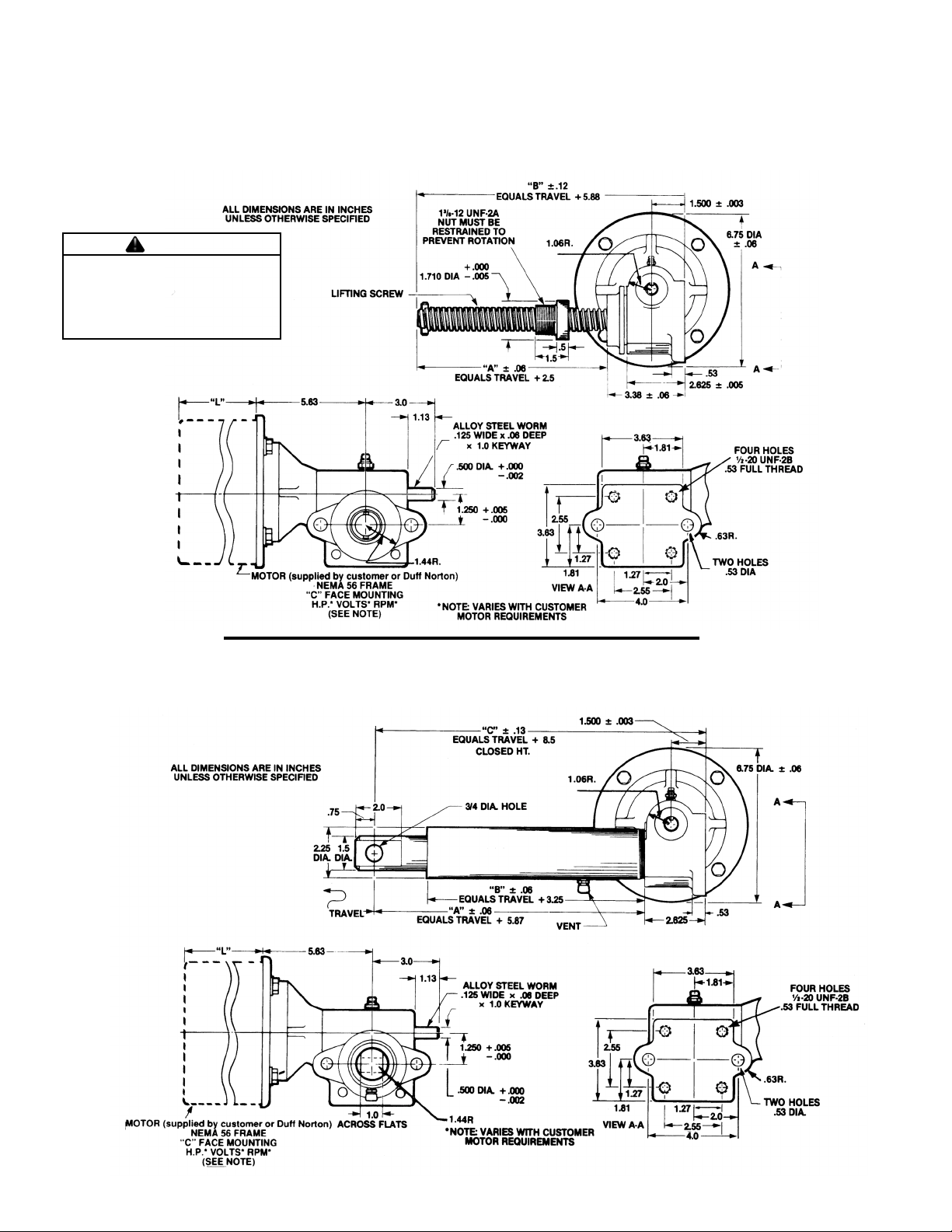
3-1. Dimensions - Rotating Screw Actuators (Models M-2462 and M-2463)
Warning
Use only replacement parts supplied
by or approved by Duff-Norton. Nonauthorized parts may be inadequate,
resulting in serious injury or death
in event of failure.
3-2. Dimensions - Translating Tube Actuators (Models M-2464 and M-2465)
4
Page 5
q
g
p
p
p
p
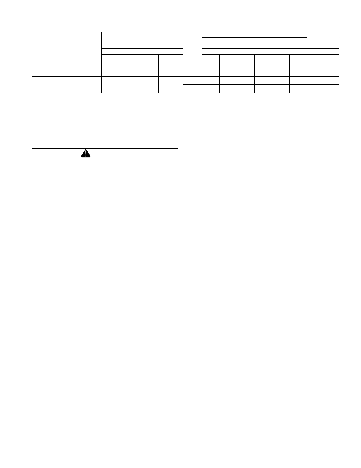
3-3. Specifications
Tor
Model No. Screw Dia.
M-2462
M-2464
M-2463
M-2465
NOTE: 1. Models M-2462 and M-2464 are self-lowering and a motor brake should be used.
.875 Dia. Acme
.25 Pitch
R.H. Double
1.0 Dia. Acme
.25 Pitch
R.H. Single
2. Models M-2463 and M-2465 may drift 0.75 in (20:1 ratio) to 2.0 in (5:1 ratio) when the motor is shut off. If this is undesirable, a motor brake should be used.
Worm/ 1"
Travel
Ratio Ratio Ratio
5:1 20:1 5:1 20:1 5:1 20:1 5:1 20:1 5:1 20:1 5:1 20:1
10 40 39 18
20 80 29
ueTurns of Liftin
lb/in @
1000 lb Load
14
Motor
RPM
1725 300 700 500 1000 700 1500 170 43
1140 450 1000 700 1500 1100 2000 114 28
1725 400 900 600 1400 900 2000 8 6 2 1
1140 600 1400 900 2000 1400 2000 57 1 4
1/3 h
Motor Motor
Rated Load
1/2 h
Ratio
3/4 h
Motor
Ratio
Section IV
Operation, Maintenance, and Inspection
4-1. Improper Loading
Warning
The actuator must NOT be subjected to side
loading or binding (i.e., a bending moment
across the actuator) at any point in its travel. It
is the responsibility of the installer to ensure
that the mounting points cannot transmit such
loading to the actuator anywhere between full
retraction and full extension. F ailure to observe
this warning will void the warranty on the actuator.
4-2. Clevis Pins
The axes of the clevis pins should be parallel so that the
actuator can pivot without binding. A few drops of oil should
be applied to the clevis pins on installation and periodically thereafter.
4-3. Lubrication
The actuator is lubricated at the factory with Shell Albida
LC EP#2 (Shell Oil Co. product code 70311). This grease
has been thoroughly evaluated b y Duff-Norton and demonstrated to provide superior actuator life. Other greases
may provide satisfactory service, with some acceleration
of wear. Only high quality, NLGI #2EP, lithium based
greases should be used.
The actuator should be lubricated periodically (see NOTE
under Paragraph 4-4, "Inspection"), using the grease fitting. On Rotating Screw actuators, the lifting screw and
nut can be lubricated by painting a light coat of grease on
the screw at a point that passes through the nut. To lubricate the lifting screw and nut on a Translating Tube
actuator, first loosen the set scre ws and unscrew the outer
tube from the housing to expose the lifting screw threads .
The actuator should be disassembled, cleaned, inspected,
and relubricated after 500,000 inches of travel under normal conditions, or earlier if the need is indicated by
inspection or by a squealing from the lifting screw and nut
area. Follow the instructions in Section V to o verhaul the
actuator.
4-4. Inspection
The actuator should be inspected periodically (see NOTE
below), with attention given to the following items:
1. Clevis ends for wear , cracks, distortion, or other degradation or damage.
2. Loose belts, screws, or other hardware on the actuator or its mounting points.
3. Limit switches (if so equipped) for proper setting and
operation.
4. Lifting screw, lifting nut, and gear set for excessive
wear or lack of lubrication (see instructions under
Paragraph 4-3, "Lubrication").
Any of the above deficiencies should be corrected bef ore
the actuator is returned to service.
NOTE
Periodic Inspection and Lubrication: The exact periods for inspection and lubrication of
the actuator cannot be predetermined because of the many variables involved, such
as frequency of operation, type and magnitude of loading, and operational environment.
Determination should be based on the user's
experience. It is recommended that the user
begin with a weekly inspection, extending the
inspection period to monthly, quarterly, or
annually, based on his weekly experience.
S
eed
in/min
Ratio
5
Page 6

Section V
Disassembly and Assembly
5-1. Lubricant
When rebuilding this actuator, use only Albida LC EP#2
grease from Shell Oil Company.
5-2. Required Tools
A bearing puller and press, a soft jaw table clamp, and
common hand tools are required for proper disassembly
and assembly of the actuator.
5-3. General Procedures
Duff-Norton recommends following these procedures during disassembly and assembly of the actuator:
1. Tag critical parts to facilitate reassembly.
2. Mark mating surfaces to ensure proper meshing.
3. Clean and lubricate parts as required.
4. Replace all seals at time of rebuild.
5. Replace any screws, washers, and other small common parts that are damaged in any way.
5-4. Disassembly - Rotating Screw Actuators (Models M-2462 and M-2463)
Disassemble the Duff-Norton® Rotating Screw Modular
Actuator as follows, referring to Figure 6-1 on page 11.
Read the instructions thoroughly before disassembling the
actuator.
NOTE
For disassembly procedures for Translating
Tube actuators, see Paragraph 5-6.
NOTE
Disassembly should be undertaken on a
clean cloth.
1. Remove the f our cap scre ws (B) with loc k w ashers
(F) that attach the motor (A) to the shell (9) flange,
and remove the motor from the shell. Half the fle xible coupling (5a) will come with the motor shaft,
and the other half (5a) will remain on the worm shaft
(4). The flexible spider (5b) may stay with either
half of the coupling.
2. Remove the set screw (5c) from the motor half of
the coupling (5a), and remove the coupling half and
the key (E) from the motor shaft.
3. Remove the pipe plug (7) and the grease fitting (8)
from the shell (9).
4. Remove the set screw (5c) from the worm half of
the coupling (5a) by inserting the set screw wrench
through the pipe plug hole.
5. Remove the coupling half (5a) and the ke y (18) from
the worm shaft (4).
When disassembling an actuator equipped with limit
switches, f ollow steps 6 and 7 below . If the actuator is not
equipped with limit switches, proceed directly to step 8.
6. Remove the two socket head cap screws (28) and
the one long hex head cap screw (26) from the limit
switch adaptor (29), and remov e the limit switch box
(D) from the limit switch adapter.
7. Remove the two half dog point sets screws (30) from
the shell (9) and remove the limit switch adapter
(29) from the shell (see NOTE below).
NOTE
It may be necessary to use heat to overcome
the adhesive in order to remove the limit
switch adapter from the shell.
8. Remove the two set scre ws (10) from the shell (9),
and unscrew the shell cap (19) from the shell.
9. Remove the shell cap, lifting screw, bearing, and
gear assembly from the shell (9).
10. Remove the retaining ring (1) from the shell (9).
11. Remov e the worm (4) by pressing on the motor end
of the worm shaft. The worm bearing (2) next to
the retaining ring (1) groove will be driven out by
the worm. The other worm bearing (2) should remain in the shell until the load bearing cup (13) has
been removed.
12. Press the worm bearing (2) off the worm (4).
13. Remove the load bearing cup (13) out of the shell
(9).
14. Remove the remaining worm bearing (2) from the
shell (9).
15. Clamp the lifting screw (17) in a vise, using soft ja ws
to prevent damage to the screw.
16. Remove the lock n ut (12), and remove the gear (14),
key (18), and spacer (15) from the lifting screw (17).
17. Remove the shell cap (19) and lifting nut (20) from
the lifting screw (17).
18. Remov e the stop pin (16) from the lifting screw (17)
if necessary.
19. Remove the two load bearing cones (13) from the
gear (14).
Disassembly of the actuator is now complete.
5-5. Assembly - Rotating Screw Actuators (Models M-2462 and M-2463)
Assemble the Duff-Norton® Rotating Screw Modular Actuator as follows, ref erring to Figure 6-1 on page 11. Read
the instructions thoroughly before assembling the actuator.
6
Page 7

NOTE
For assembly procedures f or Translating Tube
actuators, see Paragraph 5-7.
NOTE
Be sure all parts are clean and dr y before
assembling the actuator.
1. Assemble one load bearing cup (13) into the shell
(9), and the other load bearing cup into the shell
cap (19).
2. Assemble one worm bearing (2) into the motor
mounting flange end of the shell (9) (see NOTE below).
NOTE
The bearing must be installed from the opposite end of the shell.
3. Notice that one end of the worm (4) has a hole in
the center of the shaft, and one end does not. Press
the remaining worm bearing (2) on to the end of the
shaft WITH the hole.
4. Assemble the worm (4) into the shell (9) and worm
bearing (2), and then install the retaining ring (1) in
the shell.
5. Grease the two load bearing cones (13) and install
them on the worm gear (14) bearing journals.
6. Install the stop pin (16) in the end of the lifting screw
(17), taking care to center the pin in the screw.
7. Screw the lifting nut (20) on to the lifting screw (5)
with the flange end away from the stop pin (16).
8. Slide the shell cap and bearing cup assembly over
the lifting screw threads, with the bearing cup (13)
facing the turned end of the lifting screw.
9. Slip the spacer (15) over the end of the lifting screw
(17), with the flange toward the screw thread.
10. Install the ke y (18) in the ke yway in the lifting scre w
(17).
11. Slide the gear and load bearing cone assembly over
the end of the lifting screw (17).
12. Thread the lock nut (12) on to the end of the lifting
screw (17). Clamp the lifting screw between soft
jaws in a vise, and tighten the lock nut to 30 ft-lb.
13. Install the lifting screw, shell cap , and gear assembly in the shell (9), taking care to mesh the gear
teeth and the worm properly.
14. Pack the gear housing with Shell Albida LC EP#2
grease.
15. Coat the shell cap (19) threads with aluminum
antiseize compound. Thread the shell cap into the
shell (9), and torque it to 40 ft-lb. Spot drill the shell
cap thread O.D. in two places, and install the two
set screws (10). Tighten the set screws to hold the
shell cap in place.
16. Install the key (6) in the end of the worm (4) shaft
on the flange side of the shell (9), and slide a coupling half (5a) onto the worm shaft. The inside f ace
of the coupling should be flush with the worm shaft
end. Tighten the coupling set screw (5c) against
the key by inserting the set screw wrench through
the 1/8-inch pipe tap hole in the shell.
17. Install the pipe plug (7).
18. Install the grease fitting (8).
19. Install the key (E) in the motor shaft and slide the
second coupling half (5a) on to the motor shaft, with
the inside face of the coupling flush with the end of
the motor shaft. Tighten the coupling set screw
against the key to lock it in place.
20. Assemble the flexible spider (5b) on to the motor
coupling half (5c).
21. Align the motor coupling half (5a) with the worm
coupling half (5a) and assemble the motor (A) to
the shell (9), aligning the holes in the flange with
the tapped holes in the face of the motor. Make
sure that the motor is centered in the counterbore,
and then install and tighten the four 3/8-16 x 7/8
inch hex head cap screws (B) with lock washers
(F) that attach the motor to the flange. Turn the
worm shaft extension by hand to be certain that
there is no binding of the motor and the actuator.
This completes the assembly procedures for actuators not
equipped with limit switches. When assembling an actuator equipped with limit switches, continue with the
instructions below.
22. Apply two or three drops of Loc-Tite No. 35 Extra
Strength Retaining Ring Compound to the shell
bore.
If a new (replacement) limit switch adapter is being installed, follow steps 23 and 24 belo w. If a used (pre viously
spot drilled) adapter is being installed, proceed directly to
step 25.
23. Install the limit switch adapter (29) in the shell (9),
making sure that the adapter bottoms out against
the retaining ring (1). Orient the four tapped holes
in the limit switch adapter to line up with the four
motor mounting holes in the housing flange.
24. Spot drill the limit switch adapter (29) in two places
and install the two half dog point set screws (30).
Proceed directly to step 27.
25. Install the limit switch adapter (29) in the shell (9),
aligning the spot drilled holes in the adapter with
the tapped holes in the shell.
26. Install the two half dog point set screws (30).
27. Aligning the slot in the limit switch worm shaft with
the pin in the actuator worm, install the limit switch
box on the adapter (29) in the desired position.
Assembly of the actuator is now complete.
7
Page 8

5-6. Disassembly - Translating Tube Actuators (Models M-2464 and M-2465)
Disassemble the Duff-Norton® T ranslating Tube Modular
Actuator as follows, referring to Figure 6-2 on page 12.
Read the instructions thoroughly before disassembling the
actuator.
NOTE
For disassembly procedures f or the Rotating
Screw actuators, see Paragraph 5-4.
NOTE
Disassembly should be undertaken on a
clean cloth.
1. Remove the f our cap scre ws (B) with loc k w ashers
(F) that attach the motor (A) to the shell (9) flange,
and remove the motor from the shell. Half the fle xible coupling (5a) will come with the motor shaft,
and the other half (5a) will remain on the worm shaft
(4). The flexible spider (5b) may stay with either
half of the coupling.
2. Remove the set screw (5c) from the motor half of
the coupling (5a), and remove the coupling half and
the key (E) from the motor shaft.
3. Remove the pipe plug (7) and the grease fitting (8)
from the shell (9).
4. Remove the set screw (5c) from the worm half of
the coupling (5a) by inserting the set screw wrench
through the pipe plug hole.
5. Remove the coupling half (5a) and the ke y (6) from
the worm shaft (4).
When disassembling an actuator equipped with limit
switches, f ollow steps 6 and 7 below . If the actuator is not
equipped with limit switches, proceed directly to step 8.
6. Remove the two socket head cap screws (28) and
the one long hex head cap screw (26) from the limit
switch adapter (29), and remov e the limit switch box
(D) from the limit switch adapter.
7. Remove the two half dog point set scre ws (30) from
the shell (9) and remove the limit switch adapter
(29) from the shell (see NOTE below).
NOTE
It may be necessary to use heat to overcome
the adhesive in order to remov e the adapter
from the shell.
8. Remove the two set scre ws (10) from the shell (9),
and remove the outer tube (24) b y first unscrewing
it from the shell and then sliding it off over the translating tube.
9. Remove the translating tube , lifting screw, bearing,
and gear assembly from the shell (9).
10. Remove the retaining ring (1) from the shell (9).
11. Remove the w orm (4) by pressing on the motor end
8
of the worm shaft. The worm bearing (2) next to
the retaining ring (1) groove in the shell (9) will be
driven out by the worm. The other worm bearing
(2) should remain in the shell until the load bearing
cup (13) has been removed.
12. Press the worm bearing (2) off the worm (4).
13. Remove the load bearing cup (13) out of the shell
(9).
14. Remove the remaining worm bearing (2) from the
shell (9).
15. Remove the remaining load bearing cup (13) from
the outer tube (24).
16. Remov e the wiper scraper seal (22) from the outer
tube (24), and if necessary press the guide bushing (23) out of the outer tube.
17. Clamp the lifting screw (17) in a vise, using soft ja ws
to prevent damage to the screw.
18. Remove the lock n ut (12), and remove the gear (14),
key (18), and spacer (15) from the lifting screw (17).
19. Remove the two load bearing cones (13) from the
gear (14).
20. Screw the lifting scre w (17) into the translating tube
until the screw bottoms out and cannot rotate farther, or until the scre w thread becomes disengaged
from the lifting nut (19) thread.
21. (M2464) Drive the f our pins (20) just far enough into
the lifting nut (19) to clear the translating tube wall;
then remove the translating tube from the nut.
(M2465) Remove the set screw (S7-94) from the
translating tube; then remo ve the lifting nut from the
translating tube.
22. Remove the lifting screw (17) from the lifting nut
(19).
23. Remove the four pins (20) by pressing each one
the rest of the way through the lifting nut wall.
24. Remov e the stop pin (16) from the lifting screw (17)
if necessary.
Disassembly of the actuator is now complete.
5-7. Assembly - Translating Tube Actuators (Models M-2464 and M-2465)
Assemble the Duff-Norton® Translating T ube Modular Actuator as follows, ref erring to Figure 6-2 on page 12. Read
the instructions thoroughly before assembling the actuator.
NOTE
For assembly procedures f or Rotating Screw
actuators, see Paragraph 5-5.
NOTE
Be sure all parts are clean and dr y before
assembling the actuator.
1. Assemble a load bearing cup (13) into the shell (9).
Page 9

2. Assemble one worm bearing (2) into the motor
mounting flange end of the shell (9) (see NOTE below).
NOTE
The bearing must be installed from the opposite end of the shell.
3. Notice that one end of the worm (4) has a hole in
the center of the shaft, and one end does not. Press
the remaining worm bearing (2) on to the end of the
shaft WITH the hole.
4. Assemble the worm (4) into the shell (9) and worm
bearing (2), and then install the retaining ring (1) in
the shell.
5. Install the guide bushing (23) and the wiper scraper
seal (22) in the end of the outer tube (24) opposite
the threaded end.
6. Install a load bearing cup (13) in the threaded end
of the outer tube (24).
7. Grease the two load bearing cones (13) and install
them on the worm gear (14) bearing journals.
8. Install the stop pin (16) in the end of the lifting screw
(17), taking care to center the pin in the screw.
9. Screw the lifting nut (19) on to the lifting screw (17)
with the flange end away from the stop pin (16).
10. Fill the translating tube (16) approximately half full
of Shell Albida LC EP#2 grease.
11. (M2464 only) Slide the translating tube and clevis
end assembly over the lifting screw (17) and on to
the lifting nut (19), lining the four holes in the translating tube up with the four holes in the lifting nut
(19).
Press the four pins (20) into place (see CAUTION
below).
CAUTION
The pins should end up extending 1/32
inch beyond the O.D. of the translating
tube, and must NOT jam against the O.D.
of the lifting screw thread. If the pins are
pressed too far into the lifting nut, they
will bind against the lifting screw thread,
perhaps damaging the screw surface.
NOTE
The lifting nut should now rotate freely on the
lifting screw . If the nut does not rotate freely
on the screw , follo w steps 21-24 under P aragraph 5-6, "Disassembly", and then resume
"Assembly" at step 9.
12. (M2465 only) Clean any grease from the external
threads on lifting nut (SK2465-29) and from the internal threads on the translating tube and clevis end
assembly. Apply thread locker (Loctite 242) to the
external threads on the lifting nut. Screw the translating tube and clevis assembly onto the lifting n ut.
Use a drill bit to "spot" the lifting nut and install the
set screw (S7-94).
13. Slip the spacer (15) ov er the end of the lifting screw
(17), with the flange toward the lifting screw shoulder.
14. Install the ke y (18) in the ke ywa y in the lifting screw
(17).
15. Slide the gear and load bearing cone assembly over
the end of the lifting screw (17).
16. Thread the lock nut (12) on to the end of the lifting
screw (17). Clamp the lifting screw between soft
jaws in a vise, and tighten the lock nut to 30 ft-lb.
17. Install the lifting screw, translating tube, and gear
assembly in the shell (9), taking care to mesh the
gear teeth and the worm properly.
18. Pack the gear housing with Shell Albida LC EP#2
grease.
19. Make sure that a load bearing cup (13) has been
installed in the end of the outer tube (24) (see step
6). Lightly grease the O.D. of the translating tube
assembly, and slide the outer tube over the translating tube, threaded end first.
20. Thread the outer tube (24) into the shell (9), and
tighten it to 40 ft-lb. Spot drill the outer tube thread
in two places, and install and tighten the two set
screws (10) to hold the outer tube in place.
21. Install the key (6) in the end of the worm (4) shaft
on the flange side of the shell, and slide a coupling
half (5a) on to the worm shaft. The inside face of
the coupling should be flush with the worm shaft
end. Tighten the coupling set screw (5c) against
the key by inserting the set screw wrench through
the 1/8-inch pipe tap hole in the shell.
22. Install the pipe plug (7).
23. Install the grease fitting (8).
24. Install the key (E) in the motor shaft and slide the
second coupling half (5a) on to the motor shaft, with
the inside face of the coupling flush with the end of
the motor shaft. Tighten the coupling set screw
against the key to lock it in place.
25. Assemble the flexible spider (5b) on to the motor
coupling half (5c).
26. Align the motor coupling half (5a) with the worm
coupling half (5a) and assemble the motor to the
shell (9), aligning the holes of the flange with the
tapped holes in the face of the motor. Make sure
that the motor is centered in the counterbore, and
then install and tighten the four 3/8-16 x 7/8 inch
hex head cap screws (B) with loc k washers (F) that
attach the motor to the flange. Turn the worm shaft
extension by hand to be certain that there is no binding of the motor and the actuator.
9
Page 10

This completes the assembly procedures for actuators not
equipped with limit switches. When assembling an actuator equipped with limit switches, continue with the
instructions below.
27. Apply two or three drops of Loc-Tite No. 35 Extra
Strength Retaining Ring Compound to the shell
bore.
If a new (replacement) limit switch adapter is being installed, follow steps 28 and 29 below . If a used (previously
spot drilled) adapter is being installed, proceed directly to
step 30.
28. Install the limit switch adapter (29) in the shell (9),
making sure that the adapter bottoms out against
the retaining ring (1). Orient the four tapped holes
Section VI
Illustrated Parts List
6-1. General
in the limit switch adapter to line up with the four
motor mounting holes in the housing flange.
29. Spot drill the adapter (29) in two places and install
the two half dog point set screws (30). Proceed
directly to step 32.
30. Install the limit switch adapter (29) in the shell, aligning the spot drilled holes in the adapter with the
tapped holes in the shell.
31. Install the two half dog point set screws (30).
32. Aligning the slot in the limit switch worm shaft with
the pin in the actuator worm, install the limit switch
box on the adapter (29) in the desired position.
Assembly of the actuator is now complete.
This section contains exploded illustrations of DuffNorton® Rotating Screw and Translating Tube Modular
Actuators. The numbers adjacent to each of the parts on
the illustrations is the index number. On the parts listed
below, these numbers are keyed to the individual part
names.
10
Page 11

6-2. Parts List for Rotating Screw Actuators
g
g
)
g
y
g
g
g
(
)
)
)
)
)
)
)
)
Index No.
Figure 6-1
1 1 SK-2501-11
2 2 SK-2501-10
3 1 S-50-26
4 Worm 5:1 Ratio 1
5** 1 SK-2465-21
6 1 S-10-2
7 1 S-25-13
8 1 SK-974-32
9 1 SK-2465-1
10 2 S-7-10
11 1 SK-2433-19
12 1 H-3966-P
13 2 SK-2501-9
* This No. is equal to travel plus 1.
** 5a - coupling body
5b - spider
5c - set screw
Part Name
Retaining Rin
Worm Bearin
Spring Pin (Worm
20:1 Ratio 1
Flexible Couplin
Ke
Pipe Plu
Grease Fittin
Shell
Set Screw
Decal
Lock Nut
Load Bearin
Qty Req.
SK-2465-43
SK-2465-53
Part
Number
Index No.
Figure 6-1
14 Worm Gear 5:1 Ratio 1 SK-3502-4
15 1 SK-2465-17
16 1
17 1
18 1 S-10-72
19 1 SK-2463-2
20 1 SK-2463-6
26 1 S-44-157
27 3 H-4084-P
28 2 H-2201
29 1 SK-2465-11
30 2 S-52-1
Part Name
20:1 Ratio 1 SK-2502-14
Spacer
Stop
Pin
Screw (M-2463
Screw (M-2462
Key (Screw
Shell Cap (M2463
Shell Cap (M2462
Lifting Nut (M-2463
Lifting Nut (M-2462
Hex Hd. Cap Screw
Lock Washer
Soc Hd. Cap Screw
Limit Switch Adapter
Set Screws
Qty Req.
H-5122-P
SK-2465-5-*
1 SK-2464-5-*
1 SK-2462-2
1 SK-2462-6
Warning
Use only replacement
parts supplied by or approved by Duff-Norton.
Non-authorized parts may
be inadequate, resulting in
serious injury or death in
event of failure.
Part
Number
11
Page 12

6-3. Parts List for Translating Tube Actuators (Models M-2464 and M-2465)
g
g
g
g
)
g
y
g
g
Index No.
Figure 6-2
1 1 SK-2501-11
2 2 SK-2501-10
3 1 S-50-26
4 Worm 5:1 Ratio 1
5** 1 SK-2465-21
6 1 S-10-2
7 1 S-25-13
8 1 SK-974-32
9 1 SK-2465-1
10 2 S-7-10
11 1 SK-2433-19
12 1 H-3966-P
13 2 SK-2501-9
14 Worm Gear 5:1 Ratio 1 SK-3502-4
15 1 SK-2465-17
* This No. is equal to travel.
** 5a - coupling body
5b - spider
5c - set screw
Part Name
Retainin
Worm Bearin
Spring Pin (Worm
Flexible Couplin
Ke
Pipe Plu
Grease Fittin
Shell
Set Screw
Decal
Lock Nut
Load Bearin
Spacer
Rin
20:1 Ratio 1
20:1 Ratio 1 SK-2502-14
Qty Req.
SK-2465-43
SK-2465-53
Part
Number
Index No.
Figure 6-2
Pin (Stop)
16
Screw (M-2465)
17
Screw (M-2464) 1 SK-2464-5-*
18 Key (Screw) 1 S-10-72
19 Lifting Nut (M-2465) 1 SK-2465-29
Lifting Nut (M-2464) 1 SK-2415-15
20 Pin (Nut) 4 H-5164
Screw (M-2465) 1 S7-94
21 Tube & Clevis Sub-Assembly (M-2464) 1 SK-6415-109-* A
Tube & Clevis Sub-Assembly (M-2465) 1 SK-2465-31-* A
22 Wiper-Scraper Seal 1 SK-6415-16
23 Guide Bushing 1 SK-6415-23
24 Outer Tube 1 SK-6415-111-*
25 Air Vent 1 SK-2405-218
26 Hex Hd. Cap Screw 1 S-44-157
27 Lock Washer 3 H-4084-P
28 Soc. Hd. Cap Screw 2 H-2201
29 Limit Switch Adapter 1 SK-2465-11
30 Set Screws 2 S-52-1
Part Name Qty Req.
1
1
Part
Number
H-5122-P
SK-2465-5-*
Warning
Use only replacement
parts supplied by or approved by Duff-Norton.
Non-authorized parts may
be inadequate, resulting in
serious injury or death in
event of failure.
12
Page 13

Notes
13
Page 14

© 2000 Yale Industrial Products, Inc.
P.O. Box 7010
Charlotte, NC 28241-7010
Customer Service (800) 477-5002
FAX (704) 588-1994
Email: duffnorton@cmworks.com
www.duffnorton.com
SK2463-22
500/0404
ECO 97804
 Loading...