

Page 1

Duff-N
orton
R
D
R
d
Full-Load
Shippi
Model No. Voltage
LS25-1B5TN-04 AC 450 115VAC 4 16 17 11.4 1.4 9.1
LS25-1B5TN-08 AC 450 115VAC 8 16 17 15.4 1.4 9.8
LS25-1B5TN-12 AC 450 115VAC 12 16 17 19.4 1.4 10.6
LS26-1B5TN-04 AC 560 115VAC 4 13 17 11.4 1.4 9.1
LS26-1B5TN-08 AC 560 115VAC 8 13 17 15.4 1.4 9.8
LS26-1B5TN-12 AC 560 115VAC 12 13 17 19.4 1.4 10.6
LS28-1B5TN-04 AC 675 115VAC 4 9 17 11.4 1.4 9.1
LS28-1B5TN-08 AC 675 115VAC 8 9 17 15.4 1.4 9.8
LS28-1B5TN-12 AC 675 115VAC 12 9 17 19.4 1.4 10.6
ated Load
(Lbs.) Volts Travel (In.)
Speed (In.
/ Min.)
uty
Cycle %
etracte
Length (In.)
Amps
W eight
ng
LS35-3B4TN-12 DC 675 12VDC 12 13 17 19.4
LS35-3B4TN-24 DC 675 12VDC 24 13 17 31.4 10 10.8
LS35-1B4TN-12 AC 675 115VAC 12 16 17 19.4 1.6 10.6
LS35-1B4TN-24 AC 675 115VAC 24 16 17 31.4 1.6 12.8
LS48-S001 AC 660 115VAC 24 9 17 38.75 1.4 21.6
10 8.6
Page 2
Installation & Operating Instructions
1. Application
The LS series actuators are intended for industrial use only and should not be used to lift, support, or otherwise transport people or
loads over people. The actuator is designed for lifting or pushing loads no more than its load rating, on an intermittent basis, not for
applications requiring continuous operation. The actuator is designed for clevis mounting and cannot support side loading of the tubes.
The actuator is not suitable for use in uncovered outdoor locations or areas containing explosive dust, vapors, or gases.
2. Installation
The actuator should be connected with a 10mm (.394”) steel clevis pin at each end. An M10, grade 8.8, DIN 931 cap screw can be
used. Use a screw at least 75mm long to obtain at least 50mm of unthreaded shank.
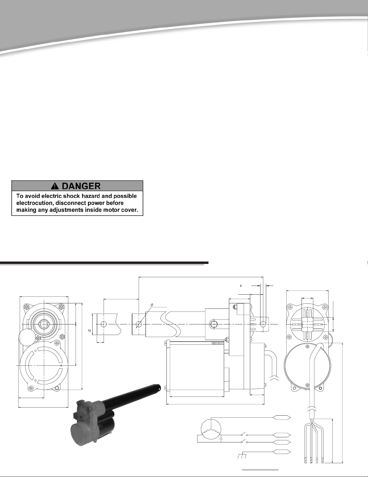
3. Wiring
All electrical connections are made to the pigtail cable. Refer to the diagrams below for 115 Vac and 12 Vdc models. End of travel limit
switches are internally connected. AC units can be operated with a SPDT-center-off switch. DC units require a DPDT-center-off switch.
AC units must be connected according to local electrical codes, with the green wire grounded.
4. Limit Switch Adjustment
a. Temporarily connect power, per the appropriate wiring diagram. Run actuator in the “Retract” direction until stopped by the limit
switch. Rotate translating tube until the pin-to-pin dimension of the clevis holes match the installed, fully retracted position. Translating
tube should not be fully retracted against internal stop. At least 1/4” of overtravel allowance is recommended.
b. With the translating tube restrained against rotation, run the actuator to the desired extended position.
f. If settings are correct, disconnect power and reinstall round cover. Note: moving the cam one notch changes limit switch setting
about 4mm (5/32”).
Notes:
1.Exercise care to avoid jamminig the actuator.
2.With no load, some actuator drift is typical. If precise setting is required,
it must be done with the expected operating load.
c. Disconnect power. Remove round limit switch cover.
d. Loosen the flat head screw in the middle of the round plastic cam. Loosen
screw about three turns – complete removal is not required. Rotate the cam
counterclockwise until the limit switch just clicks. Hold the cam in this position
and retighten screw.
e. Restore power and, with the translating tube restrained from rotation, operate
the actuator to check limit switch setting.
LS25, 26, 28 AC Series
1.77"
3.345"
3.46"
1.457"
5.998"
2.858"
1.465"
Travel
STROKE
0.47"
0.394"
Dimensional/Wiring Drawing
Retracted Length
LENGTH(RET)
3.74"
6.77"
COM
EXT
RET
1.46"
0.91"
0.394
"
0.98"
L.S(NC)
L.S(NC)
WHT
BLK
RED
GRN
2.91"
0.79"
0.98"
18AWGX4C
Wire length
2"±0.5
CIRCUIT DIAGRAM
RED
BLK
GRN
WHT
Page 3

LS35 AC Series
Dimensional/Wiring Drawing
Travel
+.004
.394”
-.000
.000
+
1.465”
-
.004
0.47"
1.46"
6"
2.874"
1.77"
3.46"
LS35 DC Series
Retracted Length
COM
EXT
RET
+.004
.394”
-.000
L.S(NC)
L.S(NC)
CIRCUIT DIAGRAM
WHT
BLK
RED
GRN
2.91”
1.73”
RED
18AWGX4C
BLK
GRN
36"±1
2"±0.5
WHT
Dimensional/Wiring Drawing
Travel
stroke
1.457"
1.465"
0.47"
2.858"
5.988"
3.33”
3.33"
.394"
2.5"
Retracted Length
LENGTH(RET)
4.02"
6.1"
1.732"
0.984"
1.732
Wire length
18AWG
7.04"
RED
1.46"
L.S(NC)
1.22"
RED
0.394"
+
EXT
M
L.S(NC)
BLK
CIRCUIT DIAGRAMCIRCUIT DIAGRAM
BLK
-
30±5
Page 4

LS48 AC Series
Dimensional/Wiring Drawing
Travel Retracted Length
DUFF-NORTON ELECTROMECHANICAL ACTUATOR
LIMITATION OF WARRANTIES, REMEDIES AND DAMAGES
The warranty stated below is given in place of all other warranties, express or implied, of merchantability, fitness for a particular purpose or otherwise. No promise or affirmation of fact made by any agent or representative of seller shall constitute a warranty by seller or give rise to any liability or obligation.
Seller warrants that on the date of its delivery to carrier the goods are free from defects in workmanship and materials.
Seller’s sole obligation in the event of breach of warranty or contract or for negligence or otherwise with respect to goods sold shall be exclusively limited to repair or replacement, f.o.b. seller’s point of shipment, of any parts which seller determines to have been defective or if seller determines that such repair or replacement is not feasible, to a
refund of the purchase price upon return of the goods to seller.
Any action against seller for breach of warranty, negligence or otherwise must be commenced within one year after such cause of action accrues.
No claim against seller for any defect in the goods shall be valid or enforceable unless buyer’s written notice thereof is received by seller within one year from the date of
shipment.
Seller shall not be liable for any damage, injury or loss arising out of the use of the goods if, prior to such damage, injury or loss, such goods are (1) damaged or misused following seller’s delivery to carrier; (2) not maintained, inspected, or used in compliance with applicable law and seller’s written instructions and recommendations; or (3)
installed, repaired, altered or modified without compliance with such law, instructions or recommendations.
Under no circumstances shall seller be liable for incidental or consequential damages as those terms are defined in section 2-715 of the uniform commercial code.
WARNING
The equipment shown in this catalog is intended for industrial use only and should not be used to lift, support, or otherwise transport people unless
you have a written statement from Duff-Norton, which authorizes the specific actuator used in your applications as suitable for moving people.
NOTE
Duff-Norton has made every effort to ensure that the information contained in this publication is accurate and reliable. Determining the suitability
of our products for specific applications is the user’s responsibility.
PO Box 7010 • Charlotte, NC 28241-7010 • Ph: 800-477-5002 • 704-588-4610 • Fax: 704-588-1994
Website: www.duffnorton.com • Email: duffnorton@cmworks.com
©Yale Industrial Productts, Inc.,Duff-Norton Division, 2007
All rights reserved by Yale Industrial Products, Inc.,Duff-Norton Division.
May not be copied in whole or in part.
Printed in the USA
®
GLS1
 Loading...