

Page 1
Publication Part No. SK-2373-R
CAUTION
This manual contains important information for the correct installation, operation and maintenance of the
equipment described herein. All persons involved in such installation, operation, and maintenance should be
thoroughly familiar with the contents. To safeguard against the possibility of personal injury or property
damage, follow the recommendations and instructions of this manual and keep it for further reference.
WARNING
The equipment shown in this manual is intended for industrial use only and should not be used to lift, support, or otherwise transport people.
®
Page 2

Contents
Section I General Information ................................................................................................................. 3
1-1. General...................................................................................................................................... 3
1-2. Applications .............................................................................................................................. 3
1-3. Table of Specifications ............................................................................................................. 3
1-4. Dimensions ............................................................................................................................... 4
Table 3. Upright Models ......................................................................................................................... 4
Table 4. Inverted Models ........................................................................................................................ 5
1-5. Important Precautions ............................................................................................................... 6
1-6. Warranty and Warranty Repair ................................................................................................. 6
Section II Maintenance.............................................................................................................................. 7
2-1. Lubrication ............................................................................................................................... 7
2-2. Rebuild Procedure .................................................................................................................... 7
2-3. Required Tools .......................................................................................................................... 7
2-4. Disassembly .............................................................................................................................. 7
Table 2-1. Dimensions Ball Nut Storage Arbor......................................................................................... 8
Figure 2-2. Ball Nut Storage Arbor ............................................................................................................. 9
2-5. Cleaning .................................................................................................................................... 9
2-6. Inspection ................................................................................................................................. 9
2-7. Assembly .................................................................................................................................. 9
Figure 2-3. Expansion Plug Replacement ................................................................................................. 11
Section III Illustrated Parts List ................................................................................................................ 12
3-1. General.................................................................................................................................... 12
3-2. Parts List for 2800 and 9800 Series Rotating Ball Screw Actuators ...................................... 12
Figure 3-1. Exploded Illustration 2800 and 9800 Series Ball Screw Actuators ........................................ 13
2
Page 3

Section I
General Information
1-1. General
This manual contains maintenance instructions
for Duff-Norton® rotating ball screw actuators. It
describes and details procedures for installation,
disassembly, cleaning, inspection, and assembly of
these actuators.
1-2. Applications
Industrial Use Only The actuators described
and illustrated in this manual are intended for
industrial use only and should not be used to lift,
support or otherwise transport people unless you
have a written statement from Duff-Norton Company
which authorizes the specific actuator unit, as used
corrosive environment with ambient temperatures
ranging from -20 to 200 ° F. If your environment is
dirty and/or contains abrasive particles it is important to protect the screw with a boot. If your atmosphere is corrosive it is important to specify a noncorrosive material or finish. Duff-Norton can provide
stainless steel, nickel plated or epoxy coated actuators. If your duty is high or your use severe, more
frequent lubrication should be employed. DuffNorton publishes a Mechanical Actuator Design
Guide, Catalog No. 2003, which you may find
helpful in the selection and application of mechanical actuators. If you need additional help, please
contact Duff-Norton at (800) 477-5002.
in your application, as suitable for moving people.
These actuators are intended for a clean, non-
1-3. Table of Specifications
Standard Actuator Upright UM28632 KUM2803/UM9803 KUM28004/UM98004 KUM2804/UM9804 UM9806 UM98061 UM9811 UM98111 AUM9821 UM9826 UM2861
Model Numbers Inverted DM28632 KDM28031/UM98031 KDM28004/UM98004 KDM2804/DM98004 DM9806 DM98061 DM9811 DM98111 ADM9821 DM9826 DM2861
Special Actuator Upright UM38632 UM3803/UM9803 UM38004/UM98004 UM3804/UM108004 UM10806 UM10806 UM10811 UM10811 UM10821 UM10826 UM3861
Model Numbers Inverted DM32632 DM3803/UM9803 DM38004/UM98004 DM3804/DM108004 DM10806 DM10806 DM10811 DM10811 DM10821 DM10826 DM3861
Capacity, Tons 1/2 2 2 3 5 5 10 10 2 0 2 5 50
Diameter of 5/8 111 11/64 1 1/2 1 1/2 1 1/2 1 1/2 2 1/4 3 4
Lifting Screw (inches) .200 Lead .250 Lead 1.000 Lead .413 Lead .474 Lead 1.000 Lead .474 Lead 1.000 Lead .500 Lead .660 Lead 1.000 Lead
Base Size (inches) 2 1/4 x 4 3 1/2 x 7** 3 1/2 x 7 3 1/2 x 7 6 x 8 6 x 8 7 1/2 x 8 3/4 7 1/2 x 8 3/4 8 1/4 x 11 10 1/4 x 13 3/4 9 3/4 x 19 3/4
Worm Gear Ratios Optional 20:1 12:1 24:1 12:1 24:1 24:1 24:1 24:1 24:1 32:1 32:1
Turns of Worm Optional 100 48 24 29.052 50.667 24 50.667 24 48 48.48 32
For 1˝ Raise Optional —96—58.104 — — — — — — —
Maximum H.P. Optional 1/6 3/4 1/2 3/4 3/4 3/4 1 1/2 1 1/2 1 1/2 2 1/2 6
Per Actuator Optional — 1/2 — 1/2 — — — — — — —
Starting Torque Std Ratio 10.5 50 180 110 220 500 350 800 700 925 2,700
at Full Load Optional 5.0 30 80 68 90 206 175 400 325 475 1,500
(lb-ins) Optional —25 — 50———————
Running Torque Std Ratio 9.5 45 160 100 180 410 300 700 650 825 2,200
at Full Load Optional 4.5 25 70 60 80 183 150 290 300 425 1,200
(lb-ins) Optional —20 — 45———————
Actuator Efficiency Optional 38 44 33 44 39 39 42 42 44 39 33
Rating (%) Optional —33 — 33———————
Weight with Base
Raise of 6˝ (lbs)
Weight for Each
Additional 1˝ of
Raise (lbs)
Hold-Back Torque Std Ratio 12 2 7881111 24 24 92
at Rated Load Optional 0.5 1 0.5 2 0.5 0.5 0.5 0.5 2 2 33
(lb-ft) Optional — 0.5 — 0.5 — — — — — — —
Note: Hold back torque is restraining torque at the worm shaft, to keep load from running down.
*Dimensionally same as Model 2803 † Dimensionally same as Model 9806
‡ Dimensionally same as Model 9811 ** 9803 Base is 4 1/8˝ x 6˝
∆ Prefix for these model numbers is KUM for upright units and KDM for inverted units.
Std Ratio 5:1 6:1 6:1 6:1 6:1 6:1 8:1 8:1 8:1 10 2/3:1 10 2/3:1
Optional — 24:1 — 24:1 — — — — — — —
Std Ratio 25 24 6 14.526 12.667 6 16.888 8 16 16.16 10.66
Std Ratio 1/3 2 2 2 4 4 5 5 5 8 15
Std Ratio 65 59 59 59 70 70 65 65 61 60 55
2.75 20 2 0 21 4 0 40 50 50 115 235 520
0.10 0.3 0.3 0.4 0.9 0.9 0.9 0.9 1.5 2.9 5.0
3
Page 4
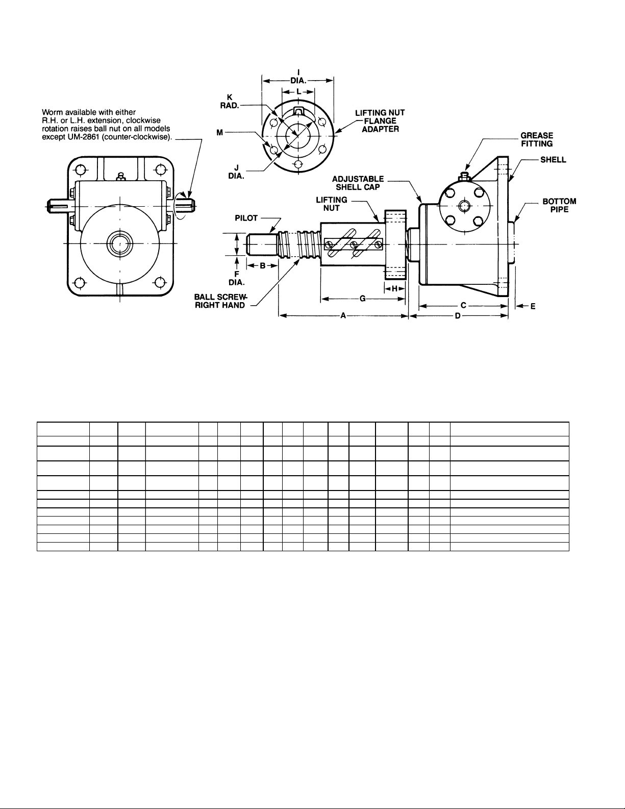
1-4. Dimensions
g
Note: Ball nut must be kept from rotating to prevent it
from self-lowering.
Worm and gear set is not self-locking.
Use brake on worm shaft or motor.
Housing dimensions and base configurations vary.
Table 3. Upright Models
Drawing
Model Number
UM-28632 1/2 TON 28631 RAISE + 2 5/ 8 2 3 /8 C 0 .437 1.740 .530 2.600 1˝ Sq. .797 .822 4 Holes - 17/64 Dia. On 2 3/32 Dia. B.C.
UM-9803 &
KUM-2803
UM-98031*
KUM-28031*
UM98004 &
KUM-28004
UM-9806 5 TON 9805 RAISE + 4 5/8 1 5 1/4 C 0 1.000 4.333 .895 4 15/16 2.625 1.690 1.981 4 Holes - 17/32 Dia. On 4 1/16 Dia. B.C.
UM-98061* 5 TON 9805 RAISE + 4 1 5 1/4 C 0 1.000 3.648 1.020 4 15/16 2.625 1.720 1.718 4 Holes - 17/32 Dia. On 4 1/8 Dia. B.C.
UM-9811 10 TON 9810 RAISE + 6 1 5 5/8 C 0 1.000 4.333 .895 4 15/16 2.625 1.690 1.981 4 Holes - 17/32 Dia. On 4 1/16 Dia. B.C.
UM-98111* 10 TON 9810 RAISE + 5 1 5 5/8 C 0 1.000 3.648 1.020 4 15/16 2.625 1.720 1.718 4 Holes - 17/32 Dia. On 4 1/8 Dia. B.C.
AUM-9821 20 TON 9820 RAISE + 8 2 1/ 2 7 1/8 8 1/8 1 3/4 1.750 6.706 1.582 5 3/8 3.375 2.272 2.561 6 Holes - 21/32 Dia. On 4 3/8 Dia. B.C.
UM-9826 25 TON 9825 RAISE + 10 2 1/4 8 7/8 10 1/2 2 2.250 9.395 2.020 7 3/8 4.751 3.076 3.349 8 Holes - 25/32 Dia. On 6 1/4 Dia. B.C.
UM-2861* 50 TON 2860 RAISE + 15 3 1/4 10 7/8 1 2 3/ 4 3.250 12.625 2.020 9 3/4 5.880 3.756 4.029 6 Holes - 1 1/32 Dia. On 8 Dia. B.C.
Ratin
2 TON
2 TON
3 TON 28003 RAISE + 3 3/4 1 1/8 4 1/16 4 1/2 0 .750 3.395 .832 4 15/16 2.125 1.386 1.587 4 Holes - 25/64 Dia. On 3 7/16 Dia. B.C.
*1˝ Lead Screw Models
Note: Dimensions are subject to change without notice.
All dimensions in inches unless otherwise specified.
Ref.
9802 &
2802
9802 &
2802
ABCD EFGH I J KL M
RAISE + 3 1/16 1 1/8 4 1/16 C 0 .750 2.377 .630 3 1/4 1.500 Sq. 1.194 1.104 4 Holes - 17/64 Dia. On 2 3/4 Dia. B.C.
RAISE + 3 11/16 1 1/8 4 1/16 C 0 .750 3.030 .630 4 13/64 1.500 Sq. 1.194 1.104 4 Holes - 17/64 Dia. On 2 3/4 Dia. B.C.
4
Page 5
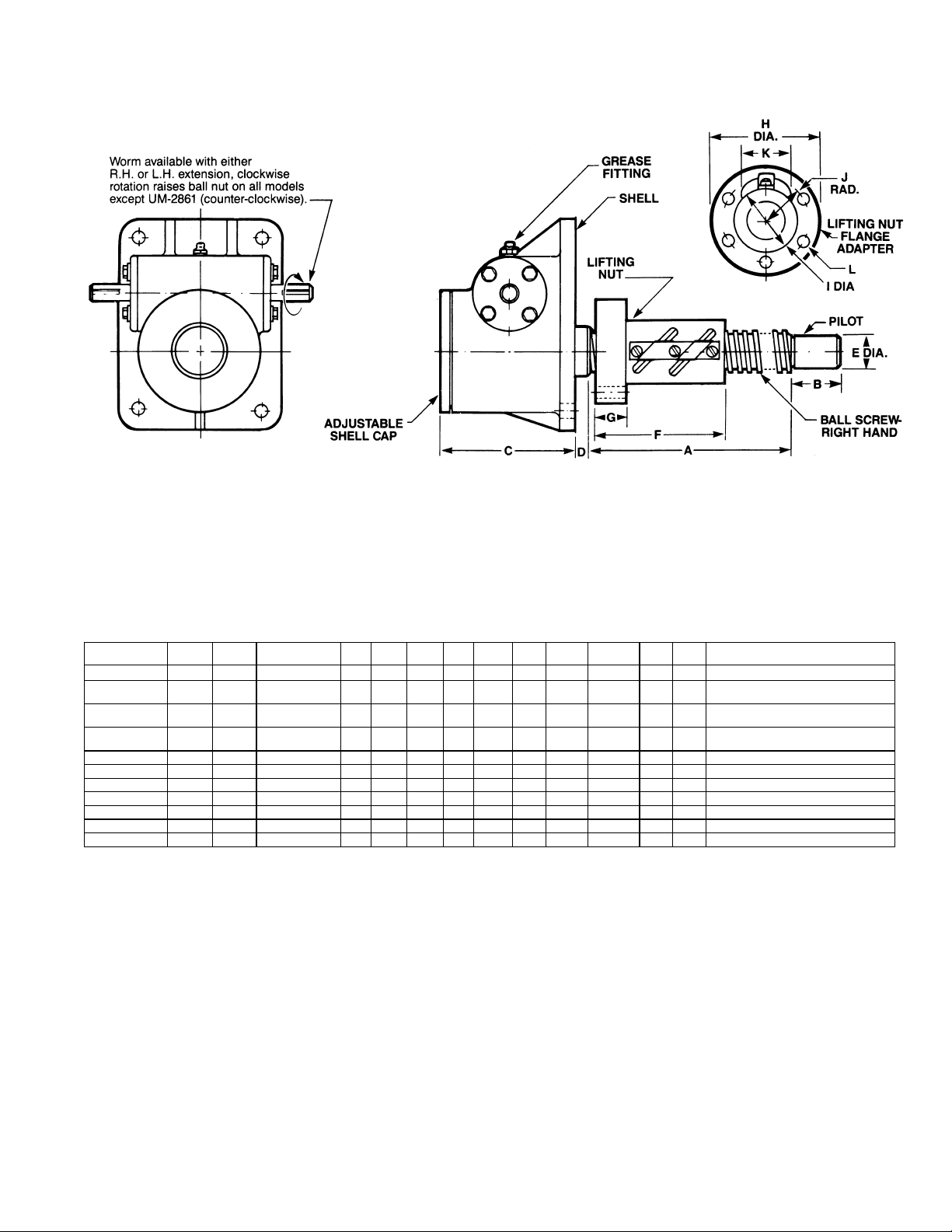
1-4. Dimensions (cont.)
g
Note: Ball nut must be kept from rotating to prevent it
from self-lowering.
Worm and gear set is not self-locking.
Use brake on worm shaft or motor.
Housing dimensions and base configurations vary.
Table 4. Inverted Models
Model Number
DM-28632 1/2 TON 28631 RAISE + 2 5/ 8 2 3/8 3 /8 .437 1.740 .530 2.600 1˝ Sq. .797 .822 4 Holes - 17/64 Dia. On 2 3/32 Dia. B.C.
DM-9803 &
KDM-2803
DM-98031*
KDM-28031*
DM98004 &
KDM-28004
DM-9806 5 TON 9805 RAISE + 4 5/8 1 5 1/4 3 /4 1.000 4.333 .895 4 15/16 2.625 1.690 1.981 4 Holes - 17/32 Dia. On 4 1/16 Dia. B.C.
DM-98061* 5 TON 9805 RAISE + 4 1 5 1/4 3 /4 1.000 3.648 1.020 4 15/16 2.625 1.720 1.718 4 Holes - 17/32 Dia. On 4 1/8 Dia. B.C.
DM-9811 10 TON 9810 RAISE + 6 1 5 1 1/8 1.000 4.333 .895 4 15/16 2.625 1.690 1.981 4 Holes - 17/32 Dia. On 4 1/16 Dia. B.C.
DM-98111* 10 TON 9810 RAISE + 5 1 5 1 1/8 1.000 3.648 1.020 4 15/16 2.625 1.720 1.718 4 Holes - 17/32 Dia. On 4 1/8 Dia. B.C.
ADM-9821 20 TON 9820 RAISE + 8 2 1/2 7 1/8 1 5/8 1.750 6.706 1.582 5 3/8 3.375 2.272 2.561 6 Holes - 21/32 Dia. On 4 3/8 Dia. B.C.
DM-9826 25 TON 9825 RAISE + 10 2 1/4 8 7/8 2 1/2 2.250 9.395 2.020 7 3/8 4.751 3.076 3.349 8 Holes - 25/32 Dia. On 6 1/4 Dia. B.C.
DM-2861* 50 TON 2860 RAISE + 15 3 1/4 11 2 1/2 3.250 12.625 2.020 9 3/4 5.880 3.756 4.029 6 Holes - 1 1/32 Dia. On 8 Dia. B.C.
*1˝ Lead Screw Models
Note: Dimensions are subject to change without notice.
All dimensions in inches unless otherwise specified.
Drawing
Ratin
2 TON
2 TON
3 TON 28003 RAISE + 3 3/4 1 1/8 3 3/4 1 .750 3.395 .832 4 15/16 2.125 1.386 1.587 4 Holes - 25/64 Dia. On 3 7/16 Dia. B.C.
Ref.
9802 &
2802
9802 &
2802
ABCD EFGHIJK L
RAISE + 3 1 1/8 3 3/4 5/ 8 .750 2.377 .630 3 1/4 1.500 Sq. 1.194 1.104 4 Holes - 17/64 Dia. On 2 3/4 Dia. B.C.
RAISE + 3 5/8 1 1/8 3 3/4 5 /8 .750 3.030 .630 4 13/64 1.500 Sq. 1.194 1.104 4 Holes - 17/64 Dia. On 2 3/4 Dia. B.C.
5
Page 6

1-5. Important Precautions
In order to ensure that actuators provide good
service over a period of years, the following precautions should be taken:
1. Select an actuator that has a rated capacity
greater than the maximum load that may be
imposed on it.
2. The structure on which the actuators are
mounted should have ample strength to carry
the maximum load, and should be rigid enough
to prevent undue deflection or distortion of the
actuator supporting members.
3. It is essential that the actuators be carefully
aligned during installation so that the lifting
screws are perfectly plumb and the connecting
shafts are exactly in line with the worm shafts.
After the actuators, shafting, gear boxes, etc.,
are coupled together, it should be possible to
turn the main drive shaft by hand. If there are no
signs of binding or misalignment, the actuator
system is then ready for normal operation.
4. The actuators should have a greater raise than
is needed in the actual installation. Should it be
necessary to operate the actuators to the extreme limits of travel, it should be done cautiously.
Caution
Do not allow actuator lifting nut travel to go
beyond catalog closed height (A) of actuator
or serious damage to lifting nut or the internal actuator mechanism may result. Refer to
table of specifications (par. 1-3) for closed
height (A) of respective units.
5. The worm shaft speed for these actuators
should not exceed 900 RPM for heavy loads, or
1800 RPM for light loads of one-fourth (or less)
of the actuator capacity.
6. The lifting screw should not be permitted to
accumulate dust and grit on the threads. If
possible, screws should be protected by some
means such as a boot.
7. The ball screw and lifting nut should be checked
periodically for excessive backlash and spalling
of race ways.
8. The lubrication procedures for normal and
severe service conditions, as described in
Section II, paragraph 2-1, should be closely
followed.
9. Due to high efficiency of Ball Screw actuators, a
brake must be used in conjunction with the
motor selected for actuator positioning (refer to
current catalog for brake selection data).
1-6. Warranty and Warranty Repair
Subject to the conditions stated herein, Duff-
Norton will repair or replace, without charge, any
parts proven to Duff-Norton’s satisfaction to have
been defective in material or workmanship. Claims
must be made within one year after date of shipment. Duff-Norton will not repair or replace any
parts that become inoperative because of improper
maintenance, eccentric loading, overloading, chemical or abrasive action excessive heat, or other
abuse
Equipment and accessories not of Duff-Norton’s
manufacture are warranted only to the extent that
they are warranted by the manufacturer, and only if
the claimed defect arose during normal use, applications and service. Equipment which has been
altered or modified by anyone without Duff-Norton’s
authorization is not warranted by Duff-Norton.
EXCEPT AS STATED HEREIN, DUFF-NORTON
MAKES NO OTHER WARRANTIES, EXPRESS OR
IMPLIED, INCLUDING WARRANTIES OF MERCHANTABILITY AND FITNESS FOR A PARTICULAR PURPOSE.
If you have any questions concerning warranty
repair, the Duff-Norton Company.
Authorization for return must be received from
the Duff-Norton Company before returning any
equipment for inspection or warranty repair.
6
Page 7

Section II
2-1. Lubrication
Maintenance
Unless otherwise specified, actuators are
shipped packed with grease which should be sufficient for one month of normal operation. For normal
operation the actuator should be lubricated once a
month, using Extreme Pressure grease Shell Oil Co.
Shell Albida LC EP #2 (Shell Product Code 70311).
This grease has been thoroughly evaluated in
Duff-Norton actuators and has demonstrated superior lubricating properties affecting both wear life
and maximum duty cycle. Duff-Norton is not aware
of an equivalent grease. If this grease is not
available in your area please contact your local
supplier for their recommendations. Greases containing molybdenum disulfide should never be used.
For severe service conditions, the actuators
should be lubricated more frequently using the
above grease (daily to weekly depending on conditions). If duty is heavy, an automatic lubrication
system is strongly recommended.
For most applications periodically lubricate the
rotating ball screws with a cloth dampened with a
good grade 10W30 oil. An instrument grade oil
should be used in dirty and heavy dust environments, while bearing grease is recommended for
operating environments at extremely high temperatures. Extremes of temperature and other environmental conditions should be referred to Duff-Norton
for recommended lubrication procedures.
Caution
Where the screw is not protected from
airborne dirt, dust, etc., do not leave a heavy
film of lubricant on the screw. Keep the ball
screw barely damp with the lubricant. Inspect at
regular intervals to be certain a lubricating film
is present. Ball screws should never be run dry.
2-2. Rebuild Procedure
Duff-Norton recommends the following procedures for assembly and disassembly of actuators.
1. Tag critical parts to facilitate reassembly.
2. Mark all mating surfaces to ensure proper
meshing.
3. Clean and lubricate all parts as required.
4. All seals must be replaced when rebuilding.
5. All screws, washers and other small common
parts must be replaced if damaged in any way.
6. Replace damaged or frozen lubrication fittings
with new ones.
2-3. Required Tools
A bearing puller and press, soft jaw table clamp
and common hand tools are necessary for proper
assembly and disassembly.
2-4. Disassembly
Refer to Figure 3-1. When a numerical index
number is referred to, the reference is to Figure 3-1.
Note
Disassembly should be accomplished on a clean
cloth.
1. Disassembly Inspection (Refer to Figure 3-1). To
determine the need for replacement of the ball
screw (5) or the lifting nut (24) the following
inspection should be made prior to disassembly
of the lifting nut from the ball screw: Inspect the
lifting nut assembly (24) and ball screw (5) as
follows:
a. Lubricate the lifting nut assembly and ball
screw . See paragraph 2-1.
b. Inspect the ball screw grooves for signs of
excessive wear, pitting, gouges, corrosions,
spalling or brinelling. It is usually less expensive to replace the ball screw when any of
the above conditions exist. If you feel, however, that it can be reworked, return it to
Duff-Norton for final evaluation.
c. If none of the above conditions exist, check
backlash. Secure the ball screw in a table
clamp or similar fixture. Make sure that the
screw shaft cannot rotate. Push firmly on the
lifting nut assembly, first in one direction and
then in the opposite direction. This axial
movement of the lifting nut assembly is the
backlash. While making sure that neither
member rotates, measure the backlash with
a dial indicator.
Note
Measure backlash at points of maximum
usage. Backlash of .001˝ to .010˝ is acceptable.
d. If the backlash is over .010˝ and the ball
screw appears usable, replace ball nut.
2. Disassembly of Lifting Nut (24) From Ball Screw
(5) (Refer to Figure 2-2).
a. Refer to Table 2-1 and select a tubular arbor
with an I.D. slightly larger than the screw
pilot diameter. The arbor O.D. should allow it
to slide into the lifting nut between the screw
and the bearing balls. The arbor should be
7
Page 8

long enough to extend 1 1/2˝ to 2˝ beyond
each end of the lifting nut.
Note
Apply tape to arbor O.D. at end away from ball
screw pilot to prevent lifting nut from accidentally
running off of arbor during disassembly (an O-ring
with a large cross section, stretched over the arbor,
is ideal for this purpose.)
6. Remove ball screw (5) and gear assembly (6)
from shell. For ease in removing ball screw and
gear assembly, loosen cap screws (9) holding
flanges (11) and shift worm (14) slightly.
Note
On some models it may be necessary to remove
worm before moving ball screw and gear assembly (see Step 7 and 8).
Table 2-1. Dimensions Ball Nut Storage Arbor
Actuator
Model No.
28632 .480 .500
9803 2803 .820 .889
98031 28031 .820 .889
28004/98004 .870 .889
9806 1.140 1.156
9811 1.140 1.156
98111 1.140 1.156
9821 1.850 1.884
9826 2.480 2.500
2861 3.338 3.366
b. Holding arbor firmly against shoulder of ball
screw pilot (5), unthread lifting nut (24) from
ball screw (5). As lifting nut bearing balls
disengage from ball screw grooves (5),
center lifting nut on arbor and remove arbor
from ball screw pilot.
Lift arbor and lifting nut together, holding in
place to prevent lifting nut from sliding off of arbor.
c. Pass binding wire through arbor and bind
lifting nut and arbor together.
Keeping assembly together in this manner will
eliminate the need for complete assembly of the
lifting nut during reassembly go the actuator. Complete actuator disassembly as follows:
4. Remove pipe (4) from shell (3) [upright units] or
from shell cap (2) [inverted units].
Some models have an expansion plug (4a) in
place of pipe (4). If the expansion plug must be
replaced, it will be removed later per Step 18.
5. Remove set screw (10 from shell cap (2) and
remove shell cap from shell (3).
It may be necessary to tap shell (2) with a
hammer to loosen shell cap.
Ball Screw
Root Dia. (in) Arbor O.D. (in)
Note
Note
Note
Note
7. Remove top bearing (7) which may be attached
to either shell cap (2) or worm gear assembly
(6).
8. Remove cap screws (9), lockwashers (10) and
flanges (11).
Note
Be careful not to lose flange shims (12).
For 1/2-ton Models - Remove four set screws
(9a) from shell (3) and unthread bushings (11a)
from shell.
9. Remove worm (14) and worm bearings (15)
from shell (3) by striking end of worm shaft with
a soft-head mallet or hammer.
For 1/2-Ton Model - Remove worm (14) with needle
bearings (15a) and races (15b) from shell (3)
and remove needle bearings and races from
worm.
10. Remove bottom load bearings (8) which may be
attached to either shell (3) or gear (6).
11. Press oil seals (13) out of flanges (11).
12. Remove bearings (15) from worm (14) with
puller or press.
Note
This step is not necessary if worm (14) or
bearings (15) are not damaged.
13. Remove set screw (21) from locknut (20).
Note
Some models may not utilize a set screw.
14. Restraining ball screw (5) from turning (use soft
jaws), remove locknut (20) from ball screw (5).
Note
If all parts are to be reused, match-mark end of
screw and locknut so that they can be reassembled in the same order.
15. Remove worm gear (6) from ball screw (5).
Note
It may be necessary to tap on worm gear assembly to remove it. Use a soft face hammer.
Do not tap on gear teeth.
8
Page 9

Figure 2-2. Ball Nut Storage Arbor
16. Remove key (22) from ball screw (5).
17. Remove spacer (23) from ball screw.
Note
On some models spacer is threaded.
Note
Some models do not have a spacer.
18. Inverted Models - Remove guide bushing (16)
from shell (3).
19. For units with an expansion plug (4a) in shell (3)
or shell cap (2), damaged plugs must be removed. Drive or press plug out of shell or shell
cap with a large diameter punch (1˝).
Disassembly is now complete.
2-5. Cleaning
1. Use degreasing solvent to remove dirt, grease
or oil from all parts. Be sure to flush the lifting
nut assembly (24) thoroughly while running the
assembly over the arbor several times.
Warning
Provide adequate ventilation during the use
of cleaning agents; avoid prolonged breathing of fumes and contact with skin.
2. Use clean hot water or a soap solution for
general cleaning of painted surfaces.
3. Dry parts thoroughly after cleaning.
Note
Before installing new parts, remove any rust
preventive, protection grease, etc.
on their working or mating surfaces.
3. Check small common components (screws, etc.)
and replace as required.
4. Check bearings (7), (8), and (15) for seizure,
galling or play and replace as required.
2-7. Assembly
1. Refer to Figure 2-3 for replacement of expansion
plug (4a) in shell (3) for upright units or shell cap
(2) for inverted units.
a. Set shell cap (2) [inverted models] or shell
(3) [upright models] over a steel bar which is
approximately 1/8˝ to 3/16˝ shorter in height
than the shell or shell cap. The diameter of
the bar should be close to the I.D. of the
shell or shell cap.
b. Place expansion plug (4a) on the bar (con-
cave surface down) and flatten against the
bar with a large diameter punch or press
making sure that the plug is flattened
throughout its entire diameter.
2. For units with tapered roller load bearings, press
bearing cones onto worm gear (6) with small
end of cones away from gear face. Be sure that
cones are seated properly against gear shoulder.
3. Assembly spacer (23) on ball screw (5).
Note
On models with threaded spacers, make sure
that spacer is tightly threaded against ball screw
shoulder.
2-6. Inspection
1. Make a visual inspection of shell (3) for broken,
cracked or distorted areas. Check threads of all
bores for burrs or broken threads.
2. Check shell cap (2), bottom pipe (4), worm gear
assembly and flanges (11) for burrs or scratches
Note
Some models do not have a spacer.
4. Insert key (22) in ball screw (5).
5. Assemble worm gear (6) on ball screw (5). For
counterbored worm gears, face counterbore
9
Page 10

away from ball screw threads.
6. Thread locknut (20) on ball screw (5) and tighten
securely against worm gear (6). Make certain
that this assembly is tightly drawn up.
Note
On some locknuts the tapped set screw hole is
not centered. In this case assemble the locknut
with the tapped hole farthest away from the
worm gear face.
7. Install set screw (21) in locknut (20) locking the
nut in place (some models do not utilize a set
screw).
Note
If new parts have been installed it may be
necessary to respot holes fro set screws.
8. Press worm bearings (15) on worm (14) making
sure that bearings are seated properly against
worm shoulder.
Note
When tapered roller bearings are used, the
small end of the cones should point to the end of
the worm shaft.
9. Inverted units only - Install guide bushing (16) in
shell (3). Guide bushings must be flush with
base. With a center punch, lock guide bushing in
place by peening on thread O.D. of bushing and
shell.
10. Install bottom load bearing (8) in shell (3).
Note
For actuators with tapered roller load bearings,
install bearing cup.
11. Install worm (14) and bearing (bearing cone)
assembly (15) in shell. For units with tapered
roller worm bearings, installed bearing cups in
shell.
For 1/2-ton Models - Slide thrust race (15b),
needle bearing (15a) and second thrust race
(15b) on each end of worm (14) and position
worm in shell (3).
Note
For some units it is easier to assemble worm
(14) and bearing assembly (15) after worm gear
(6) is in place. See Step 11.
12. Press oil seals (13) in flanges (11).
Note
The sealing element of the seal should face
inward. Seals are not required on 1/2-ton models.
13. Assemble worm flanges (11) with shims (12) and
bolt in place with cap screws (9) and
10
lockwashers (10). Care should be taken to
prevent cutting of seal on worm keyway.
For 1/2-Ton Models - Slide bushings (11a) over
each end of worm shaft (14) and thread bushings into shell (3) until they are positioned to
control lateral movement of worm to within .002
inches. Bushings should be equally threaded
into each end of shell. Lock bushings in place
with set screws (9a).
Note
If new parts have been installed, lightly spot-drill
bushings prior to locking in place with set
screws.
14. Install ball screw (5) and worm gear assembly
(6).
Note
For some units it is easier to install worm and
bearing assembly after worm gear (6) and ball
screw (5) assembly are in place. See Step 11.
Note
After worm, worm gear and ball screw assembly
are in place and flanges (11) are assembled,
strike each end or worm shaft sharply with a soft
face hammer to seat bearing properly. Recheck
flange bolts for tightness. Worm should turn
freely with minimum drag and end play. If too
much end play is present, remove shims as
required. If worm does not turn freely, add shims
as required.
15. Assemble top load bearing (7) on worm gear (6).
Note
For units with tapered load bearings, install
bearing cup in shell cap (2).
16. Fill shell (3) approximately one half full of grease
and install grease fitting (17).
17. Install shell cap (2) and screw down tight.
Note
Shell cap flange does not necessarily have to
bear against top of shell, there will usually be a
gap. This will put a light drag on worm. If worm
is hard to turn, back off slightly on shell cap.
18. Install set screws (1) in shell cap (2). Tap shell
cap sharply with hammer and re-tighten set
screw.
Note
If new parts have been installed, it may be
necessary to respot holes for these screws.
19. All models except those with expansion plugs Install pipe (4) in shell (3) for upright models or
in shell cap (2) for inverted models.
Page 11

20. Refer to Figure 2-2 for reassembly of lifting nut
(24) from tube arbor to ball screw (5).
a. With lifting nut centered on arbor tube, grasp
lifting nut and arbor to prevent lifting nut from
running off of arbor, and remove binding
wire.
b. Position arbor over ball screw (5) pilot.
Note
Flange of lifting nut should face toward
actuator shell and away from ball screw pilot.
c. Gently slide lifting nut (24) down arbor and
thread it onto ball screw (5). After lifting nut
is completely threaded onto ball screw,
remove arbor from ball screw pilot.
Note
Wrap tape around ball screw threads (below
pilot and above lifting nut ) to prevent lifting nut
from running off of ball screw during installation
of unit.
21. Manually operate actuator to insure proper
functioning of all components prior to use.
Assembly is now complete.
Figure 2-3. Expansion Plug Replacement
11
Page 12

y
p
Section III
Illustrated Parts List
3-1. General
This section contains an exploded illustration of
the 2800 and 9800 Series rotating ball screw actuators. The number adjacent to each part on the
3-2. Parts List for 2800 and 9800 Series Rotating Ball Screw Actuators
Index
No.
1 Screw, Set (Shell Cap) 2 13 Seal, Oil 2
2 Shell Cap 1 14 Worm 1
3 Shell, Actuator 1 15 Bearing, Worm 2
4 Pipe, Bottom 1 15a Bearing, Needle (1/2-ton model) 2
4a Plug, Expansion 1 15b Washer, Thrust (1/2-ton model) 4
5 Ball Screw 1 16 Bushing, Guide
6 Worm Gear 1 (Inverted Models Only) 1
7 Bearing, Top Load 1 17 Fitting, Grease 1
8 Bearing, Bottom Load 1 18 Nameplate 1
9 Screw, Cap 8 19 Screws, Drive 2
9a Screws, Set (1/2-ton model) 4 20 Nut, Lock 1
10 Washer, Lock 8 21 Screw, Set (Locknut) 1
11 Flange, Worm 2 2 2 Key 1
11a Bushing, Worm (1/2-ton model) 2 23 S
12 Shim, Flange 2 24 Lifting Nut 1
When ordering spare parts be sure to include:
1. The nameplate model number of your actuator.
2. Index number and name of part.
Part Name Qty Req.
illustration is the index number. Keyed to this index
number on the parts list is the part name
Index No.
acer 1
Part Name Qt
Req.
12
Page 13

A
Figure 3-1. Exploded Illustration 2800 and 9800 Series Ball Screw Actuators
13
Page 14

14
Page 15

15
Page 16

© 2000 Yale Industrial Products, Inc.
P.O. Box 7010
Charlotte, NC 28241-7010
General Office (704) 588-0510
Customer Service (800) 477-5002
Customer Service (704) 588-4610
FAX (704) 588-1994
Email: duffnorton@cmworks.com
www.duffnorton.com
®
SK-2373-R
500/1002
 Loading...