

Duff-Norton 528AMJ, 126AMJ, 536AMJ, 528CMJ, 144AMJ Operating And Maintenance Instructions With Parts
...


Table of Contents
Section I Introduction
1-1. General
1-2. Construction
1-3. Technical Specifications and Operational Characteristics
TABLE 1-1. Technical Specifications
TABLE 1-2. Operational Characteristics
Section II Inspection, Testing, and Maintenance
2-1. Inspection
2-2. Inspection Classification
2-3. Initial Inspection
2-4. Frequent Inspection
FIGURE 2-1. Inspector's Report
TABLE 2-1. Minimum Inspection Schedule
2-5. Periodic Inspection
2-6. Special Inspection Requirements
FIGURE 2-2. Lifting Nut Inspection
2-7. Load T est
2-8. Maintenance
2-9. Lubrication
FIGURE 2-3. Throttle Adjustment
Section III Operation
3-1. Operational Requirement
3-2. Operating Procedures and Precautions
Section IV Illustrated Parts List
4-1. General
List of Illustrations
FIGURE 4-1. Exploded Illustration of 528AMJ and 536AMJ Jacks
FIGURE 4-2. Exploded Illustration of Gage Area
Parts Breakdown for 528AMJ and 536AMJ Jacks
FIGURE 4-3. Exploded Illustration of 528CMJ and 536CMJ Jacks
FIGURE 4-4. Exploded Illustration of Gage Area
Parts Breakdown for 528CMJ and 536CMJ Jacks
FIGURE 4-5. Exploded Illustration of 126AMJ, 132AMJ, and 144AMJ Jacks
FIGURE 4-6. Exploded Illustration of Gage Area
Parts Breakdown for 126AMJ, 132AMJ, and 144AMJ Jacks
FIGURE 4-7. Exploded Illustration of 126CMJ, 132CMJ, and 144CMJ Jacks
FIGURE 4-8. Exploded Illustration of Gage Area
Parts Breakdown of 126CMJ, 132CMJ, and 144CMJ Jacks
FIGURE 4-9. Exploded Illustration of X6000 Air Motor
Parts Breakdown of X6000 Air Motor
FIGURE 4-10. Exploded Illustration of X4153 Air Motor
Parts Breakdown of X4153 Air Motor
Table of Contents
1
1
1
1
2
22222
3345566
6
6
7
777
888
10
11
12-15
16
17
18-21
22
23
23-27
28
29
29-33
353637
38
Subject to the condition stated herein, Du Norton Air Motor Jack Co. will repair or replace, without charge, any parts proved to our satisfaction to have been defective in material
1. Units or any parts that become inoperative because of improper maintenance, eccentric loading, overloading, chemical or abrasive action, excessive heat, or other abuse.
3. Equipment and accessories not of DNAMJ Co.'s manufacture are warranted only to the extent of the original manufacturer's warranty and subject to the same conditions as
4. Except as stated herein, DNAMJ Co. makes no other warranties, expressed or implied, including warranties of merchantability and tness for a particular purpose.
or workmanship. Claims must be made within one year aer the date of shipment.
2. Equipment which has been altered or modied by anyone without DNAMJ Co.'s authorization.
stated above regarding improper maintenance, abuse, overloading, etc.
Du Norton Air Motor Jack Warranty Policy
e warranty is null and void for:

Introduction
1-1. General
a. This manual provides instructions for
operating, inspection, testing, and
maintenance, as well as an illustrated
parts list for the following Duff Norton
Air Motor Jacks:
528AMJ 528CMJ
536AMJ 536CMJ
126AMJ 126CMJ
132AMJ 132CMJ
144AMJ 144CMJ
b. This publication is written in accordance
with standards set forth in the current
ANSI B30.1. To ensure reliable and
long, satisfactory use of the air motor
jacks, the instructions contained in this
publication should be closely followed.
Safety precautions to protect against
accidental injury or property damage
should be observed at all times while
using the jacks. All personnel
concerned with the installation,
operation, inspection, and maintenance
of the jacks are urged to read the
American National Standard (ANSI
B30.1). That standard contains
important rules (some mandatory and
some of an advisory nature) designed to
prevent or minimize injury or otherwise
protect life, limp, and property. You
should especially be aware of the
mandatory rules pertaining to inspection
Section I
requirements and advisability of
maintaining written, dated, and signed
inspection reports and records.
NOTE
The air motor jacks are recommended for
general industrial use.
1-2. Construction
The Duff Norton Air Motor Jack
consists of a cast shell, a lifting mechanism
made up of gears, bearings, shafts, & pinions,
and a lifting screw. These jacks are driven by an
air motor and require a source of compressed air
for operation. Carrying handles, wheels, and
trundle handle for transporting and positioning
the jacks are provided.
1-3. Technical Specifications and
Operational Characteristics
a. The user should be aware of the
capabilities of air motor jack s, e sp e c ially load
capacity.
WARNING
Overloading can be hazardous to the jack,
operating personnel, and the load in the event
of jack failure.
b. See Table 1-1 for technical
specifications of the jacks.
c. See Table 1-2 for operational
characteristics for the jacks.
1
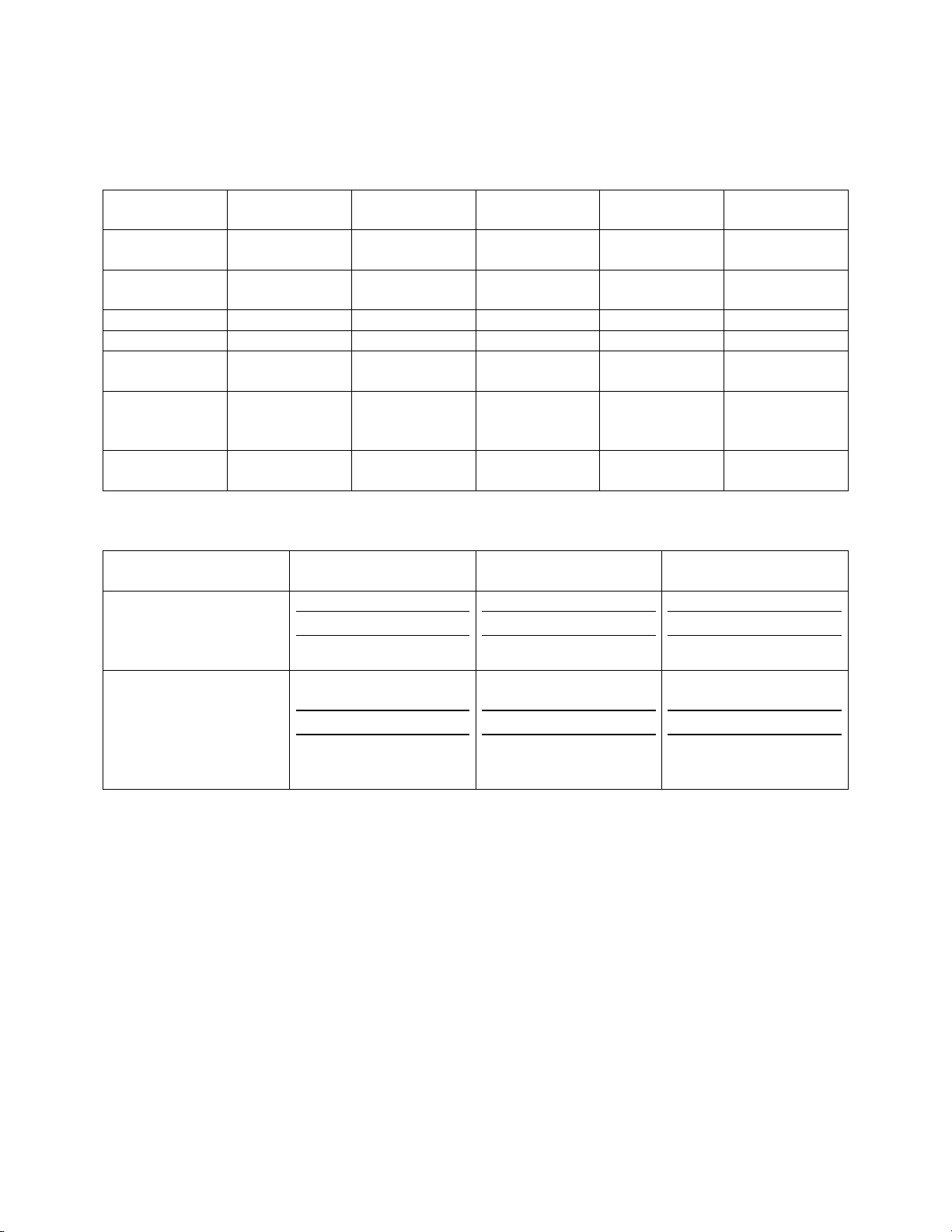
TABLE 1-1. TECHNICAL SPECIFICATIONS
528AMJ
528CMJ
Sustaining
Capacity, Tons
Lifting
Capacity, Tons
Height, Inches 28 36 26 32 44
Raise, Inches 17 25 13 ¾ 18 30
Base Diameter,
Inches
Head
Diameter,
Inches
Weight,
Pounds
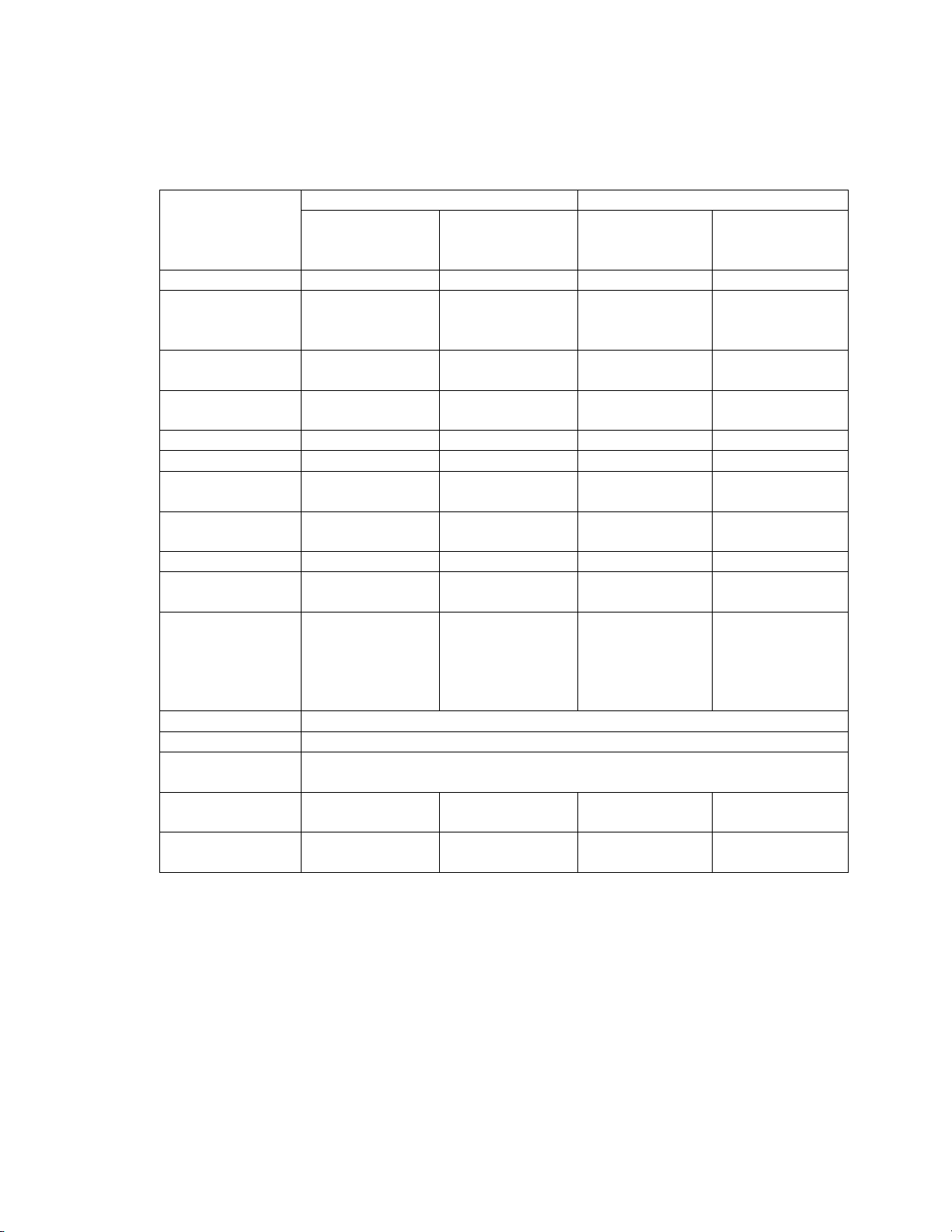
Jack Load (Tons) Average Rate* of Rise
528AMJ
528CMJ
536AMJ
536CMJ
126AMJ
126CMJ
132AMJ
132CMJ
144AMJ
144CMJ
*Values are for jacks supplied with air of 100 psi dynamic air pressure at the air valve entrance
2-1. Inspection
The inspection classifications herein are
minimum requirements and should be
augmented when experience from operating
conditions indicate. See Table 2-1 for minimum
inspection schedule.
2-2. Inspection Classification
The jack inspection classific a tio n
consists of initial inspection prior to use and two
50 50 100 100 100
50 50 100 100 100
14 15 13 13 18
5 5 6 1/8 6 1/8 6 1/8
394 425 448 480 530
TABLE 1-2. OPERATIONAL CHARACTERISTICS
536AMJ
536CMJ
0
25
50
0
50
100
Section II
Inspection, Testing, and Maintenance
126AMJ
126CMJ
(in./min.)
11.2
7.1
2.6
6.0
3.2
2.2
general classifications designated as Frequent
Inspection and Periodic Inspection based upon
the intervals at which inspection should be
performed. The intervals in turn are dependent
upon the nature of the critical components of the
jack and the degree of their exposure to wear,
deterioration or malfunction.
2-3. Initial Inspection
132AMJ
132CMJ
Cu. Ft. of Free* Air
Required Per Minute
144AMJ
144CMJ
190
170
120
200
180
155
2

Any new or repaired jack shall be
carefully inspected prior to in itia l u se . An
inspection shall be made by or under the
direction of a person familiar with air motor jack
operations and industrial safety standards.
a. Check for proper service of grease and
oil (refer to paragraph 2-9).
b. Make a detailed external inspection for
proper assembly. Check for any loose
or missing parts, such as cotter pins,
springs, or washers. Remove from
service any jack incorrectly assembled
or with missing parts.
c. Operate the jack through at least one
lifting and lowering cycle while
observing lifting-mechanism operation.
Remove from service any jack which
shows evidence of erratic operation.
FIGURE 2-1. INSPECTOR’S REPORT
Item Remarks (List Deficiencies and Recommended Action
Inspector’s Date Approved Date
Signature Inspected By
d. Perform load test in accordance with
paragraph 2-7.
2-4. Frequent Inspection
Visual examination by the operator or
other qualified designated personnel with
records not required.
a. Normal service—one month
b. Severe service—before each use or
daily, whichever is less frequent.
3
Scored or
damaged control
Lubrication (refer
Scored or
Loose bolts or
Damaged or
Air Screen X X
rod
to para 2-9)
Cracked or
damaged housing
Damaged threads X X
Leaking oil X X
damaged standard
Improper
functioning
Damaged top X X
rivets
improperly
assembled
accessory
equipment
Motor blades As per Paragraph 2-6.a
Lifting Nut As per Paragraph 2-6.b
Periodic
Inspection
Same as Frequent
Inspection
Disassemble and
check for wear
Any unsafe condition disclosed by the
inspection shall be corrected before operation
of the jack is resumed. Repairs should be
performed only by designated qualified
personnel.
TABLE 2-1. MINIMUM INSPECTION SCHEDULE
Normal Service Severe Service
Minimum
Inspection
Schedule
*By Operator or designated personnel without records
**By appointed person making records of apparent external conditions to provide the basis
for continuing evaluation
***Or daily, whichever is longer
****If external conditions indicate internal difficulty
CAUTION
Visual
Monthly*
X X
X X
X X
X X
X X
X X
X X
X X
X**** X
Record
Yearly**
c. The following items shall be visually
inspected and observed during operation
for any deficiencies which might appear
between frequent inspections. The
deficiencies listed shall be carefully
examined and determination made
Visual
Before
Use***
Record
Yearly
4

whether or not they constitute a hazard.
If such a determination is made, the jack
shall be removed from service until the
deficiency is corrected.
(1) Check for scored or damaged control
rod.
(2) Check for scored or damaged standard
and keys.
(3) Check for any abnormal conditions,
loose cotter pins, cap screws, and nuts.
(4) Inspect all visible components for
condition and security of all parts.
(5) Check for adequate lubrication. (Refer
to paragraph 2-9).
(6) Check for foreign substance which may
damage or interfere with proper
operation of the jack.
NOTE
A jack that has been idle for one year or
more shall be inspected in accordance with
Frequent Inspection (Table 2-1).
2-5. Periodic Inspection
Visual inspections by designated
qualified personnel, making records of apparent
external conditions, provide the basis for a
continuing evaluation.
a. Normal service—one year
b. Severe service—before each use or
daily, whichever is less frequent, unless external
conditions indicate that disassembly should be
done to permit detailed inspection.
c. Perform inspection in the same manner
as Frequent Inspections, except that records are
kept. A dated and signed inspection record shall
be kept on all Periodic Inspections. See Figure
2-1 for a typical “Inspector’s Record.”
NOTE
It is recommended that the Periodic
Inspection be performed by and Authorized
Warranty Service Center or appropriate trained
authorized individuals.
a. During Periodic Inspection, if extern a l
appearance indicates possible internal difficulty,
the jack shall be disassembled for cleaning and
examination for internal wear or damage.
See Table 2-1 for Minimum Inspection
Schedule.
2-6. Special Inspection Requirements
a. Air motor blades:
Motor blades should be inspected for
wear after each 100 jack lifting cycles. When
blades are worn to a thickness of 25/32 inch or
less, they should be replaced.
b. Lifting Nut:
The jack’s lifting nut should be
inspected for wear after every 100 jack lifting
cycles. In applications where the jack is
exposed to dirt, dust, metal chips, or other
contaminants, the inspection frequency should
be increased.
WARNING
Failure to properly inspect and maintain the
lifting nut could result in a dropped load and
serious worker injury.
To inspect the lifting nut refer to Figures
4-1 through 4-8 and Figure 2-2, and proceed as
follows:
(1) Fully extend the upright unloaded jack.
(2) Loosen the two screws and remove the
gage from the jack.
(3) Clean grease from the hole which had
been covered by the gage.
(4) Insert the slender end of the gage into
the hole.
(5) If the thin tip of the gage can be made to
enter the space between the top flank of the
lifting nut thread and the bottom flank of the
lifting screw thread, the lifting n u t is worn out.
(Refer to Figure 2-2).
(6) Remove jack with worn out lifting nut
from service and ensure that it is properly
repaired before returning to service.
5

Figure 2-2. LIFTING NUT INSPECTION
2-7. Load Test
Any new, altered, or repaired jack shall
be tested for its ability to sustain its rated load
prior to regular use. The jack shall be operated
to 100 percent of its capacity. See Table 1-1 for
applicable load capacity.
2-8. Maintenance
The maintenance of the jack shall
include lubrication, cleaning, and replacement of
defective parts during disassembly and
assembly.
2-9. Lubrication
a. Air motor:
Remove the filler plugs and fill with
Mobil DTE Oil Light (Duff p/n X6002) or
equivalent oil after every eight hours of use. Air
line filter lubrication should be used for this
jack. Rotor ball bearings should be coated with
grease each time the motor is disassembled.
6

b. Weekly lubrication for the jack:
(1) Standard, keys, and shut-off rod. Use a
light oil.
(2) Control valve parts. Use a light oil.
c. Monthly lubrication of the jack:
(1) Lubricate lifting screw through hole in
standard. Use Mobil DTE Oil Light (Duff p/n
X6002).
(2) Clean and lubricate handle latch and
throttle control parts. Use M o b il D TE Oil Light
(Duff p/n X6002).
d. After repair or overhaul:
Drain, flush, and refill internal jack
mechanism with Mobilgrease XHP 461 or
equivalent.
e. Clean and grease wheels regularly.
f. Screw lubrication under heavy load use.
When operating the jack under heavy
loading, pump Mobilgrease XHP 461 grease into
the standard every few jack lifting cycles.
(3) Remove grease level plug and check
grease level. Fill with Mobilgrease XHP 461 or
equivalent.
FIGURE 2-3. THROTTLE ADJUSTMEN T F O R 528A MJ/CMJ, 536AMJ/CMJ, 126AMJ/CMJ,
132AMJ/CMJ, AND 144AMJ/CMJ
Jack is properly adjusted when parts are in position
shown in drawing at left. The head is no less than 3/16
from the top of the shell. The control lever end “F” is
against the end of the stop groove. Pin “D” is against
the end of the throttle lever. Screw “ B ” is in th e h o le
“E” in the control rod.
To make adjustments, loosen lock nuts “A” and “C” and
screw “B.” Then screw control rod in or out of end until
point “F” and pin “D” are in the position shown, with
the head no less than 3/16 from shell. Retighten screw
“B” in hole “E” and lock the nuts “A” and “C.”
SECTION III
OPERATION
3-1. Operational Requirement
a. Operators shall be instructed in the
proper use of the jack.
b. The operator shall familiarize himself
with the jack, its capabilities, and its o p e ra tion .
He/she should also know and understand the
mandatory requirements of American National
Standard (ANSI B30.1).
c. The throttle lever is located o n th e
control valve above the air motor.
(1) To raise a load, pull the throttle le v er to
UP.
(2) To lower a load, push the throttle lever
to DOWN.
(3) To cease movement of a load, place the
throttle lever in the horizontal po s ition .
(4) The throttle lever will automatically
move to the horizontal position when the jack
has extended or lowered to its limit.
3-2. Operating Procedures and
Precautions
The following precautions shall be
followed in operation of the jack:
a. Visually inspect the jack before each
shift or each use, whichever is less frequent.
7
b. Clean any jack exposed to rain, sand, or
grit—then oil before use.
c. Determine if the load is within the load
rating of the jack. Refer to Table 1-1 for load
rating of the jack.
d. Support the jack at the base in such a
manner that it cannot shift under the load.
e. Use shims or constraints to prevent
slippage of base or load.
f. Avoid off-center loading of the jack.
Assure that it is centered, plumbed, and properly
blocked.
g. Do NOT use an extender.
h. Follow the load with cribbing or
blocking.
i. Take measure to prevent personnel from
working or passing under the load until the load
is secured against accidental lowering by
cribbing, blocking, or other means.
j. Ensure that all personnel are clear of the
load before lowering.
k. Ensure that all operators are instructed
as to signals and other procedures for multiple
jacks or other special lifts.
SECTION IV
ILLUSTRATED PARTS LIST
4-1. General
This section contains exploded view
illustrations. The number adjacent to each part
is the index number. Keyed to this index
number on the parts listing is the part name, part
number, and quantity required. When ordering
parts for a particular jack, please specify part
name, part number, quantity desired, and full
jack description, and serial number, if known.
l. Ensure that the lifting nut is ins p e cte d
for wear as per paragraph 2-6.b.
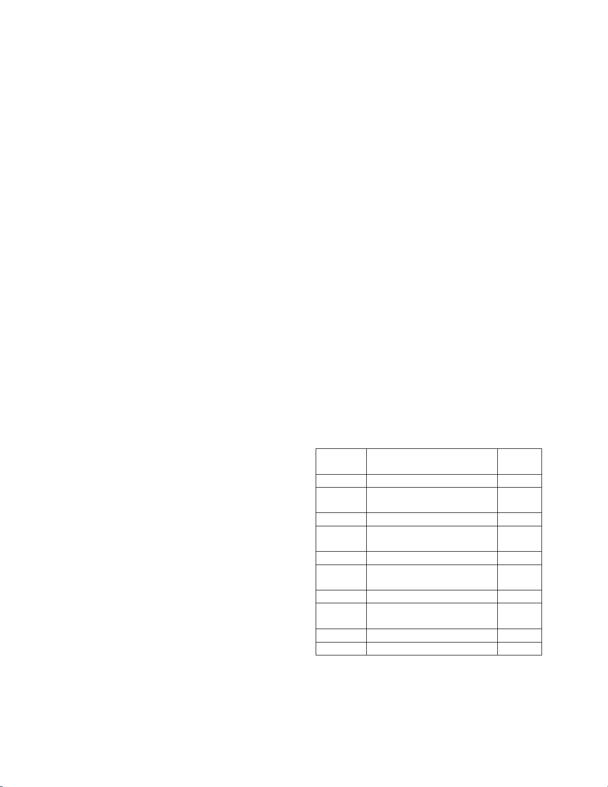
LIST OF ILLUSTRATIONS
Figure
No.
4-1 528AMJ/536AMJ 9
4-2 Gage Area for
4-3 528CMJ/536CMJ 15
4-4 Gage Area for
4-5 126AMJ/132AMJ/144AMJ 21
4-6 Gage Area for
4-7 126CMJ/132CMJ/144CMJ 27
4-8 Gage Area for
4-9 X6000 Air Motor 33
4-10 X4153 Air Motor 35
Jack/Air Motor No. Page
528AMJ/536AMJ
528CMJ/536CMJ
126AMJ/132AMJ/144AMJ
126CMJ/132CMJ/144CMJ
No.
10
16
22
28
8

9

 Loading...