

Ducati SPORTCLASSIC GT 1000 TOURING Owner's Manual

Libretto uso e manutenzione
Owner's manual
Manuel d'utilisation et entretien
Anleitungs-und Instandhaltungsheft

E
Use and maintenance manual

E

E
We would like to welcome you among Ducati enthusiasts,
and congratulate you on your excellent choice of motorcycle.
We are sure that you will use your Ducati for longer journeys
as well as short daily trips, but however you use your
motorcycle, Ducati Motor Holding s.p.a wishes you an
enjoyable ride.
We are continuously working to improve our Technical
Assistance service. For this reason, we recommend that
you follow strictly the instructions in this manual, especially
those regarding the running-in period. In this way, you can
be sure your Ducati motorcycle will continue to be a
pleasure to ride.
For repairs or advice, please contact one of our authorized
Notes
Ducati Motor Holding S.p.A. cannot accept any liability
for errors that may have occurred in the preparation of this
manual. All information in the manual is valid at the time
of going to print. Ducati Motor Holding S.p.A. reserves
the right to make any modifications required due to the
ongoing development of their products.

E
Table of contents
General indications 6
Warranty 6
Symbols 6
Throttle twistgrip 23
Front brake lever
24
Rear brake pedal
25
Gearchange pedal
25
Adjusting the position of the gearchange and rear brake
pedals 26
Main components and devices 28
Position on motorcycle 28
Fuel tank filler cap
29
Seat lock and helmet holder 30
Sidestand
32

E
Adjusting the throttle cable 46
Charging the battery
47
Tensioning the drive chain 49
Lubricating the drive chain 50
Changing light bulbs 51
Front turn signals
53
Rear turn signals
54
Number plate light
55
Brake light 56
Headlight aim
57
Tyres 58
Checking the engine oil level
60
Cleaning and renewing the spark plugs
61
Transmission 72
Frame 73
Wheels 73
Tyres 73
Spark plugs 73
Fuel system 74
Suspension 74
Exhaust system 74
Available colours 74
Electrical system 75
For United States of America Version

E
General indications
Warranty
For your own safety, to ensure the continuing reliability of
Symbols
Ducati Motor Holding S.p.A. advises you to read this manual
carefully so as to become familiar with your motorcycle. If in
doubt, please contact a Ducati Dealer or Authorized Service
Centre. You will find the information in the manual useful on
trips (which Ducati Motor Holding S.p.A. hopes will be
smooth and enjoyable), and it will help you obtain top
performance from your motorcycle for a long time. This
booklet uses a set of symbols with special meanings:
Warning
Failure to comply with these instructions may put

E
Useful road safety information
Warning
Read this section before riding your motorcycle.
Many accidents are the result of the inexperience of the
rider. Always make sure you have your licence with you; you
need a valid licence that entitles you to ride a motorcycle.
Do not lend your motorcycle to persons who are
inexperienced or do not hold a valid licence.
Riders and passengers must always wear appropriate
clothing and a safety helmet.
Be sure you are clearly visible and avoid riding within the
blind spot of a vehicle in front of you.
Be very careful at road junctions, or when riding in areas near
exits from private land or car parks, or on the slip roads to
motorways.
Always turn off the engine when refuelling. Be extremely
careful not to spill fuel on the engine or on the exhaust pipe
when refuelling.
Do not smoke when refuelling.
While refuelling, you may inhale noxious fuel vapours.
Should any fuel drops be spilled on your skin or clothing,
immediately wash with soap and water and change your
clothing.

E
Riding with a full load
Your motorcycle is designed for travelling over long
distances with a full load in complete safety.
Even weight distribution is critical for maintaining safety
standards, and to avoid getting into difficulties when
making sudden manoeuvres or riding on bumpy roads.
Information on load capacity
The total weight of the motorcycle in running order including
rider, passenger, luggage and additional accessories,
should not exceed:
390 kg.
E
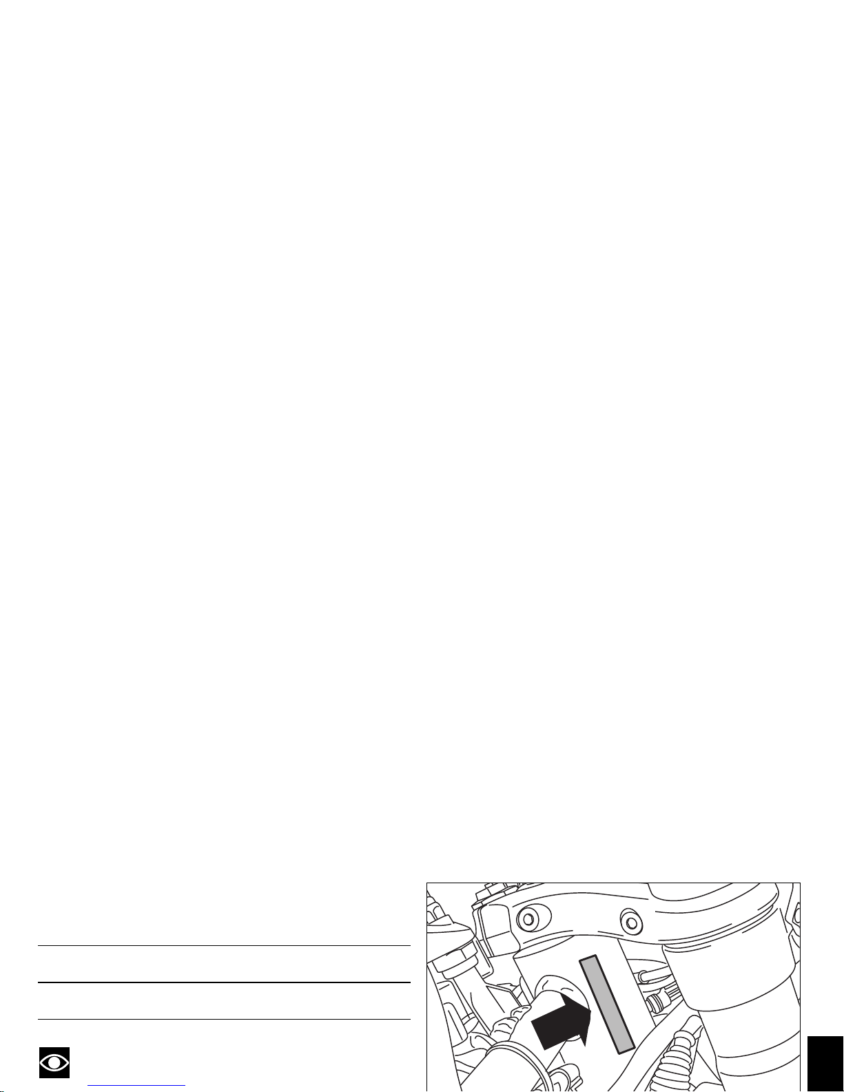
Identification data
All Ducati motorcycles have two identification numbers,
one for the frame (fig. 1) and one for the engine (fig. 2).
Notes
These numbers indicate the motorcycle model and
Frame number
Engine number
E
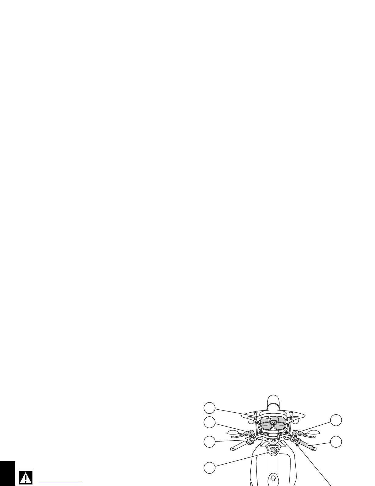
Controls
Warning
This section shows the position and function of the
1
4
3
2
7
6

E
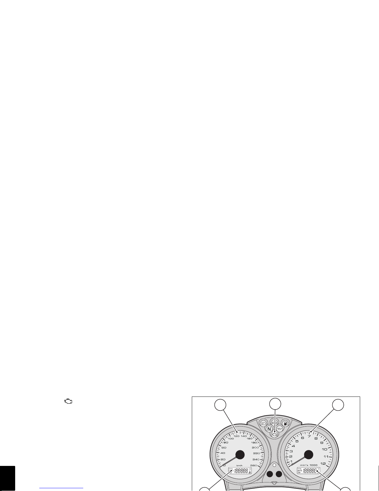
Instrument panel (fig. 4.1 and fig. 4.2)
1) High beam warning light (blue).
Illuminates when the high beam headlight is on.
2) Turn signal warning light (green).
Flashes when a turn signal is on.
3) Low fuel warning light (yellow).
Illuminates when there are approximately 3.5 litres of fuel
left in the tank.
4) Neutral warning light (green).
Illuminates when the gearbox is in neutral.
5) Engine oil pressure warning light (red).
Illuminates when engine oil pressure is too low. This light
1 4 2 5 3
E
7) EOBD light (yellow amber).
Comes on when the engine is locked. Switches off after a
few seconds (normally 1.8 - 2 sec.).
8) Speedometer (km/h).
Indicates road speed.
a) LCD (1):
- Odometer (km).
Shows total distance travelled.
- Trip meter (km).
Indicates the distance travelled since the meter was
last reset or since illumination of the low fuel warning
light (reserve).
- Fuel reserve trip meter.
8
7
9
E
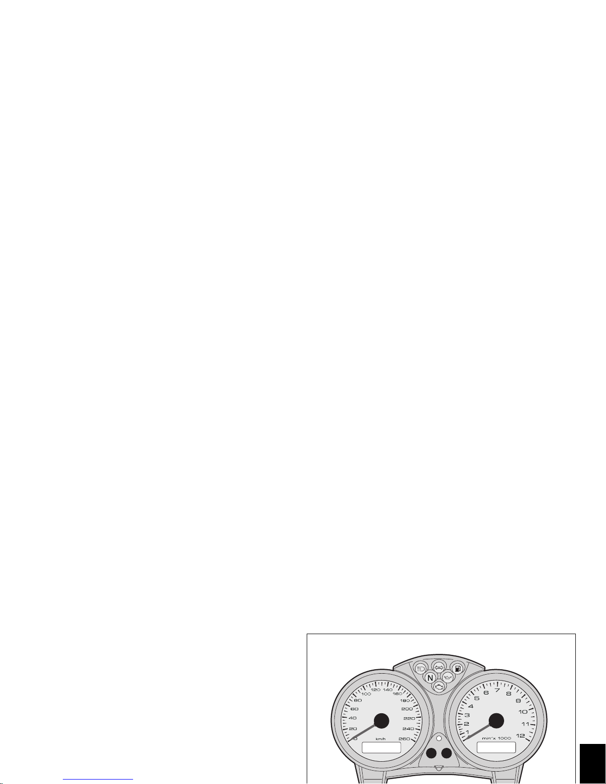
LCD functions
When the engine is switched on (key turned from OFF to
ON), the instrument panel checks all instruments (dials,
display, warning lights), see (fig. 5 and fig. 6).
LCD functions (1)
By pressing button (A, fig. 6) with the key turned to ON, you
can cycle between display of the trip meter and the
odometer and, if the fuel level warning light is on, the fuel
reserve trip meter (latter function).
Resetting the trip meter
If button (A, fig. 6) is held pressed for more than 2 seconds
OFF
E
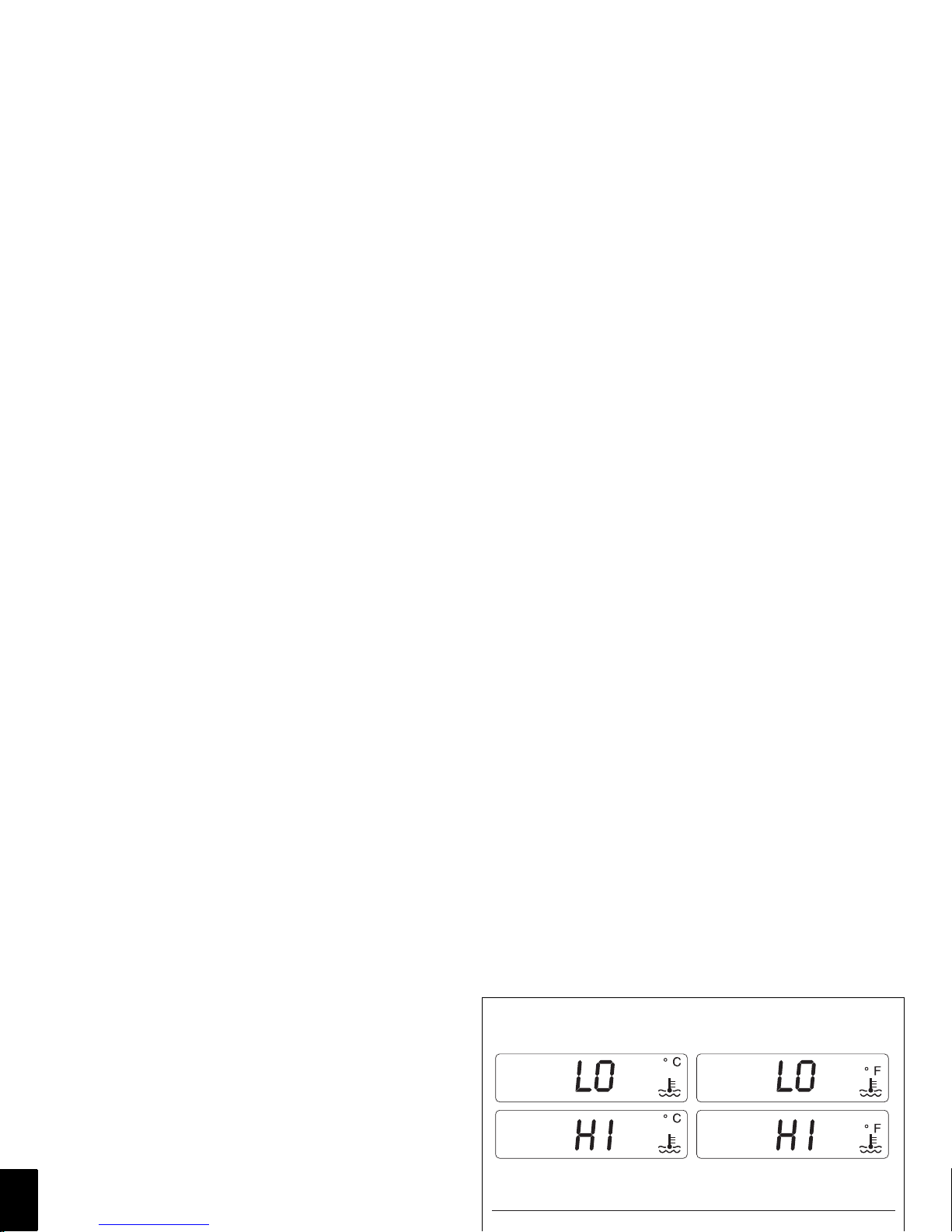
Oil temperature function
If the oil temperature falls below 50 °C / 122 °F, the
message “LO” will appear on the display, and if it rises
above 170 °C/338 °F “HI” will appear.
Fuel level warning light
When the fuel level warning light the word “FUEL”will
appear on display (2, fig. 6) and the fuel reserve trip meter
function will be activated and indicate on display (1, fig. 6)
the number of kilometres travelled in reserve preceded by
the letter “F” (FUEL).
Maintenance indicator function

E
Automatic headlight switch-off function
This function helps reduce battery use by automatically
switching off the headlight.
The device is triggered in two cases:
- in the first case, if you turn the key from OFF to ON
and do not start the engine, After 60 seconds the
headlight will be turned odd and will only turn on
again the next time the key is turned from OFF to ON
or the engine is started.
- in the second case, after normal use of the motorcycle
with the lights on, if the engine is killed using the
ENGINE STOP switch (1, fig. 13). In this case,
60 seconds after the engine is stopped, the

E
The immobilizer system
For additional anti-theft protection, the motorcycle is
equipped with an IMMOBILIZER, an electronic system
that locks the engine automatically whenever the ignition
switch is turned off.
The handgrip of each ignition key contains an electronic
device that modulates the output signal from a special
antenna in the switch when the ignition is switched On.
The modulated signal represents the “password” (which
is changed at each start-up) by which the ECU recognizes
the ignition key. The ECU will only allow the engine to start
if it recognises this password.
Warning
The red key (A) has a rubber sleeve to keep it in perfect
condition, and prevent contact with other keys. Never
remove this protection unless absolutely necessary.
The B keys are the keys for normal use, and are used to:
- start the engine
- open the lock on the fuel tank filler cap
- open the seat lock.
The A key performs all the same functions as the B keys
and it can also be used to reset and re-program other black
keys if necessary.
E
Notes
The three keys are supplied attached to a small tag
(1, fig. 7) bearing their identification number.
Warning
Keep the keys separate, and store the tag (1, fig. 7)
and key A in a safe place.
It is also advisable to use only one of the black keys to
start the motorcycle.
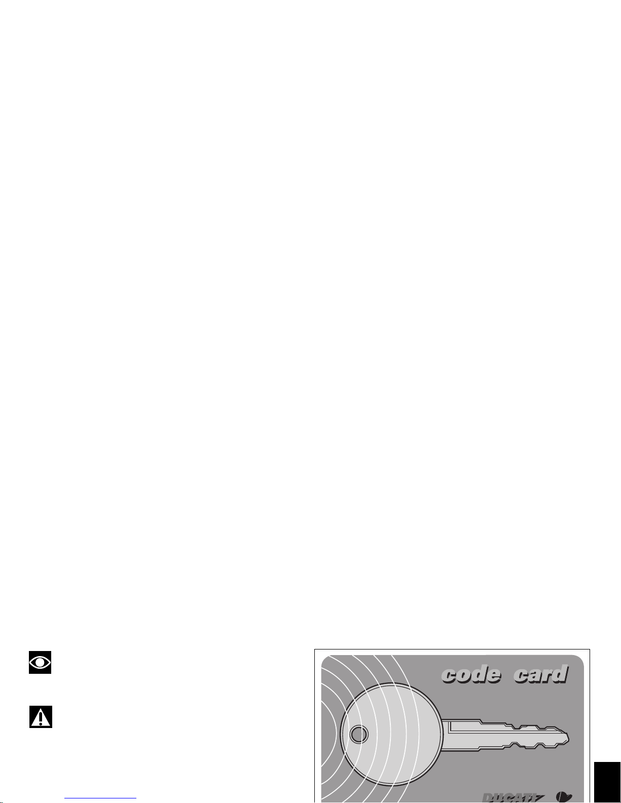
Code card

E
Procedure to override the immobilizer
using the throttle twistgrip
1) Turn the key to ON, turn the twistgrip to fully open
the throttle and hold it open.
The EOBD warning light (7, fig. 4.1) goes off after the
pre-set time of 8 seconds.
2) Release the throttle as soon as the EOBD warning
light turns off.
3) Now enter the electronic release code shown on the
CODE CARD given to the customer when the
motorcycle was handed over by the dealer. The EOBD
warning light will light up and start flashing.
procedure can be repeated as many times as necessary
by turning the key to OFF, then re-starting from step (1).
Notes
If the throttle twistgrip is released before the pre-set
time, the EOBD light comes on again, and it will be
necessary to turn the key to OFF and repeat the
procedure from step (1).

E
Operation
When the ignition key is turned from ON to OFF, the
immobilizer system activates the engine lock. When the
ignition key is turned from OFF to ON to start the engine:
1) if the code is recognised, the warning light (6, fig. 4.1)
on the instrument panel will flash briefly. This means
that the immobilizer system has recognised the code
and disabled the engine lock. When you press the
START (2, fig. 13) button, the engine will start up.
2) If either the warning light (6, fig. 4.1) or the EOBD light
(7, fig. 4.1) remain lit, the code has not been recognized.
In this case, it is advisable to turn the ignition key back
to OFF and then to ON again. If the engine still does not
Duplicate keys
If you need additional keys, contact your DUCATI Service
Centre with all the keys you have in your possession and
your CODE CARD.
DUCATI Service will program new keys and re-program
your original keys, up to a maximum of 8 keys.
DUCATI Service may ask for proof that you are the
legitimate owner of the motorcycle.
The codes for any keys not present during the memory
programming procedure are cancelled, to ensure that any
keys that may have been lost can no longer be used to
start the engine.
E
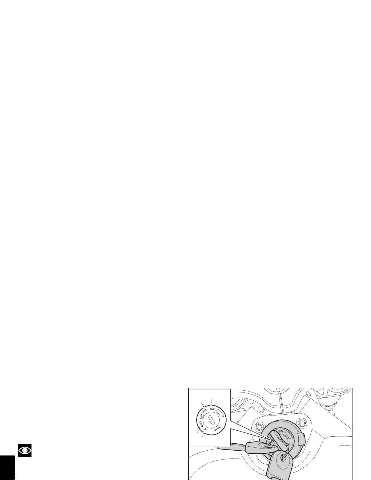
Ignition switch and steering lock (fig. 10)
This is located in front of the fuel tank and has four positions:
A) ON: enables lights and engine operation;
B) OFF: disables lights and engine operation;
C) LOCK: the steering is locked;
D) P: sidelight and steering lock.
Notes
To move the key to the last two positions, push it in
before turning. The key can be removed in positions (B), (C)
and (D).
A
B
C
D

E
Left-hand handlebar switch (fig. 11)
1) Two-position light selector switch:
- position = low beam headlight on;
- position = high beam headlight on.
2) Switch = 3-position turn signal:
- centre position = off;
- position = left turn;
- position = right turn.
To switch off the indicator, press the lever
once it has returned to the centre.
1
4
2

E
Clutch lever (fig. 12)
The lever (1) disengages the clutch. The span adjuster (2)
serves to alter the distance of the lever from the handlebar.
To make the adjustment, keep the lever (1) full forward and
adjust the wheel (2), turning it to one of the four preset
positions, taking account of the fact that:
position n° 1 corresponds to the maximum distance
between the lever and grip, while position n° 4
corresponds to the minimum distance.
When the clutch lever (1) is operated, drive from the
engine to the gearbox and the rear wheel is disengaged.
Correct use of the clutch lever is very important in all
riding situations, especially when moving off.
2
3
4
1
2
E
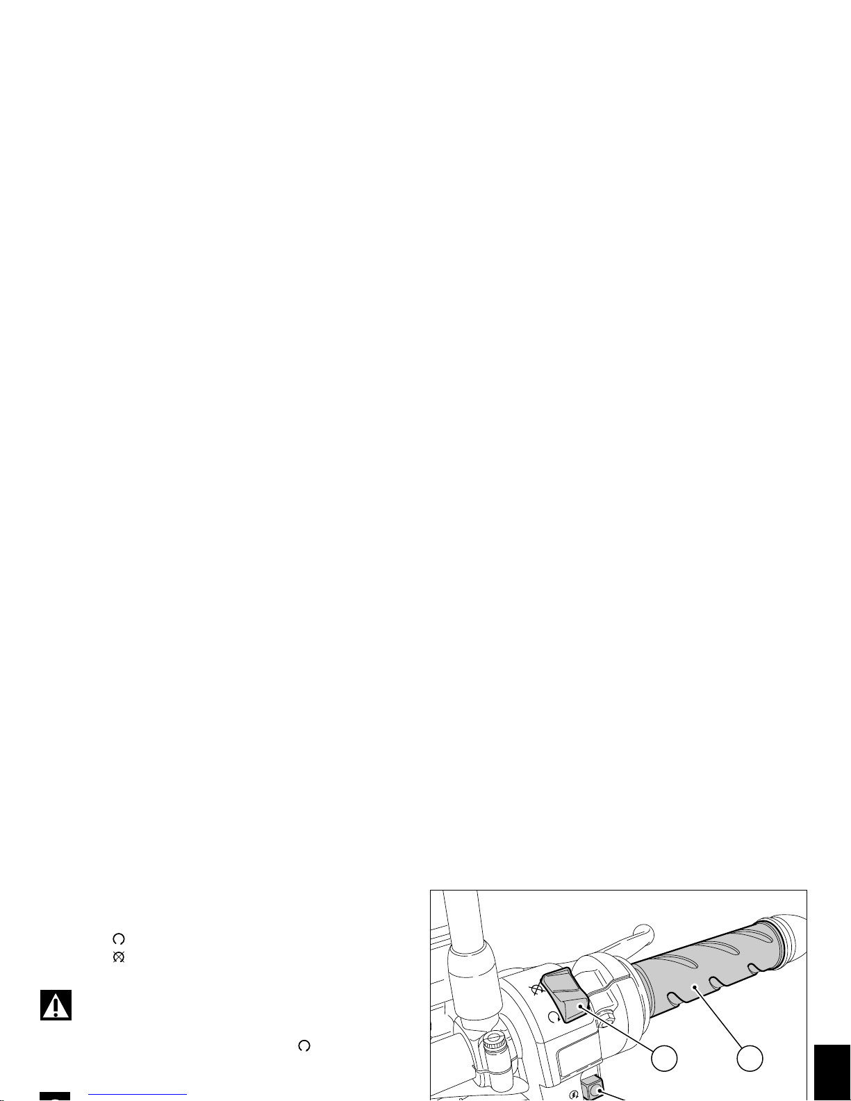
Right-hand handlebar switch (fig. 13)
1) ENGINE STOP switch, with two positions:
- position (RUN) = run;
- position (OFF) = stop engine.
Warning
This switch is mainly intended for use in emergencies
when you need to stop the engine quickly. After the engine
is stopped, return the switch to position to allow the
motorcycle to be started again.
1 3
E
Front brake lever (fig. 14)
Pull the lever (1) towards the twistgrip to operate the front
brake. The system is hydraulically assisted and you only
need to pull the lever gently.
The brake lever has a wheel (2) for adjusting the distance
between lever and twistgrip on the handlebar.
To make the adjustment, hold the lever (1) fully forward and
adjust the wheel (2), turning it to one of the four preset
positions.
Note that:
position n° 1 corresponds to the maximum distance between
the lever and grip, while position n° 4 corresponds to the
minimum distance.
E
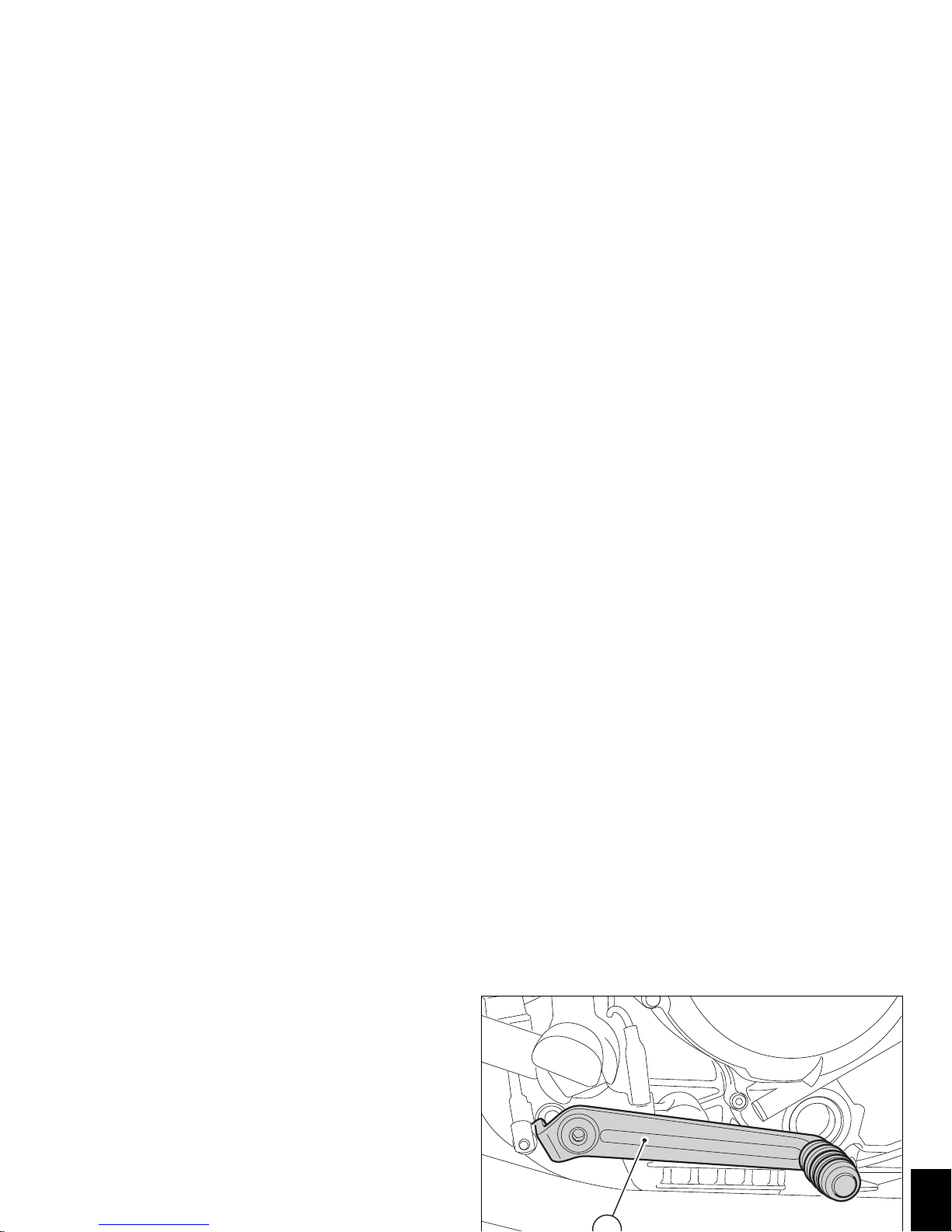
Rear brake pedal (fig. 15)
Push down on the pedal (1) with your foot to operate the
rear brake.
The system is controlled hydraulically.
E
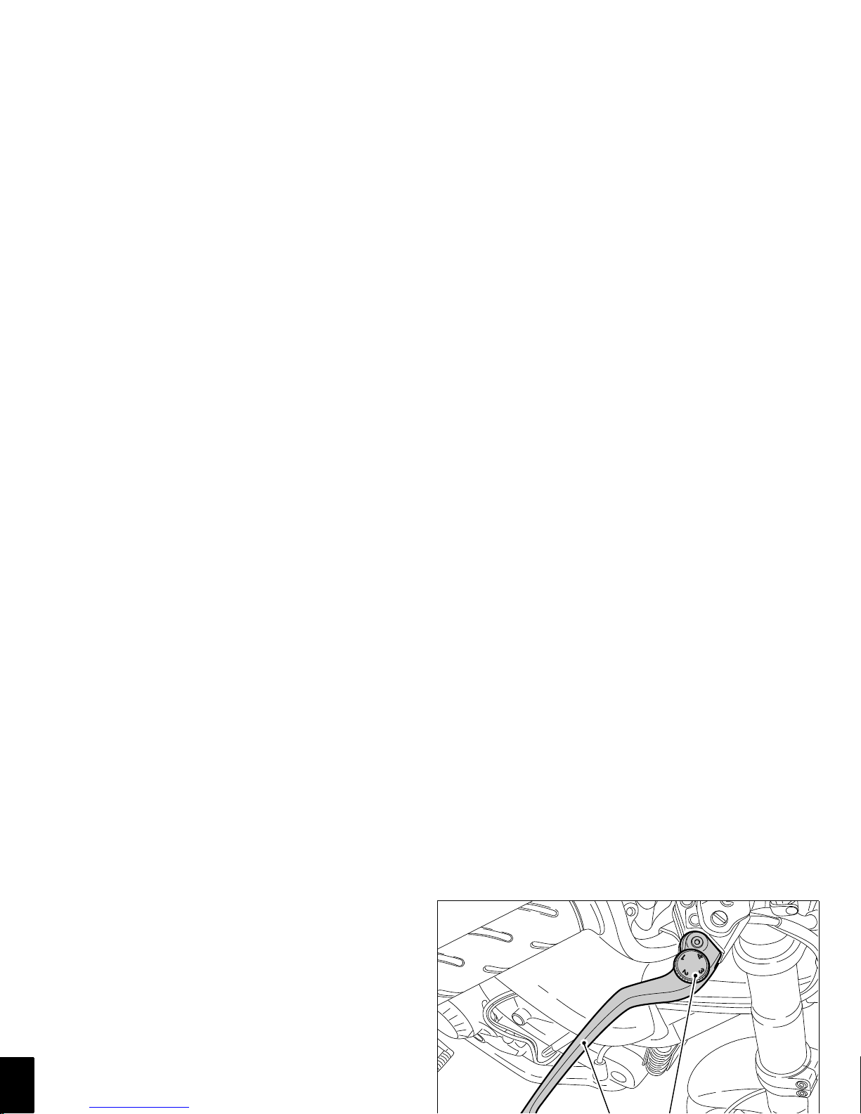
Adjusting the position of the gearchange
and rear brake pedals
The position of the gearchange and rear brake pedals in
relation to the footrests can be adjusted to suit the
requirements of the rider.
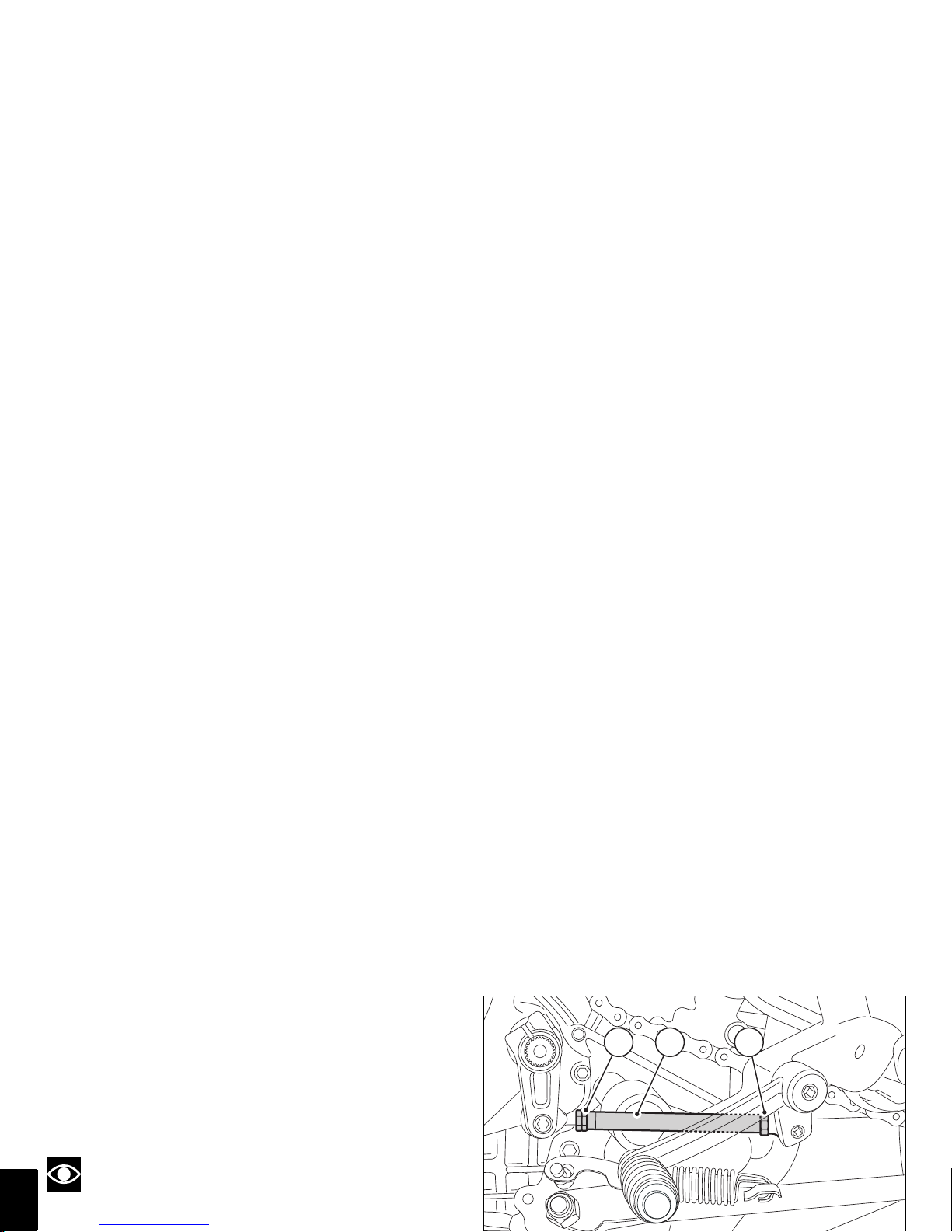
To adjust the position, proceed as follows:
Restrain the tie-rod (1) and slacken the locknuts (2) and (3).
Notes
The locknut (2) has a left-hand thread.
Rotate the tie-rod (1) using an open-ended wrench on the
2 1 3
E
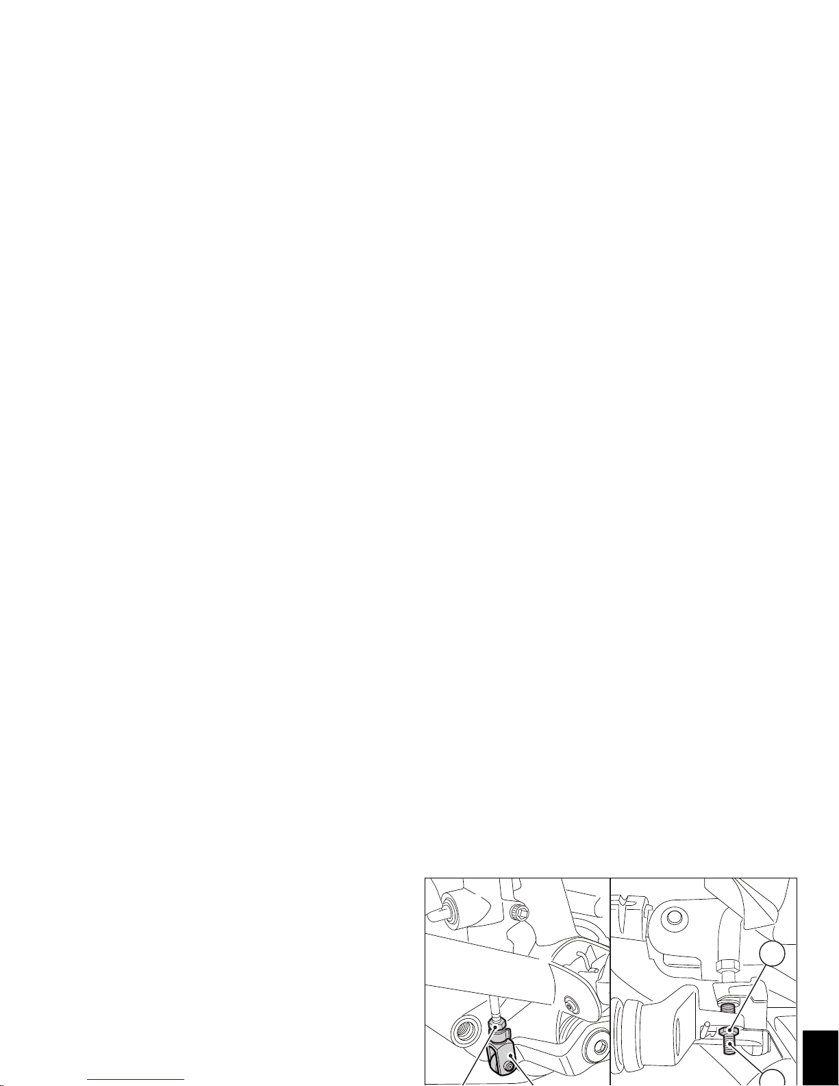
To adjust the position of the rear brake pedal, proceed as
follows:
Loosen the locknut (4).
Turn the pedal travel adjustment bolt (5) until the pedal is in
the desired position.
Tighten the locknut (4).
Operate the pedal by hand to make sure it has 1.5 to 2 mm
of free play before the brake begins to bite.
If not, adjust the length of brake master cylinder pushrod
as follows:
Slacken off the locknut (6) on the pushrod.
Screw the rod into the clevis (7) to increase play, or
unscrew it to reduce play.
4
 Loading...