

Page 1

1
Manuale d'officina
Workshop manual
Monster S4
Monster S4 Fogarty
Model Year 2002
DUCATIMONSTER S4
Page 2

2
Premessa
•
La presente pubblicazione è stata
redatta al fine di fornire ai tecnici
delle Stazioni di Servizio Ducati,
le informazioni fondamentali per
operare in perfetta armonia con i
moderni concetti di "buona
tecnica" e "sicurezza sul lavoro",
per tutti gli interventi di
manutenzione, riparazione e
sostituzione di parti originali, sia
per la parte ciclistica che
motoristica, del motoveicolo in
oggetto.
•
Gli interventi descritti nel
presente manuale, richiedono
esperienza e competenza da
parte dei tecnici preposti, che
sono invitati al pieno rispetto
delle caratteristiche tecniche
originali, riportate dal Costruttore.
•
Alcune informazioni sono state
appositamente omesse, poiché,
a nostro avviso, facenti parte
dell'indispensabile cultura
tecnica di base che un tecnico
specializzato deve possedere.
•
Altre eventuali informazioni
possono essere dedotte dal
catalogo ricambi.
Importante
La presente pubblicazione
contempla inoltre gli indispensabili
controlli da effettuarsi in fase di PRE
CONSEGNA del motoveicolo.
•
La Ducati Motor Holding S.p.A.
declina ogni responsabilità per
errori ed omissioni di carattere
tecnico, prodotti nella redazione
del presente manuale e si riserva
il diritto di apportare qualsiasi
modifica richiesta dall'evoluzione
tecnologica dei suoi motocicli,
senza l'obbligo di divulgazione
tempestiva.
•
Tutte le informazioni riportate,
sono aggiornate alla data di
stampa.
•
Riproduzioni o divulgazioni anche
parziali degli argomenti trattati
nella presente pubblicazione,
sono assolutamente vietate. Ogni
diritto è riservato alla Ducati
Motor Holding S.p.A., alla quale si
dovrà richiedere autorizzazione
(scritta) specificandone la
motivazione.
Ducati Motor Holding S.p.A.
Foreword
• This manual has been prepared
for Ducati Authorized Service
Centers and workshop personnel
involved in the maintenance and
repair of Ducati motorcycles. It
gives fundamental information
on how to work in perfect
harmony with the concepts of
“good technique” and “safety
on work sites” for servicing or
replacing of original spare parts
both for frame and engine parts
concerning this motorcycle.
• All operations described in this
manual must be carried out by
senior skilled technicians, who
are requested to strictly follow
the Manufacturer’s instructions.
• Some information has been
intentionally omitted, as, at our
advice, a specialized technician
must have this technical
background.
• Other information can be taken
from the spare parts catalogue.
Caution
This manual also describes
PRE-DELIVERY checks .
• Ducati Motor Holding S.p.A.
declines all responsibility for any
technical errors or omissions in
this manual and reserves the
right to make changes without
prior notice.
• The information given in this
manual was correct at the time of
going to print.
• Reproduction and disclosure,
even partially, of the contents of
this manual are strictly forbidden
without prior written
authorization of Ducati Motor
Holding S.p.A., which has
exclusive right on this manual.
Applications for authorization
must specify the reasons for
reproduction or disclosure.
Ducati Motor Holding S.p.A.
Page 3

3
Sommario
Contents
Page 4

4
Description 7
Graphic symbols 8
A word of advice 9
General advice on repair work 10
Identification data 11
Description 13
Engine 14
Timing system 14
Fuel injection-ignition system 15
Fuel system 18
Lubrication 19
Cooling system 19
Transmission 20
Brakes 21
Frame 21
Suspensions 22
Wheels 22
Tyres 23
Electric system 24
Performance 24
Weight 24
Colors available for each model 24
Overall dimensions 25
Fuel and lubricants 26
Product specifications 28
Maintenance
29
Routine maintenance 30
Checking the engine oil level 33
Checking the engine oil pressure
34
Changing the engine oil and filter
cartridge 35
Changing the air filter 36
Checking the cylinder
compression 37
Checking the coolant level 38
Changing the coolant 39
Changing the fuel filter 41
Checking brake pad wear. Changing
brake pads 43
Changing the brake fluid 45
Changing the clutch fluid 47
Settings and adjustments 49
Checking valve clearances 50
Adjusting valve clearances 51
Adjusting timing belt tension 53
Throttle body adjustment 55
Adjusting throttle and choke cables
59
Adjusting chain tension 60
Adjusting the position of the gear
change and rear brake pedals 61
Adjusting steering head bearing
play 62
Adjusting the front fork 63
Adjusting the rear shock
absorber 64
Frame 65
Motorcycle component disassembly
sequence 69
Removing the headlight fairing 70
Removing the tank 71
Removing fuel tank
components 72
Removing the battery 73
Removing the battery mount 74
Removing the exhaust system 75
Removing the sprocket cover and
Indicazioni generali 7
Simbologia di redazione 8
Consigli utili 9
Norme generali sugli interventi
riparativi 10
Dati per l’identificazione 11
Generalità 13
Motore 14
Distribuzione 14
Alimentazione - accensione 15
Alimentazione carburante 18
Lubrificazione 19
Raffreddamento 19
Trasmissione 20
Freni 21
Telaio 21
Sospensioni 22
Ruote 22
Pneumatici 23
Impianto elettrico 24
Prestazioni 24
Pesi 24
Colori disponibili per modello 24
Ingombri 25
Rifornimenti 26
Caratteristiche prodotti 27
Manutenzione 29
Manutenzione periodica 30
Controllo livello olio motore 33
Controllo Pressione Olio Motore 34
Sostituzione olio motore e cartuccia
filtro 35
Sostituzione filtro aria 36
Controllo compressione cilindri
motore 37
Controllo livello liquido
refrigerante 38
Sostituzione liquido refrigerante 39
Sostituzione filtro carburante 41
Controllo usura e sostituzione
pastiglie freno 43
Sostituzione liquido impianto
frenante 45
Sostituzione liquido impianto
frizione 47
Registrazioni e regolazioni 49
Controllo gioco valvole 50
Registrazione gioco valvole 51
Registrazione tensione cinghie
distribuzione 53
Registrazione corpo farfallato 55
Regolazione cavi di comando
acceleratore e starter 59
Regolazione tensione catena 60
Registrazione posizione pedale
comando cambio e freno
posteriore 61
Registrazione gioco cuscinetti dello
sterzo 62
Regolazione forcella anteriore 63
Regolazione ammortizzatore
posteriore 64
Mototelaio 65
Schema sequenza di smontaggio
componenti motociclo 68
Smontaggio cupolino 70
Smontaggio serbatoio 71
Smontaggio componenti
Page 5

5
the clutch transmission 76
Removing the gearchange 77
Disconnecting the cooling
system 78
Removing the warning horns 79
Disconnecting the breather pipe
79
Removing the rear brake pedal and
the cylinder support 79
Removing the air box 80
Removing the throttle body 81
Removing the intake manifold 82
Removing the chain sprocket 82
Removing the coolant expansion
tank 83
Removing the oil breather tank 83
Removing the engine 84
Removing the front wheel 86
Refitting the front wheel 87
Removing the rear wheel 88
Changing the rear sprocket 89
Washing the chain 90
Chain lubrication 90
Brake discs 91
Refitting the rear wheel 92
Wheel overhaul 93
Removing the front fork 95
Front fork overhaul 96
Rear suspension 103
Removing and overhauling the
swingarm 104
Removing the rear shock
absorber 107
Changing the monoshock spring
and checking the monoshock 108
Removing the rear suspension
connecting rod and rocker arm 109
Rear suspension rocker arm
overhaul 110
Monoshock linkage overhaul 111
Refitting the rear suspension 112
Brake calipers and master
cylinders 113
Brake hose routing 114
Clutch master cylinder and hose
routing 116
Cooling system 117
Cooling system inspection 118
Checking the frame 120
Changing the steering head
bearings 121
Hoses and bowden cables routing
on the frame 124
Frame torque settings 134
Engine 139
Engine disassembly sequence 143
Engine disassembly 144
General notes on engine overhaul
165
Engine overhaul 166
Engine lubrication circuit 172
Coolant pump 186
Clutch unit 189
Engine reassembly 198
Checking the sensor air gap 219
Checking engine timing 220
Engine torque settings 225
Electronic fuel injectionignition system 229
Description of fuel injection-ignition
serbatoio 72
Smontaggio batteria 73
Smontaggio supporto batteria 74
Smontaggio sistema di scarico 75
Smontaggio coperchio pignone e
rinvio frizione 76
Smontaggio comando cambio 77
Smontaggio impianto di
raffreddamento 78
Smontaggio avvisatori acustici 79
Smontaggio tubo sfiato vapori
basamento 79
Smontaggio supporto pompa pedale freno posteriore 79
Smontaggio scatola filtro aria 80
Smontaggio corpo farfallato 81
Smontaggio collettore aspirazione 82
Smontaggio pignone catena 82
Smontaggio serbatoio d'espansione
acqua 83
Smontaggio serbatoio sfiato
vapori olio 83
Smontaggio motore 84
Smontaggio ruota anteriore 86
Rimontaggio ruota anteriore 87
Smontaggio ruota posteriore 88
Sostituzione della corona 89
Lavaggio della catena 90
Lubrificazione della catena 90
Dischi freno 91
Rimontaggio ruota posteriore 92
Revisione ruota 93
Smontaggio forcella anteriore 95
Revisione forcella 96
Sospensione posteriore 103
Smontaggio e revisione forcellone
oscillante 104
Smontaggio ammortizzatore
posteriore 107
Sostituzione molla e ispezione
ammortizzatore 108
Smontaggio biella e bilanciere
sospensione posteriore 109
Revisione bilanciere sospensione
posteriore 110
Revisione tirante ammortizzatore 111
Rimontaggio sospensione
posteriore 112
Pinze e pompe freno 113
Posizionamento tubazioni freno 114
Pompa e impianto frizione 116
Impianto di raffreddamento
motore 117
Ispezione impianto di
raffreddamento motore 118
Controllo del telaio 120
Sostituzione cuscinetti di sterzo 121
Disposizione dei tubi e delle
trasmissioni flessibili sul telaio 124
Coppie di serraggio mototelaio 130
Motore 139
Schema sequenza di smontaggio
motore 142
Smontaggio componenti motore 144
Note generali sulla revisione dei
componenti del motore 165
Revisione motore 166
Circuito di lubrificazione motore 183
Pompa acqua 186
Gruppo frizione 189
Ricomposizione motore 198
Page 6

6
system 230
Electronic control unit 232
Removing the electronic control
unit 233
Fuel circuit 234
Electric fuel pump 235
Electric injector 236
Pressure regulator 237
Intake air circuit 237
Air pressure/temperature
sensor 238
Coolant temperature
sensor 238
Coil and power module 239
Ignition and injection relays 239
Throttle position sensor 240
Pick-up 240
Operation 241
Ignition - injection system diagram
legend 242
Electrical system 245
Electrical system diagram
legend 248
Instrument panel 249
Battery 251
Immobilizer with transponder 254
Generator 261
Rectifier-regulator 261
Fuses 262
Starter motor 263
Removing the instrument panel
263
Spark plugs 264
Checking the components of the
ignition, indicator and lighting
systems 265
Changing light bulbs 271
Beam setting 273
Arrangement of wiring on the
frame 274
Controllo traferro sensori 219
Verifica fasatura motore 220
Coppie di serraggio motore 222
Impianto iniezione-accensione
elettronica 229
Informazioni generali sul sistema
iniezione - accensione 230
Centralina elettronica 232
Smontaggio centralina
elettronica 233
Circuito carburante 234
Pompa elettrica carburante 235
Elettroiniettore 236
Regolatore di pressione 237
Circuito aria aspirata 237
Sensore temperatura/pressione
aria 238
Sensore temperatura acqua 238
Bobina e modulo di potenza 239
Relè accensione e iniezione 239
Potenziometro posizione farfalla 240
Pick-up 240
Fasi di funzionamento 241
Legenda schema impianto
accensione - iniezione 242
Impianto elettrico 245
Legenda schema impianto
elettrico 247
Cruscotto 249
Batteria 251
Immobilizer a transponder 254
Generatore 261
Regolatore raddrizzatore 261
Fusibili 262
Motorino di avviamento 263
Rimozione cruscotto 263
Candela di accensione 264
Controllo componenti impianti
segnalazione 265
Sostituzione lampadine luci 271
Orientamento del proiettore 273
Disposizione dei cablaggi
sul telaio 274
Page 7

7
Indicazioni generali
Description
Page 8
8
SIMBOLOGIA DI REDAZIONE
•
Per una lettura rapida e razionale
sono stati impiegati simboli che
evidenziano situazioni di
massima attenzione, consigli
pratici o semplici informazioni.
Note
Prestare attenzione al
significato dei simboli, in quanto la
loro funzione è quella di non dovere
ripetere concetti tecnici o
avvertenze di sicurezza. Sono da
considerare, quindi, dei veri e propri
"promemoria". Consultare questa
pagina ogni volta che sorgeranno
dubbi sul loro significato.
❍
Questo simbolo, posto all’inizio
del testo, identifica una operazione
o un intervento che costituisce
parte integrante di una procedura di
smontaggio.
●
Questo simbolo, posto all’inizio
del testo, identifica un dato o un
riferimento particolarmente
importante per l'operazione in
corso.
▲
Questo simbolo, posto all’inizio
del testo, identifica una operazione
di rimontaggio.
Tutte le indicazioni destro o sinistro
si riferiscono al senso di marcia del
motociclo.
Attenzione
La non osservanza delle
istruzioni riportate può creare una
situazione di pericolo e causare
gravi lesioni personali e anche la
morte.
Importante
Indica la possibilità di arrecare
danno al veicolo e/o ai suoi
componenti se le istruzioni riportate
non vengono eseguite.
Note
Fornisce utili informazioni
sull'operazione in corso.
GRAPHIC SYMBOLS
• For easy and rational reading, this
manual uses graphic symbols for
highlighting situations in which
maximum care is required,
practical advice or simple
information.
Note
Please pay maximum
attention to these symbols as they
are meant for not repeating
technical concepts or safety rules.
They must be considered real
“notes”. Read this page in case of
doubts on their meaning.
❍
This symbol at the start of an
item of text indicates an operation
which is part of a disassembly
procedure.
●
This symbol at the start of an
item of text indicates a piece of
information or a reference item
which is particularly important for
the current operation.
▲
This symbol at the start of an
item of text indicates a reassembly
operation.
Left-hand and right-hand
indications refer to the machine as
seen in the direction of travel.
Warning
Failure to follow the
instructions given in text marked
with this symbol can lead to serious
personal injury or death.
Caution
Failure to follow the
instructions in text marked with this
symbol can lead to serious damage
to the motorcycle and/or its
components.
Note
This symbol indicates
additional useful information for the
current operation.
Page 9

9
CONSIGLI UTILI
•
La Ducati consiglia, onde
prevenire inconvenienti e per il
raggiungimento di un ottimo
risultato finale, di attenersi
genericamente alle seguenti
norme:
•
in caso di una probabile
riparazione valutare le
impressioni del Cliente,
evidenzianti anomalie di
funzionamento del motociclo, e
formulare le opportune domande
di chiarimento sui sintomi
dell’inconveniente;
•
diagnosticare in modo chiaro le
cause dell’anomalia. Dal presente
manuale si potranno assimilare le
basi teoriche fondamentali, che
peraltro dovranno essere
integrate dall’esperienza
personale e dalla partecipazione
ai corsi di addestramento
organizzati periodicamente dalla
Ducati:
•
pianificare razionalmente la
riparazione onde evitare tempi
morti come ad esempio il
prelievo di parti di ricambio, la
preparazione degli attrezzi, ecc.;
•
raggiungere il particolare da
riparare limitandosi alle
operazioni essenziali.
•
A tale proposito sarà di valido
aiuto la consultazione della
sequenza di smontaggio esposta
nel presente manuale.
A WORD OF ADVICE
• Ducati would like to offer a word
or two of advice on how to best
ensure an efficient, fault-free
customer service.
• When diagnosing breakdowns,
primary consideration should
always be given to what the
customer reports. Your questions
to the customer should aim to
clarify the problem a step at a
time and lead to an accurate
diagnosis of the source of the
trouble.
• Diagnose the problem
systematically and accurately
before proceeding further. This
manual provides the theoretical
background for troubleshooting.
Further practical experience in
troubleshooting can be obtained
through attendance at Ducati
training courses.
• Repair work should be planned
carefully in advance to prevent
any unnecessary down-time, for
example picking-up of required
spare parts or arrangement of
required tools, etc.
• Limit the number of operations
needed to reach the part to be
repaired to the minimum.
• The disassembly procedures in
this manual describe the most
efficient way to reach a part to be
repaired.
Page 10

10
GENERAL ADVICE ON REPAIR
WORK
• Always use top quality tools.
• Lift the motorcycle only with
devices in full compliance with
relevant European directives.
• During repair work always keep
the tools within reach, possibly in
the right order. Never put them
on the vehicle or in hardly
reachable places or somehow
hidden.
• Work place must be neat and
clean.
• During repair work always
change gaskets, seals and split
pins.
• When loosening or tightening
nuts and bolts, always start with
the largest and always start from
the center. Tighten nuts and
bolts working crossways; tighten
to the specified torque wrench
settings.
• At disassembly, mark any parts
and positions which might easily
be confused at reassembly.
• Use Ducati original spare parts
only. Use the recommended
lubricants only.
• Use special service tools where
specified.
• Ducati Technical Bulletins often
contain up-dated versions of the
service procedures described in
this manual. Check the latest
Bulletins for details.
NORME GENERALI SUGLI
INTERVENTI RIPARATIVI
•
Utilizzare sempre attrezzature di
ottima qualità.
•
Utilizzare, per il sollevamento del
motoveicolo, attrezzatura
espressamente realizzata e
conforme alle direttive Europee.
•
Mantenere, durante le operazioni,
gli attrezzi a portata di mano,
possibilmente secondo una
sequenza predeterminata e
comunque mai sul veicolo o in
posizioni nascoste o poco
accessibili.
•
Mantenere ordinata e pulita la
postazione di lavoro.
•
Sostituire sempre le guarnizioni,
gli anelli di tenuta e le copiglie
con particolari nuovi.
•
Allentando o serrando dadi o viti,
iniziare sempre da quelle con
dimensioni maggiori oppure dal
centro; bloccare alla coppia di
serraggio prescritta seguendo un
percorso incrociato.
•
Contrassegnare sempre
particolari o posizioni che
potrebbero essere scambiati fra
di loro all’atto del rimontaggio.
•
Usare parti di ricambio originali
Ducati ed i lubrificanti delle
marche raccomandate.
•
Usare attrezzi speciali dove
specificato.
•
Consultare le Circolari Tecniche
in quanto potrebbero riportare
dati di regolazione e metodologie
di intervento maggiormente
aggiornate rispetto al presente
manuale.
Page 11
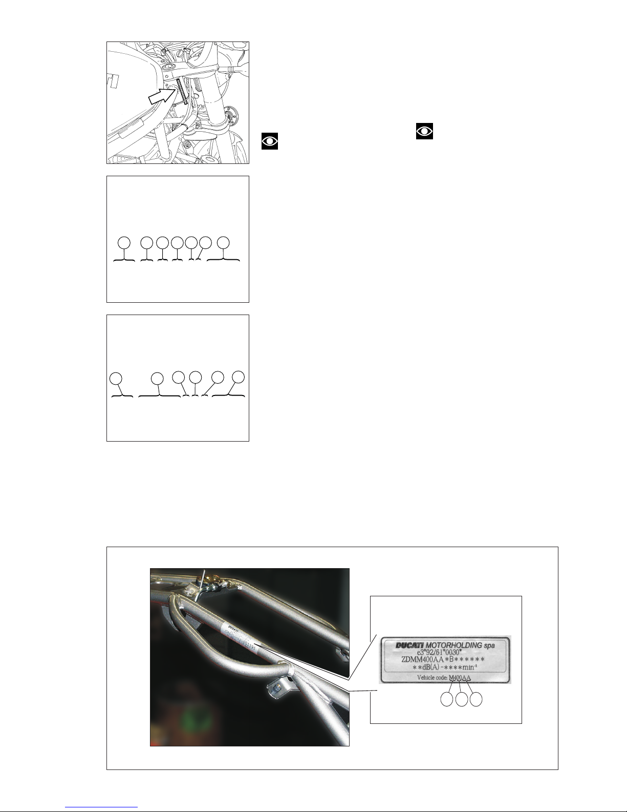
11
Punzonatura del telaio
Versione Europa
Data punched on frame
Europe version
ZDM M4 00 AA XB 000001
2 4
5 6 7
31
DATI PER L’IDENTIFICAZIONE
Ogni motociclo Ducati è
contraddistinto da due numeri di
identificazione, rispettivamente per
il telaio e per il motore, e da una
targhetta costruttore CEE, non
presente nella versione U.S.A.
Note
Questi numeri che identificano
il modello del motociclo e il vehicle
code riportato sulla targhetta
costruttore CEE, sono da citare per la
richiesta di parti di ricambio.
Punzonatura del telaio
Versione Europa
1) Ducati Motor Holding costruttore
2) Tipo - uguale per tutti i modelli
Monster S4
3) Variante
4) Versione
5) Anno
6) Sede costruttore
7) N° progressivo di matricola
Punzonatura del telaio
Versione Stati Uniti
1) Ducati
2) Tipo di motociclo
3) Variante - Numerico oppure X
(Check digit)
4) Model year
5) Sede costruttore
6) N° progressivo di matricola
Vehicle code riportato sulla
targhetta costruttore CEE
1) Tipo di versione uguale per tutti i
modelli Monster S4
2) Variante
- 00 = uguale per tutti i modelli
Monster S4
3) Versione
- AA = Base
Punzonatura del telaio
Versione Stati Uniti
Data punched on frame
USA version
ZDM 1 R B 8 S # X B 000001
43
5
6
1 2
1
2 3
Vehicle code Monster S4 Monster S4 Fogarty
IDENTIFICATION DATA
Each Ducati motorcycle has two
identification numbers, one for the
frame and the other for the engine,
and a manufacturer EEC plate (not
present on the U.S.A. version).
Note
These numbers identify the
motorcycle model and the vehicle
code punched on the manufacturer
EEC plate, please state these
numbers when ordering spare parts.
Data punched on frame
Europe version
1) Manufacturer’s name: Ducati
Motor Holding
2) Type – same for all Monster S4
models
3) Variant
4) Version
5) Year of manufacture
6) Manufacturing plant
7) Progressive serial No.
Data punched on frame
U.S.A. version
1) Ducati
2) Motorcycle type
3) Variant – Number or X (Check digit)
4) Model Year
5) Manufacturing plant
6) Progressive serial No.
Vehicle code punched on
manufacturer’s EEC plate
1) Version type same for all Monster
S4 models
2) Variant
- 00 = same for all Monster S4
models
3) Version
- AA = Basic
Page 12
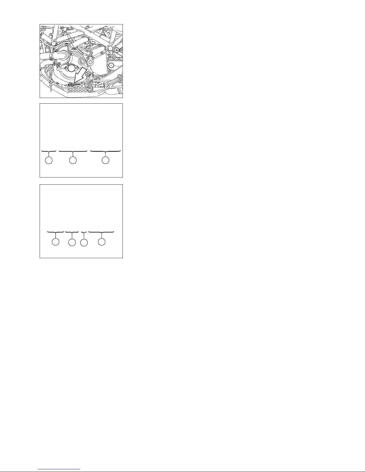
12
ZDM 916 W 4D ∗000001∗
2
1
Punzonatura del motore
Versione Europa
Data punched on engine
Europe version
3
Punzonatura del motore
Versione Europa
1) Ducati Motor Holding, costruttore
2) Tipo di motore
3) N° progressivo di produzione
Punzonatura del motore
Versione Stati Uniti
1) Ducati Motor Holding, costruttore
2) Tipo di motore
3) Model year
4) N° progressivo di produzione
ZDM RB8 X 00 0000
2
3
1 4
Punzonatura del motore
Versione Stati Uniti
Data punched on engine
U.S.A. version
Data punched on engine
Europe version
1) Manufacturer’s name: Ducati
Motor Holding
2) Engine type
3) Progressive production No.
Data punched on engine
U.S.A. version
1) Manufacturer’s name: Ducati
Motor Holding
2) Engine type
3) Model year
4) Progressive production No.
Page 13

Generalità / Description 13
Generalità
Description
Page 14
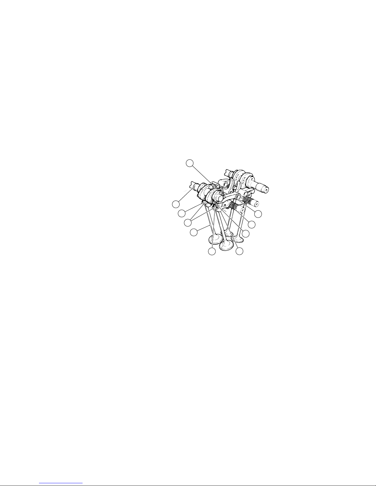
14 Generalità / Description
DISTRIBUZIONE
Desmodromica a quattro valvole
per cilindro comandate da otto
bilancieri (quattro di apertura e
quattro di chiusura) e da due alberi
distribuzione in testa.
È comandata dall’albero motore
mediante ingranaggi cilindrici,
pulegge e cinghie dentate.
Schema distribuzione
desmodromica
1) Bilanciere di apertura (o
superiore);
2) Registro bilanciere superiore;
3) Semianelli;
4) Registro bilanciere di chiusura (o
inferiore);
5) Molla richiamo bilanciere
inferiore;
6) Bilanciere di chiusura (o
inferiore);
7) Albero distribuzione;
8) Valvola.
Valvole
Diametro valvole aspirazione:
33 mm
Diametro valvole di scarico:
29 mm
MOTORE
Bicilindrico a 4 tempi a “L”
longitudinale di 90 ° - ciclo otto 4
tempi
Alesaggio:
94 mm
Corsa:
68 mm
Cilindrata totale:
916 cm
3
Rapporto di compressione:
11±0.5 : 1
Potenza max. all’albero (95/1/CE):
74 kW (101 CV)
al regime di:
8.750 min
-1
Coppia max. all'albero (95/1/CE)
92 Nm a 7.000 min
-1
Regime max.:
9.000 min
-1
ENGINE
4-stroke otto cycle 90 ° “L” twincylinder.
Bore:
94 mm
Stroke:
68 mm
Capacity:
916 cu. cm
Compression ratio:
11±0.5:1
Max. power at crankshaft (95/1/EC):
74 kW (101 HP)
at:
8,750 rpm
Max. crankshaft torque (95/1/EC)
92 Nm at 7,000 rpm
Max. engine speed:
9,000 rpm
TIMING SYSTEM
Desmodromic valve timing system.
Four valves per cylinder controlled
by eight rocker arms (four closing
and four opening). Two overhead
camshafts.
Timing system, crankshaft-driven
over spur gears, belt rollers and
toothed belts.
Desmodromic valve timing
1) Opening (or upper) rocker arm
2) Opening (or upper) rocker arm
shim
3) Split rings
4) Closing (or lower) rocker arm
shim
5) Lower rocker arm return spring
6) Closing (or lower) rocker arm
7) Camshaft
8) Valve
Valves
Intake valve diameter:
33 mm
Exhaust valve diameter:
29 mm
1
2
4
6
8
6
7
1
3
5
Page 15

Generalità / Description 15
Diagramma distribuzione
Dati di rilevamento con gioco 1 mm.
Apertura valvola aspirazione:
11 ° P.P.M.S.
Chiusura valvola aspirazione:
61 ° D.P.M.I.
Apertura valvola scarico:
62 ° P.P.M.I.
Chiusura valvola scarico:
18 ° D.P.M.S.
Alzata valvole
Dati di rilevamento con gioco 0 mm.
Aspirazione:
9,6 mm
Scarico:
8,74 mm
Gioco di funzionamento delle
punterie
Rilevamento dati con motore
freddo.
Valori per il montaggio:
Bilanciere di apertura
Aspirazione:
0,13 ÷ 0,18 mm
Scarico:
0,18 ÷ 0,23 mm
Bilanciere di chiusura
Aspirazione:
0,13 ÷ 0,18 mm
Scarico:
0,08 ÷ 0,13 mm
Valori per il controllo:
Bilanciere di apertura
Aspirazione:
0,05 ÷ 0,18 mm
Scarico:
0,05 ÷ 0,23 mm
Bilanciere di chiusura
Aspirazione:
0,13 ÷ 0,25 mm
Scarico:
0,08 ÷ 0,20 mm
ALIMENTAZIONE ACCENSIONE
Alimentazione ad iniezione
elettronica indiretta con 1 iniettore
per cilindro.
Accensione elettronica a scarica
induttiva
Marca:
MARELLI
Tipo:
I.A.W. 5.9 M
Trattasi di un sistema integrato per il
controllo dell'accensione e
dell'iniezione di tipo sequenziale
fasato.
Detto controllo è realizzato
mediante iniettori che prevedono
due stati di funzionamento stabili:
Aperto: l'iniettore eroga il
carburante;
Chiuso: l'iniettore non eroga il
carburante.
Timing
Data measured with 1 mm
clearance.
Intake valve opens at:
11° before TDC.
Intake valve closes at:
61° after BDC.
Exhaust valve opens at:
62° before BDC.
Exhaust valve closes at:
18° after TDC.
Valve lift
Data measured with 0 mm
clearance.
Intake:
9.6 mm
Exhaust:
8.74 mm
Tappet clearances
(with engine cold)
Mounting values:
Opening rocker arm
Intake:
0.13-0.18 mm
Exhaust:
0.18-0.23 mm
Closing rocker arm
Intake:
0.13-0.18 mm
Exhaust:
0.08-0.13 mm
Control values:
Opening rocker arm
Intake:
0.05-0.18 mm
Exhaust:
0.05-0.23 mm
Closing rocker arm
Intake:
0.13-0.25 mm
Exhaust:
0.08-0.20 mm
FUEL INJECTION - IGNITION
SYSTEM
Electronic indirect fuel injection
with 1 injector per cylinder.
Electronic inductive discharge
ignition unit.
Make:
MARELLI
Type:
I.A.W. 5.9 M
Integrated sequential timed system
to control injection and ignition.
Two injectors control this system
through two steady operational
phases:
Open: the injector feeds fuel;
Closed: the injector does not feed
fuel.
Page 16

16 Generalità / Description
La centralina è in grado di
modulare la quantità di carburante
erogato variando i tempi di apertura
degli iniettori.
Il controllo dell’accensione è
realizzato agendo su un sistema di
accensione a scarica induttiva
composto da due bobine integrate
(una per cilindro).
Il sistema di controllo “vede” il
motore attraverso un certo numero
di ingressi collegati ai
corrispondenti sensori, ogni
sensore svolge una specifica
funzione per fornire alla centralina
I.A.W. un quadro completo sul
funzionamento del motore
stesso:
Il sensore motore fase/giri fornisce
un segnale che consente la
determinazione della velocità di
rotazione del motore e la corretta
fasatura rispetto al P.M.S.;
Il potenziometro farfalla fornisce
un segnale funzione dell’angolo di
apertura delle valvole a farfalla;
Il sensore di pressione assoluta
fornisce un segnale funzione della
pressione barometrica ambientale;
Il sensore di temperatura acqua
fornisce un segnale funzione della
temperatura di esercizio del motore;
Il sensore di temperatura aria
fornisce un segnale funzione della
temperatura dell’aria aspirata dal
motore.
Per l’ottimizzazione di questo
sistema è stata adottata una
strategia di controllo chiamata
“Alfa/N”. Gli ingressi principali a cui
il sistema fa riferimento per
controllare l’iniezione e l’accensione
sono l’angolo di apertura della
farfalla (Alfa) ed il regime di
rotazione del motore (N). Nella
memoria della centralina sono
presenti delle tabelle che ad un
certo regime di rotazione ed ad un
certo angolo di apertura farfalla,
fanno corrispondere una durata
dell’impulso di iniezione, un angolo
di fase dell’iniezione e un angolo di
anticipo dell’accensione. Gli altri
ingressi del sistema (temperatura
acqua, temperatura aria, pressione,
tensione batteria) intervengono nel
controllo modificando coefficienti di
correzione applicati ai valori forniti
dalle tabelle “Alfa/N”. Il sistema
introduce poi ulteriori correzioni
nelle condizioni di funzionamento
che richiedono particolari modalità
di accensione e di alimentazione
(fase di avviamento, repentine
aperture o improvvise chiusure del
comando gas).
Candele
Marca:
CHAMPION
Tipo:
RA 59 GC
The control unit meters out the
amount of fuel for the injectors and
controls the injector opening times.
Ignition is controlled by an inductive
discharge system consisting of two
integrated coils (one per cylinder).
The control system reads the
engine status from a series of
inputs connected to sensors. Each
sensor supplies the I.A.W. control
unit with a specific item of
information necessary to build up a
complete picture of the current
engine operating status.
The engine (timing/rpm) sensor
signal is a function of rpm and
timing with respect to TDC.
The throttle position sensor signal
indicates the throttle opening angle.
The absolute pressure sensor
provides a signal indicating the
ambient barometric pressure.
The coolant temperature sensor
signal indicates the current engine
operating temperature.
The air temperature sensor signal
indicates the temperature of the air
taken in by the engine.
The control system uses the “Alfa/
N” control strategy to optimize
engine operation; it uses the inputs
for the throttle angle (Alfa) and
engine speed (N) to control fuel
injection and ignition.
The control unit memory contains
software tables which, at a certain
engine rpm value and throttle
position, give an injection pulse
duration, an injection timing angle
and an ignition advance angle.
The other system inputs (coolant
temperature, air temperature,
pressure and battery voltage)
modify the correction factors
applied to the values in the “Alfa/N”
tables. The system applies other
correction factors under those
conditions (such as starting, sudden
opening and closing of the throttle)
where special ignition or injection
methods are required.
Spark plugs
Make:
CHAMPION
Type:
RA 59 GC
Page 17
Generalità / Description 17
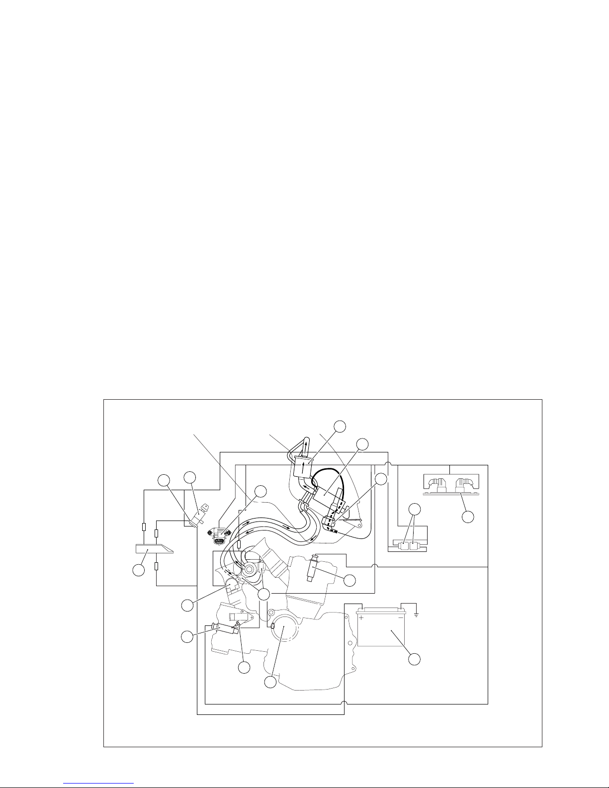
Il sistema di iniezione è
composto dai seguenti
elementi:
1) Centralina elettronica
2) Relè
3) Batteria
4) Bobina (una per cilindro)
5) Elettroiniettore (uno per
cilindro)
6) Centralina Immobilizer
7) Sensore temperatura / pressione
aria
8) Ricevitore Immobilizer
9) Commutatore a chiave
10) Potenziometro a farfalla
11) Sonda livello carburante
12) Pompa carburante
13) Filtro carburante
14) Ingranaggio condotto
distrbuzione
15) Sensore temperatura acqua
The injection system consists
of the following:
1) Electronic control unit
2) Relays
3) Battery
4) Coil (one each cylinder)
5) Electric injector (one each
cylinder)
6) Immobilizer control unit
7) Air temperature/pressure sensor
8) Immobilizer receiving device
9) Key-operated switch
10) Throttle position sensor
11) Fuel level sensor
12) Fuel pump
13) Fuel filter
14) Timing driven gear
15) Coolant temperature sensor
7
9
8
6
10
4
15
14
3
5
4
1
2
11
12
13
Page 18
18 Generalità / Description
ALIMENTAZIONE
CARBURANTE
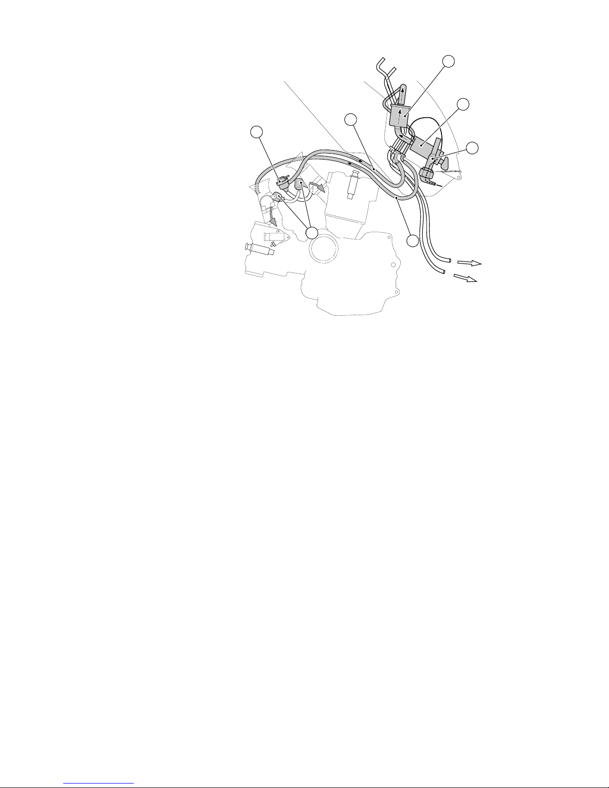
I componenti l’impianto di
alimentazione carburante sono
installati su di una flangia fissata
sotto al serbatoio.
L’impianto è composto da:
1) Pompa elettrica
2) Filtro carburante
3) Indicatore livello carburante
4) Regolatore di pressione
5) Iniettori
a) Mandata
b) Ritorno
FUEL SYSTEM
Fuel system components are fitted
onto a flange under the fuel tank.
The fuel system consists of the
following:
1) Electric pump
2) Fuel filter
3) Fuel level indicator
4) Pressure regulator
5) Injectors
a) Delivery line
b) Return line
5
4
b
a
3
1
2
Page 19
Generalità / Description 19
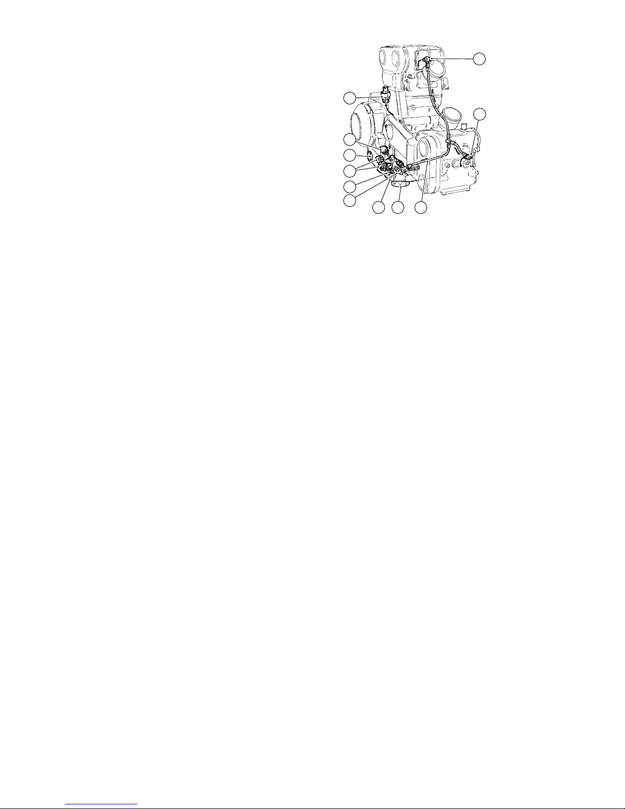
LUBRIFICAZIONE
Forzata a mezzo pompa ad
ingranaggi, con valvola by-pass di
sovrapressione, incorporata, rete di
filtraggio in aspirazione cartuccia
intercambiabile in mandata con
valvola di sicurezza per intasamento
della stessa, indicatore bassa
pressione sul cruscotto.
L’impianto è composto da:
1) Raccordo tubo sfiato vapori coppa
olio
2) Tappo immissione olio
3) Indicatore di livello
4) Ingranaggi pompa olio
5) Filtro a rete in aspirazione
6) Pressostato
7) Coppa olio
8) Cartuccia filtro in mandata
9) Tubazione mandata olio alle teste
10) Raccordo testa orizzontale
11) Raccordo testa verticale
RAFFREDDAMENTO
A liquido a circuito pressurizzato con
radiatore e termostato a
miscelazione. Una pompa
centrifuga, comandata dall’albero di
distribuzione, mette in circolazione il
liquido e un serbatoio di espansione
recupera le dilatazioni termiche del
refrigerante.
Capacità circuito:
3,5 litri
Valore di pressione massima
raggiungibile prima dell'apertura del
tappo:
1,2 bar.
Portata pompa:
35 lt/min a 6.000 min
-1
Termostato
Inizio apertura:
65 °C±2 °C
Inserzione elettroventola:
103 °C
Diserzione elettroventola:
102 °C
LUBRICATION
Forced lubrication by gear pump.
Built-in pressure relief by-pass valve.
Mesh intake filter. Disposable filter
cartridge on intake with clogged
cartridge safety valve. Low oil
pressure indicator on instrument
panel.
The lubrication system consists of
the following:
1) Oil sump fume/breather pipe
2) Oil filler cap
3) Oil level indicator
4) Oil pump gears
5) Mesh intake filter
6) Pressure switch
7) Oil sump
8) Oil delivery filter cartridge
9) Oil delivery tube to heads
10) Horizontal head union
11) Vertical head union
11
1
2
3
5
6
7 8 9
10
4
COOLING SYSTEM
Fluid cooling through pressurized
circuit with cooler and mixing
thermostat. Coolant is pumped by a
centrifugal pump driven by the
camshaft. The circuit has an
expansion tank to take up coolant
when it expands from heat.
Circuit capacity:
3.5 l
Max. pressure value before filler cap
is opened:
1.2 bar
Pump flow rate:
35 l/min at 6,000 rpm
Thermostat
Opening start:
65 °C±2 °C
Electric fan connection:
103 °C
Electric fan disconnection:
102 °C
Page 20

20 Generalità / Description
TRASMISSIONE
Primaria
Ad ingranaggi diritti.
Rapporto di trasmissione: 59/32
Frizione a secco a dischi multipli:
8 condotti (7 piani + 1 bombato) +
7 conduttori con 14 superfici di
attrito; 6 molle elicoidali di
pressione. Comandata da un circuito
idraulico azionato da una leva sul
semimanubrio sinistro.
Trasmissione fra motore e albero
primario del cambio ad ingranaggi a
denti diritti. Meccanismo di
selezione delle marce con tamburo
e forcelle. Una leva articolata
comanda la rotazione del tamburo.
Cambio a 6 rapporti.
Secondaria
Pignone uscita cambio n° 15 denti.
Corona posteriore n° 37 denti.
Rapporti totali
1ª 37/15 11,21
2ª 30/17 8,01
3ª 27/20 6,13
4ª 24/22 5,37
5ª 23/24 4,735
6ª 24/28 4,34
Trasmissione finale mediante
catena:
DID
Tipo:
525 HV
Dimensioni (passo x larghezza
interna tra le piastrine)
5/8" (15,875 mm) x5/16" (7,93
mm)
Diametro dei perni:
10,16 mm
n° maglie:
100
TRANSMISSION
Primary drive
through spur gears.
Drive ratio: 59/32
Dry multi-plate clutch: 8 driven
plates (7 flat + 1 convex) + 7 drive
plates with 14 friction surfaces. 6
pressure coil springs.
Clutch is hydraulically controlled by
a lever on the LH handlebar. Primary
drive between gearbox mainshaft
and engine by spur gears. Selector
drum and fork gear selector system.
A lever linkage controls selector
drum rotation.
6-speed gearbox.
Secondary drive
15-tooth gearbox output sprocket
37-tooth rear sprocket
Gearbox ratios
1
st
37/15 11.21
2
nd
30/17 8.01
3
rd
27/20 6.13
4
th
24/22 5.37
5
th
23/24 4.735
6
th
24/28 4.34
Final drive -from gearbox to rear
wheel- by chain:
DID
Type:
525 HV
Dimensions (pitch x inside width
between side plates)
5/8" (15.875 mm) x5/16" (7.93
mm)
Pin diameter:
10.16 mm
No. of links:
100
Page 21

Generalità / Description 21
FRENI
Anteriore
A doppio disco forato in acciaio.
Diametro disco:
320 mm
Comando idraulico mediante leva
sul semimanubrio destro.
Superficie frenante:
88 cm
2
Pinze freno a pistoni differenziati.
Marca:
BREMBO
Tipo:
P4.30/34-4 pistoni
Tipo pompa:
PS 16
Materiale attrito:
TOSHIBA TT2802
Posteriore
A disco fisso forato, in acciaio.
Diametro disco:
245 mm
Comando idraulico mediante pedale
sul lato destro.
Superficie frenante:
25 cm
2
Pinza freno:
Ø cilindro 32 mm
Marca:
BREMBO P2-I05N
Tipo:
34 Ø
Tipo pompa:
PS 11
Materiale attrito:
FERIT I/D 450 FF
TELAIO
Il telaio è di tipo tubolare in acciaio
ad alta resistenza.
Inclinazione cannotto (a moto
scarica):
24°
Angolo di sterzata (per parte):
30°
Avancorsa:
102 mm
BRAKES
Front brake
Drilled steel twin disc
Disc diameter:
320 mm
Front brake hydraulically controlled
by a lever on RH handlebar.
Braking area:
88 sq. cm
Brake caliper with differential
pistons.
Make:
BREMBO
Type:
P4.30/34-4 pistons
Master cylinder:
PS 16
Pad friction material:
TOSHIBA TT2802
Rear brake
Fixed drilled steel disc
Disc diameter:
245 mm
Hydraulically controlled by a brake
pedal on RH side.
Braking area:
25 sq. cm
Brake caliper:
cylinder diameter: 32 mm
Make:
BREMBO P2-I05N
Type:
34 Ø
Master cylinder:
PS 11
Pad friction material:
FERIT I/D 450 FF
FRAME
High-strength steel tube trellis
frame.
Steering head angle (unladen):
24°
Steering angle (each side):
30°
Rake:
102 mm
Page 22

22 Generalità / Description
SOSPENSIONI
Anteriore
A forcella oleodinamica a steli
rovesciati dotata di sistema di
regolazione esterna del freno
idraulico in estensione e
compressione e del precarico delle
molle interne agli steli.
Diametro tubi portanti:
43 mm
Corsa sull’asse steli:
130 mm
Posteriore
Ad azionamento progressivo
ottenuto con l’interposizione di un
bilanciere tra telaio e fulcro
superiore dell’ammortizzatore.
L’ammortizzatore, regolabile in
estensione, in compressione e nel
precarico della molla, è infulcrato
nella parte inferiore ad un forcellone
oscillante in lega leggera. Il
forcellone ruota intorno al perno
fulcro passante per il motore.
Questo sistema conferisce al mezzo
eccezionali doti di stabilità.
Corsa:
65 mm
Escursione ruota posteriore:
144 mm
RUOTE
Cerchi in lega leggera a cinque
razze.
Anteriore
Marca
MARCHESINI
Dimensioni
3,50 x 17"
Posteriore
Marca
MARCHESINI
Dimensioni :
5,50 x 17"
Le ruote sono a perno estraibile.
Diametro perni ruota:
25 mm
La ruota posteriore è provvista di
uno speciale parastrappi.
SUSPENSIONS
Front suspension
Hydraulic upside-down fork
equipped with outer adjusters for
rebound and compression damping
and fork legs inner springs pre-load
adjustment.
Stanchion diameter:
43 mm
Travel along leg axis:
130 mm
Rear suspension
Progressive suspension with rocker
connecting frame and top pivot
point of rear shock absorber. Shock
absorber features a compression,
rebound and spring preload
adjustment and is hinged on lightalloy swinging arm at the bottom
end. The swinging arm rotates on a
pivot pin passing through the
engine. This system ensures
excellent stability.
Stroke:
65 mm
Rear wheel travel:
144 mm
WHEELS
Light-alloy 5-spoke wheel rims.
Front
Make:
MARCHESINI
Size
3.50 x 17"
Rear
Make:
MARCHESINI
Size:
5.50 x 17"
Wheel shafts can be removed.
Wheel shaft diameter:
25 mm
Rear wheel is fitted with a special
rubber cush drive damper.
Page 23
Generalità / Description 23
PNEUMATICI
Anteriore
Struttura:
radiale tipo “tubeless”
Dimensione:
120/70-ZR17
Posteriore
Struttura:
radiale tipo “tubeless”
Dimensione:
180/55
Pressione Bar Kg/cm²
pneumatici
(a freddo)
Con pilota +
bagaglio
Anteriore: 2,1 2,3
Posteriore: 2,2 2,4
Con pilota +
passeggero +
bagaglio
Anteriore: 2,4 2,6
Posteriore: 2,5 2,7
Importante
In caso di sostituzione del
pneumatico si consiglia di utilizzare
marca e tipo di primo
equipaggiamento. Misurare la
pressione dei pneumatici quando
essi sono freddi.
Al fine di salvaguardare la rotondità
del cerchio anteriore percorrendo
strade molto sconnesse aumentare
la pressione di gonfiaggio del
pneumatico di 0,2÷0,3 bar.
TYRES
Front
Type:
radial, tubeless
Size:
120/70-ZR17
Rear
Type:
radial, tubeless
Size:
180/55
Tyre Bar Kg/sq. cm
pressure
(cold)
With rider +
luggage
Front: 2.1 2.3
Rear: 2.2 2.4
With rider +
pillion rider +
luggage
Front: 2.4 2.6
Rear: 2.5 2.7
Caution
When changing tyres always
fit the original make and type tyres.
Measure tyre pressure when the
tyres are cold.
To prevent front wheel rim damage
when riding on rough roads,
increase front tyre pressure by 0.2-
0.3 bar.
Page 24

24 Generalità / Description
IMPIANTO ELETTRICO
Formato dai seguenti particolari
principali:
Proiettore anteriore
composto da:
unità anabbagliante poliellissoidale
a condensatore 12V-55W;
unità abbagliante 12V-55W;
luce di posizione con lampada
12V-5W.
Comandi elettrici sui semimanubri.
Indicatori direzione, lampade 12V10W.
Avvisatore acustico.
Interruttori luci arresto.
Batteria, 12V-10 Ah.
Alternatore Denso 12V-520W.
Regolatore elettronico, protetto
con fusibile da 40 A.
Motorino avviamento, 12V-0,7 kW.
Fanale posteriore, lampada doppio
filamento 12V-5/21W per
segnalazione arresto e luce
posizione; lampada 12V-5W per
illuminazione targa.
PRESTAZIONI
Velocità max. (solo conduttore):
225 Km/h
PESI
In ordine di marcia (senza
carburante):
190 Kg
anteriore:
104 Kg
posteriore:
108 Kg
A pieno carico:
390 Kg
COLORI DISPONIBILI PER
MODELLO
•
Rosso Anniversary Ducati
Cod. 473.101 (PPG)
•
Grigio opaco Ducati
Cod. 653.6047 (SALCHI)
•
Nero metallizzato Ducati
Cod. 291.500 (PPG)
•
Giallo Ducati
Cod. 473.201 (PPG)
Versione Fogarty
•
Rosso Anniversary Ducati
Cod. 473.101 (PPG)
ELECTRICAL SYSTEM
Main components:
Front headlamp
consisting of:
12V-55W poly-ellipsoidal low beam
lamp, with capacitor;
12V-55W high beam lamp;
parking light with 12V-5W bulb.
Electric controls on handlebars.
Turn indicator 12V-10W bulbs.
Horn.
Stop light switches.
Battery 12V-10 Ah.
Denso generator 12V-520W.
Electronic rectifier, protected by a
40 A fuse.
Starter motor, 12V-0.7 kW.
Tail light, 12V-5/21W double-
filament bulb for stop and parking
lights; 12V-5W bulb for number
plate light.
PERFORMANCE
Max. speed (rider only):
225 Kph
WEIGHT
In running order (without fuel):
190 Kg
Front:
104 Kg
Rear:
108 Kg
Full load:
390 Kg
COLORS AVAILABLE FOR
EACH MODEL
• Ducati Anniversary Red
473.101 (PPG);
• Ducati Mat Grey 653.6047
(SALCHI);
• Ducati Metallic Black
291.500 (PPG);
• Ducati Yellow
473.201 (PPG).
Fogarty Version
•
Ducati Anniversary Red
473.101 (PPG)
Page 25
Generalità / Description 25
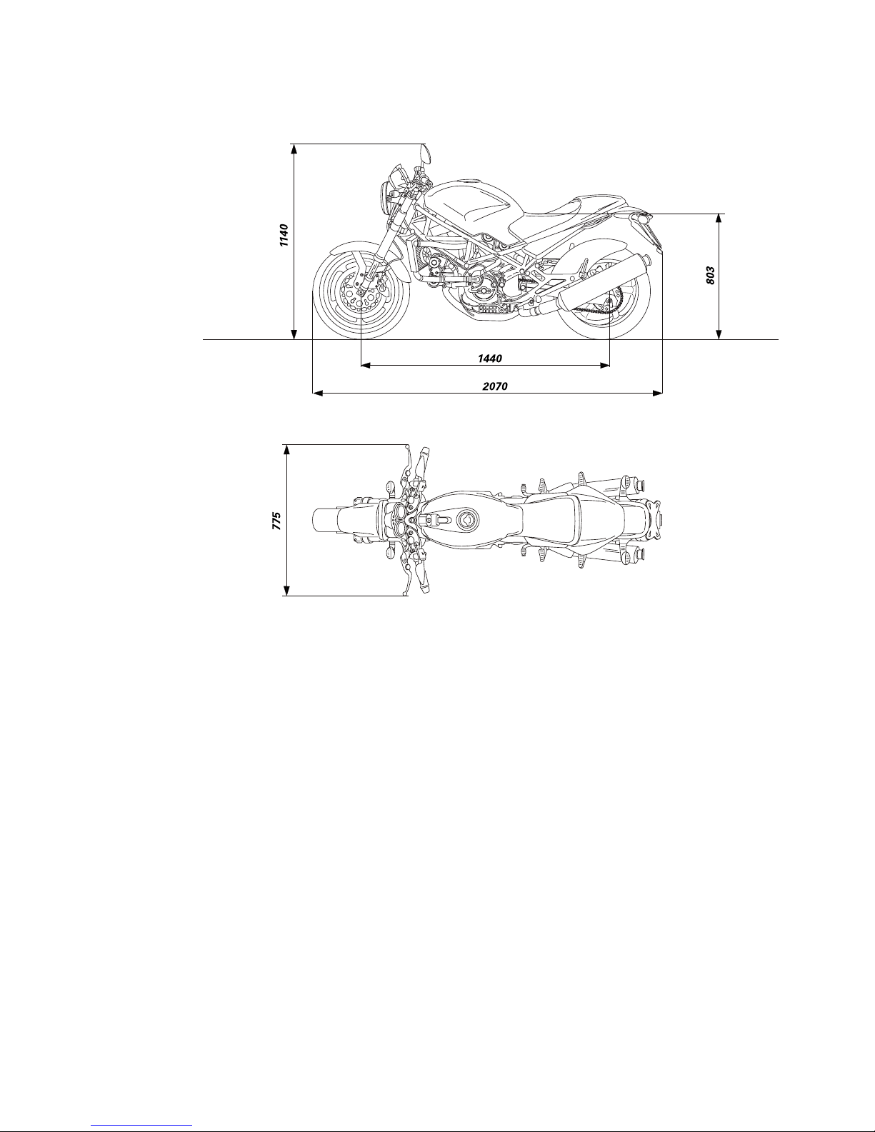
INGOMBRI (mm)
OVERALL DIMENSIONS (mm)
Page 26
26 Generalità / Description
RIFORNIMENTI Tipo dm3 (litri)
Serbatoio combustibile, Benzina 95-98 RON 16,5
compresa una riserva di 6 dm
3
(litri)
Coppa motore e filtro Olio motore (per caratteristiche vedi tabella) 3,8
Forcella anteriore SHOWA SS8 oppure A.T.F. 0,492 (per stelo)
Circuito di raffreddamento Liquido antigelo (totalmente assente da nitriti, 3,5
ammine e fosfati) 35÷40% + acqua
Importante
Non è ammesso l’uso di additivi nel carburante o nei lubrificanti.
FUEL AND LUBRICANTS Type cu. dm (liters)
Fuel tank, including reserve Fuel 95-98 RON 16.5
of 6 cu. dm (liters)
Engine sump and oil filter Engine oil 3.8
(see table below for specifications)
Front fork SHOWA SS8 or A.T.F. 0.492 (per leg)
Cooling circuit Anti-freeze fluid (nitride, amine 3.5
and phosphate free) 35-40% + water
Caution
Do not use fuel or lubricant additives.
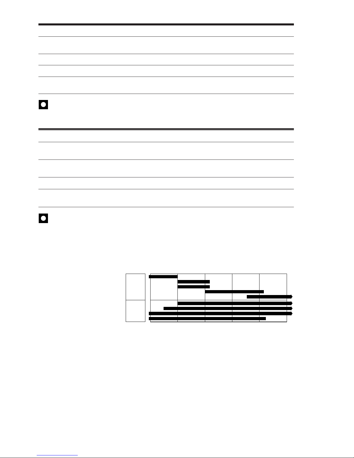
Olio motore
Un buon olio motore ha delle
particolari qualità. Fate uso
solamente di olio motore altamente
detergente, certificato sul
contenitore come corrispondente, o
superiore, alle necessità di servizio
SE, SF o SG.
Viscosità
SAE 10W-40
Le altre viscosità indicate in tabella
possono essere usate se la
temperatura media della zona di uso
della motocicletta si trova nei limiti
della gamma indicata.
40
–10
14
Uni
grade
Multi
grade
0
32
10
50
20
68
30
86
40°C
104°
F
20W–40 20W–50
15W–40 15W–50
10W–40
10W–30
10W
20W
20
30
Engine oil
Use a good engine oil as specified.
Use a highly detergent engine oil
only, as certified on the container,
with SE, SF or SG, or even higher,
service ratings.
Oil viscosity
SAE 10W-40
Other viscosity grades can be used
where the average ambient
temperatures are within the limits
shown.
Page 27
Generalità / Description 27
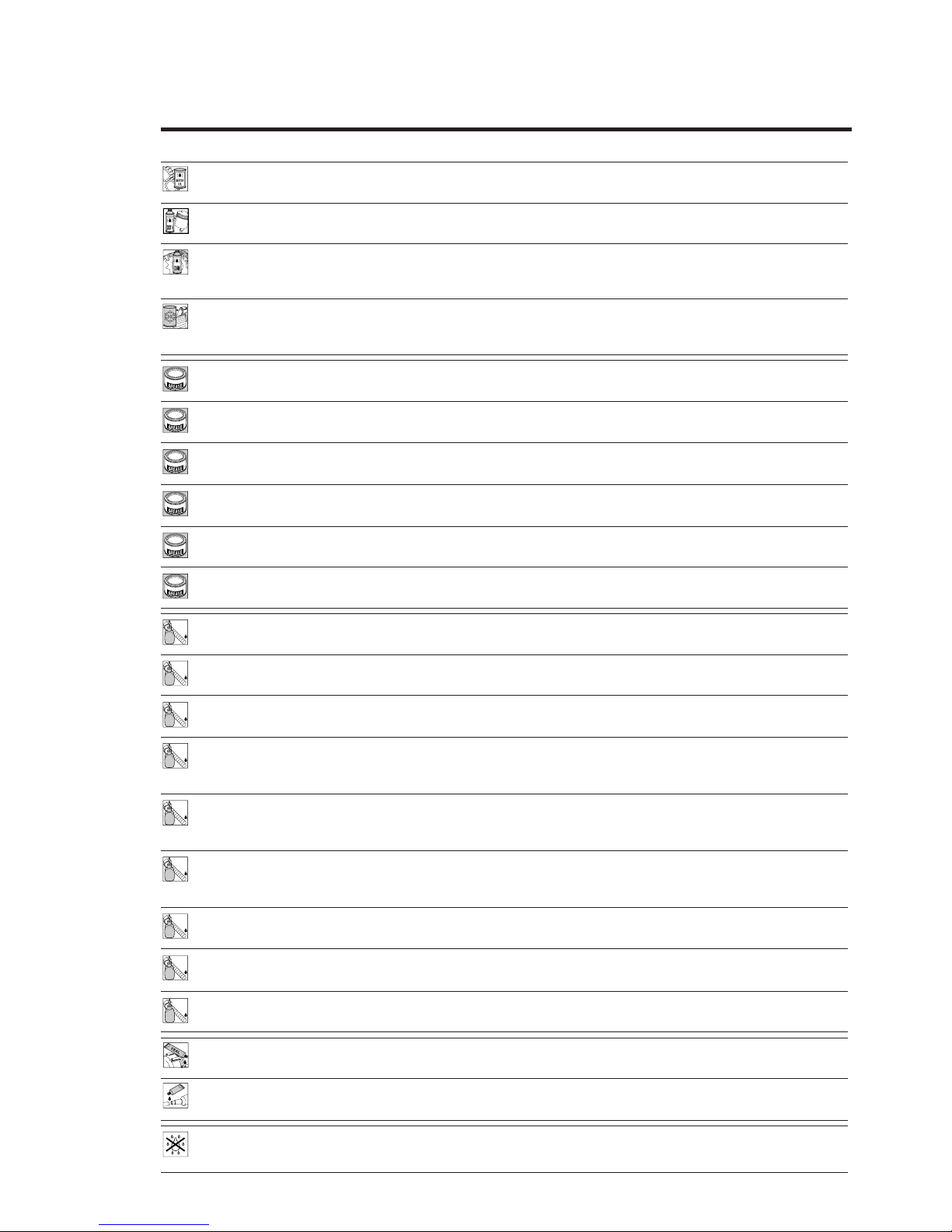
CARATTERISTICHE PRODOTTI
I prodotti usati per il serraggio, la sigillatura e la lubrificazione degli elementi verranno rappresentati all'interno della
figura con un simbolo. La tabella riporta i simboli utilizzati e le caratteristiche relative ai vari prodotti.
Simbolo Caratteristiche Prodotto consigliato
Olio motore (per caratteristiche vedi a pag. 26). SHELL
Advance Ultra 4
Liquido speciale per sistemi idraulici DOT 4. SHELL
Advance Brake DOT 4
Olio per ingranaggi SAE 80-90 o prodotti specifici per catene SHELL
con anelli OR. Advance Chain o
Advance Teflon Chain
Liquido antigelo (totalmente assente da nitriti, ammine e fosfati) SHELL
35÷40% + acqua. Advance coolant o
Glycoshell
GREASE A Grasso a base di litio, a fibra media, di tipo "multipurpose". SHELL Alvania R3
GREASE B Grasso al bisolfuro di molibdeno resistente ad estreme sollecitazioni SHELL
meccaniche e termiche. Retinax HDX2
GREASE C Grasso per cuscinetti e articolazioni sottoposti a prolungate SHELL
sollecitazioni meccaniche. Temperatura di utilizzo da –10 a 110 °C. Retinax LX2
GREASE D Grasso con proprietà protettive, anticorrosive e di idrorepellenza. SHELL
Retinax HD2
GREASE E Grasso PANKL - PLB 05.
GREASE F Grasso OPTIMOL - PASTE WHITE T.
LOCK 1 Frenafiletti a debole resistenza meccanica. LOCTITE 222
LOCK 2 Frenafiletti a media resistenza meccanica olio compatibile. LOCTITE 243
LOCK 3 Frenafiletti ad alta resistenza meccanica per sigillatura di parti filettate. LOCTITE 270
LOCK 4 Sigillante per piani ad alta resistenza meccanica e ai solventi. LOCTITE 510
Resiste ad alte temperature (fino a 200 °C), sigilla pressioni
fino a 350 Atm e colma giochi fino a 0,4 mm.
LOCK 5 Adesivo strutturale permanente per accoppiamenti cilindri a LOCTITE 128455
scorrimento libero o filettati su parti meccaniche. Alta resistenza
meccanica ed ai solventi. Temperatura di utilizzo da –55 a 175 °C.
LOCK 6 Sigillante di tubazioni e raccorderie medio-grandi, per acqua e ogni tipo LOCTITE 577
di gas (ad eccezione dell'ossigeno). Massima capacità di riempimento:
0,40 mm (gioco diametrale).
LOCK 7 Adesivo istantaneo gomma - plastica, con base etilica caricato LOCTITE 480
ad elastomeri.
LOCK 8 Bloccante permanente di parti filettate, cuscinetti, bussole, scanalati LOCTITE 601
e chiavette. Temperatura di esercizio da –55 a 150 °C.
LOCK 9 Frenafiletti a media resistenza meccanica. LOCTITE 401
Guarnizione liquida DUCATI Cod. 942470014
Pasta sigillante per tubi di scarico. Autosigillante si indurisce al calore
e resiste a temperature superiori a 1000 °C.
Spray impiegato nel trattamento degli impianti elettrici. Rimuove SHELL
umidità e condensa e offre alta resistenza alla corrosione. Idrorepellente. Advance Contact Cleaner
1
LOCK
2
LOCK
3
LOCK
4
LOCK
5
LOCK
6
LOCK
7
LOCK
8
LOCK
A
B
C
E
F
D
LOCK
9
Page 28
28 Generalità / Description
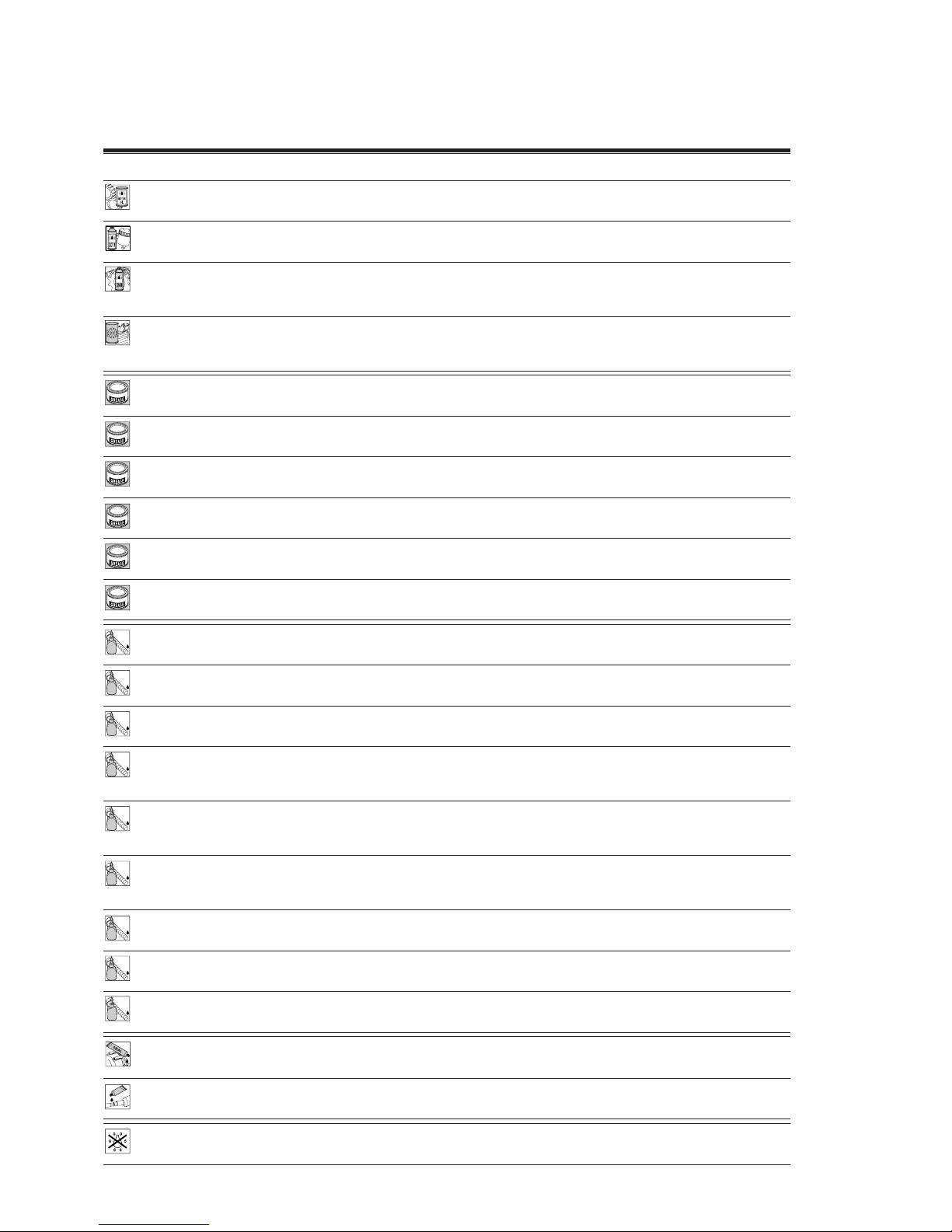
PRODUCT SPECIFICATIONS
Symbols inside the diagram show the type of threadlocker, sealant or lubricants to be used at the points indicated.
The table below shows the symbols together with the specifications for the threadlockers, sealants and lubricants
to be used.
Symbol Specifications Recommended product
Engine oil (for specifications, see page 26). SHELL
Advance Ultra 4
DOT 4 special hydraulic brake fluid. SHELL
Advance Brake DOT 4
SAE 80-90 gear oil or special products for chains with O-rings. SHELL
Advance Chain or
Advance Teflon Chain
Anti-freeze (nitride, amine and phosphate free) SHELL
35-40% water solution. Advance coolant or
Glycoshell
GREASE A Multipurpose, medium fibre, lithium grease. SHELL Alvania R3
GREASE B Molybdenum disulphide grease, high mechanical stress and high SHELL
temperature resistant. Retinax HDX2
GREASE C Bearing/joint grease for parts subject to prolonged SHELL
mechanical stress. Temperature range: -10 to 110 °C. Retinax LX2
GREASE D Protective grease. Corrosion protectant, waterproof. SHELL
Retinax HD2
GREASE E PANKL grease PLB 05.
GREASE F OPTIMOL grease PASTE WHITE T.
LOCK 1 Low-strength threadlocker. LOCTITE 222
LOCK 2 Oil-compatible medium-strength threadlocker. LOCTITE 243
LOCK 3 High-strength thread sealant for threaded parts. LOCTITE 270
LOCK 4 Flange sealant. Resistant to high mechanical stress, solvents and LOCTITE 510
high temperatures (up to 200 °C). For pressures up to 350 Atm.
Fills gaps up to 0.4 mm.
LOCK 5 Permanent adhesive for smooth or threaded cylindrical fasteners LOCTITE 128455
on mechanical parts. High resistance to mechanical stresses and
solvents. Temperature range: -55 to 175 °C.
LOCK 6 Pipe sealant for pipes and medium to large fasteners. For water LOCTITE 577
and gases (except oxygen). Maximum filling capacity: diameter
gaps up to 0.40 mm.
LOCK 7 Speed bonder for rubber and plastics. Elastomer loaded ethylic base. LOCTITE 480
LOCK 8 Retaining compound for threaded parts, bearings, LOCTITE 601
bushes, splines and keys. Temperature range: -55 to 150 °C.
LOCK 9 Medium-strength threadlocker LOCTITE 401
DUCATI liquid gasket - part no. 942470014
Exhaust pipe paste. Self-curing sealant, hardens when heated.
For temperatures over 1,000 °C.
Spray used in treating electrical systems to eliminate moisture and SHELL
condensation. Provides high resistance to corrosion. Waterproof. Advance Contact Cleaner
1
LOCK
2
LOCK
3
LOCK
4
LOCK
5
LOCK
6
LOCK
7
LOCK
8
LOCK
A
B
C
E
F
D
LOCK
9
Page 29

Manutenzione / Maintenance 29
Manutenzione
Maintenance
Page 30

30 Manutenzione / Maintenance
MANUTENZIONE PERIODICA
La longevità del motoveicolo,
l'ottimo stato di conservazione
generale, comprese le prestazioni,
sono in larga parte in funzione della
corretta manutenzione ordinaria e
del rispetto della periodicità
programmata, degli interventi
previsti.
È consigliabile pertanto, in
occasione della consegna del
motoveicolo nuovo, ricordare
all'acquirente di attenersi
scrupolosamente a quanto previsto
ed indicato sul manuale d'uso e
manutenzione, allegato al
motociclo. Informarsi inoltre,
dall'acquirente, sulle sue previsioni
di utilizzo della moto: tipologia di
guida preferenziale, lunghi percorsi
autostradali ad elevata velocità,
utilizzo prevalente in città, strade
polverose, strade di montagna o in
particolari condizioni climatiche:
temperatura troppo bassa o troppo
elevata, ecc...; formulare quindi, se
ritenuto necessario, un prontuario
personalizzato per il cliente sulla
base della tabella di manutenzione
programmata, riportata alla pagina
seguente.
ROUTINE MAINTENANCE
Routine, thorough maintenance will
ensure a long, trouble-free vehicle
life and will guarantee that the
motorcycle continues to give top
performance.
Therefore, when delivering a new
motorcycle, please recommend the
Owner to strictly follow the
indications given in the Owner’s
manual. Also ask the Owner what
are the expected riding conditions:
riding style, long, high-speed
motorway journeys, continuous city
use, very dusty roads, long
mountain trips, or extreme climates,
too high or too low temperatures,
etc... Then, prepare a customized
schedule, if necessary, based on the
maintenance schedule table on the
next page.
Page 31

Manutenzione / Maintenance 31
Operazioni Pre Dopo i Ogni Ogni Ogni Ogni
consegna primi 1000 km 10000 km 20000 km 30000 km
1000 km
Livello olio motore C C
Olio motore S S
Filtro olio motore S S
Filtro aspirazione olio motore C/P
Gioco valvole motore C
Cinghie distribuzione (1) CCS
Candele S
Livello liquido raffreddamento C
Sostituzione liquido raffreddamento S
Filtro carburante S
Corpo farfallato: sincronizzazione e minimo C
Filtro aria S
Pressione olio motore C
Compressione cilindri motore C
Olio comando freni e frizione C S
Comandi idraulici freni e frizione C C
Pneumatici: usura e pressione C C
Gioco cuscinetti sterzo C
Catena: tensionamento e lubrificazione C/L
Usura pastiglie freno C
Serbatoio carburante P
Sostituzione olio forcella ant. (1) S
Lubrificazione e ingrassaggio generale L
Controllo impianto ricarica batteria C C
Controllo serraggio punti critici per la C
sicurezza dinamica del veicolo (2)
Collaudo generale del veicolo (3) C
Pulizia generale P
Lettere identificazione operazione
C) Controllo e regolazione
L) Lubrificazione e/o ingrassaggio
P) Pulizia
S) Sostituzione
V) Verifica a motore avviato
Note
(1) Sostituire comunque ogni 2 anni.
(2) Controllare il serraggio dei seguenti componenti di sicurezza; in presenza di componenti non correttamente
serrati, fare riferimento alle tabelle delle coppie di serraggio riportate alla sezione Mototelaio e alla sezione
Motore.
(3) Il collaudo prevede la verifica dei seguenti componenti:
- Cuscinetti mozzi ruota
- Giunto elastico ruota posteriore
- Piastrino ferma pignone
- Cavalletto centrale e laterale
- Dispositivi di illuminazione e segnalazione
Page 32

32 Manutenzione / Maintenance
Operations Pre- After first Every Every Every Every
delivery 1,000 km 1,000 km 10,000 km 20,000 km 30,000 km
Engine oil level C C
Engine oil S S
Engine oil filter S S
Engine intake oil filter C/P
Valve clearance C
Timing belts (1) CCS
Spark plugs S
Coolant level C
Change coolant S
Fuel filter S
Throttle body: timing and idling C
Air filter S
Engine oil pressure C
Engine cylinder compression C
Clutch and brake fluid level C S
Clutch and brake hydraulic C C
controls
Tyres: wear and pressure C C
Steering bearing play C
Chain tension and lubrication C/L
Brake pad wear C
Fuel tank P
Change front fork oil (1) S
General lubrication L
Battery recharge system check C C
Checking tightening of vehicle C
safety-related critical points (2)
General testing (3) C
General cleaning P
Legend to maintenance operations
C) Check and adjust
L) Oil or grease
P) Clean
S) Change
V) Check with engine running
Note
(1) Replace every two years, in any case.
(2) Check the following safety components for proper tightening.
If not correctly tightened, refer to the torque setting tables indicated under Frame and Engine sections.
(3) Test the following components:
- wheel hub bearings,
- rear wheel rubber cush drive damper,
- sprocket stop plate,
- side and center stand,
- warning and lighting devices.
Page 33
Manutenzione / Maintenance 33
2 1
A
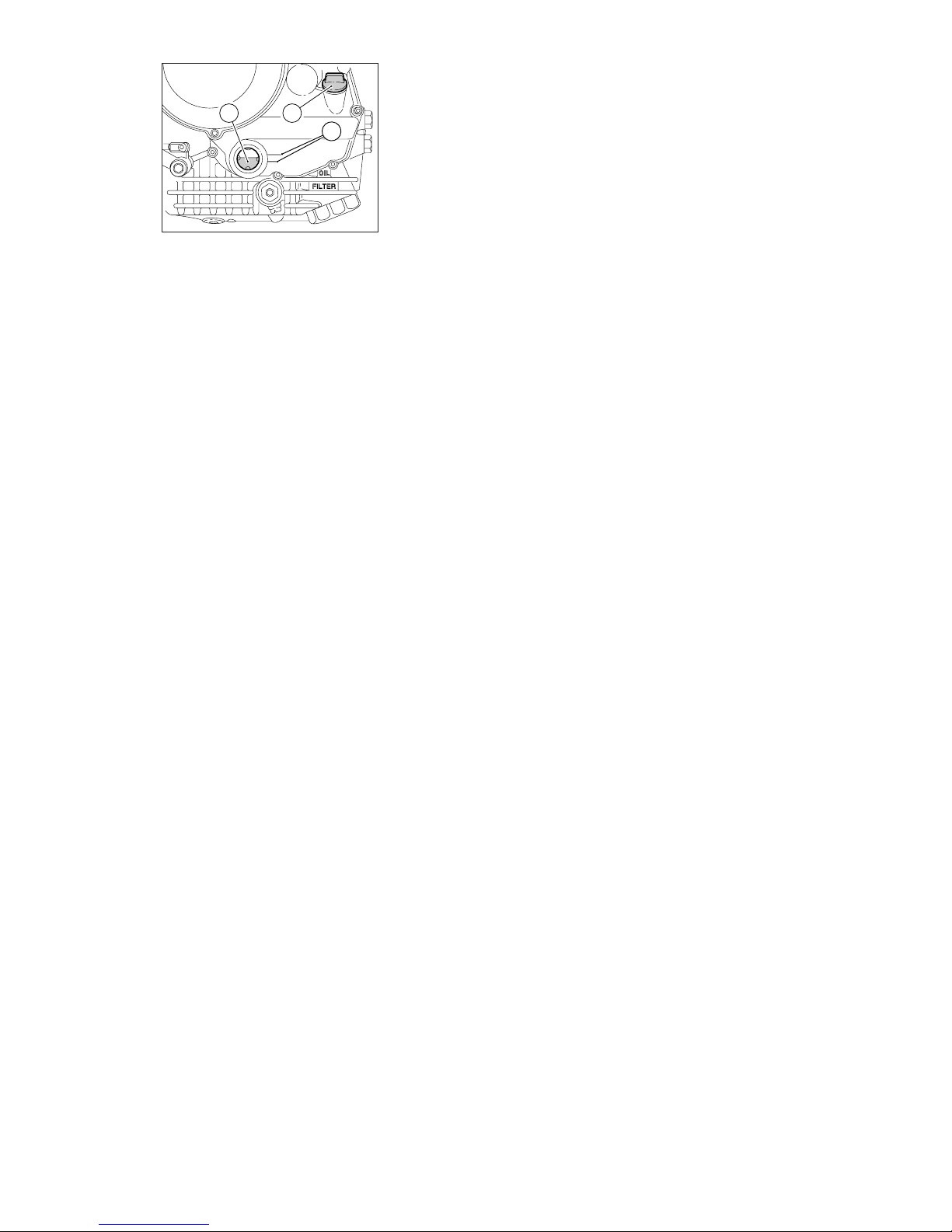
CONTROLLO LIVELLO
OLIO MOTORE
Il livello dell’olio nel motore è
visibile attraverso l’oblò (2) di
ispezione posto sul lato destro della
coppa olio.
❍
Attendete qualche minuto dopo
lo spegnimento affinché il livello si
stabilizzi.
❍
Controllare il livello con il veicolo
in posizione perfettamente verticale
e con motore caldo (ma spento).
❍
Il livello deve mantenersi tra le
tacche (A) segnate in
corrispondenza dell’oblò stesso.
❍
Se il livello risulta scarso è
necessario procedere al rabbocco.
❍
Rimuovere il tappo di carico (1) e
aggiungere olio prescritto fino a
raggiungere il livello stabilito.
❍
Rimontare il tappo.
CHECKING THE ENGINE OIL
LEVEL
Check the engine oil level on the
sight glass (2) on the RH side of the
oil sump.
❍
After switching off, allow the oil
to settle for several minutes before
checking the level.
❍
Check the level with the
motorcycle in vertical position and
with the engine hot (but off).
❍
The oil must be between the
notches (A) marked alongside the
sight glass.
❍
Top up in case of low oil level.
❍
Remove the filler plug (1) and top
up with the recommended oil.
❍
Refit the plug.
Page 34
34 Manutenzione / Maintenance
CONTROLLO PRESSIONE OLIO
MOTORE
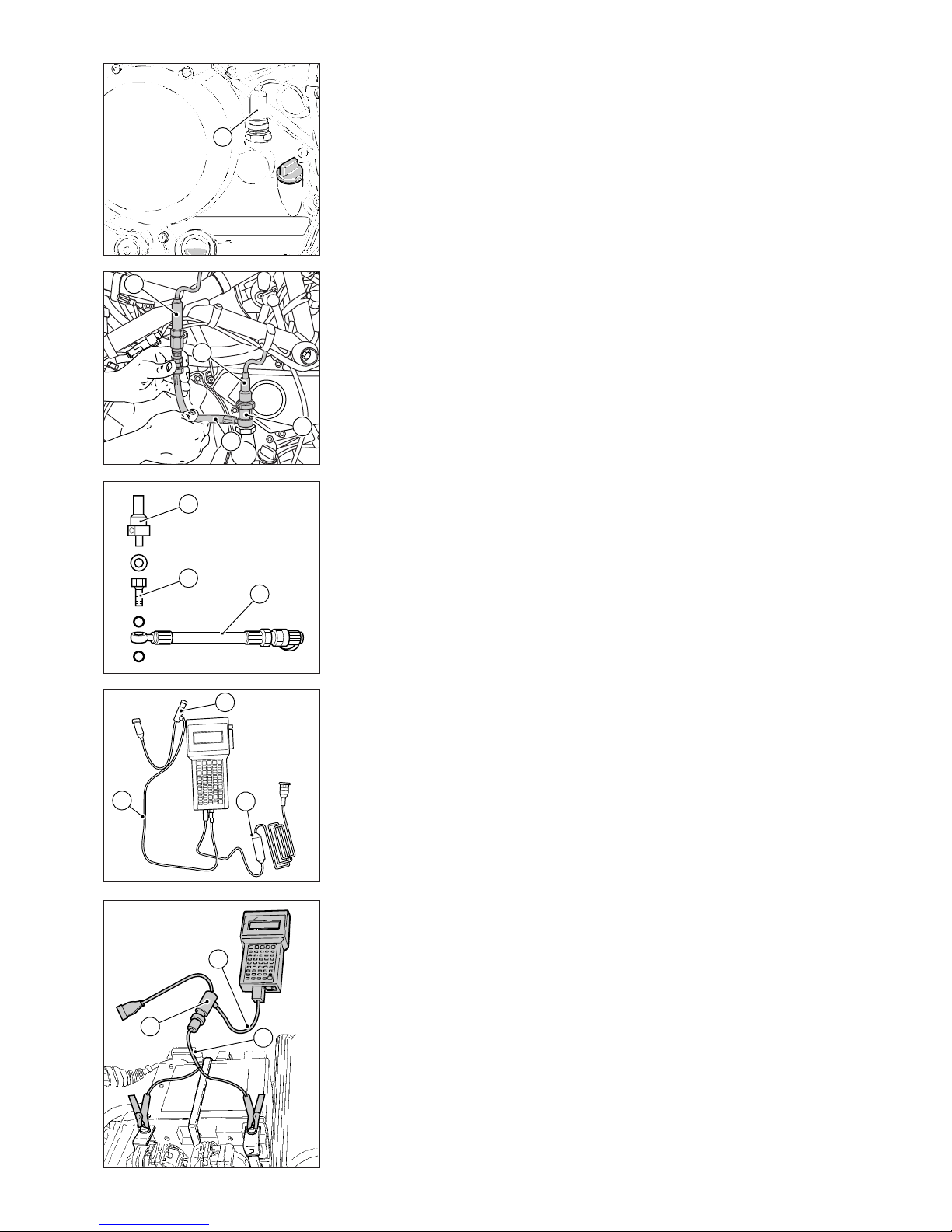
Per verificare la pressione olio
motore utilizzare il kit pressione olio
motore in dotazione allo strumento
di diagnosi Mathesis.
Rimuovere il pressostato (1),
facendo attenzione alla guarnizione.
Per collegare lo strumento,
impiegare il raccordo (2, cod.
814.1.114.1A) e il tubo (3, cod.
875.1.065.1A), forniti con il kit
pressione secondo la sequenza
indicata in figura.
Collegare il sensore pressione (4,
cod. 552.1.039.1A) al tubo (3)
pressione olio, per trasformare il
segnale di pressione in segnale
elettrico.
Collegare il cavo alimentazione (5,
cod. 514.1.034.1A) alla presa RC
586 (centrale) del Mathesis
utilizzando il cavo adattatore presa
batteria (6, cod. 514.1.038.1A) e
collegarlo alla presa A del cavo di
alimentazione e alla batteria della
moto.
Collegare il cavo di interfaccia (7,
cod. 514.1.032.1A) per ingresso
analogico alla presa COM2 del
Mathesis.
Seguire la procedura indicata nel
manuale dello strumento, al menù
“Pressione” della schermata
“Ausiliari”.
La pressione massima non deve
essere mai superiore a 6 bar.
Valori di controllo pressione olio:
●
Motore freddo:
1100÷1300 min
-1
.
maggiore di 2,5 bar
3500÷4000 min
-1
.
compreso tra 4 e 6 bar
●
Motore caldo:
1100÷1300 min
-1
.
maggiore di 1,1 bar
3500÷4000 min-1.
compreso tra 4 e 6 bar.
Una pressione troppo elevata può
significare un inceppamento della
valvola limitatrice. Al contrario, un
valore troppo basso può essere
causato dalla valvola limitatrice
bloccata nella posizione di apertura,
da una molla troppo tenera o da una
pompa difettosa. Altre cause
possono essere una usura
eccessiva delle guarnizioni di tenuta
o del motore stesso.
Terminato il controllo, rimuovere i
componenti del kit pressione e
rimontare il pressostato con
guarnizione sul motore.
Bloccarlo alla coppia prescritta.
CHECKING THE ENGINE OIL
PRESSURE
Check engine oil pressure using the
engine oil pressure kit coming with
the Mathesis tester.
Remove pressure switch (1). Keep
the seal.
Connect tester using union (2, part
No. 814.1.114.1A) and tubing (3,
part No. 875.1.065.1A) supplied
with the oil pressure kit. Follow the
sequence shown.
Connect pressure sensor (4, part
No. 552.1.039.1A) to oil pressure
tubing (3), in order to turn the
pressure signal into a power signal.
Using battery outlet adapter cable
(6, part No. 514.1.038.1A), connect
power cable (5, part No.
514.1.034.1A) to Mathesis RC586
(central) port and then connect it to
power cable A outlet and to
motorcycle battery.
Connect interface cable (7, part No.
514.1.032.1A) for pressure sensor
(4) analog inlet to Mathesis COM2
port.
Follow the procedure described
under “Pressure” menu of
“Auxiliary” display on the tester
manual.
Maximum pressure must never
exceed 6 bar.
Oil pressure check values:
●
Cold engine:
1,100-1,300 rpm.
over 2.5 bar
3,500-4,000 rpm.
between 4 and 6 bar
●
Hot engine:
1,100-1,300 rpm
over 1.1 bar
3,500-4,000 rpm
between 4 and 6 bar.
Too high a pressure may mean that
pressure relief valve has jammed.
Conversely, too low a pressure may
indicate that relief valve has
jammed in the open position or that
spring is too soft or pump faulty.
Problems with pressure may also
arise from worn seals or engine.
Once test is over, remove pressure
kit components and refit pressure
switch and seal on engine.
Tighten to the specified torque.
1
3
2
1
7
5
A
4
1
2
3
5
A
6
Page 35
Manutenzione / Maintenance 35
CHANGING THE ENGINE OIL
AND FILTER CARTRIDGE
Note
Change the oil when the
engine is hot (but off). In these
conditions the oil is more fluid and
will drain more rapidly and
completely.
❍
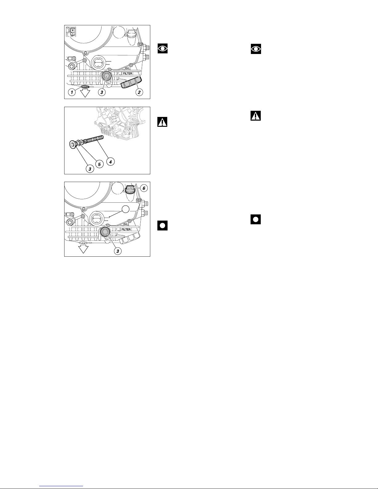
Remove the drain plug (1) from
the oil sump and allow the oil to
drain off.
Warning
Dispose of oil and/or filter
cartridges in compliance with
environmental protection
regulations.
▲
Remove any metallic deposits
from the end of the magnetic drain
plug. Refit the drain plug complete
with seal to the sump.
▲
Tighten to the specified torque.
❍
Using the special tool (part no.
0675.03.210 - available from Ducati
Spare Parts Dept.) or a standard filter
wrench, remove the filter cartridge
(2) from the oil sump.
Caution
Do not reuse cartridges.
▲
Grease the filter seal with engine
oil and then fit the new cartridge.
▲
Screw the cartridge into position
and then tighten to the specified
torque.
Every two oil changes, clean the oil
intake mesh filter.
❍
Undo the outer cap (3) and slide
out the mesh filter (4).
❍
Clean the mesh filter with fuel
and compressed air. Care must be
taken not to break the filter mesh.
▲
Refit the mesh filter (4) and its
seal (5) on the outer cap (3).
❍
Remove the filler plug (6) and fill
with the recommended oil (see
“Fuel and Lubricants” under
section “Description”). Fill until the
oil reaches the MAX (A) mark.
▲
Refit the filler plug. Run the
engine at idling speed for several
minutes.
▲
Check for oil leaks. Check that the
oil pressure light on the instrument
panel switches off after few
seconds when the engine is started.
If this is not the case, switch off and
trace the fault.
▲
Switch off the engine and allow
the oil to settle for several minutes.
Check the oil level and top up to the
Max. level where necessary.
▲
Refit all components previously
removed.
SOSTITUZIONE OLIO MOTORE
E CARTUCCIA FILTRO
Note
Questa operazione deve
essere eseguita a motore caldo
(motoveicolo spento) in quanto l’olio
in queste condizioni risulta più
fluido e la sua evacuazione è più
rapida e completa.
❍
Rimuovere il tappo di scarico (1)
dalla coppa motore e scaricare l’olio
usato.
Attenzione
Non disperdere l’olio usato e/
o le cartucce filtro nell’ambiente.
▲
Controllare che non vi siano
particelle metalliche attaccate alla
estremità magnetica del tappo di
scarico e riavvitarlo nella coppa con
la relativa guarnizione.
▲
Serrare alla coppia prescritta.
❍
Utilizzando la chiave speciale
(cod. 0675.03.210) disponibile
presso il servizio ricambi Ducati
oppure con una comune chiave per
filtri, rimuovere la cartuccia (2) filtro
olio dalla coppa.
Importante
Il filtro rimosso non può
essere riutilizzato.
▲
Montare una cartuccia nuova,
avendo cura di lubrificare con olio
motore la guarnizione.
▲
Avvitarla nella sua sede e
bloccarla alla coppia prescritta.
Ad ogni 2 cambi d’olio è
consigliabile pulire il filtro
aspirazione olio a rete.
❍
Svitare il tappo esterno (3) e svitare
l’elemento filtrante (4) e sfilarla.
❍
Procedere alla sua pulizia con aria
compressa e benzina facendo
attenzione a non lacerare la reticella.
▲
Rimontare il filtro a rete (4) e
relativa guarnizione (5) sul tappo (3).
❍
Rimuovere il tappo di carico (6) ed
effettuare il rifornimento con olio
del tipo prescritto (vedi tabella
“Rifornimenti” alla sezione
“Generalità”) fino a raggiungere il
livello MAX (A).
▲
Chiudere il tappo di carico e fare
funzionare il motore al minimo per
qualche minuto.
▲
Verificare che non ci siano perdite
di olio e che la lampada spia sul
cruscotto si spenga dopo qualche
secondo dall’accensione del motore.
In caso contrario fermare il motore
ed eseguire le opportune verifiche.
▲
Spegnere il motore e dopo
qualche minuto controllare che il
livello dell’olio corrisponda a quello
prescritto; se necessario ripristinare
il livello max.
▲
Rimontare le strutture rimosse.
A
Page 36
36 Manutenzione / Maintenance
SOSTITUZIONE FILTRO ARIA
Il filtro aria deve essere sostituito
agli intervalli prescritti sulla tabella
manutenzione periodica. Per
accedere alla scatola filtro è
necessario sollevare il serbatoio
carburante nel modo descritto al
capitolo “Sollevamento serbatoio
carburante” della sezione
“Mototelaio”.
Per rimuovere il filtro operare come
segue:
❍
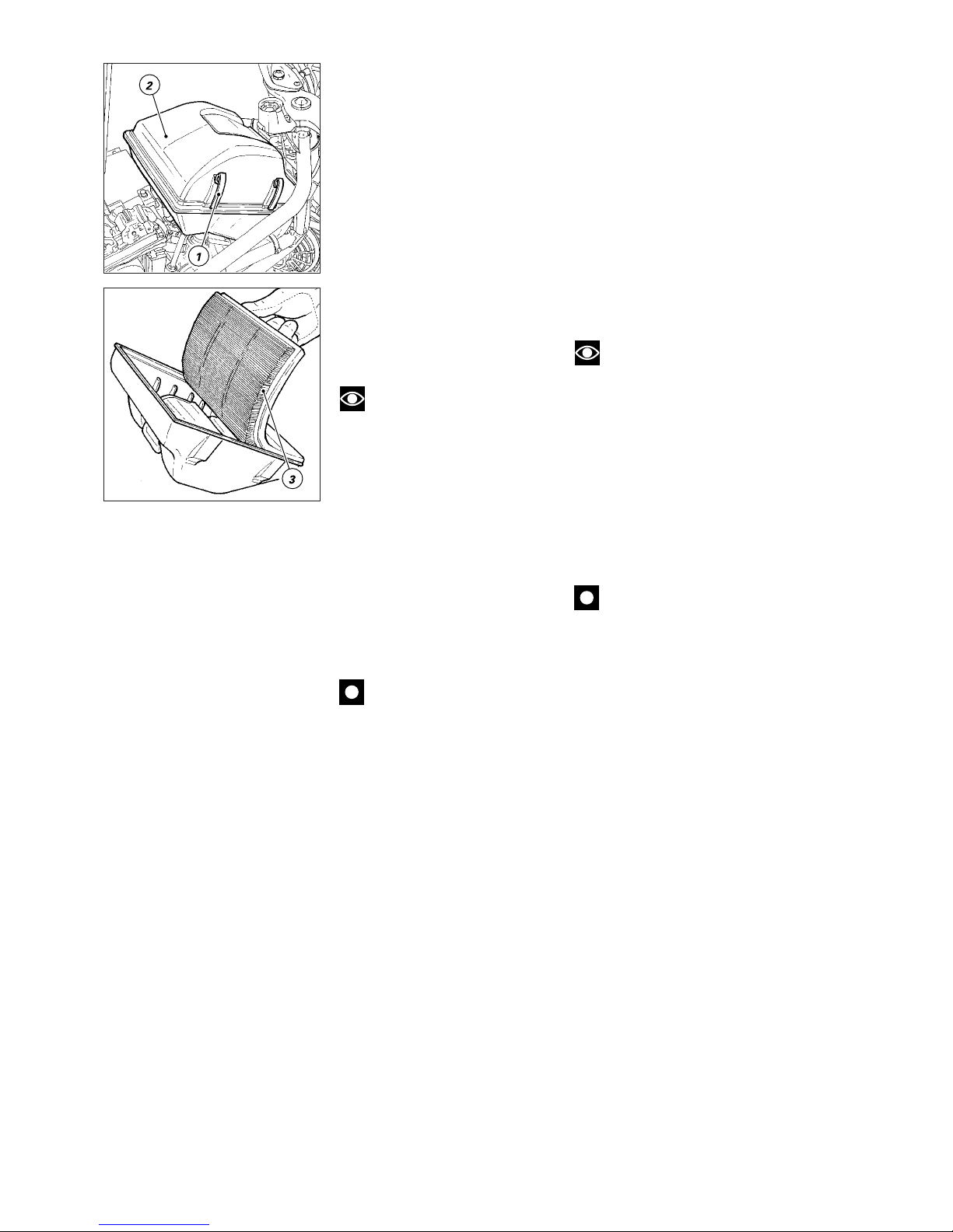
Sganciare le linguette (1) di
fissaggio del coperchio su entrambi
i lati della scatola filtro.
❍
Rimuovere il coperchio (2) con la
cartuccia filtro aria.
❍
Rimuovere la cartuccia filtro (3) dal
coperchio e sostituirla.
Note
Un filtro intasato, riduce
l’entrata dell’aria, riducendo la
potenza del motore e provocando
incrostazioni nelle candele. Non
usare il motociclo senza filtro. Le
impurità presenti nell’aria
potrebbero entrare nel motore
danneggiandolo.
▲
Il filtro nuovo va montato in modo
che le alette risultino orientate
trasversalmente al senso di marcia.
▲
Reinstallare correttamente la
cartuccia filtro (3) nella sede interna
al coperchio scatola filtro (2) e
rimontare tutti gli elementi e la
struttura rimossa.
Importante
In caso di impiego su strade
particolarmente polverose o umide
provvedere alla sostituzione più
frequentemente di quanto
prescritto.
CHANGING THE AIR FILTER
The air filter must be changed at the
intervals indicated in the routine
maintenance schedule. To reach
the filter box, raise the fuel tank as
described in “Raising the fuel tank”
under section “Frame”.
To remove the filter, proceed as
follows:
❍
Release the cover retaining
clips (1) on both sides of the
filter box.
❍
Remove the cover (2) with the air
filter cartridge.
❍
Remove the filter cartridge (3)
from the cover and replace it.
Note
A clogged air filter will reduce
air intake and engine power and
foul the spark plugs. Do not run the
engine without the air filter.
Running the engine without a filter
will draw impurities into the engine
and may damage the engine.
▲
Fit the new filter with fins
transverse to the vehicle direction
of travel.
▲
Fit the filter cartridge (3) inside
the filter box cover (2) and refit all
components previously removed.
Caution
If the vehicle is used in very
damp or dusty conditions, the air
filter cartridge must be changed
more frequently.
Page 37
Manutenzione / Maintenance 37
CHECKING THE CYLINDER
COMPRESSION
The performance and efficiency of
an engine are directly linked to the
compression inside the combustion
chambers of the two cylinders.
Compression which is too high/ low
or a large compression difference
between the two cylinders will
cause a drop in engine performance
and can cause engine breakdowns.
To check the compression you will
require a suitable compression
tester (e.g. MOTOMETER or similar)
and an adapter for fitting the tester
to the spark plug hole.
❍
Check that the battery is charged.
Under no-load conditions, there
must be a charge of at least 12.5 V
measured at the terminals.
❍
Start the engine and allow it to
warm up. Wait until the electric fan
switches on at least once.
❍
Stop the engine.
❍
Remove the spark plugs. Wear
safety gloves.
Warning
To prevent sparks, earth the
spark plug cable.
❍
Screw the adapter into the spark
plug hole of the cylinder to be
tested and connect the tester.
❍
Open the throttles fully.
❍
Turn the engine over using the
starter motor until the pressure
reading stops rising.
●
Check the compression of both
cylinders.
- Standard compression: 9-11 bar
- Minimum compression: 8 bar
- Maximum permitted compression
difference between cylinders: 2
bar
Excessively high compression
readings indicate the following:
- deposits in the combustion
chamber.
Low compression readings indicate:
- gas leakage between head and
cylinder;
- worn valve seats;
- worn valve guides;
- bent valve stems;
- incorrect valve clearances;
- worn cylinders or piston rings.
CONTROLLO COMPRESSIONE
CILINDRI MOTORE
Il rendimento del motore è
direttamente correlato con il valore
di pressione che si può misurare
nelle camere di combustione dei
due gruppi termici. Una pressione
eccessiva od insufficiente, così
come una eccessiva differenza tra i
due cilindri, produce sicuramente
un calo prestazionale del motore e
può essere causa di rotture.
Per effettuare questo controllo è
necessario disporre di uno
strumento di misura adatto
(MOTOMETER o analoghi), munito
di adattatore per l'installazione nella
sede candela.
❍
Verificare che la batteria risulti
carica (almeno 12,5 V rilevati
direttamente sui terminali, senza
carico).
❍
Riscaldare il motore lasciandolo
in funzione fino all'inserimento,
almeno una volta,
dell'elettroventola.
❍
Spegnere il motore.
❍
Rimuovere le candele, utilizzando
guanti contro le scottature.
Attenzione
Mettere a massa il cavo della
candela per evitare la produzione di
scintille.
❍
Avvitare nella sede del cilindro da
controllare l'adattatore e collegare lo
strumento di misura.
❍
Aprire completamente le farfalle.
❍
Far girare il motore con il
motorino avviamento fino al punto
in cui la pressione non aumenta più.
●
Controllare la pressione in ogni
cilindro:
- valore standard: 9÷11 bar;
- valore minimo: 8 bar;
- differenza massima accettabile tra i
cilindri: 2 bar.
Un valore di pressione eccessivo
può essere causato da:
- incrostazioni presenti nella camera
di combustione.
Un valore di pressione troppo basso
può essere causato da:
- perdite di gas tra testa e cilindro;
- sedi valvola usurate;
- guida valvole usurate;
- steli valvola distorti;
- gioco valvole scorretto;
- cilindro o segmenti usurati.
Page 38
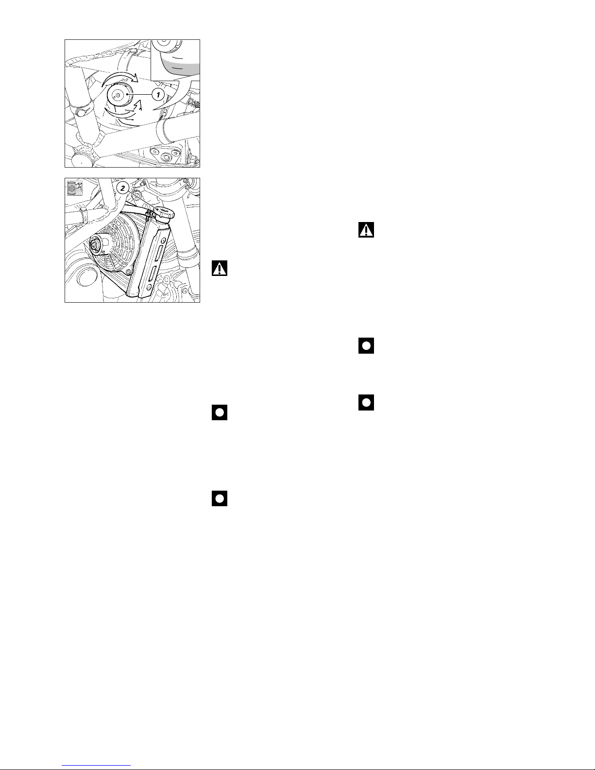
38 Manutenzione / Maintenance
CHECKING THE COOLANT
LEVEL
Check the coolant level in the
expansion tank – on the RH side of
the motorcycle - at the intervals
indicated in the “Routine
maintenance” chart. The tank is also
visible when seated in the riding
position.
●
The correct coolant level must be
10 mm above the MIN mark and
must not exceed the MAX mark.
In case of low level, top up with the
recommended coolant.
❍
Remove the filler cap (1) and top
up to the specified level.
▲
Refit the cap and the cover.
Warning
Risk of burns. Do not top up
the coolant through the cooler filler
cap (2) when the engine is still hot.
For optimal operating conditions
(down to –20 °C that is mixture
freezing point), use the following
coolant / water concentration:
●
ANTI-FREEZE: 35-40% of volume;
●
WATER: 65-60% of volume.
Caution
Very hard water rich in mineral
salts can damage the engine.
Increase the amount of anti-freeze
to 55% in case of very cold climates.
Caution
Coolant solutions with less
than 30% of anti-freeze will not
provide sufficient protection against
corrosion.
CONTROLLO LIVELLO LIQUIDO
REFRIGERANTE
Agli intervalli prescritti nella tabella
manutenzione periodica controllare
il livello del liquido refrigerante
contenuto nel serbatoio di
espansione, sul lato destro del
veicolo. Esso è visibile anche dal
posto di guida.
●
Il livello corretto deve risultare
10 mm sopra al riferimento MIN e
non oltrepassare il riferimento
MAX.
Se il livello risulta basso è
necessario provvedere al rabbocco
aggiungendo liquido prescritto.
❍
Svitare il tappo di carico (1) e
aggiungere liquido nuovo fino a
raggiungere il livello prescritto.
▲
Riavvitare il tappo e rimontare la
copertura rimossa.
Attenzione
Per nessun motivo
aggiungere liquido attraverso il
tappo di carico (2) del radiatore
quando il motore è ancora caldo.
Per ottenere le migliori condizioni di
esercizio (corrispondente all’inizio
congelamento miscela a –20 °C) il
liquido di raffreddamento prescritto
deve essere miscelato con acqua
nelle seguenti percentuali:
●
ANTIGELO: 35÷40 % del volume;
●
ACQUA: 65÷60 % del volume.
Importante
Un’acqua particolarmente
dura con alta percentuale di sali
minerali può danneggiare il motore.
In presenza di climi particolarmente
rigidi si può aumentare la
percentuale di anticongelante fino al
55% del volume.
Importante
Una soluzione con
percentuale di anticongelante
inferiore al 30% non fornisce una
adeguata protezione contro la
corrosione.
MAX
MIN
MAX
MIN
Close
Open
Page 39
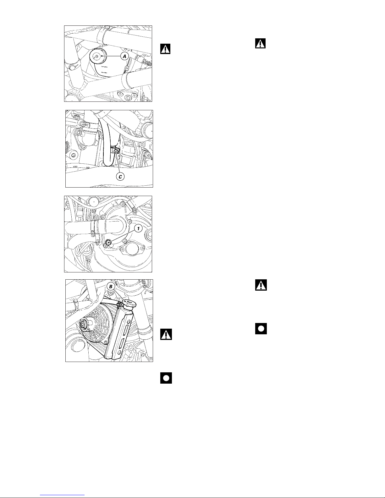
Manutenzione / Maintenance 39
CHANGING THE COOLANT
Warning
Change the coolant with cold
engine. Attempting to change
coolant with the hot engine involves
a risk of burns from hot coolant or
steam coming out.
❍
Undo the expansion tank filler cap
(A) and loosen the tie (C) on the
expansion tank – cooler hose.
❍
Slide out the hose from the cup
and allow the expansion tank to
drain off.
❍
Place a container under the
engine and place the motorcycle on
its side stand.
❍
Undo the plug (1) at pump cover
bottom.
❍
Slowly unscrew the radiator plug
(B).
❍
Allow the coolant to drain off
completely.
▲
Refit the plug (1) complete with
the new washer. Refit the hose to
the expansion tank and tighten the
tie (C).
▲
Fill the circuit with the
recommended fresh coolant until
the radiator is completely full.
▲
Allow several minutes for the
coolant to fill all internal ducts and
then start the engine.
●
Bring coolant to operating
temperature (103 °C) and let cooling
fan start at least once.
▲
Stop the engine and allow it to
cool down so that all the air comes
out of the cooling circuit.
Warning
Never move your hands or
clothing close to the fan, as it
operates automatically and can start
up at any time. Risk of being cut or
caught by the fan.
Caution
Check the cooling circuit for
possible leaks.
SOSTITUZIONE LIQUIDO
REFRIGERANTE
Attenzione
Questa operazione va
effettuata a motore freddo. Questa
operazione eseguita a motore caldo
può causare fuoriuscite di
refrigerante o di vapori bollenti che
possono procurare gravi ustioni.
❍
Svitare il tappo di carico (A) del
serbatoio di espansione e allentare
la fascetta (C) sulla tubazione di
collegamento serbatoio di
espansione-radiatore.
❍
Sfilare detta tubazione dalla
vaschetta e scaricare il liquido dal
serbatoio di espansione.
❍
Sistemare un recipiente sotto al
motore e porre il veicolo in
appoggio sul cavalletto laterale.
❍
Svitare il tappo (1) posto nella
parte inferiore del coperchio pompa
acqua.
❍
Svitare lentamente il tappo (B) dal
radiatore.
❍
Lasciare defluire completamente
tutto il liquido.
▲
Riavvitare il tappo (1) con nuova
guarnizione e reinstallare la
tubazione rimossa sul vaso
espansione serrando la fascetta (C).
▲
Procedere al caricamento del
circuito versando liquido prescritto
nuovo nel radiatore fino a riempirlo
completamente.
▲
Attendere qualche minuto per
consentire al liquido di riempire
tutte le canalizzazioni interne, quindi
avviare il motore.
●
Portare il liquido di
raffreddamento alla temperatura di
esercizio (103 °C) e far avviare la
ventola almeno una volta.
▲
Lasciare raffreddare il motore per
permettere la fuoriuscita dell’aria
presente nel circuito.
Attenzione
Non avvicinare mani , attrezzi
e indumenti alla ventola in quanto
questa entra in funzione senza
preavviso automaticamente e può
procurare seri danni.
Importante
Verificare che non vi siano
perdite nel circuito.
MAX
MIN
Page 40
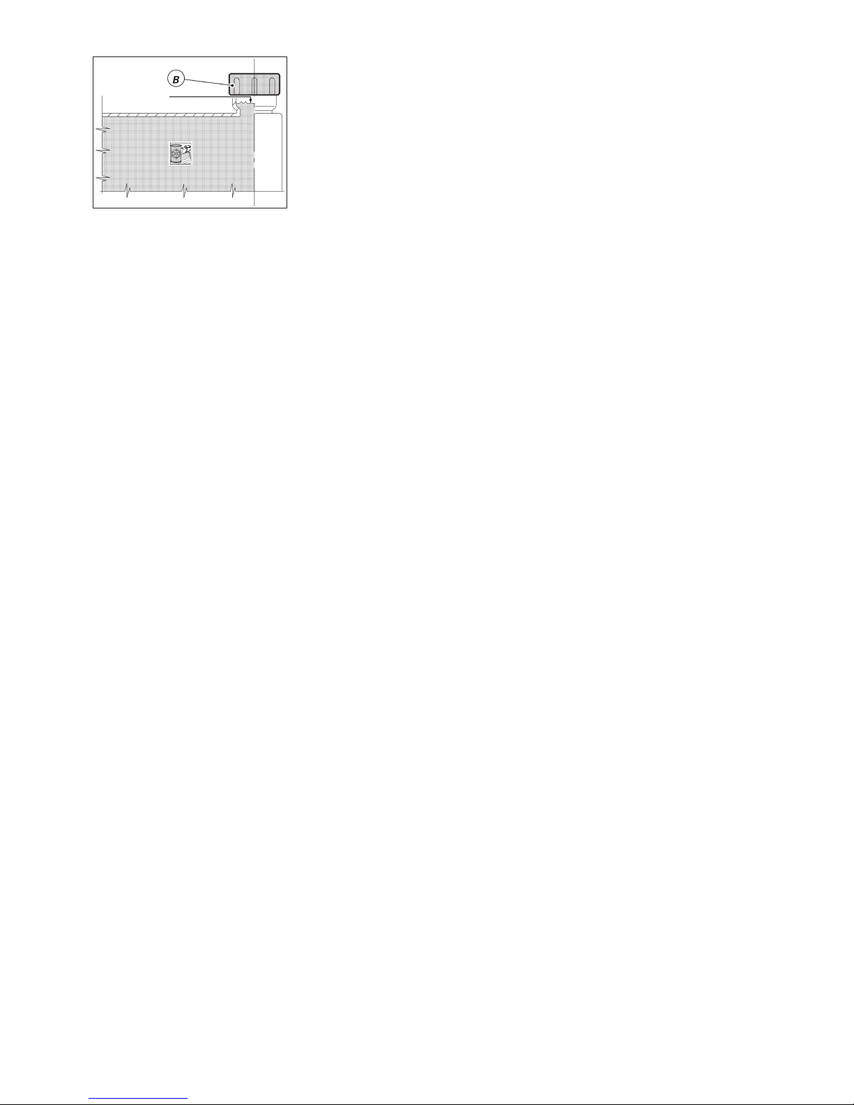
40 Manutenzione / Maintenance
Livello liquido
Coolant level
▲
Controllare che il radiatore risulti
completamente pieno;
eventualmente rabboccare.
▲
Serrare il tappo (B) del radiatore.
●
Completare il caricamento dal
bocchettone del serbatoio di
espansione, portando il livello del
liquido 10 mm sopra alla tacca
inferiore MIN.
▲
Chiudere il tappo (A) del
serbatoio di espansione e
rimontare tutte le strutture
rimosse.
▲
Make sure the cooler is full. Top
up if necessary.
●
Tighten the cooler cap (B).
▲
Fill the circuit through the
expansion tank filler until the
coolant level is 10 mm above the
MIN mark.
▲
Refit and tighten the expansion
tank filler cap (A) and refit all parts
previously removed.
Page 41
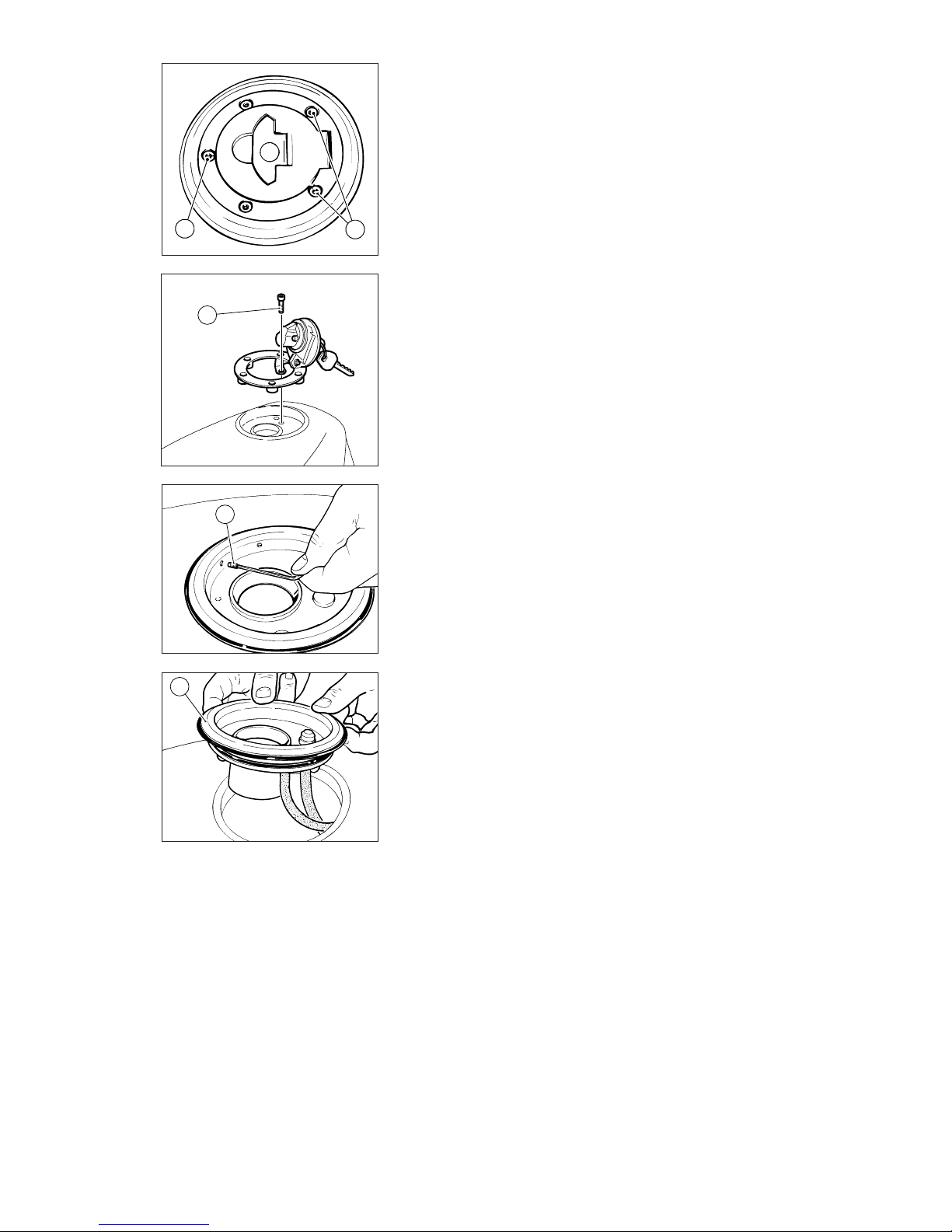
Manutenzione / Maintenance 41
A
A
C
D
B
SOSTITUZIONE FILTRO
CARBURANTE
Per la sostituzione del filtro
carburante operare come segue:
Smontaggio
❍
Svuotare il serbatoio carburante
❍
Svitare le tre viti (A) di fissaggio
del supporto tappo alla flangia del
serbatoio.
❍
Aprire il tappo e svitare la vite (B)
antifurto interna.
❍
Svitare i grani (C) di bloccaggio
della flangia (D) al serbatoio.
❍
Sollevare la flangia (D) con relativa
guarnizione, lasciandola collegata
alle tubazioni di sfiato e drenaggio.
❍
Operando all’interno del
serbatoio, allentare la fascetta (E) sul
tubo di collegamento al filtro
carburante.
❍
Sfilare il gruppo pompa-filtro dalla
apposita staffa di supporto.
❍
Staccare la connessione (F)
dell’indicatore livello carburante
dalla pompa.
❍
Allentare le fascette in
corrispondenza del filtro carburante.
❍
Sfilare il filtro (G) dalle tubazioni di
collegamento e sostituirlo.
CHANGING THE FUEL FILTER
To change the fuel filter, proceed as
follows:
Disassembly
❍
Drain the fuel off the tank.
❍
Unscrew the three screws (A) that
secure the filler cap assembly to the
tank flange.
❍
Undo the plug and unscrew the
inner anti-theft screw (B).
❍
Undo the grub screws (C) fixing
the flange (D) to the tank.
❍
Lift the flange (D) and seal leaving
the breather and drain tubes
connected.
❍
Working from inside the tank,
loosen the clip (E) on the fuel filter
hose.
❍
Slide the pump-filter assembly
out of the supporting bracket.
❍
Disconnect fuel sensor connector
(F) from the pump.
❍
Loosen the clips at the fuel filter.
❍
Slide the filter (G) out of the
connection hoses and fit a new
filter.
Page 42
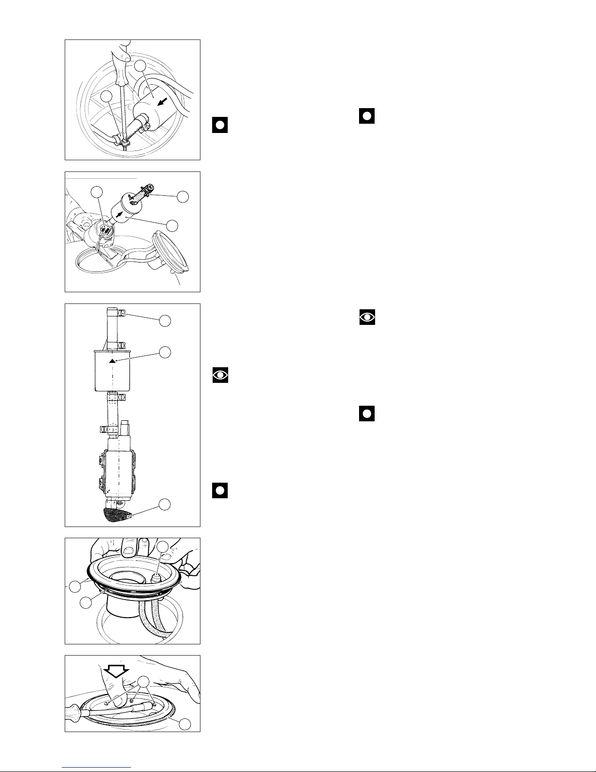
42 Manutenzione / Maintenance
Reassembly
▲
Before starting reassembly, clean
all parts thoroughly from any
possible deposit. Carefully blow
compressed air through the mesh
filter (H) on the pump inlet.
Caution
The pump intake mesh is very
thin. It might be easily damaged by
a strong jet of compressed air.
▲
Fit the new filter with the arrow
(L) stamped on the outer casing
pointing opposite the pump.
▲
When refitting the pump onto the
supporting bracket, make sure the
cables connecting pump to fuel
sensor are not squeezed in the
process.
▲
Arrange the clip (E) with the
screw facing the cap opening and
tighten to the specified torque.
▲
Grease the O-ring (M) and the lip
seal (N) on the flange and refit onto
the tank with the breather seal (P)
pointing back.
Note
Install the cap temporarily
using at least one screw to check
the mounting position of the flange
on the fuel tank.
▲
Push down on the flange to
locate the lip seal (N). Tighten the
grub screws (C) working crossways.
Caution
Do not overtighten the grub
screws (C).
▲
Refit the filler cap assembly and
tighten the screws (A) and (B) to the
specified torque.
Rimontaggio
▲
Prima del rimontaggio pulire
accuratamente tutti gli elementi da
eventuali depositi o incrostazioni e
soffiare con molta cautela aria
compressa sulla reticella di
aspirazione (H) della pompa.
Importante
La reticella di aspirazione della
pompa è di spessore molto sottile e
può essere danneggiata facilmente
con un getto di aria troppo violento.
▲
Quando si installa il filtro nuovo
disporlo con la freccia (L),
stampigliata sul contenitore
esterno, con direzione opposta alla
pompa.
▲
Quando si reinstalla la pompa
nella staffa di supporto, fare
attenzione a non schiacciare i cavi
del collegamento pompa-indicatore
di livello.
▲
Orientare la fascetta (E) con la vite
rivolta verso l’apertura del tappo e
serrarla alla coppia prescritta.
▲
Ingrassare opportunamente l’OR
di tenuta (M) e la guarnizione a
labbro (N) sulla flangia e installarla
nel serbatoio orientandola con il
gommino di sfiato (P) verso il
posteriore.
Note
Per verificare l’orientamento
corretto della flangia sul serbatoio,
installare provvisoriamente il tappo
e inserire almeno una vite di
fissaggio.
▲
Spingere sulla flangia per
assestare la guarnizione a labbro (N)
e serrare, procedendo a croce, i
grani (C).
Importante
Non serrare eccessivamente i
grani (C).
▲
Procedere al rimontaggio del
supporto del tappo bloccando alla
coppia prescritta le viti (A) e (B).
G
E
E
G
F
E
H
L
N
C
P
N
M
Page 43
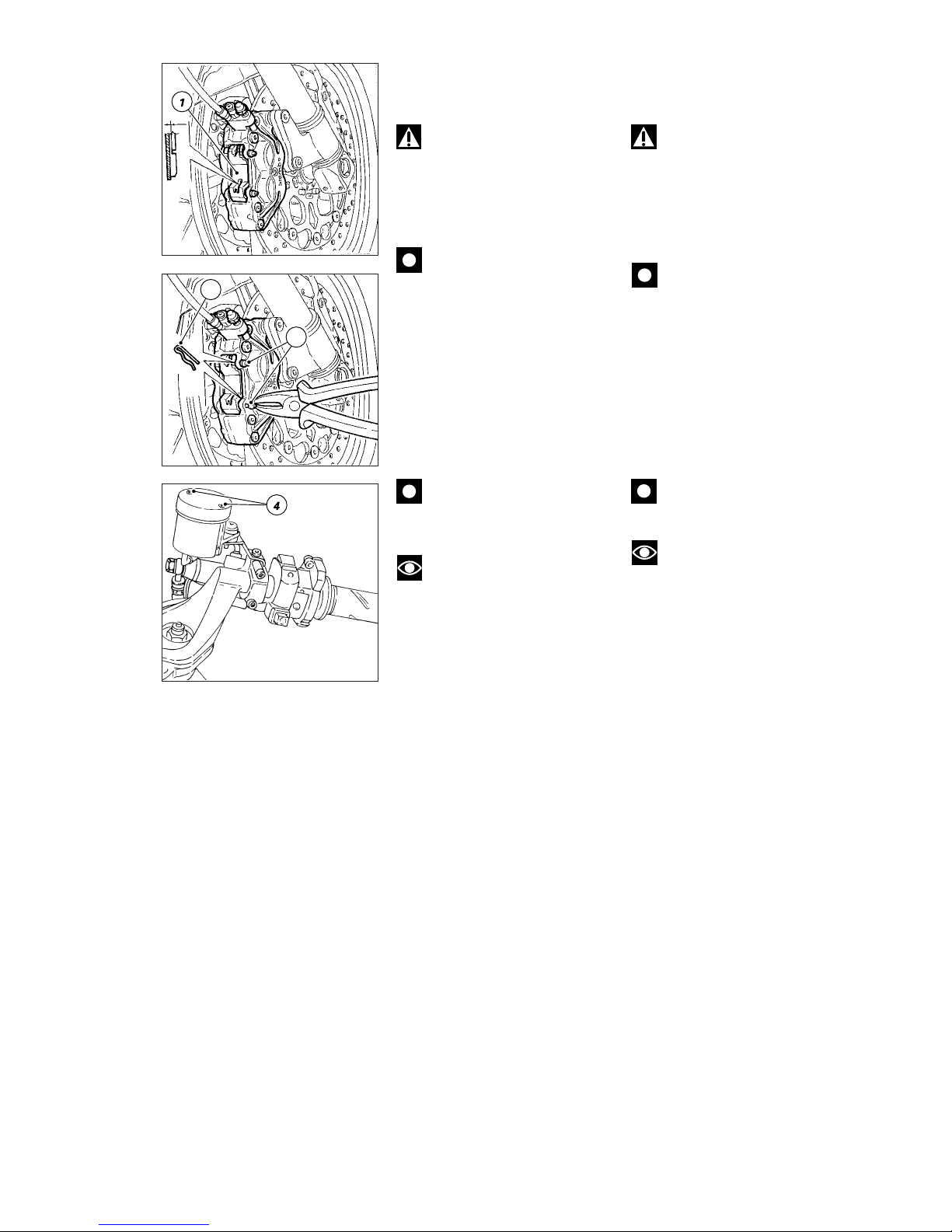
Manutenzione / Maintenance 43
CHECKING BRAKE PAD
WEAR. CHANGING BRAKE
PADS
Warning
Corrosion and irritant hazard.
Brake fluid is corrosive. Avoid
contact with eyes and skin. In the
event of accidental contact, wash
the affected part with abundant
quantities of running water and call
a doctor, if necessary.
Caution
Running in new pads. Please
inform the Customer that new pads
must be run-in carefully for the first
hundred kilometers to allow the
friction material to bed in
completely.
Front brake
❍
Check pad wear through the slot
on the caliper spring (1). The groove
between the two pads of friction
material must be visible.
Caution
If one of the pads is worn,
then change both pads.
Note
Change pads which are shiny
or vitrified.
To change the pads, proceed as
follows:
❍
Remove the spring clip (2) from
the pad retaining pins.
❍
Force the caliper pistons back
into their seats by forcing the brake
pads apart.
❍
Pull the pad retaining pins (3)
outwards and remove.
❍
Remove the pad retaining spring
(1) from between the two caliper
halves.
❍
Remove the worn pads.
▲
Insert the new pads and the
spring (1).
▲
Insert the centering pins and fix
them with the spring clips (2).
▲
Operate the brake lever
repeatedly so that the pads bed in
under the action of the brake fluid.
●
Check that the brake fluid level in
the master cylinder reservoir is
above the MIN mark.
If necessary, top up as follows:
❍
Turn the handlebar so that the
reservoir is level.
❍
Unscrew the two cross-headed
screws (4) and remove the reservoir
cover.
❍
Remove the inner membrane
from the reservoir.
CONTROLLO USURA E
SOSTITUZIONE PASTIGLIE
FRENO
Attenzione
Il liquido dell’impianto frenante
è corrosivo. A contatto degli occhi o
della pelle; lavare quindi
abbondantemente con acqua ed
eventualmente consultare un
medico.
Importante
Alla consegna del motoveicolo,
dopo la sostituzione delle pastiglie,
informare il cliente che per almeno
100 Km dovrà utilizzare il freno
anteriore con cautela, al fine di
consentire un corretto e completo
assestamento dei materiali d'attrito.
Freno anteriore
❍
Controllare attraverso la fessura
ricavata sulla molla (1) della pinza che
risulti visibile il solco ricavato sulla
superficie di attrito delle pastiglie.
Importante
Se anche una sola delle
pastiglie risulta usurata è
necessario sostituirle entrambe.
Note
Sostituire le pastiglie che
presentano un aspetto lucido o
“vetroso”.
Procedere alla sostituzione delle
pastiglie in questo modo:
❍
Rimuovere la copiglia di sicurezza
(2) dai perni tenuta pastiglie.
❍
Spingere i pistoncini della pinza
completamente dentro ai propri
alloggiamenti, divaricando le
pastiglie usurate.
❍
Sfilare i perni (3) di tenuta pastiglie
verso l’esterno.
❍
Rimuovere la molla (1) di tenuta
pastiglie posta tra le semipinze.
❍
Sfilare le pastiglie usurate.
▲
Inserire le pastiglie nuove e
relativa molla (1).
▲
Infilare i perni di centraggio e
bloccarli con le copiglie di sicurezza
(2).
▲
Azionare ripetutamente la leva del
freno per permettere l’assestamento
delle pastiglie sotto l’azione di spinta
del liquido freni.
●
Verificare che il livello nel
serbatoio della pompa non sia al di
sotto della tacca di MIN.
In caso contrario provvedere al
rabbocco procedendo come segue:
❍
Ruotare il semimanubrio per
livellare il serbatoio.
❍
Rimuovere il coperchio del
serbatoio svitando le due viti a
croce (4).
❍
Rimuovere la membrana dal
serbatoio.
2
3
Page 44
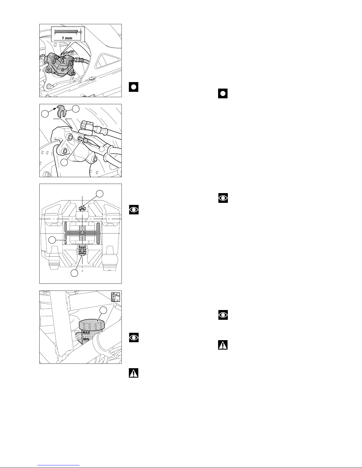
44 Manutenzione / Maintenance
❍
Top up to the max level using
the brake fluid specified.
▲
Reassemble all components
previously removed.
Rear brake
❍
Check through the slot between
the two caliper halves that there is
at least 1 mm of friction material on
the pads.
Caution
If one of the pads is worn,
then change both pads.
To change the pads, proceed as
follows:
❍
Remove the spring clip (2) (on caliper
inner side) from the pad retaining pin.
❍
Force the caliper pistons back into
their seats by forcing the brake pads
apart.
❍
Pull the pad retaining pin (1) outwards
and remove.
❍
Remove the pad retaining spring (3)
from between the two caliper halves.
❍
Remove the worn pads.
Note
Change pads which are shiny
or vitrified.
▲
Insert the new pads and the
spring (3).
▲
Insert the centering pin (1) and fix
it in place with the spring clip (2);
the safety tab (A) must be pointing
towards the wheel.
▲
Operate the brake pedal
repeatedly so that the pads bed in
under the action of the brake fluid.
●
Check that the brake fluid level in
the master cylinder reservoir is
between the MIN and MAX
marks. If this is not the case,
unscrew the reservoir cap (4) and
top up with brake fluid.
Note
Should pads be hard to
replace, undo fastening screws and
remove brake calipers.
Warning
Safety components. Follow
the procedure set forth under
section “Frame” and, at
reassembly, pay special attention to
brake calipers retaining screws
tightening torque.
A
2
1
4
2
3
1
❍
Rabboccare con liquido prescritto
fino al livello massimo.
▲
Rimontare i componenti rimossi.
Freno posteriore
❍
Controllare attraverso la fessura
ricavata tra le due semipinze che
risulti visibile almeno 1 mm di
materiale di attrito sulle pastiglie.
Importante
Se anche una sola delle
pastiglie risulta consumata sarà
necessario sostituirle entrambe.
Procedere alla sostituzione delle
pastiglie in questo modo:
❍
Rimuovere la copiglia di sicurezza
(2) (sul lato interno della pinza) dal
perno tenuta pastiglie.
❍
Spingere i pistoncini della pinza
completamente dentro ai propri
aloggiamenti, divaricando le
pastiglie usate.
❍
Sfilare il perno (1) di tenuta
pastiglie verso l’esterno.
❍
Rimuovere la molla (3) di tenuta
pastiglie posta tra le semipinze.
❍
Sfilare le pastiglie usurate.
Note
Sostituire le pastiglie che
presentano un aspetto lucido o
“vetroso”.
▲
Inserire le pastiglie nuove e
relativa molla (3).
▲
Infilare il perno di centraggio (1) e
bloccarlo con la copiglia di sicurezza
(2) orientando il bordino (A) verso la
ruota.
▲
Azionare ripetutamente il pedale
del freno per permettere
l’assestamento delle pastiglie sotto
l’azione di spinta del liquido freni.
●
Verificare che il livello del
serbatoio risulti compreso tra le
tacche di MIN e di MAX. In caso
contrario provvedere al rabbocco
dopo aver svitato il tappo (4) del
serbatoio.
Note
Se l'operazione di
sostituzione pastiglie dovesse
risultare difficoltosa, rimuovere le
pinze, svitando le viti di fissaggio.
Attenzione
Essendo le pinze freno un
organo di sicurezza della moto,
attenersi a quanto riportato alla
sezione "Mototelaio" ed in
particolare fare attenzione in fase di
rimontaggio alla coppia di serraggio
delle viti di fissaggio delle pinze.
Page 45
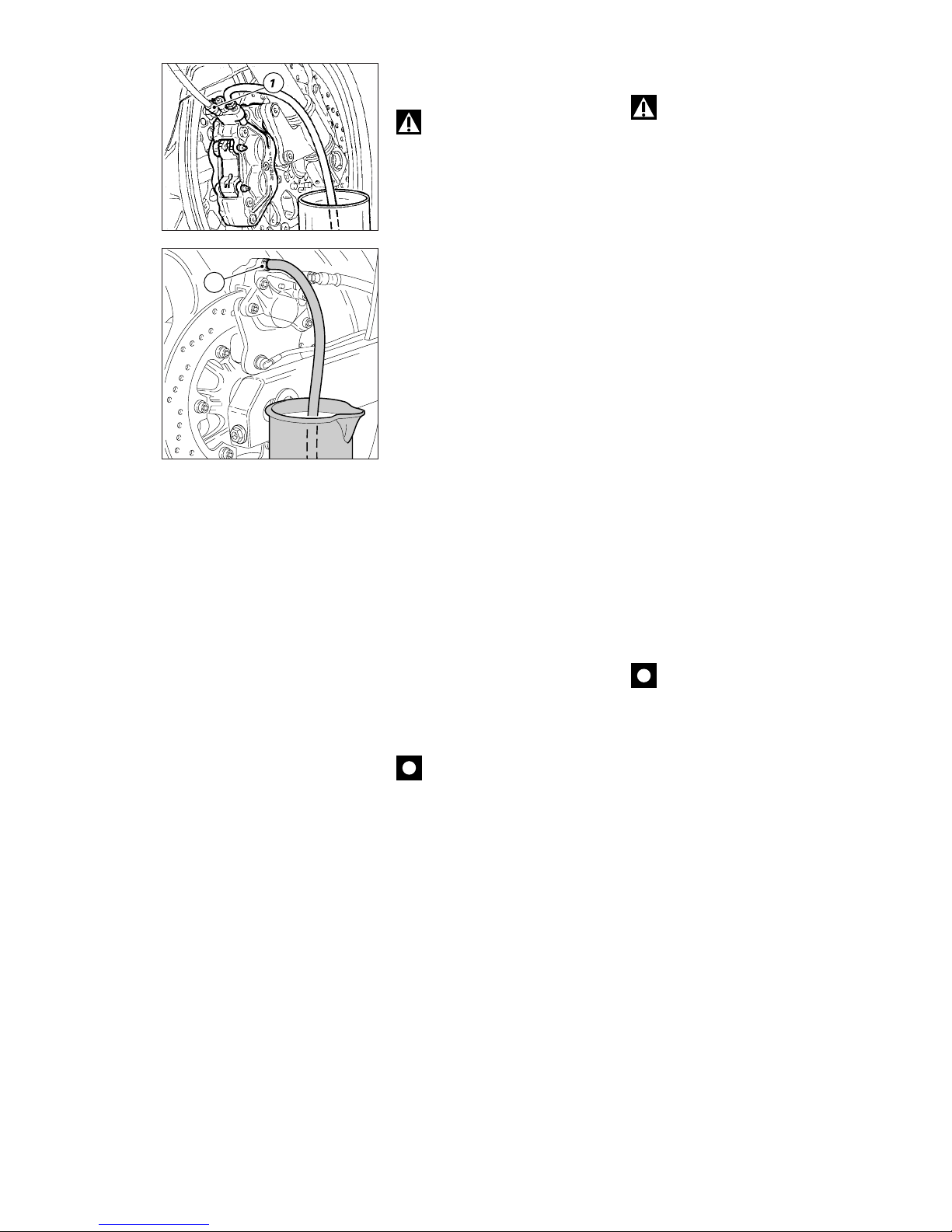
Manutenzione / Maintenance 45
CHANGING THE BRAKE FLUID
Warning
Corrosion and irritant hazard.
Brake fluid is corrosive. Avoid
contact with eyes and skin. In the
event of accidental contact, wash
the affected part with abundant
quantities of running water, if
necessary.
Draining the circuit
❍
Remove the cover with the
membrane from the brake fluid
reservoir.
❍
Connect a brake bleeder
(available on the market) to the
bleed valve (1 or 2) of the caliper.
❍
Unscrew the bleed valve and
pump with the bleeder until all fluid
has been drained out of the circuit.
❍
If a bleeder is unavailable,
connect a piece of transparent
plastic tubing to the caliper bleed
valve (1 or 2). Place the other end in
a container on the floor holding
used brake fluid.
❍
Unscrew the bleed valve by 1/4 of
a turn.
❍
Operate the brake lever (or pedal)
until all the fluid has been bled out
of the circuit.
❍
Repeat this operation on each
brake caliper.
Filling the circuit
▲
Fill the reservoir with specified
brake fluid from a new container.
Caution
During the next operation, the
fluid level must remain topped up at
all times. The end of the transparent
plastic tubing must remain
immersed in the discharged brake
fluid at all times.
▲
Operate the brake lever (or pedal)
several times to fill the circuit and
bleed the air.
▲
Connect the bleeder to the bleed
valve.
▲
Pump the bleeder and loosen the
bleed valve. Make sure the level
does not drop below MIN.
▲
Repeat the bleeding operation
until air bubbles no longer come out
of the plastic tube.
▲
Tighten the bleed valve to the
specified torque.
▲
If a bleeder is unavailable,
connect a piece of clear plastic
tubing to the bleed valve as
described for draining the circuit.
SOSTITUZIONE LIQUIDO
IMPIANTO FRENANTE
Attenzione
Il liquido impiegato
nell’impianto frenante, oltre a
danneggiare la vernice, è
dannosissimo a contatto degli occhi
o della pelle; lavare quindi
abbondantemente con acqua
corrente la parte interessata in caso
di accidentale contatto.
Scarico circuito
❍
Togliere il coperchio con
membrana dal serbatoio liquido freni.
❍
Collegare alla valvola di spurgo (1
o 2) della pinza uno spurgatore per
freni, comunemente reperibile in
commercio.
❍
Allentare la valvola di spurgo e
pompare con lo spurgatore fino a
quando non esce più fluido
dall’impianto.
❍
In caso di indisponibilità dello
spurgatore, collegare alla valvola di
spurgo (1 o 2) della pinza, un
tubicino in plastica trasparente e
immergerne l’estremità in un
contenitore appoggiato sul
pavimento e contenente liquido
freni usurato.
❍
Svitare di 1/4 di giro la valvola di
spurgo.
❍
Azionare la leva o il pedale
comando freno fino alla totale
fuoriuscita del liquido.
❍
Eseguire l’operazione per ogni
pinza freno.
Riempimento circuito
▲
Riempire il serbatoio con olio
prescritto prelevato da un
contenitore intatto.
Importante
Mantenere sempre a livello
l’olio dell’impianto durante tutta
l’operazione e lasciare l’estremità
del tubo trasparente sempre
immersa nel liquido scaricato.
▲
Azionare diverse volte la leva o il
pedale del freno per riempire
l’impianto e spurgare l’aria.
▲
Collegare alla valvola di spurgo lo
spurgatore.
▲
Pompare con lo spurgatore e
allentare la valvola di spurgo
verificando sempre che il livello non
scenda al di sotto del MIN.
▲
Ripetere quest’ultima fase fino a
quando, nel tubo trasparente
collegato alla valvola di spurgo, non
appaiono più bolle d’aria.
▲
Bloccare la valvola di spurgo alla
coppia prescritta.
▲
In caso di indisponibilità dello
spurgatore collegare alla valvola di
spurgo un tubicino in plastica
trasparente come descritto per lo
scarico dell’impianto.
2
Page 46
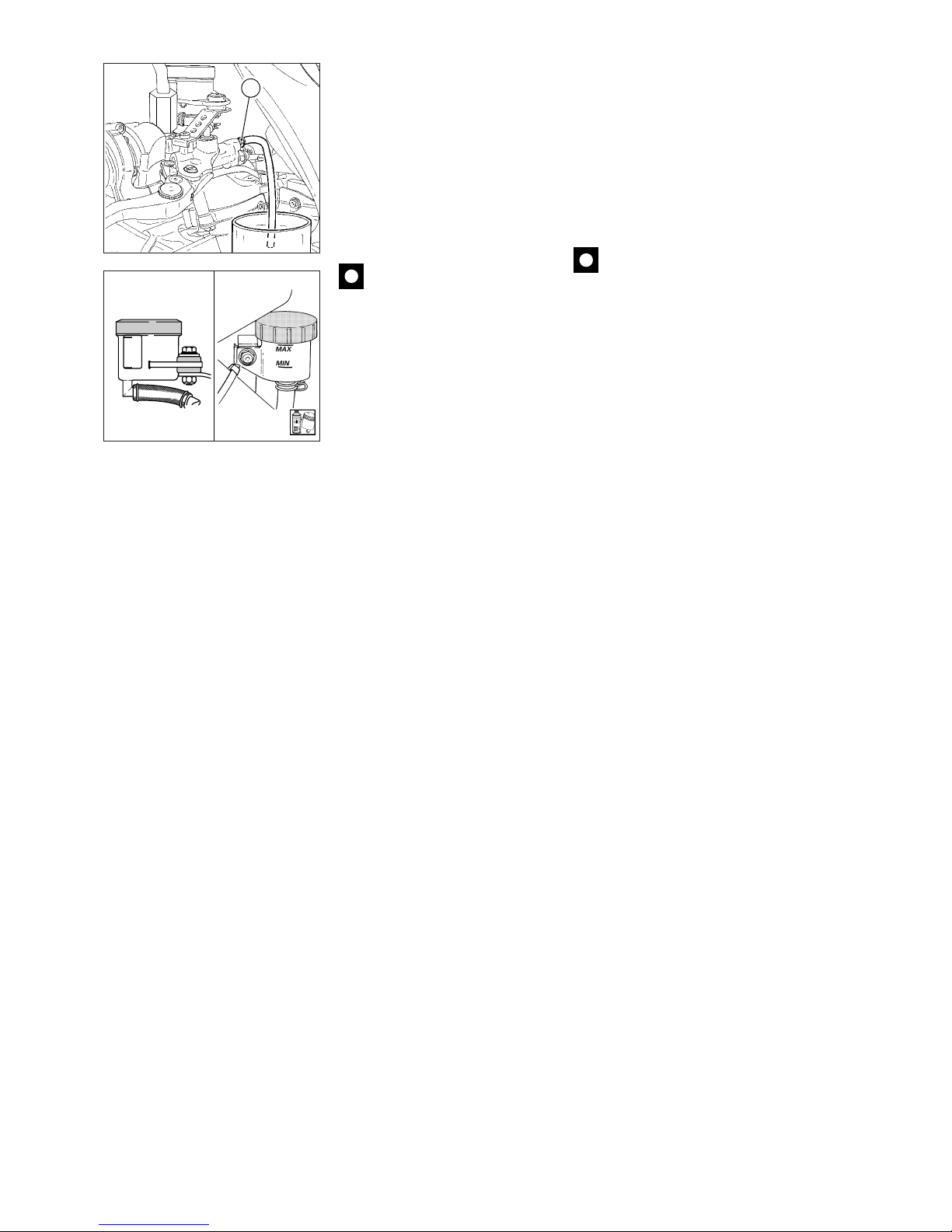
46 Manutenzione / Maintenance
▲
Unscrew the bleed valve 1/4 of a
turn and operate the brake lever or
pedal until fluid starts coming out of
the bleed valve.
▲
Pull in the lever or press down
the pedal all the way and then
loosen the bleed valve by at least
1/4 of a turn.
▲
Wait a few seconds; release the
brake lever (or pedal) gradually while
closing the bleed valve.
Caution
Do not release the brake lever
(or pedal) until the bleed valve has
been fully tightened.
▲
Repeat the bleeding operation
until no air bubbles come out of the
plastic tube.
▲
Bleed the bleed valves one at a
time.
▲
Tighten the bleed valve to the
specified torque. Fit the dust cap to
the bleed valve.
▲
To bleed all the air which might
remain at the front brake master
cylinder top, follow the same
procedure for the bleed valve (3).
▲
Top up the brake fluid in the
reservoir. Refit all the parts removed
previously.
Note for the rear brake
▲
Refit the caliper and the tube
with the proper clamp.
▲
Tighten the screws on the rear
brake caliper to the specified torque
(see “Tightening torque figures” in
section “Frame”).
MAX
MIN
2
▲
Aprire la valvola di spurgo di 1/4
di giro e azionare la leva o il pedale
del freno fino a quando inizierà ad
uscire fluido dalla valvola di spurgo.
▲
Tirare completamente la leva o il
pedale e poi allentare la valvola di
spurgo di almeno 1/4 di giro.
▲
Attendere qualche secondo;
rilasciare lentamente la leva o il
pedale e chiudere
contemporaneamente la valvola di
spurgo.
Importante
Non rilasciare la leva o il
pedale del freno se la valvola non è
ben serrata.
▲
Ripetere l’operazione finché dal
tubicino in plastica uscirà liquido
privo di bollicine d’aria.
▲
Compiere l’operazione di spurgo
agendo su una valvola per volta.
▲
Bloccare alla coppia prescritta la
valvola di spurgo e installare il
cappuccio di protezione.
▲
Per eliminare completamente
l’aria che può rimanere nel punto
più alto della pompa freno anteriore,
agire allo stesso modo sulla valvola
di spurgo (3).
▲
Livellare il liquido nel serbatoio e
rimontare gli elementi rimossi.
Nota per freno posteriore
▲
Rimontare la pinza freno e fissare
il tubo con l'apposita staffetta.
▲
Bloccare le viti di fissaggio della
pinza freno posteriore alla coppia
prescritta (vedi capitolo "Coppie di
serraggio" alla sezione "Mototelaio").
Page 47
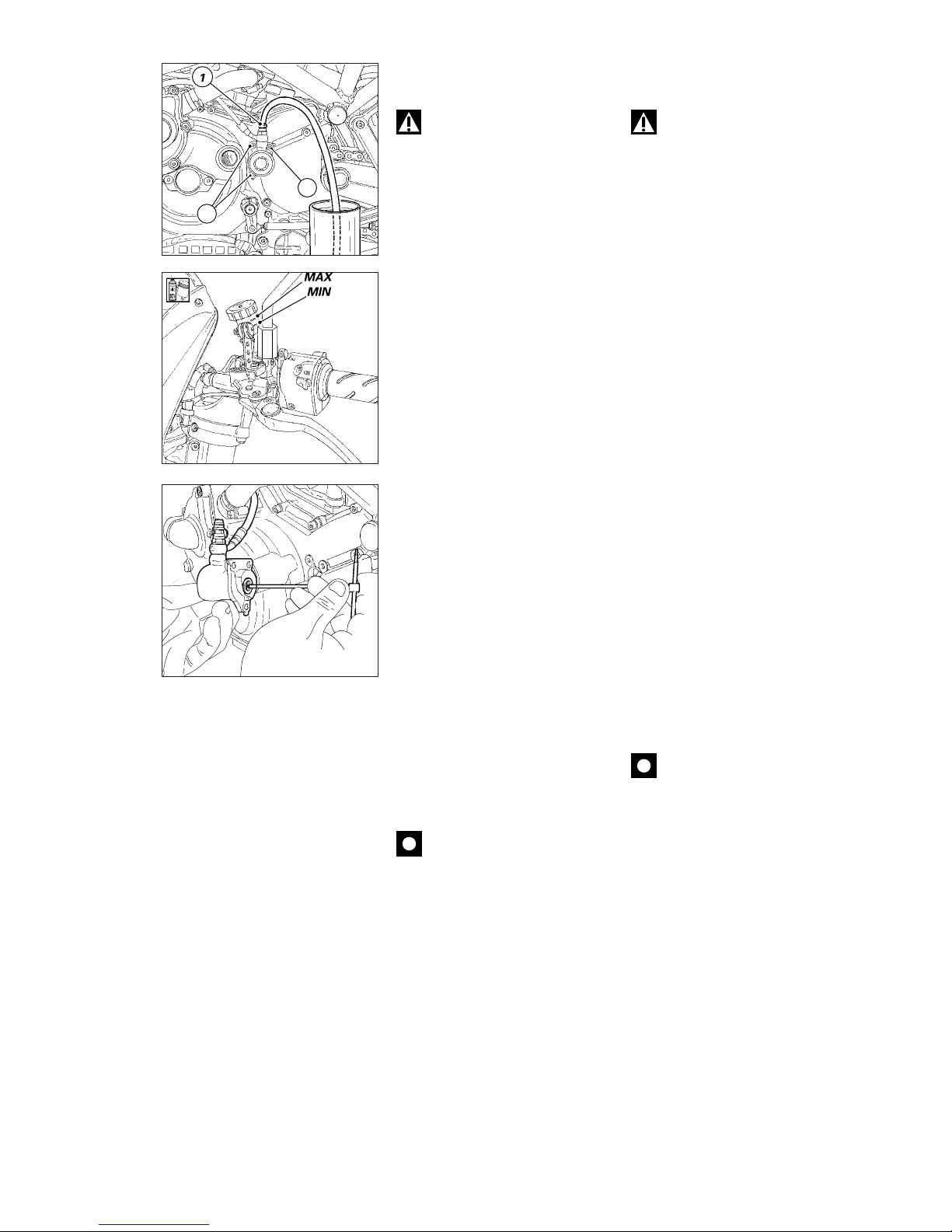
Manutenzione / Maintenance 47
CHANGING THE CLUTCH
FLUID
Warning
Corrosion and irritant hazard.
Clutch fluid is corrosive and will
damage paintwork. Avoid contact
with eyes and skin or injuries might
occur. In the event of accidental
contact, wash the affected part with
abundant running water.
Draining the circuit
❍
Remove the cover with
membrane from the fluid reservoir.
❍
Connect a common brake bleeder
(available on the market) to the
bleed cock (1) on the transmission
unit.
❍
Loosen the bleed cock and pump
with the bleeder until the fluid is
bled out of the circuit.
❍
If a bleeder is unavailable,
connect a piece of clear plastic
tubing to the bleed cock (1) on the
transmission unit. Place the other
end of the tube in a container on the
floor holding used clutch fluid.
❍
Unscrew the bleed cock by 1/4
turn.
❍
Operate the clutch control lever
until the fluid has been completely
bled out of the circuit. To empty the
circuit completely, remove the
transmission unit cap by
unscrewing the 3 screws (2).
❍
Use a wrench to push the piston
on the inside to drain all the fluid
inside the cap.
▲
Reassemble and follow
instructions given in "Removing the
sprocket cover and the clutch
transmission", under "Frame"
section.
Caution
During the next operation the
fluid level must remain topped up at
all times. The end of the transparent
plastic tubing must remain
immersed in the discharged fluid at
all times.
Filling the circuit
▲
Fill the reservoir with fluid from a
new container.
▲
Operate the clutch lever to fill the
circuit and bleed the air.
▲
Connect the bleeder to the bleed
cock.
▲
Pump the bleeder and loosen the
bleed cock. Make sure the level
does not go below MIN.
2
2
SOSTITUZIONE LIQUIDO
IMPIANTO FRIZIONE
Attenzione
Il liquido impiegato
nell’impianto frizione, oltre a
danneggiare la vernice, è
dannosissimo a contatto degli occhi
o della pelle; lavare quindi
abbondantemente con acqua
corrente la parte interessata in caso
di accidentale contatto.
Scarico circuito
❍
Togliere il coperchio con
membrana dal serbatoio liquido.
❍
Collegare alla valvola di spurgo (1)
del gruppo di rinvio uno spurgatore,
comunemente reperibile in
commercio.
❍
Allentare la valvola di spurgo e
pompare con lo spurgatore fino a
quando non esce più fluido
dall’impianto.
❍
In caso di indisponibilità dello
spurgatore, collegare alla valvola di
spurgo (1), un tubicino in plastica
trasparente e immergerne
l’estremità in un contenitore
appoggiato sul pavimento e
contenente liquido frizione usurato.
❍
Svitare di 1/4 di giro la valvola di
spurgo.
❍
Azionare la leva comando frizione
fino alla totale fuoriuscita del
liquido.
Per vuotare completamente il
circuito è consigliabile rimuovere il
cappellotto di rinvio svitando le tre
viti (2) di fissaggio.
❍
Spingere sul pistoncino interno
con una chiave per far fuoriuscire
tutto il liquido contenuto all’interno
del cappellotto.
▲
Procedere al rimontaggio
seguendo le indicazioni del
paragrafo “Smontaggio coperchio
pignone e rinvio frizione” nella
sezione “Mototelaio”.
Importante
Mantenere sempre a livello
l’olio dell’impianto durante tutta
l’operazione e lasciare l’estremità
del tubo trasparente sempre
immersa nel liquido scaricato.
Riempimento circuito
▲
Riempire il serbatoio con olio
prescritto prelevato da un
contenitore intatto.
▲
Azionare diverse volte la leva
frizione per riempire l’impianto e
spurgare l’aria.
▲
Collegare alla valvola di spurgo lo
spurgatore.
▲
Pompare con lo spurgatore e
allentare la valvola di spurgo
verificando sempre che il livello non
scenda al di sotto del MIN.
Page 48
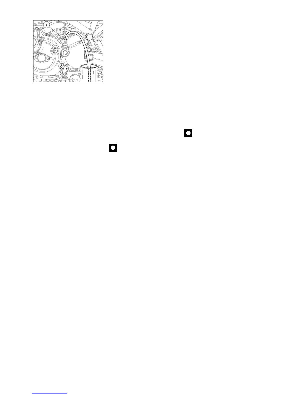
48 Manutenzione / Maintenance
▲
Ripetere quest’ultima fase fino a
quando, nel tubo trasparente
collegato alla valvola di spurgo, non
appaiono più bolle d’aria.
▲
Bloccare la valvola di spurgo alla
coppia prescritta e installare il
cappuccio di protezione.
▲
In caso di indisponibilità dello
spurgatore collegare alla valvola di
spurgo (1) un tubicino in plastica
trasparente come descritto per lo
scarico dell’impianto.
▲
Aprire la valvola di spurgo di 1/4
di giro e azionare la leva della
frizione fino a quando inizierà ad
uscire fluido dalla valvola di spurgo.
▲
Tirare completamente la leva e
poi allentare la valvola di spurgo di
almeno 1/4 di giro.
▲
Attendere qualche secondo;
rilasciare lentamente la leva e
chiudere contemporaneamente la
valvola di spurgo.
Importante
Non rilasciare la leva della
frizione se la valvola non è ben
serrata.
▲
Ripetere l’operazione finché dal
tubicino in plastica uscirà liquido
privo di bollicine d’aria.
▲
Bloccare alla coppia prescritta la
valvola di spurgo e installare il
cappuccio di protezione.
▲
Portare il liquido nel serbatoio 3
mm sopra al livello MIN.
▲
Rimontare la membrana e il
coperchio.
▲
Repeat this last procedure until
no air bubbles can be seen in the
transparent tubing connected to the
bleed cock.
▲
Tighten the bleed cock to the
specified torque and refit the cap.
▲
If a bleeder is unavailable,
connect a piece of clear plastic
tubing to the bleed cock (1) as
described for draining the circuit.
▲
Unscrew the bleed cock 1/4 of a
turn and operate the clutch lever
until fluid starts coming out of the
bleed cock.
▲
Pull the lever all the way and then
loosen the bleed cock at least 1/4 of
a turn.
▲
Wait a few seconds; release the
lever gradually while closing the
bleed cock.
Caution
Do not release the clutch
lever until the bleed cock has been
fully tightened.
▲
Repeat the bleeding operation
until air bubbles no longer come out
of the plastic tube.
▲
Tighten the bleed cocks to the
specified torque setting. Fit the cap
to the bleed cock.
▲
Top up the fluid in the reservoir, 3
mm over MIN level.
▲
Refit the membrane and the
cover.
Page 49

Registrazioni e regolazioni / Settings and adjustments 49
Registrazioni e regolazioni
Settings and adjustments
Page 50
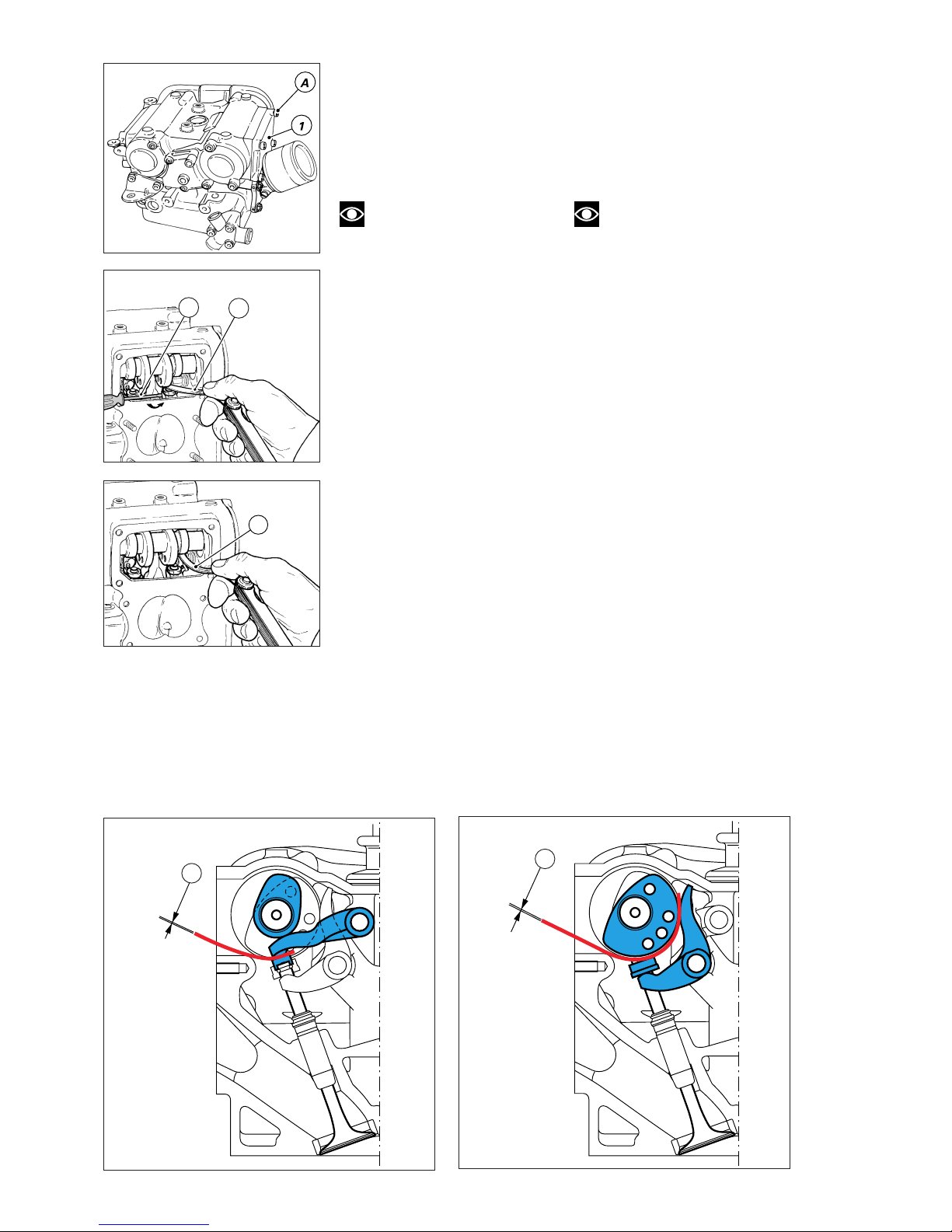
50 Registrazioni e regolazioni / Settings and adjustments
Sc
CONTROLLO GIOCO VALVOLE
Per poter eseguire le operazioni di
controllo e registrazione del gioco
valvole è necessario smontare tutti
quei componenti del motociclo che
possono ostacolare o impedire
l’operazione in corso.
Note
Per una miglior comprensione
le figure mostrano una testa
rimossa dal motore.
Per poter operare sulle valvole è
necessario rimuovere il serbatoio, la
scatola filtro e il corpo farfallato. Per
rimuovere i coperchi delle cinghie
della distribuzione è necessario
staccare la batteria e il porta batteria
lasciando tutti gli utilizzatori
collegati. Tutte queste operazioni
sono descritte al capitolo
"Operazioni generali". Le operazioni
raffigurate e le relative descrizioni di
questo paragrafo si riferiscono alla
testa verticale; il medesimo
procedimento dovrà essere
eseguito anche per la testa
orizzontale. Dopo aver rimosso il
coperchio di ispezione (1) agendo
sulle quattro viti (A), con uno
spessimetro verificare il gioco di
apertura (Sa). Con valvola in
posizione di riposo infilare la lama
dello spessimetro tra bilanciere
superiore e registro di apertura;
contemporaneamente fare leva con
un giravite (B) sotto alla forchetta del
bilanciere di chiusura.
Verificare poi il gioco tra bilanciere
inferiore e registro di chiusura (Sc).
Se i valori riscontrati risultano fuori
dai limiti indicati al capitolo
"Distribuzione" nella sezione
"Generalità", procedere alla
registrazione come descritto al
paragrafo successivo.
CHECKING VALVE
CLEARANCES
To check and adjust valve
clearances it will first be necessary
to remove all those components
which obstruct access to valve
components.
Note
For reasons of clarity, the
figures show the cylinder head
removed from the engine.
To reach the valves, remove the fuel
tank, the air box and the throttle
body first. To remove the timing
belt covers, disconnect the battery
and the battery holder leaving all
items connected. All these
operations are described under
section “General Operations”.
Procedures and figures contained in
this paragraph relate to the vertical
head; repeat the same procedures
on the horizontal head as well.
Undo the four screws (A) to remove
the inspection cover (1). Check
opening clearance (Sa) using a
feeler gauge.
With the valve in rest position, fit
the feeler gauge between upper
rocker arm and opening shim. At the
same time, lever with a screwdriver
(B) placed under the closing rocker
fork.
Then check closing clearance (Sc)
between lower rocker arm and
closing shim.
If the clearances measured are not
within the limits specified in
“Timing” under section
“Description”, adjust following the
instructions in the next paragraph.
Sc
Sa
Sa
B
Page 51
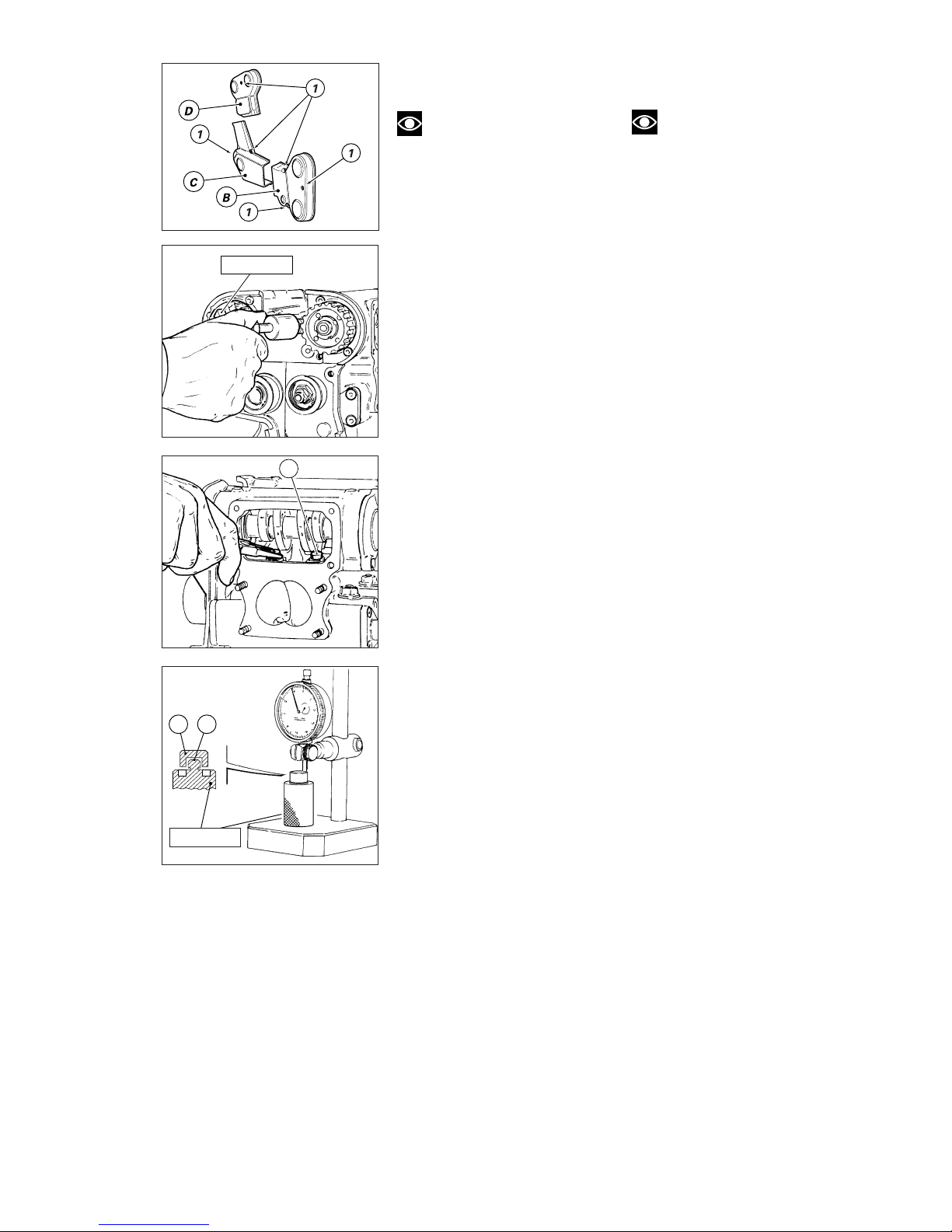
Registrazioni e regolazioni / Settings and adjustments 51
REGISTRAZIONE GIOCO
VALVOLE
Note
Tutte le operazioni di
smontaggio e rimontaggio dei
componenti delle teste, sono
descritte dettagliatamente alla
sezione "Motore".
❍
Rimuovere i coperchi (B), (C) e (D)
della distribuzione agendo sulle
relative viti (1).
Prima di procedere alla registrazione
del gioco tenere in considerazione
che, con distribuzione
desmodromica, quando il gioco di
apertura aumenta, diminuisce il
gioco di chiusura e viceversa.
Pertanto, in caso di sostituzione
del registro di apertura è
assolutamente necessario
sostituire anche quello
corrispondente di chiusura.
❍
Annotarsi, prima di procedere
nello smontaggio, i valori del gioco
rilevati per ogni singola valvola e
togliere la cinghia dell’albero di
distribuzione corrispondente.
Gioco di apertura
❍
Rimuovere il coperchio centrale
di tenuta dei perni bilancieri.
❍
Utilizzando l'attrezzo cod.
88713.1994 sfilare parzialmente il
perno del bilanciere superiore in
modo da poter spostare
lateralmente il bilanciere stesso
dall'interno della testa.
❍
Sfilare dalla sommità della valvola
il registro (2).
❍
Per sostituirlo con un altro di
spessore appropriato (scala da
1,8 a 5 mm), è necessario misurarne
lo spessore utilizzando un
comparatore o un calibro digitale.
❍
Azzerare lo strumento sulla
superficie di riferimento (3) ed
inserire il registro sulla spina
dell'attrezzo 88765.1298, quindi
effettuare la misurazione.
▲
Reinstallare il registro di spessore
adatto sulla valvola.
ADJUSTING VALVE
CLEARANCES
Note
All disassembly and
reassembly procedures relevant to
head components are outlined
under section “Engine”.
❍
Loosen screws (1) to take off the
timing covers (B), (C) and (D).
It should be remembered that on
desmodromic valve timing systems
any increase in opening clearances
will automatically decrease the
closing clearances and vice versa. If
you change the opening shim you
must therefore also change the
relevant closing shim.
❍
Before you remove any
components, note the clearance
values measured for each valve.
Remove the timing belt for the
corresponding camshaft.
Opening clearance
❍
Remove the central cover that
holds the rocker arm shafts.
❍
Fit tool part no. 88713.1994 and
partly slide out the shaft of upper
rocker arm. That way, the rocker arm
can be shifted to the side inside the
head.
❍
Remove the shim (2) from the
valve top.
❍
To select a replacement shim
with adequate thickness (1.8 to 5
mm range), measure the old shim
with a dial gauge or digital gauge.
❍
Set gauge to zero on the
reference surface (3) and place a
shim on top of the tool part no.
88765.1298 to measure its
thickness.
▲
Fit an adequate shim on the
valve.
88713.1994
2
2 3
88765.1298
Page 52
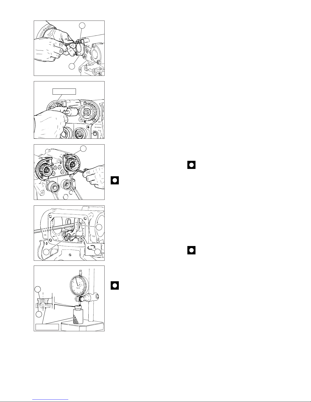
52 Registrazioni e regolazioni / Settings and adjustments
Gioco di chiusura
Se il gioco tra bilanciere inferiore e
scodellino risulta scarso o
abbondante è necessario, per poter
sostituire lo scodellino, rimuovere
l’albero a camme procedendo in
questo modo:
❍
Rimuovere il coperchietto (1)
svitando le viti (2).
❍
Sfilare completamente i perni dei
bilancieri superiori riutilizzando
l’attrezzo cod. 88713.1994.
❍
Svitare le due viti di fissaggio (3) e
sfilare il supporto completo di
puleggia e albero a camme dal lato
destro.
❍
Sfilare i bilancieri superiori
dall’interno della testa.
❍
Portare il pistone al P.M.S. per
evitare che la valvola, priva di ritegno,
cada all'interno del cilindro.
❍
Con la dovuta cautela, inserire un
perno di alluminio dall’apertura del
supporto albero a camme facendolo
passare dietro al pattino (A);
spingere quest’ultimo verso
l’esterno e, mantenendolo in questa
posizione, sfilare i due semianelli (4)
e lo scodellino di ritorno (5) dal
gambo della valvola.
Importante
È opportuno inserire uno
straccio sotto alle leve dei bilancieri
per evitare ai semianelli (4) di cadere
all’interno dei condotti di scolo olio.
❍
Controllare lo spessore dello
scodellino utilizzando un
comparatore o un calibro digitale.
❍
Azzerare lo strumento sulla
superficie di riferimento (B).
❍
Misurare l’altezza della spalla
dello scodellino (5).
▲
Scegliere lo scodellino
appropriato (vengono forniti con
spessore della spalla da 2,7 ÷3,7
mm) per ottenere il gioco prescritto
e rimontarlo rifacendo in modo
inverso le operazioni
precedentemente descritte.
Importante
Il montaggio di un registro di
spessore eccessivo porterebbe ad
una veloce usura dei bilancieri e
dell’albero a camme.
❍
Verificare nuovamente il gioco.
▲
Rimontare i componenti e le
strutture rimosse per l'operazione.
Closing clearance
If clearance between lower rocker
arm and closing shim is too small or
too large, remove the camshaft to
replace the closing shim. Proceed
as follows:
❍
Undo the screws (2) and remove
the cover (1).
❍
Remove the upper rocker arm
shafts using the tool part no.
88713.1994.
❍
Undo the two fastening screws
(3) and remove the support
complete with timing belt roller and
camshaft from the right side.
❍
Remove the upper rocker arms
from inside the head.
❍
Move the piston to the T.D.C.
(otherwise the loose valve would
fall into the cylinder).
❍
Gently fit an aluminum drift into
the opening of the camshaft
support and slide behind sliding
shoe (A). Push sliding shoe
outwards and keep it in this
position. Remove both split rings (4)
and the shim (5) from valve stem.
Caution
Put a cloth under the rockers
to prevent the split rings (4) from
falling into the oil scavenge holes.
❍
Check the shim thickness with a
dial gauge or a digital gauge.
❍
Set gauge to zero on the
reference surface (B).
❍
Measure the shim (5) shoulder
thickness.
▲
Select the right shim (shoulder
thickness available: 2.7 to 3.7 mm)
so to obtain the required clearance
and reverse the above procedure to
fit it.
Caution
Fitting a shim which is too
thick will cause rapid rocker arms
and camshaft wear.
❍
Check clearance again.
▲
Refit any components and parts
you have removed.
B
5
88765.1298
2
1
3
A
4
5
88713.1994
Page 53
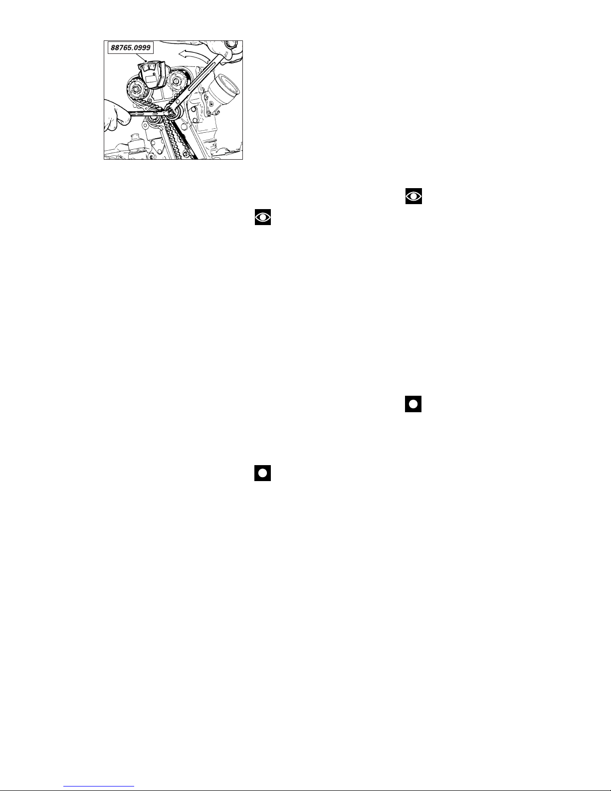
Registrazioni e regolazioni / Settings and adjustments 53
ADJUSTING TIMING BELT
TENSION
Timing belts can be tensioned up
with the engine in the frame. To
access the belts, remove the RH
fairing, the battery, the battery
mount and all components that
could interfere with the measuring
instrument and leave all items
connected (see section “Frame”).
❍
Unscrew the retaining screws on
the timing belt covers and remove
the covers.
Note
For reasons of clarity, the
figure shows the engine block
removed from the frame.
Set timing belt tension as follows:
❍
take cylinder to be tested to
combustion phase (valves closed);
❍
loosen the lock nut, turn the
eccentric and fully slacken the belt;
❍
fit the gauge part no.
88765.0999, properly adjusted for 4valve engines, to the portion of belt
between the two belt rollers that
drive the camshafts;
❍
turn the eccentric
counterclockwise until the
instrument pointer reads the max.
value; reverse direction of rotation
and fix tensioner at 2.5.
Caution
The tension value must be
read off on the gauge when the
tension is released (instrument
reading decreases).
▲
Tighten the lock nut to the
specified torque. Check that the
instrument reading is kept
unchanged.
▲
Refit any parts and components
you have removed.
REGISTRAZIONE TENSIONE
CINGHIE DISTRIBUZIONE
L'operazione di registrazione
tensione cinghie distribuzione è
possibile anche con motore
installato sul telaio, dopo aver
rimosso la semicarenatura destra, la
batteria, il porta batteria e tutti i
componenti che possono interferire
con lo strumento di misura,
lasciando tutti gli utilizzatori collegati
(vedi sezione “Mototelaio“).
❍
Rimuovere i coperchi esterni
delle cinghie distribuzione svitando
le viti di fissaggio.
Note
Per una migliore
comprensione, la figura mostra un
blocco motore rimosso dal telaio.
Per registrare la tensione agire nel
modo seguente:
❍
posizionare il cilindro relativo al
controllo in fase di scoppio (valvole
chiuse);
❍
allentare completamente la
cinghia agendo sull’eccentrico,
dopo aver allentato il dado di
serraggio;
❍
applicare lo strumento di misura
(cod. 88765.0999), opportunamente
configurato per motori 4 valvole, nel
braccio di cinghia compreso tra le
due pulegge di comando alberi
distribuzione;
❍
ruotare l’eccentrico in senso
antiorario raggiungendo il valore
max. sulla scala dello strumento;
invertendo il senso di rotazione,
fissare il tenditore al valore di 2,5.
Importante
Il valore della tensione deve
essere raggiunto durante la fase
passiva, quella del rilascio (valori
decrescenti sulla scala dello
strumento).
▲
Bloccare il dado di serraggio alla
coppia prescritta, controllando che
lo strumento mantenga il valore
impostato.
▲
Rimontare le strutture rimosse
per l'operazione.
Page 54
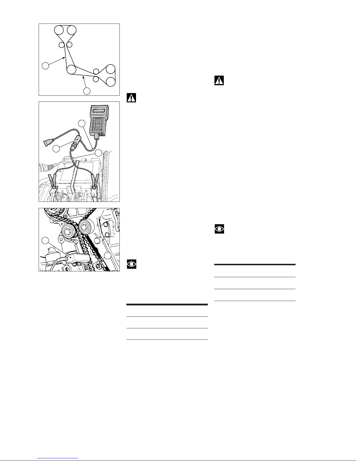
54 Registrazioni e regolazioni / Settings and adjustments
L’operazione di tensionamento
cinghie può essere effettuata
impiegando lo strumento di
diagnosi Mathesis, alla funzione
specifica.
●
L’operazione, effettuata con
l’aiuto del Mathesis, ha il vantaggio
di poter essere eseguita su
entrambe le cinghie con il motore
montato sul telaio.
Attenzione
Effettuare l’operazione sui
bracci delle cinghie (1) e (2) indicati
in figura.
▲
Collegare il cavo alimentazione
(3, cod. 514.1.034.1A) alla presa RC
586 (centrale) del Mathesis
utilizzando il cavo adattatore presa
batteria (6, cod. 514.1.038.1A) e
collegarlo alla presa A del cavo di
alimentazione e alla batteria della
moto.
▲
Collegare il cavo del lettore ottico
(4), dei dati di tensionamento, alla
porta COM1 del Mathesis.
▲
Fissare la staffa di supporto del
lettore ottico utilizzando la vite di
fissaggio del coperchio
copricinghia (5).
●
Direzionare il led verde centrale del
lettore ottico verso la parte centrale
del braccio della cinghia, posizionando
il lettore in asse rispetto alla cinghia ed
a una distanza di circa 1÷1,5 cm.
●
Sollecitare leggermente la cinghia
con un dito e leggere il valore sul
Mathesis.
Note
Il tempo che deve trascorrere
tra una lettura e l’altra deve essere
di almeno 1 sec.
Per i valori di tensionamento
controllare la tabella sotto riportata.
Cinghia Tensione (±5 Hz)
Orizzontale 110 Hz
Verticale 110 Hz
❍
Raggiunta la tensione desiderata,
serrare le viti di fissaggio del
tenditore mobile con l’attrezzo cod.
88713.1215 alla coppia prescritta.
●
Terminata l’operazione su un
cilindro, spostare il lettore sull’altro
cilindro e ripetere la procedura.
❍
Rimuovere il lettore ottico e gli
attrezzi per la fasatura.
▲
Procedere al rimontaggio dei
componenti del motore rimossi e
delle sovrastrutture.
1
2
4
5
3
A
6
Timing belts can be tensioned also
using the Mathesis tester, selecting
this special function.
●
The advantage coming from the
Mathesis tester is that both belts
can be tensioned without removing
engine from frame.
Warning
Carry out this operation on the
belt portions (1) and (2) shown in the
figure.
▲
Connect the power cable (3, part
No. 514.1.034.1A) to the Mathesis
tester RC586 (central) port with
battery adapter cable (6, part no.
514.1.038.1A) and then connect it
to power cable plug (A) and to the
bike battery.
▲
Connect the optical tension
reader cable (4) to the Mathesis
COM1 port.
▲
Secure the optical reader bracket
using the belt guard cover screw (5).
●
Aim the optical reader central
green led at the center of the belt
portion, taking care to align the
reader with the belt and keeping it
at a distance of about 1 – 1.5 cm.
●
Slightly flick the belt with your
fingers and note the reading on the
Mathesis tester.
Note
At least 1 second shall elapse
between one reading and the other.
For tensioning values, refer to the
table below.
Belt Tension (±5 Hz)
Horizontal 110 Hz
Vertical 110 Hz
❍
Once you have reached the
desired tension, tighten mobile
tensioner screws to the specified
torque using tool part No.
88713.1215.
●
Then move to the other cylinder
and repeat the above procedure
using the optical reader.
❍
Remove the optical reader, the
timing tools and the crankshaft
locking tool.
▲
Refit any engine parts and
outermost parts you have removed.
Page 55
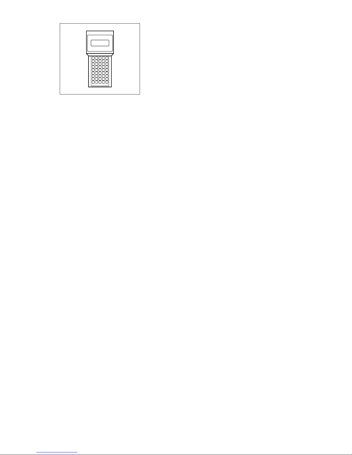
Registrazioni e regolazioni / Settings and adjustments 55
REGISTRAZIONE CORPO
FARFALLATO
Il corpo farfallato costituisce un
elemento molto importante per la
gestione della potenza del motore,
sia in termini di resa prestazionale
che nel controllo dell’emissione dei
gas di scarico.
Esso è composto da varie parti che
vengono assemblate e tarate
tenendo conto, in fase di
produzione, dei risultati acquisiti
dalle molteplici prove sostenute da
tecnici e collaudatori. Ogni elemento
del corpo farfallato costituisce parte
integrante e inscindibile del sistema
di iniezione-accensione e deve
funzionare in perfetta sintonia con
tutti gli altri elementi.
Per rispondere a questa esigenza di
equilibrio sconsigliamo di
intervenire in maniera parziale sul
corpo farfallato ed illustriamo la
procedura da seguire per la messa a
punto completa di questo elemento.
Illustreremo le seguenti operazioni:
❍
posizione del potenziometro;
❍
bilanciamento delle portate d’aria;
❍
registrazione titolo miscela al
regime di minimo.
La registrazione del titolo della
miscela al minimo è uno dei
parametri di funzionamento del
motore controllati da quasi tutte le
normative antinquinamento
internazionali. Il rispetto di questa
normativa porterà ad avere un titolo
della miscela “magro” (intorno al
valore 1,5% di CO) per contro,
l’esigenza di una migliore guidabilità
porterà invece ad un titolo di
“massimo carico” equivalente ad
una percentuale di CO compresa tra
3 e 6%. Considerando l’utilizzo in
molti casi agonistico del mezzo
teniamo conto di quest’ultimo
criterio.
Per l’esecuzione pratica di queste
operazioni è necessario disporre di:
❍
strumento di diagnosi
“MATHESIS” cod. 88765.1236 e
relativo manuale;
❍
vacuometro a colonne di mercurio;
❍
CO tester.
THROTTLE BODY
ADJUSTMENT
The throttle body is critical
component in engine power
management and is responsible for
performance and exhaust emission
control.
During production the throttle body
assembly is adjusted and set using
data from extensive testing. Each
part of the throttle body assembly is
an integral part of the injectionignition system and must work in
complete harmony with all the other
parts of the system.
The throttle body should therefore
be seen as a whole and we strongly
advise you to treat it as such. This
section describes the procedure for
adjusting the throttle body as a
system.
This section describes the following
operations:
❍
Positioning the throttle position
sensor
❍
Balancing the air flow
❍
Adjusting the idling mixture
The idling mixture strength is an
engine operating parameter subject
to strict international environmental
protection legislation. This
legislation tends towards a lean
mixture (with CO at 1.5%) while
optimum vehicle performance
tends towards full-load mixtures
with CO values between 3% and
6%.
As in many cases this motorcycle is
used for racing, the last value will be
considered.
For this operation you will require
the following instruments:
❍
“MATHESIS” tester, part no.
88765.1236 and relevant manual.
❍
Mercury column vacuometer.
❍
CO tester.
Page 56
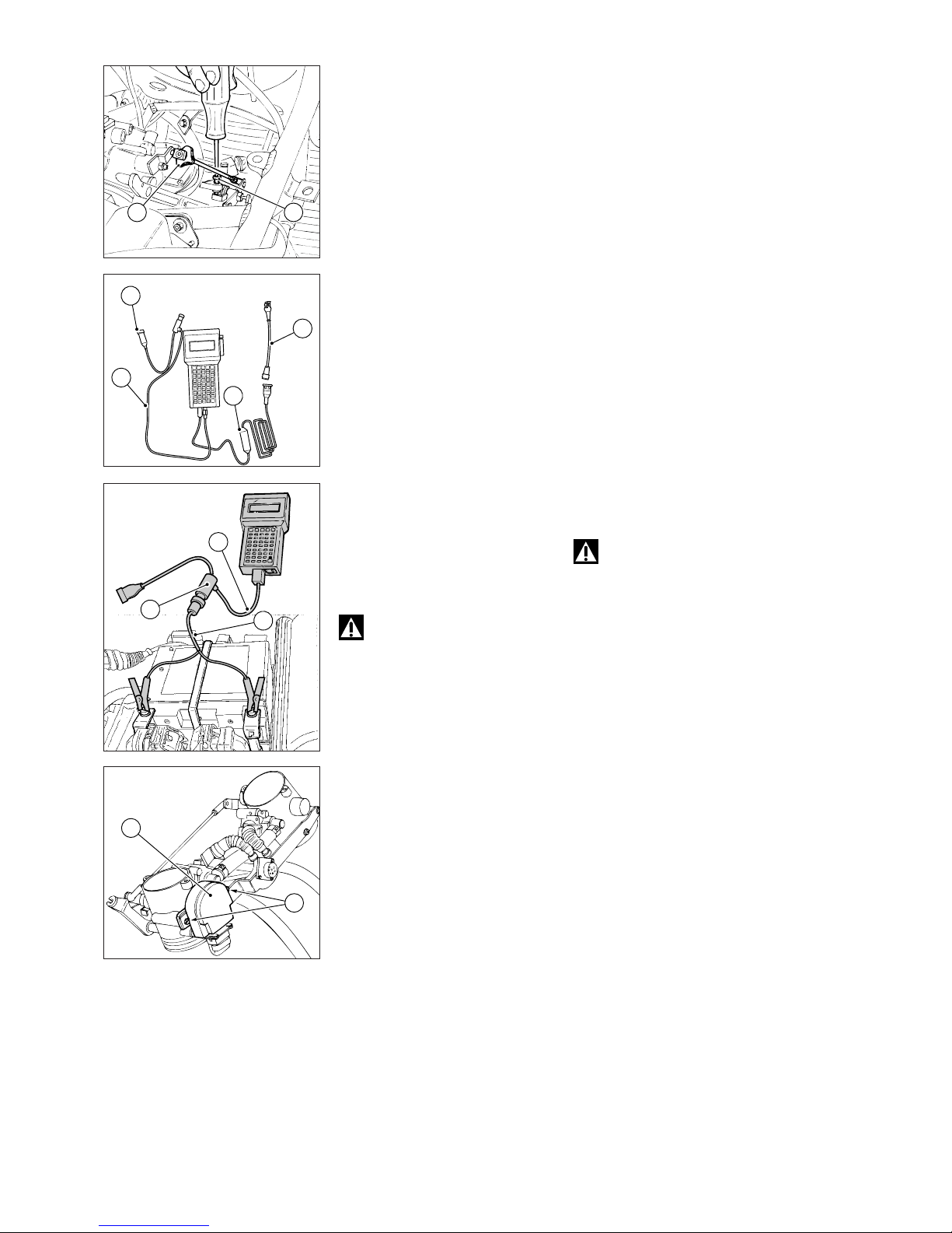
56 Registrazioni e regolazioni / Settings and adjustments
Posizione del potenziometro
Agire nel modo seguente dopo aver
portato a regime termico il motore:
❍
staccare il serbatoio dal telaio e
rimuovere l’air-box nel modo
descritto al capitolo “Smontaggio
scatola filtro aria” nella Sezione
"Mototelaio".
❍
Allentare completamente o
staccare il cavo di comando
acceleratore e dello starter dal
corpo farfallato per impedire che
uno dei due cavi non permetta la
chiusura della farfalla MASTER.
❍
Svitare la vite di registro (1) della
farfalla MASTER in modo che non
appoggi sul relativo finecorsa.
❍
Agire sul dado (2) del tirante di
collegamento delle farfalle per
accertarsi che la farfalla MASTER
(quella del lato potenziometro)
risulti completamente chiusa.
In alternativa è possibile controllare
se la farfalla del cilindro verticale è
completamente aperta.
▲
Collegare il cavo alimentazione
(3, cod. 514.1.034.1A) alla presa RC
586 (centrale) del Mathesis
utilizzando il cavo adattatore presa
batteria (8, cod. 514.1.038.1A) e
collegarlo alla presa A del cavo di
alimentazione e alla batteria della
moto.
❍
Disconnettere il potenziometro
dal cablaggio della moto.
Attenzione
Non collegare la presa di
diagnosi della moto al cavo di
alimentazione del Mathesis (presa A).
❍
Collegare il cavo (4, cod.
514.1.032.1A) per il collegamento
del potenziometro alla presa COM2
del Mathesis.
❍
Collegare al cavo (4) l’adattatore
(5, cod. 514.1.033.1A) e
quest’ultimo al potenziometro (6).
Registrazione del
potenziometro
❍
Introdurre la “Memory card”
nello strumento, entrare nella
funzione "Potenziometro" del menù
"Ausiliari". A questo punto si legge la
tensione in uscita del
potenziometro, con la farfalla
completamente chiusa. Il valore di
riferimento è 150 mV±15.
❍
In caso di valori differenti,
allentare le 2 viti (7) di fissaggio
potenziometro e, mantenendo in
posizione di chiusura la farfalla
MASTER, ruotare il potenziometro
fino a leggere il valore prescritto.
❍
Serrare le viti (7) del
potenziometro.
❍
Scollegare la connessione del
“MATHESIS” dal potenziometro e
riconnettere il cablaggio della moto.
Throttle sensor position
Warm up the engine and then
proceed as follows:
❍
Remove the fuel tank and the air
box as specified in “Removing the
air box”, under “Frame” section.
❍
Fully loosen or disconnect the
throttle and choke control cables
from the throttle body so that no
cable can interfere with MASTER
throttle closing.
❍
Unscrew the MASTER throttle
adjuster screw (1) so that it is not
resting on its end stop.
❍
Turn the nut (2) on the throttle
linkage rod to make sure that the
MASTER throttle (on the sensor
side) is fully closed. As an
alternative, it is possible to check if
the vertical cylinder throttle is fully
open.
▲
Connect Mathesis tester power
cable (3, part no. 514.1.034.1A) to
the Mathesis tester RC586 (central)
port with battery adapter cable (8,
part no. 514.1.038.1A) and then
connect it to power cable plug (A)
and to the bike battery.
❍
Disconnect throttle position
sensor from wiring harness.
Warning
Do not connect the bike
diagnosis port to the Mathesis
power cable (A port)
❍
Connect the throttle position
sensor cable (4, part No.
514.1.032.1A) to the Mathesis
COM2 port.
❍
Connect the adapter (5, part No.
514.1.033.1A) to cable (4) and then
connect the adapter to the throttle
position sensor (6).
Adjusting the throttle position
sensor
❍
Insert the “Memory card” into
the tester, access the “Throttle
position sensor” function into the
“Auxiliary” menu. The throttle
position sensor output voltage
value, with throttle fully closed, will
appear. The reference value is 150
mV±15.
❍
If the reading is outside the
specified limits, loosen the two
screws (7) on the throttle position
sensor. Keeping the MASTER
throttle closed, turn the throttle
position sensor until reading the
recommended value.
❍
Tighten throttle position sensor
screws (7).
❍
Disconnect the “MATHESIS”
tester from the throttle position
sensor and reconnect bike wiring.
2 1
5
A
4
3
7
6
3
A
8
Page 57
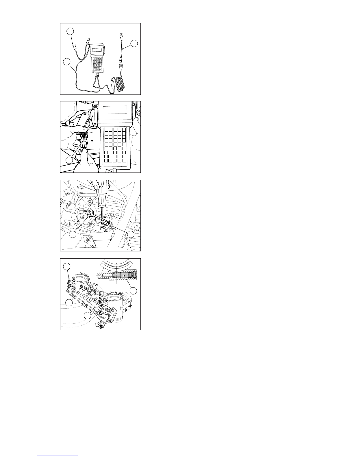
Registrazioni e regolazioni / Settings and adjustments 57
Registrazione titolo miscela al
regime minimo
❍
Collegare la presa (A) del cavo di
alimentazione (1) del Mathesis alla
presa diagnosi (2) posta sotto la
sella della moto.
Entrare nel menu “Autodiagnosi” e
selezionare il modello della moto.
Se tutto è andato regolarmente lo
strumento stabilisce il collegamento
con la centralina di controllo motore.
❍
Scegliere la funzione “Lettura
parametri”.
❍
Scegliere poi la funzione
“Controllo potenziometro farfalla”.
❍
Agire sulla vite di registro (3) della
farfalla MASTER in modo da ottenere
i valori di angolo farfalla e tensione:
2,3° equivalente a 403 mV.
▲
Se è stato scollegato, reinserire il
cavo di comando acceleratore nella
carrucola per attivare il comando e
registrare la corsa (vedi “Regolazione
cavi di comando acceleratore e
starter” di questa sezione).
❍
Agire sulla vite di registro (3) fino a
leggere i valori di angolo farfalla e
tensione ottenuti precedentemente.
Registrazione vite di fine
corsa della farfalla (cilindro
verticale)
❍
Disconnettere il potenziometro
dal cablaggio della moto e collegarlo
direttamente al Mathesis con il cavo
(4, cod. 514.1.032.1A) per il
collegamento del potenziometro .
❍
Entrare nella funzione “Ausiliari”,
poi “Potenziometro” e in seguito
“Registrazione potenziometro”.
❍
Prendere nota del valore rilevato.
❍
Agire lentamente sulla vite (5)
della farfalla del cilindro verticale in
modo da provocare una minima
variazione di tensione.
❍
Poi agire nuovamente sulla vite
(5) della farfalla del cilindro verticale
fino a rileggere sul Mathesis il
valore annotato.
Bilanciamento delle portare
d'aria
❍
Collegare il vacuometro ai
collettori aspirazione dopo aver
rimosso la vite che chiude il foro di
applicazione del raccordo dello
strumento.
❍
Chiudere completamente le viti
(6) di by-pass.
❍
Rimontare parte delle strutture
rimosse per poter avviare la moto e
mantenerla leggermente accelerata.
❍
Bilanciare la depressione nei
condotti di aspirazione agendo sul
dado (7) del tirante di collegamento
delle due farfalle.
Adjusting the idling mixture
❍
Connect the Mathesis tester
power cable (1) port (A) to the
diagnosis outlet (2) under the seat.
Enter the “Self-Diagnosis” menu
and select the bike model.
If the procedure has been carried
out successfully, the tester makes a
connection with the engine control
unit.
❍
Select the “Parameter Reading”
function.
❍
Select the “Throttle position
sensor check” function.
❍
Turn the adjuster (3) of the
MASTER throttle in order to reach
throttle and voltage values of 2.3°
equal to 403 mV.
▲
If the throttle control cable has
been removed, install it again into
the pulley in order to activate the
control and then adjust the travel
(refer to “Adjusting the throttle and
choke cables” under this section).
❍
Turn the adjuster (3) until reading
the throttle angle and voltage values
previously obtained.
Adjusting the throttle set
screw (vertical cylinder)
❍
Disconnect throttle position
sensor from bike wiring and
connect it directly to the Mathesis
tester using the throttle position
sensor adaptor cable (4, part No.
514.1.032.1A).
❍
Enter the “Auxiliary” function,
“Throttle position sensor” and then
“Throttle position sensor
adjustment”.
❍
Note the reading appearing on
the tester.
❍
Slowly turn the screw (5) of the
vertical cylinder throttle in order to
slightly change the voltage.
❍
Turn screw (5) of the vertical
cylinder throttle again until reading
the value you have noted on the
Mathesis tester.
Balancing the air flows
❍
Remove the screw on the
vacuometer connector hole and
connect the vacuometer to the
intake manifolds.
❍
Fully tighten and close the bypass screws (6).
❍
Refit those parts you have
removed, start the engine and run it
slightly fast.
❍
Balance the vacuum in the intake
manifolds by turning the nut (7) on
the throttle linkage rod.
4
A
1
2
7 3
5
6
6
6
Page 58
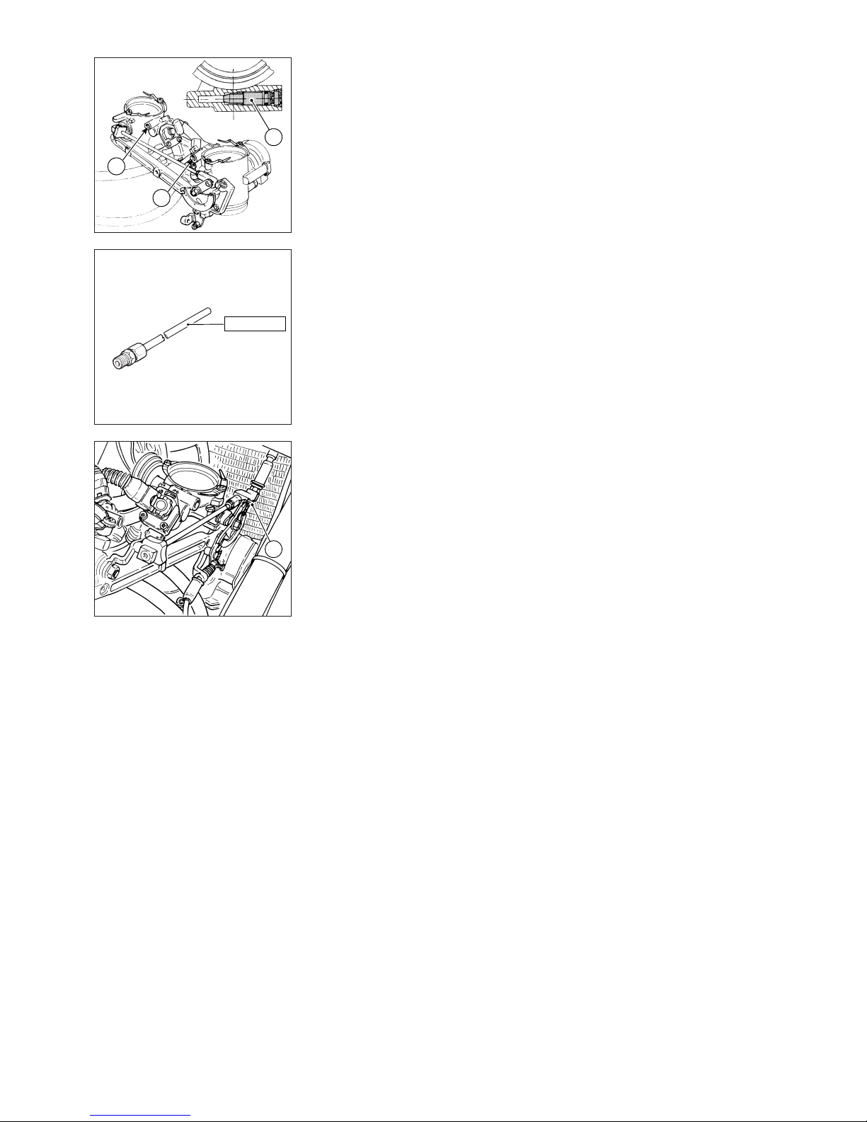
58 Registrazioni e regolazioni / Settings and adjustments
Registrazione del tenore di CO
❍
Allentare le viti (1) di by-pass di
ogni cilindro, fino ad ottenere un
regime minimo di circa 1 giro
(1000÷1100 min
-1
), con portate
d'aria bilanciate.
❍
Collegare il CO tester alle prese
sui tubi di scarico mediante i
raccordi cod. 88713.1010 per
leggere la composizione dei gas di
scarico.
❍
Verificare che la temperatura
motore superi i 65 °C.
❍
Effettuare le letture sul cilindro
orizzontale e sul cilindro verticale.
La differenza di contenuto di CO tra i
due cilindri non deve superare lo 0,5
% e comunque la percentuale di CO
deve essere ricompresa tra 3 e 6 %.
❍
Se la differenza di contenuto tra i
due cilindri è considerevole
(esempio 1%), agire singolarmente
sulle viti di by-pass (1) di ogni
cilindro per registrare il tenore di
CO: avvitare la vite di by-pass del
cilindro più “magro” oppure svitare
leggermente quella del cilindro più
“ricco”.
❍
Se la differenza tra i due cilindri
non è considerevole, quindi è
inferiore allo 0,5 %, ma la
percentuale di CO è inferiore a 3 %
o superiore al 6 %, agire sul trimmer
della centralina per registrare il CO
contemporaneamente sui due
cilindri.
❍
Per operare sul trimmer è
necessario utilizzare il Mathesis.
Entrare nella funzione
“Autodiagnosi”.
❍
Entrare in “Diagnosi attiva” e di
seguito in “Regolazione trimmer”.
Registrazione starter
❍
Azionare la leva di starter e,
operando sulla vite di registro (2) del
cavo comando starter, controllare
che il motore giri ad un regime di
1500/3000 min
-1.
▲
Per concludere la procedura di
registrazione del corpo farfallato
bloccare tutte le viti di regolazione
con riempitivo plastico in modo da
assicurare le regolazioni effettuate.
▲
Procedere al rimontaggio delle
strutture rimosse.
Adjusting the CO rate
❍
Loosen the by-pass screws (1) on
each cylinder of about one turn until
reaching an idling speed (1,000-
1,100 rpm) with balanced air flows.
❍
Connect the CO tester to the
outlets on the exhaust pipes with
unions part No. 88713.1010 to read
the exhaust gas composition.
❍
Make sure that engine
temperature is above 65 °C.
❍
Take readings on both horizontal
and vertical cylinders.
The CO rate difference between the
two cylinders should not exceed
0.5 % and the CO rate should
anyway be within 3 and 6%.
❍
If the difference between the two
cylinders is big – such as 1% - adjust
the CO rate turning the by-pass
screws (1) one at a time: screw the
by-pass screw of the “leaner”
cylinder or slightly loosen the screw
of the “richest” one.
❍
If the difference between the two
cylinders is small, i.e. below 0.5%
but the CO is lower than 3% or
above 6%, use the control unit
trimmer to adjust the CO rate on
both cylinders at the same time.
❍
To operate on the trimmer it is
necessary to use the Mathesis
tester.
Enter the "Self-diagnosis" function.
❍
Enter the “Active diagnosis”
function and then “Trimmer
adjustment”.
Adjusting the choke control
❍
Operate the choke lever and
check that the engine is running at
1,500/3,000 rpm turning the choke
control cable screw (2).
▲
Complete the throttle body
adjustment procedure by tightening
all the adjustment screws with
sealant in order not to modify the
adjustments made so far.
▲
Refit all removed parts.
1
1
1
88713.1010
2
Page 59
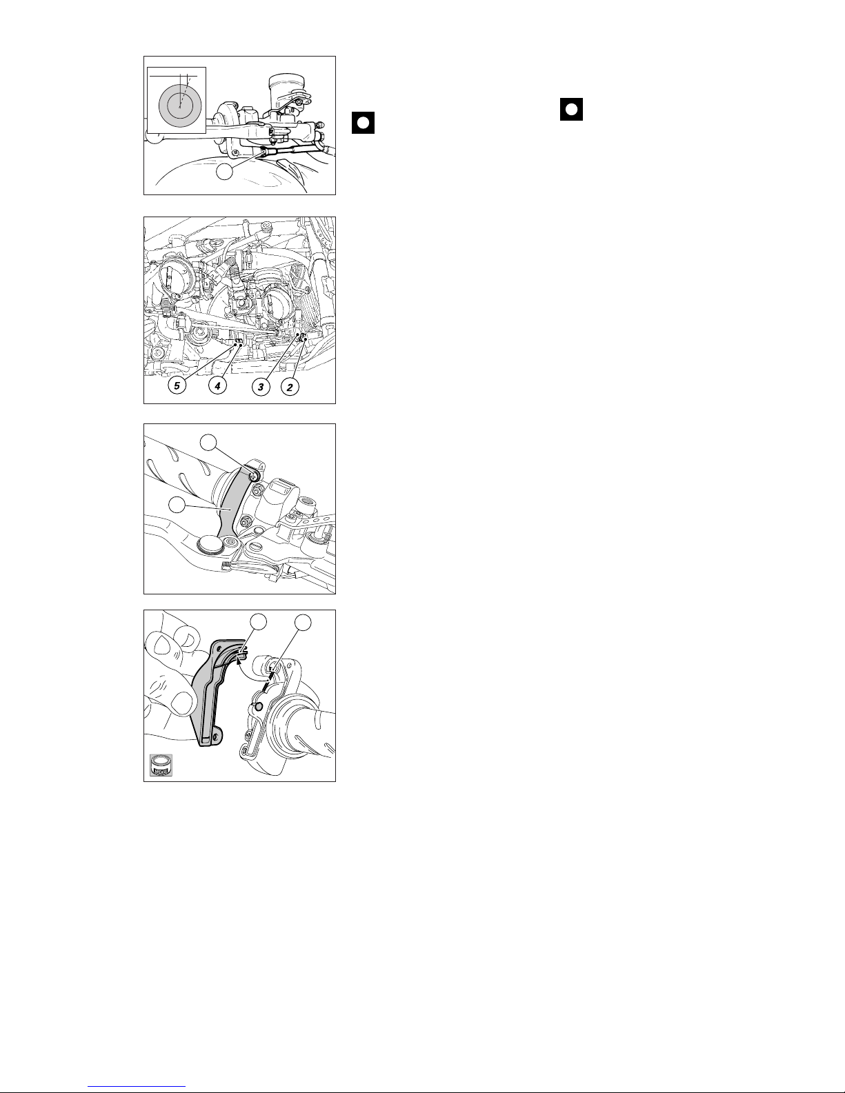
Registrazioni e regolazioni / Settings and adjustments 59
2÷4 mm
➤
➤
1
7
6
1
2
3
4
ADJUSTING THROTTLE AND
CHOKE CABLES
Caution
Adjustment of the throttle and
choke cables may affect the throttle
body adjustments. Before you
adjust these cables, read the above
paragraph.
The throttle twistgrip must have a
free travel of 2 to 4 mm (measured
on the twistgrip rim) in all steering
positions.
❍
Fine adjustment can be made by
turning the adjuster (1) on the
twistgrip.
For larger adjustments, use the
adjuster (2) located on the RH side
of the throttle body.
❍
Remove the cap, loosen the lock
nut (3) and turn the adjuster (2) to
obtain the required play.
▲
Tighten the lock nut and refit the
cap.
Turn the adjuster on the throttle
body to adjust the choke cable.
❍
Loosen the lock nut (5) and turn
the adjuster (4), as described above
for adjusting the throttle cable.
Check for proper conditions of outer
sheath of the throttle and choke
cables at regular intervals. Outer
plastic should not be damaged or
cracked.
❍
For smooth cable operation,
grease the cable ends with the
recommended grease at regular
intervals.
❍
Work the throttle or the choke to
make sure core cable is sliding
smoothly. If not so, change the
cable.
❍
To grease the throttle cable
mechanism: unscrew the 2 screws
(7) and remove the cover (6).
❍
Grease the cable end (8) and the
guide (A).
▲
Refit the cover with extreme
care. Insert the cable (8) in the guide
(A) in the cover (6).
▲
Tighten the two screws (7) to
secure the cover.
A
8
REGOLAZIONE CAVI DI
COMANDO ACCELERATORE E
STARTER
Importante
Operando sui cavi di comando
acceleratore e starter si può
compromettere la registrazione del
corpo farfallato. Consultare il
paragrafo precedente prima di
intervenire sui registri dei cavi
sopracitati.
La manopola di comando
dell’acceleratore in tutte le posizioni
di sterzata deve avere una corsa a
vuoto, misurata sulla periferia del
bordino della manopola, di 2÷4 mm.
❍
Se è necessario regolarla, agire
sull’apposito registro (1) situato in
corrispondenza del comando stesso.
Regolazioni più consistenti sul cavo
del gas si possono effettuare agendo
sul registro (2) posto sul lato destro
del corpo farfallato.
❍
Dopo aver sfilato il cappuccio,
allentare il controdado (3) e operare
sul registro (2) per stabilire il gioco
prescritto.
▲
Serrare il controdado e calzare il
cappuccio di protezione.
Per regolare il cavo dello starter è
necessario agire sull’unico registro
posto sul corpo farfallato.
❍
Agire analogamente a quanto
descritto per il cavo dell’acceleratore
operando sul registro (4) dopo aver
allentato il controdado (5).
Periodicamente è necessario
controllare la condizione delle guaine
esterne del cavo di comando
acceleratore e del cavo comando
starter. Non devono presentare
schiacciamenti o screpolature nella
copertura plastica esterna.
❍
Per mantenere la scorrevolezza dei
comandi lubrificare periodicamente
le estremità dei cavi di ogni
trasmissione flessibile con grasso
prescritto.
❍
Verificare, agendo sul comando, il
funzionamento scorrevole del cavo
interno: se si manifestano attriti o
impuntamenti sostituirlo.
❍
Per lubrificare il comando
trasmissione acceleratore è
necessario rimuovere il coperchietto
(6) svitando le 2 viti (7) di fissaggio.
❍
Ingrassare l’estremità del cavo (8)
e la slitta (A).
▲
Richiudere con molta attenzione
il comando inserendo il cavo (8)
nella slitta (A) del coperchio (6).
▲
Bloccare il coperchio con le due
viti (7) di fissaggio.
D
Page 60
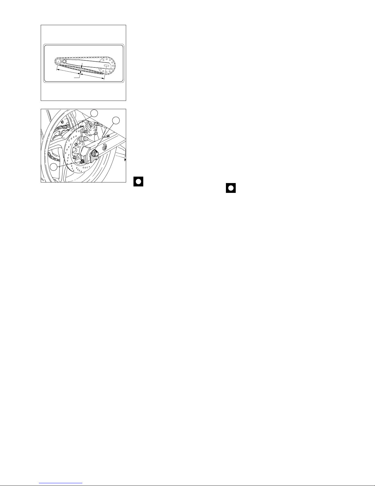
60 Registrazioni e regolazioni / Settings and adjustments
25 ÷ 27 mm
=
=
Tensionamento catena (sul cavalletto centrale)
Chain Tension adjustment (on the centre stand)
cod. 43312201A
1
2
3
REGOLAZIONE TENSIONE
CATENA
❍
Girare lentamente la ruota
posteriore per trovare la posizione in
cui la catena risulta più tesa.
❍
Spingere la catena con un dito
verso l’alto in corrispondenza della
mezzeria del forcellone (vedi
targhetta adesiva).
●
Il ramo inferiore della catena
deve poter compiere una
escursione di circa 25 ÷ 27 mm.
Per registrare la tensione procedere
come segue:
❍
Allentare il dado (1), del perno
ruota.
❍
Avvitare della stessa entità, in
senso orario, la vite (2) su entrambi i
lati del forcellone per aumentare la
tensione o svitare per diminuirla. In
quest’ultimo caso è necessario
spingere in avanti la ruota.
Importante
Una catena non correttamente
tesa è causa di una veloce usura
degli organi di trasmissione.
❍
Verificare la corrispondenza, su
entrambi i lati del forcellone, delle
tacche di posizionamento; in questo
modo sarà garantito il perfetto
allineamento della ruota.
▲
Bloccare i dadi (1) del perno ruota
alla coppia prescritta.
▲
Bloccare le viti (2) di registro
tensione alla coppia prescritta.
Verificare inoltre il serraggio dei dadi
di fissaggio (3) della corona alla
flangia. Questa operazione è
possibile anche con ruota montata,
introducendo dal lato opposto una
chiave a brugola snodata di 8 mm
per mantenere fermi i perni in
corrispondenza dei dadi sopracitati.
ADJUSTING CHAIN TENSION
❍
Move the motorcycle rear wheel
slowly until finding the position
where chain is tightest.
❍
At mid-length of the swingarm
(see adhesive label on swingarm),
press the chain upwards with one
finger and measure the amount of
slack.
●
The lower section of chain must
give by about 25 - 27 mm when
pressed at the point indicated.
To tension the chain:
❍
Loosen the nut (1) of the wheel
shaft.
❍
To tighten chain tension, tighten
(clockwise) the adjuster screw (2) on
both sides of the swingarm by equal
amounts. To loosen the chain
tension, unscrew the adjuster
screw. Push the wheel forward
when slackening the chain.
Caution
Incorrect chain tension can
cause rapid wear of transmission
components.
❍
Check that the wheel is properly
aligned by checking that the
notches of both sides of the
swingarm are properly positioned.
▲
Tighten the nuts (1) on the wheel
shaft to the specified torque.
▲
Tighten the adjusters (2) to the
specified torque.
Check for proper tightening of the
nuts (3) fixing the rear sprocket to
the wheel flange. To do this with
the wheel mounted on the bike,
lock the bolts on the other side in
position with an 8 mm jointed
socket spanner while you tighten
the nuts.
Page 61
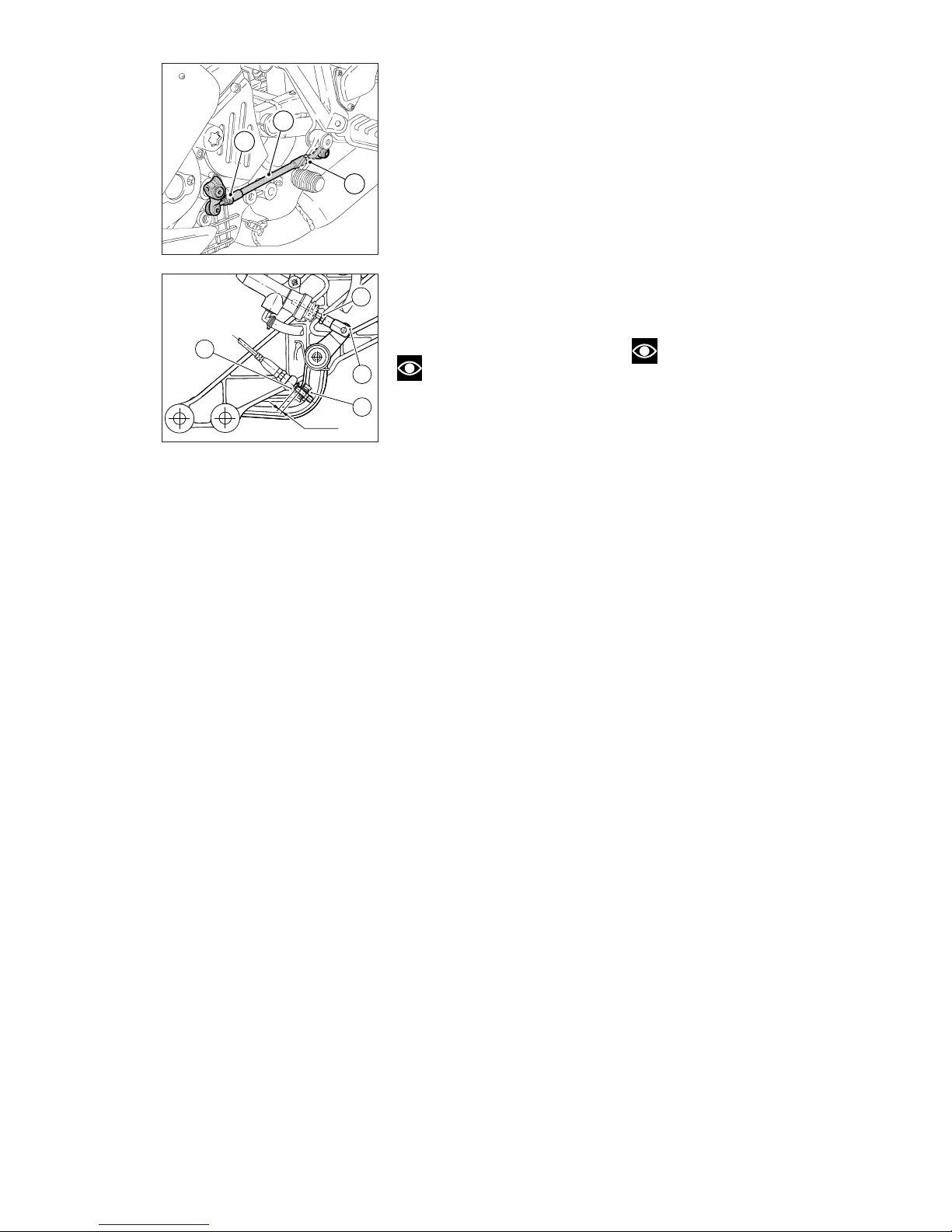
Registrazioni e regolazioni / Settings and adjustments 61
A
C
B
REGISTRAZIONE POSIZIONE
PEDALE COMANDO CAMBIO
E FRENO POSTERIORE
Per assecondare le esigenze di
guida di ogni pilota è possibile
modificare la posizione delle leve
comando cambio e freno posteriore
rispetto all’appoggiapiedi.
Le figure riportano le quote per
ristabilire la configurazione originale
di detti comandi.
Per modificare la posizione della
leva comando cambio agire nel
modo seguente:
❍
Bloccare l’asta (A) e allentare i
controdadi (B) e (C).
Note
Il dado (B) ha un filetto
sinistrorso.
❍
Ruotare l’asta (A) facendo
assumere al pedale cambio la
posizione desiderata.
▲
Serrare contro l’asta entrambi i
controdadi.
Per modificare la posizione della
leva comando freno posteriore agire
nel modo seguente:
❍
Allentare il controdado (D).
❍
Ruotare la vite (E) di registro corsa
pedale fino a stabilire la posizione
desiderata.
▲
Serrare il controdado (D).
●
Verificare, agendo a mano sul
pedale, che questo presenti un
gioco di circa 1,5÷2 mm prima di
iniziare l’azione frenante.
Se così non risulta occorre
modificare la lunghezza dell’astina di
comando della pompa nel modo
seguente:
❍
Allentare il controdado (F)
sull’astina della pompa.
▲
Avvitare l’astina sulla forcella (G)
per aumentare il gioco o svitarla per
diminuirlo.
▲
Serrare il controdado (F) e
verificare nuovamente il gioco.
ADJUSTING THE POSITION
OF THE GEAR CHANGE AND
REAR BRAKE PEDALS
The position of the gear change and
rear brake pedals in relation to the
footpegs can be adjusted to suit
rider preferred riding position.
When you want to restore the
original configuration, refer to the
dimensions given in the figures at
the side.
To adjust the position of the gear
change pedal, proceed as follows:
❍
Clamp the rod (A) and loosen the
lock nuts (B) and (C).
Note
Lock nut (B) has a left-hand
thread.
❍
Turn the rod (A) until the gear
change pedal is in the position
required.
▲
Tighten the two lock nuts onto
the rod.
To adjust the position of the rear
brake pedal, proceed as follows:
❍
Loosen the lock nut (D).
❍
Turn the pedal travel adjuster
screw (E) until the pedal is in the
position required.
▲
Tighten the lock nut (D).
●
Operate the pedal by hand and
check that there is 1.5 to 2 mm of
free pedal travel before the brake
begins to operate.
If this is not the case, adjust the
length of the brake cylinder control
rod as follows:
❍
Loosen the lock nut (F) on the
brake cylinder control rod.
▲
To increase the amount of pedal
free travel, screw the rod further
into the fork (G). Unscrew the rod to
decrease.
▲
Tighten the lock nut (F) and check
the amount of pedal free travel.
F
G
D
8 mm
E
Page 62
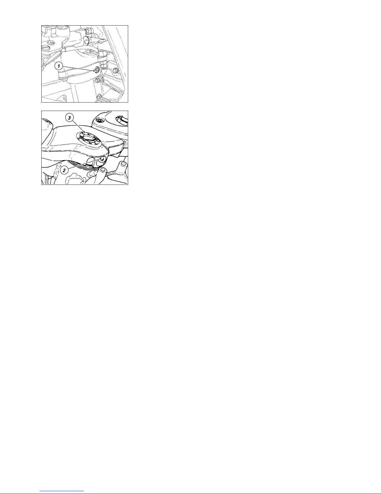
62 Registrazioni e regolazioni / Settings and adjustments
REGISTRAZIONE GIOCO
CUSCINETTI DELLO STERZO
Riscontrando eccessiva libertà di
movimento dei semimanubri o
scuotimento della forcella rispetto
all’asse di sterzo è necessario
procedere alla regolazione nel modo
seguente:
❍
Allentare le viti (1) sulla testa di
sterzo in corrispondenza dei
morsetti di tenuta steli forcella.
❍
Allentare la vite (2) del morsetto
di tenuta cannotto sulla testa di
sterzo.
❍
Ruotare con l’apposito attrezzo
cod. 88713.1058 la ghiera (3) di
registrazione fino alla coppia
prescritta.
▲
Serrare tutte le viti allentate in
precedenza alla coppia di serraggio
prescritta.
ADJUSTING STEERING HEAD
BEARING PLAY
Excessive handlebar play or shaking
forks in the headstock indicate that
the play in the steering head
bearings requires adjustment.
Proceed as follows:
❍
Loosen the top screws (1) on the
steering head at the fork leg clamps.
❍
Loosen the clamping bolt (2) that
holds steering tube to steering
head.
❍
Tighten the ring nut (3) to the
specified torque using the tool part
no. 88713.1058.
▲
Tighten all the previously
loosened screws to the specified
torque.
Page 63
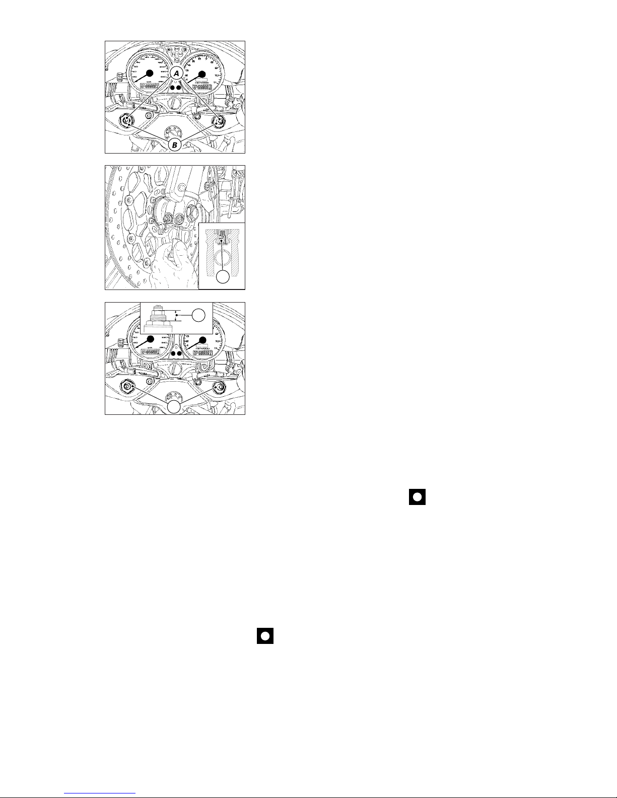
Registrazioni e regolazioni / Settings and adjustments 63
C
REGOLAZIONE FORCELLA
ANTERIORE
La forcella è regolabile sia nella fase
di estensione sia nella
compressione degli steli.
La regolazione avviene per mezzo
dei registri esterni a vite:
A) per modificare il freno idraulico in
estensione;
B) per modificare il precarico delle
molle interne;
C) per modificare il freno idraulico in
compressione.
❍
Ruotare con un piccolo cacciavite
a taglio il registro (A), posto sulla
sommità di ogni stelo forcella, per
intervenire sul freno idraulico in
estensione.
❍
Per agire sul registro (B)
introdurre un cacciavite attraverso il
foro passante sul perno ruota in
corrispondenza dell’asse stelo
forcella.
Ruotando le viti (A e B) di
regolazione si avvertiranno degli
scatti, ognuno dei quali corrisponde
ad una posizione di smorzamento.
Avvitando completamente la vite
fino a bloccarla si ottiene la
posizione “0”, che corrisponde alla
massima frenatura.
A partire da questa posizione,
ruotando in senso antiorario, si
possono contare i vari scatti che
corrisponderanno successivamente
alle posizioni 1, 2, ecc.
Le posizioni standard sono le
seguenti:
●
compressione:
12 scatti;
●
estensione:
11 scatti.
Il valore massimo è di 14 scatti (per
l’estensione e la compressione) a
cui corrisponde la posizione di
minima frenatura.
❍
Per modificare il precarico della
molla interna ad ogni stelo ruotare il
registro ad estremità esagonale (C)
con una chiave esagonale di 22 mm.
Il valore del precarico (1) può variare
tra 25 e 10 mm.
●
La taratura originale corrisponde a
16 mm.
Importante
Regolate i registri di entrambi
gli steli sulle medesime posizioni.
ADJUSTING THE FRONT FORK
Front fork features both
compression and rebound damping
adjustment.
The fork has three external
adjusters for:
A) rebound damping;
B) inner spring preload;
C) compression damping.
❍
To set rebound damping, turn the
top adjuster (A) on each fork leg
with a small flat screwdriver.
❍
Insert a screwdriver through the
wheel shaft hole at the fork leg axis
and turn the adjuster (B).
Adjusters (A and B) have click
settings corresponding to different
damping positions.
Hardest damping is obtained with
the adjuster fully tightened to the
“0” position.
Start with this position and turn
counterclockwise. You can count all
screw clicks which correspond to
position 1, 2 and so on.
Standard settings:
●
compression
12 clicks
●
rebound
11 clicks
Rebound and compression
adjusters have a total of 14 clicks
each; this setting corresponds to
softest damping.
❍
To change the spring pre-load for
each fork leg, turn the hex. adjuster
(C) with a 22 mm wrench. Spring
pre-load (1) varies between 25 and
10 mm.
●
Factory preload setting is 16 mm.
Caution
Adjusters of both fork legs
must be set to the same position.
B
1
Page 64
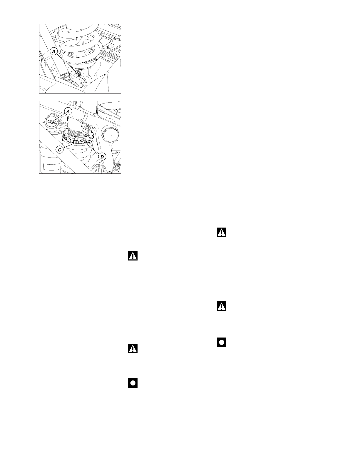
64 Registrazioni e regolazioni / Settings and adjustments
REGOLAZIONE
AMMORTIZZATORE
POSTERIORE
L’ammortizzatore posteriore è
dotato di registri esterni che
permettono di adeguare l’assetto
della moto alle condizioni di carico.
Il registro (A), in corrispondenza del
fissaggio inferiore
dell’ammortizzatore al forcellone,
regola il freno idraulico nella fase di
estensione (ritorno).
Il registro (B), solidale al polmone di
espansione dell’ammortizzatore sul
lato sinistro, regola il freno idraulico
nella fase di compressione.
Le ghiere (C) e (D), poste nella parte
superiore dell’ammortizzatore,
registrano il precarico della molla
esterna.
Ruotando in senso orario i registri
(A) e (B) si aumenta il freno;
viceversa diminuisce.
●
Taratura Standard:
dalla posizione di tutto chiuso di:
registro A 19 click
registro B 2 giri
Per modificare il precarico della
molla allentare, con una chiave a
settore, la ghiera superiore (C).
Avvitando o svitando la ghiera
inferiore (D) aumenterà o diminuirà
il precarico.
●
Lunghezza Standard della molla:
153 ± 1,5 mm
Attenzione
Per ruotare le ghiere di
registrazione del precarico utilizzare
solamente una chiave specifica ed
usarla con particolare cautela per
evitare che il dente della chiave
possa uscire improvvisamente dal
vano della ghiera durante il
movimento. Se ciò dovesse
accadere, la mano dell’utilizzatore
potrebbe urtare violentemente altre
parti del motociclo. Non utilizzare
assolutamente chiavi con dente
troppo piccolo o con impugnatura
troppo corta.
Attenzione
L’ammortizzatore contiene
gas ad alta pressione e potrebbe
causare seri danni se smontato da
personale inesperto.
Importante
Nell’uso con passeggero e
bagaglio precaricare al massimo la
molla dell’ammortizzatore
posteriore per migliorare il
comportamento dinamico del
veicolo ed evitare possibili
interferenze col suolo. Ciò può
richiedere l’adeguamento della
regolazione del freno idraulico in
estensione.
ADJUSTING THE REAR
SHOCK ABSORBER
The rear shock absorber has outer
adjusters for setting motorcycle so
as to match load conditions.
The adjuster (A) is at the monoshock
bottom end, at the connection with
the swingarm. This adjuster sets
rebound damping.
The adjuster (B) is integral with the
expansion chamber on the LH side
of the shock absorber. This adjuster
sets compression damping.
Ring nuts (C) and (D) on top of the
shock absorber, adjust the external
spring pre-load.
Turn the adjusters (A) and (B)
clockwise to increase damping; turn
the adjusters counterclockwise to
obtain softer damping.
●
Standard setting:
from the fully closed position:
A adjuster: 19 clicks
B adjuster: 2 turns.
To change the spring pre-load,
loosen the upper ring nut (C) with a
pin wrench. To increase or decrease
the spring pre-load, tighten or
loosen lower ring nut (D).
●
Standard spring length:
153 ± 1.5 mm
Warning
Use a special wrench only to
turn the ring nuts for pre-load
adjustment. When applying
pressure to the wrench, ensure that
wrench pins do not slip out
suddenly from the slots in the ring
nut. This could cause minor injuries
to your hands. Do not use wrenches
which are too small or have short
handles.
Warning
The shock absorber is filled
with high-pressure gas and could
cause damage if inexpertly
dismantled.
Caution
If the motorcycle is to be
driven with a pillion rider and
luggage on board, we recommend
that you set the rear shock absorber
spring pre-loading to the maximum
to ensure the best handling and
proper ground clearance at all times.
It may also be necessary to adjust
rebound damping accordingly.
Page 65

Mototelaio / Frame 65
Mototelaio
Frame
Page 66
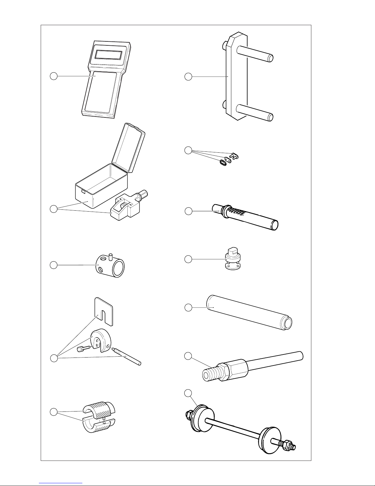
66 Mototelaio / Frame
5
4
2
10
9
3
6
11
12
7
8
1
Page 67

Mototelaio / Frame 67
Attrezzi speciali per interventi sul mototelaio/Special service tools for frame
Rif./Ref. n. codice/part no. denominazione description
1 88713.1236 Strumento di diagnosi
88713.1237 Strumento di diagnosi
88713.1239 Strumento di diagnosi
88713.1238 Strumento di diagnosi
88713.1240 Strumento di diagnosi
2 88713.1344 Attrezzo montaggio catena
3 0000.70139 Chiave perno ruota anteriore
4 88713.0957 Attrezzo di ritegno distanziale
per forcella SHOWA
5 88713.0960 Attrezzo per revisione forcelle
SHOWA - montaggio anello di
tenuta
6 88713.1515 Supporto telaio/motore
7 677.4.003.1A Giunto
8 88713.1071 Tampone montaggio cuscinetti a
rullini del bilanciere
9 88713.1058 Chiave montaggio tappo
cannotto di sterzo
10 88713.1072 Tampone piantaggio
semicuscinetto base di sterzo
11 88713.1010 Raccordo prelievo gas di scarico
12 88713.1062 Attrezzo montaggio cuscinetti del
cannotto di sterzo
Tester
Tester
Tester
Tester
Tester
Tool to install chain
Wrench for front wheel shaft
Tool to hold SHOWA fork spacer
Tool to overhaul SHOWA forks install oil seal
Engine/frame support
Joint
Drift to install the rocker needle
bearings
Wrench to install the steering
tube cap
Drift to drive half bearing into
the bottom yoke
Exhaust gas pick-up point
Tool to install the steering tube
bearings
Page 68
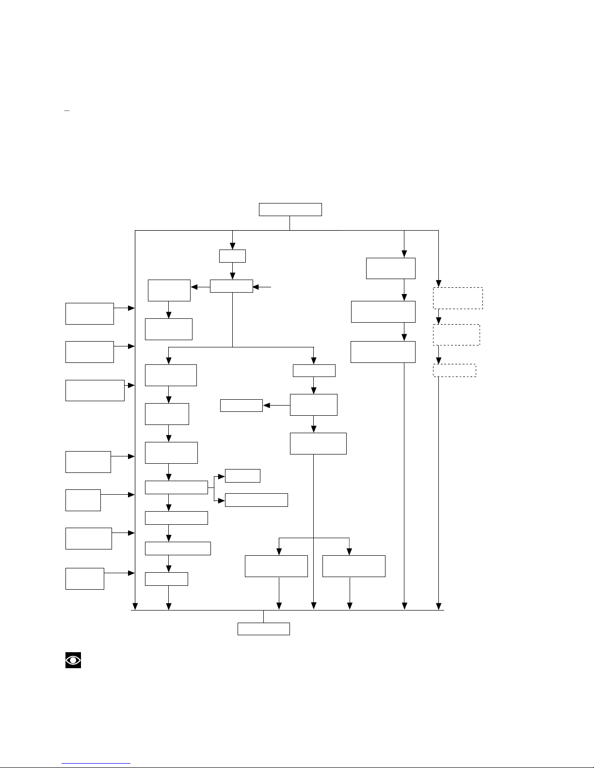
68 Mototelaio / Frame
MOTOCICLO
Vite fix. post.
Motore/Telaio
Leva rinvio
cambio
Supporto
freno post.
Perno
forcellone
Rinvio
frizione
Coperchio
pignone
Pignone
motore
Sella
(*)
SerbatoioFlangia
serbatoio
Ind. livello
carburante
Cop. scatola
filtro aria
Cartuccia
filtro aria
Scatola filtro
aria
Corpo farfallato
Iniettori
Potenziometro
Collettore T.V.
Vaso esp. acqua
Radiatore
Batteria
Centralina
Supporto
batteria
Viti fissaggio
motore/telaio
Dist. impianto
raffreddamento
Colleg. elettrici
motore
MOTORE
Tubo di scarico
testa vert.
Tubo di scarico
testa orizz.
Cupolino
Specchi
retrovisori
Specchi
retrovisori
Silenziatori
di scarico
SCHEMA SEQUENZA DI SMONTAGGIO COMPONENTI MOTOCICLO
Questo schema serve di aiuto per lo smontaggio dei componenti del motociclo. È finalizzato alla rimozione
completa del motore dal telaio ma visualizza anche procedure parziali. Individuare il componente da smontare e
seguire le frecce per conoscere le parti da rimuovere.
*) È sufficiente sollevarlo.
Operazioni non necessarie alla rimozione del motore
Note
Per il rimontaggio dei componenti del motociclo è necessario eseguire con ordine inverso quanto descritto
per lo smontaggio. Annotazioni particolari riguardanti il rimontaggio verranno segnalate all’inizio del testo con un
triangolo “
▲
”.
Page 69
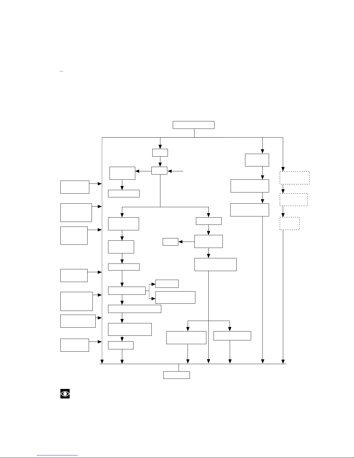
Mototelaio / Frame 69
MOTORCYCLE
Engine-toframe rear
screw
Gearbox
transmission
lever
Rear brake
mount
Swingarm
shafi
Clutch
transmission
unit
Front sprocket
cover
Engine
sprocket
Seat
(*)
TankTank
flange
Fuel sensor
Air filter box
cover
Air filter
cartridge
Air filter box
Throttle body
Injectors
Throttle position
sensor
Vertical head manifold
Coolant expansion
reservoir
Radiator
Battery
CPU
Battery
mount
Engine-to-frame
fastening screws
Cooling systemEngine electrical
connections
ENGINE
Vertical head
exhaust pipe
Horizontal head
exhaust pipe
Headl.
fair.
Rear-view
mirrors
Rear-view
mirrors
Exhaust
silencer
MOTORCYCLE COMPONENT DISASSEMBLY SEQUENCE
This diagram is a guide to the sequence to be followed when dismantling motorcycle components. The diagram is
designed to show the sequence to be followed for removing the engine from the frame; it also shows partial
sequences for other components. Select the component you wish to remove and then follow the arrows to see
which other parts that will have to be disassembled.
(*) Raise only.
Operations not necessary for complete engine removal.
Note
To reassemble the motorcycle components, follow the disassembly sequence in reverse order. Special
instructions regarding reassembly are marked with a “
▲
” triangle.
Page 70
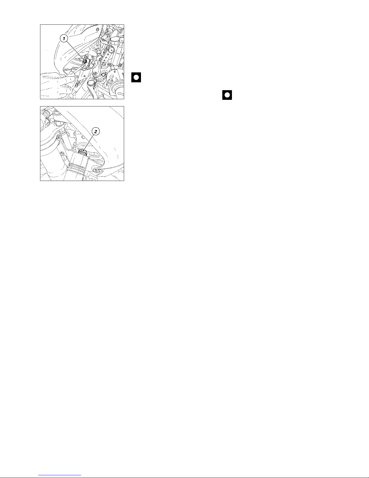
70 Mototelaio / Frame
REMOVING THE HEADLIGHT
FAIRING
❍
Unscrew the two fastening
screws (1).
❍
Remove the screws (1) and keep
the nylon washers placed between
screw and headlight fairing.
❍
Pull the headlight fairing out the
two seals (2).
Caution
At reassembly, make fairing
slots match with relevant seals.
SMONTAGGIO CUPOLINO
❍
Svitare le due viti di serraggio (1).
❍
Rimuovere le viti (1) facendo
attenzione a non perdere le rosette
in nylon poste tra vite e cupolino.
❍
Sfilare il cupolino dai 2 gommini (2).
Importante
Durante il rimontaggio
posizionare le asole sul cupolino in
corrispondenza dei rispettivi
gommini.
Page 71
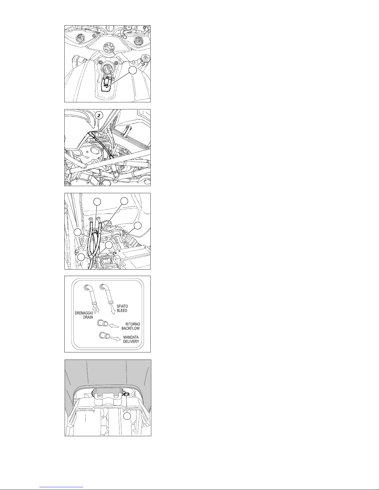
Mototelaio / Frame 71
D
3
M
R
S
4
1
5
SMONTAGGIO SERBATOIO
❍
Sganciare la leva (1) di ancoraggio
anteriore del serbatoio.
❍
Sollevare il serbatoio utilizzando
l’astina di servizio (2) per mantenerlo
in posizione.
❍
Svuotare il serbatoio
❍
Sfilare verso l’alto il tubo (S)
lasciandolo attaccato ai raccordi di
sfiato e di drenaggio del serbatoio.
Nota per versione USA
Su questi modelli, per evitare
emissioni di vapori di benzina in
atmosfera, il tubo di sfiato (S) del
serbatoio è direttamente collegato
al filtro a carboni attivi (Canister)
mentre un secondo tubo (D) viene
utilizzato per il drenaggio del
pozzetto tappo serbatoio. Sulla
parete inferiore del serbatoio è
presente una targhetta che riporta la
disposizione dei tubi sui raccordi.
❍
Scollegare il connettore (3) della
sonda livello carburante e della
pompa dal cablaggio principale.
❍
Allentare le fascette (4) sul tubo di
mandata (M) e sul tubo di ritorno (R).
❍
Sfilare le tubazioni dal serbatoio e
lasciarle collegate al corpo farfallato.
❍
Rimuovere la copiglia (5) in
corrispondenza del perno di
fulcraggio posteriore del serbatoio.
❍
Sfilare detto perno e rimuovere il
serbatoio dal telaio.
▲
Quando si rimonta il serbatoio, le
tubazioni devono essere disposte
come in figura per evitare che
possano venire schiacciate dal
serbatoio.
▲
Bloccare le fascette a vite sui tubi,
alla coppia di serraggio prescritta.
REMOVING THE TANK
❍
Release the tank front latch (1).
❍
Lift the tank and place it on the
service rod (2) to hold it upright.
❍
Empty the tank.
❍
Lift the hose (S) leaving it
connected to the tank breather and
drain unions.
Note on the USA version
On these models, the tank breather
hose (S) is connected directly to the
actived carbon filter (Canister) to
avoid vapour emissions to the
environment. A separate hose (D)
provides for filler cap recess
drainage. A plate showing hose
arrangement is affixed to tank
bottom.
❍
Disconnect the fuel level sensor
and pump connector (3) from the
wiring.
❍
Loosen the clamps (4) on the inlet
hose (M) and on the return hose (R).
❍
Disconnect the fuel lines from
the tank but leave them attached to
the throttle body.
❍
Remove the split pin (5) from the
rear pivot pin of the tank.
❍
Withdraw the pivot pin and
remove the tank from the frame.
▲
Be sure to route the fuel lines as
shown in the figure when refitting
the tank, or they will be squeezed
when you lower the tank.
▲
Tighten the hose screw clamps
to the specified torque.
Page 72
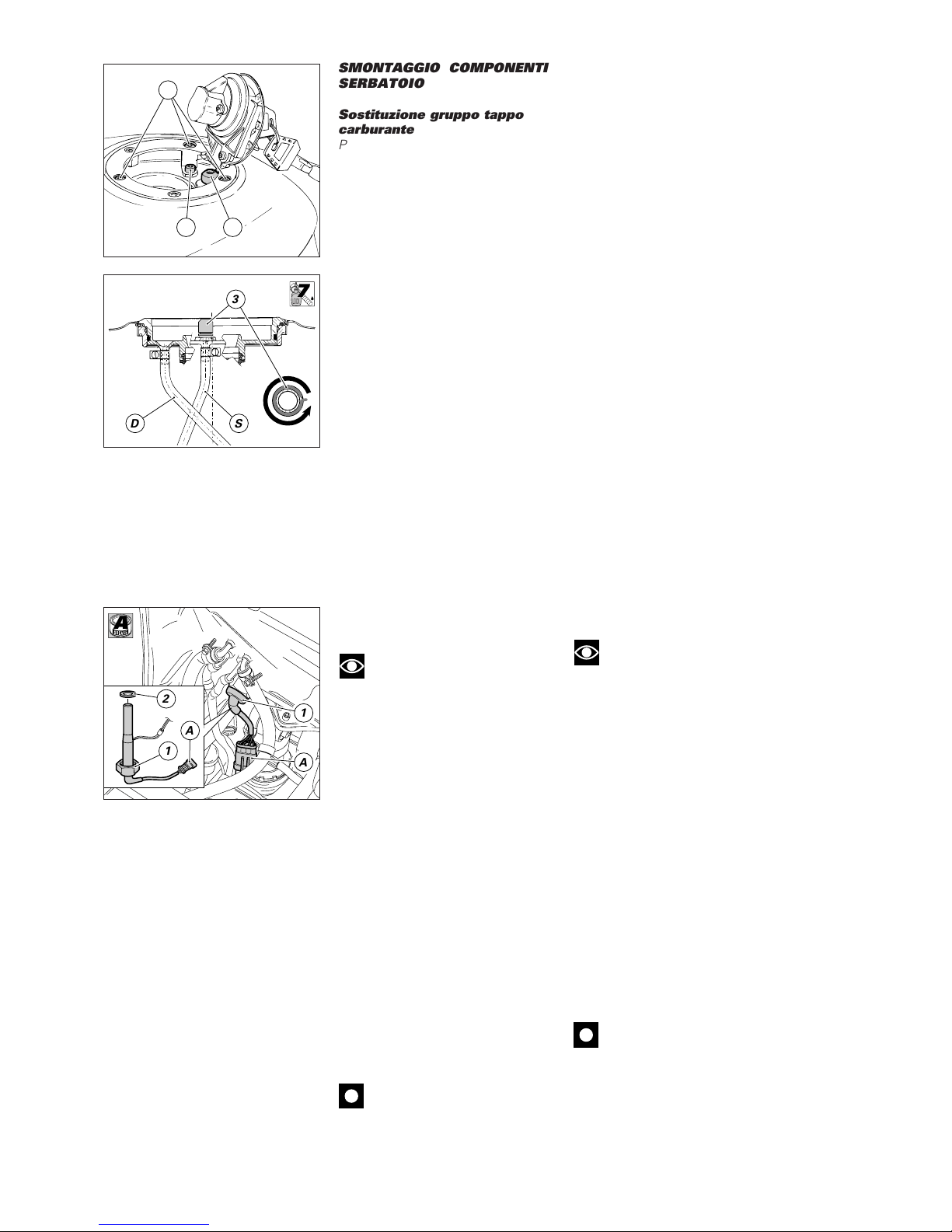
72 Mototelaio / Frame
Changing the fuel sensor
Note
The fuel sensor is connected
to the fuel pump inside the fuel
tank. To disconnect the sensor from
the pump, remove the tank filler
flange as described in “Changing
the fuel filter” in the
“Maintenance” section.
❍
Disconnect the sensor connector
(A) from the wiring.
❍
Remove the sensor from the fuel
tank.
▲
Lubricate the thread of the fuel
tank fitting with the specified
grease and fit a new seal (2) to the
sensor nut (1).
▲
Insert the cable with its
connector for the pump into the fuel
tank and install the sensor.
▲
Tighten the sensor to the
specified torque. The connector
cable (A) must be pointing to the
tank rear side.
Caution
Do not overtighten the
sensor, otherwise it might break.
Sostituzione indicatore livello
carburante
Note
L’indicatore di livello è
collegato, internamente al
serbatoio, alla pompa carburante.
Per staccare la connessione dalla
pompa è necessario rimuovere la
flangia del tappo come descritto al
capitolo “Sostituzione filtro
benzina” della sezione
“Manutenzione”.
❍
Staccare la connessione (A)
dell’indicatore dal cablaggio
principale.
❍
Rimuovere l’indicatore dal
serbatoio.
▲
Lubrificare con grasso prescritto il
filetto del raccordo sul serbatoio
quindi installare una guarnizione
nuova (2) nel dado (1) dell’indicatore.
▲
Introdurre il cavo con connettore
per la pompa nel serbatoio e
montare l’indicatore.
▲
Serrare l’indicatore alla coppia di
serraggio prescritta orientando il
cavo del connettore (A) verso la
parte posteriore del serbatoio.
Importante
Un serraggio eccessivo può
procurare la rottura dell’indicatore.
1
2 3
;;;;;
;;;
;
;;;
;;;
;;
;;
;;
;;
;
;
;
;;;
;
;;;;;;;
;
;
;
;;;
;;
;;;;
;;
;
;;
;;
;;;
;;
;;
;;;;
;;;
;
;
;
;
;
;
3
D S
A
2
A
1
1
7
LOCK
A
SMONTAGGIO COMPONENTI
SERBATOIO
Sostituzione gruppo tappo
carburante
Per rimuovere il gruppo tappo dal
serbatoio procedere nel modo
seguente:
❍
aprire il tappo di carico;
❍
svitare le 3 viti (1) esterne che
fissano la ghiera al pozzetto del
serbatoio;
❍
svitare la vite (2) antifurto interna;
❍
rimuovere il tappo completo;
All’interno del pozzetto del tappo si
trova il gommino (3) di sfiato.
▲
In caso di sostituzione, applicare
uniformemente su tutto il perimetro
della gola del gommino (3) un
adesivo istantaneo.
▲
Installare il gommino facendolo
aderire perfettamente nella sede
del pozzetto.
REMOVING FUEL TANK
COMPONENTS
Changing the fuel filler cap
assembly
To remove the fuel filler cap
assembly, proceed as follows:
❍
Undo the filler cap.
❍
Unscrew the 3 outer screws (1)
fixing the ring nut to the filler cap
recess.
❍
Unscrew the anti-theft screw (2)
on the inside.
❍
Remove the complete filler cap
assembly.
A breather hose seal (3) is seated
inside the filler recess.
▲
When fitting a new seal, apply a
uniform film of speed bonder along
the groove that accommodates the
seal (3).
▲
Fit the seal and make sure that it
is properly seated in the groove in
the recess.
Page 73
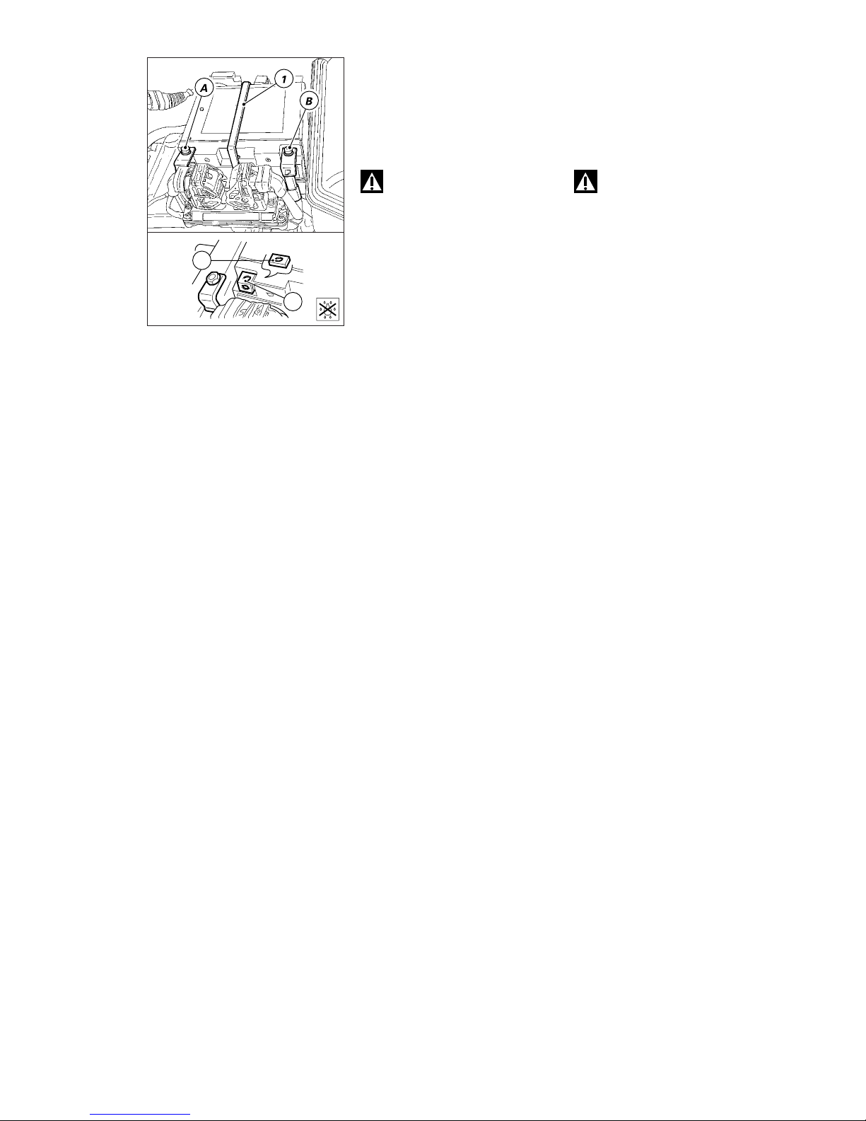
Mototelaio / Frame 73
SMONTAGGIO BATTERIA
❍
Rimuovere l'elastico (1) di
fissaggio batteria al supporto.
❍
Staccare sempre per primo il
terminale negativo NERO (A) poi
quello positivo ROSSO (B).
Attenzione
Le batterie producono dei gas
esplosivi: tenerle lontano da fonti di
calore e dal fuoco. Sistemare la
batteria in un luogo ben ventilato.
Portare sempre occhiali e guanti di
protezione quando si opera vicino
alla batteria.
❍
Rimuovere la batteria dal
supporto facendo attenzione a non
perdere gli inserti filettati (2)
presenti all'interno delle staffe (3) di
fissaggio terminali.
▲
Quando si rimonta la batteria è
necessario applicare nella zona di
contatto dei terminali sui poli
batteria protettivo per contatti
elettrici e serrare saldamente le viti
di fissaggio.
2
3
REMOVING THE BATTERY
❍
Remove the elastic strap (1) fixing
battery to battery mount.
❍
Always disconnect the BLACK
negative (A) first and then the RED
positive terminal (B).
Warning
Batteries produce explosive
gases. Store batteries in well
ventilated conditions away from
sources of heat or naked flames.
Always wear safety goggles and
gloves when handling batteries.
❍
Take the battery out of its mount
taking care not to lose the threaded
inserts (2) inside the terminal
brackets (3).
▲
At reassembly, spread a film of
protective grease for electrical
contacts on the battery terminals.
Tighten the terminal screws
securely.
Page 74
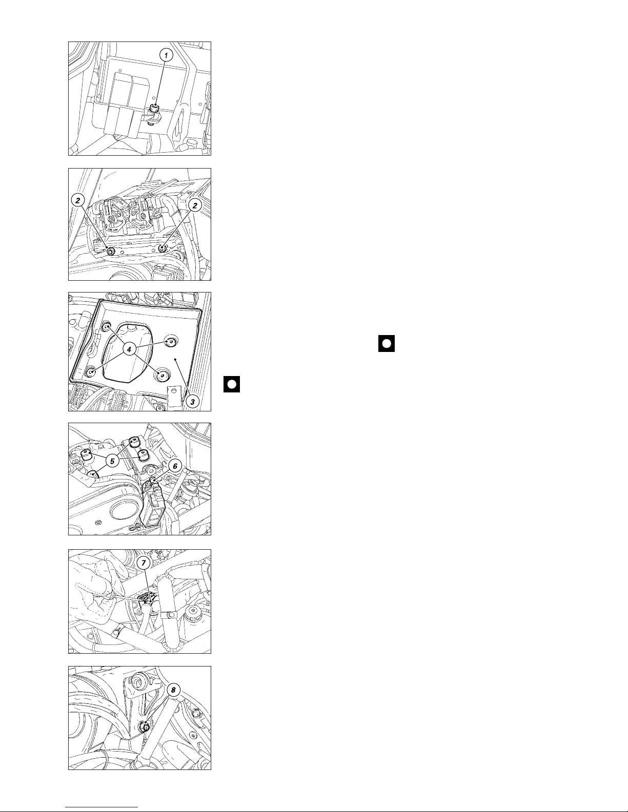
74 Mototelaio / Frame
REMOVING THE BATTERY
MOUNT
❍
Remove the battery as described
in “Removing the battery”.
❍
Loosen the screw (1) and remove
the relay holders. Do not disconnect
relays from the electrical system.
▲
At reassembly, make sure to fit
relay holders as shown in the figure.
❍
Unscrew the two screws (2) and
remove the injection CPU, but leave
it connected.
❍
Remove the battery rubber holder
(3).
❍
Unscrew the four screws (4) and
remove the battery mount.
❍
Remove the vertical head and
battery mount bracket damping
pads (5), if necessary.
❍
Slide pins (6) out of the relevant
seals and remove the fuse box from
bracket.
❍
Set the starter contactor elastic
support (7) apart from the bracket
and leave it connected.
❍
Undo the two nuts (8) and take
the bracket out of the vertical head.
Caution
At reassembly follow
description given under
“Arrangement of wiring on the
frame”.
SMONTAGGIO SUPPORTO
BATTERIA
❍
Rimuovere la batteria come
descritto al capitolo "Smontaggio
batteria".
❍
Svitare la vite (1) e rimuovere i
supporti porta relè, lasciando questi
ultimi collegati all'impianto elettrico.
▲
Fare attenzione nel rimontaggio a
rimontare i supporti relè nello
stesso ordine riportato in figura.
❍
Svitare le due viti (2) e rimuovere
la centralina iniezione, lasciandola
collegata all'impianto.
❍
Rimuovere la base in gomma (3)
di appoggio batteria.
❍
Svitare le quattro viti (4) e
rimuovere il supporto batteria.
❍
Eventualmente sostituire i quattro
supporti antivibranti (5) posizionati
sulla testa verticale e sulla staffa
supporto batteria.
❍
Rimuovere la scatola portafusibili
della staffa sfilando i pioli (6) dai
rispettivi gommini.
❍
Separare il supporto elastico (7)
teleruttore avviamento dalla staffa,
lasciandolo collegato all'impianto.
❍
Svitare i due dadi (8) di fissaggio
staffa e rimuoverla dalla testa
verticale.
Importante
Durante il rimontaggio fare
attenzione al posizionamento dei
cavi dall'impianto elettrico,
riposizionarli come descritto in
"Posizionamento cavi impianto
elettrico".
Page 75
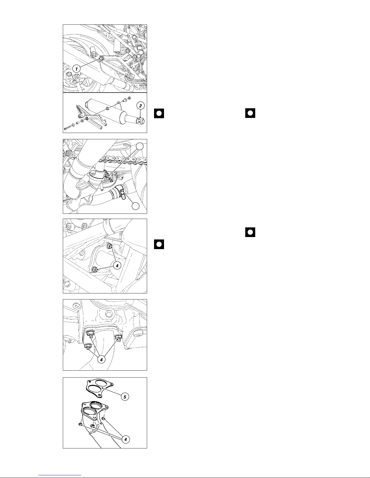
Mototelaio / Frame 75
REMOVING THE EXHAUST
SYSTEM
❍
Unscrew and remove the screw
(1) holding the silencer to the
support of the pillion rider footpeg.
▲
At reassembly, ensure that all
parts are refitted as shown in the
exploded view.
❍
Loosen the screw on the tie (2)
joining the silencer and the
horizontal exhaust pipe. Remove
the silencer.
Caution
At reassembly make sure not
to damage the aluminum gasket
placed between silencer and
horizontal exhaust pipe.
❍
Loosen the screw on the tie (3)
joining the horizontal and vertical
exhaust pipes.
❍
Repeat procedure on the other
silencer.
❍
Loosen and remove the nuts (4)
fixing flange to head.
❍
Disconnect the horizontal exhaust
pipe from the head and from the
vertical pipe and keep the gasket (5).
❍
Remove the vertical exhaust pipe
from the head and keep the gasket
(5).
Caution
Block off the exhaust ports on
the cylinder head to prevent dirt and
foreign objects from entering the
combustion chamber.
3
2
SMONTAGGIO SISTEMA DI
SCARICO
❍
Svitare e rimuovere la vite (1) di
fissaggio dal silenziatore al supporto
portapedana passeggero.
▲
Nel rimontaggio verificare che
tutti i particolari risultino montati
come mostra l'esploso.
❍
Allentare la vite sulla fascetta (2)
di tenuta tra silenziatore e tubo di
scarico orizzontale e sfilare il
silenziatore.
Importante
Durante il rimontaggio fare
attenzione a non danneggiare la
guarnizione in alluminio posta tra
silenziatore e tubo di scarico
orizzontale.
❍
Allentare la vite sulla fascetta (3)
di tenuta tra tubo orizzontale e tubo
verticale.
❍
Eseguire la stessa procedura per
l’altro silenziatore.
❍
Allentare e rimuovere i dadi (4) di
fissaggio della flangia alla testa
❍
Sfilare il tubo di scarico
orizzontale dalla testa e dal
tubo verticale; recuperare la
guarnizione (5).
❍
Sfilare il tubo di scarico verticale
dalla testa e recuperare la
guarnizione (5).
Importante
Otturare i condotti di scarico
sulla testa per evitare che corpi
estranei entrino nella camera di
scoppio.
Page 76
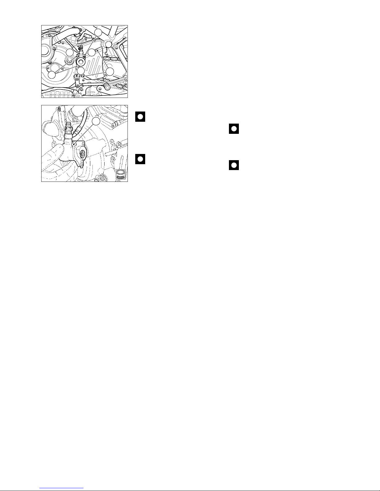
76 Mototelaio / Frame
SMONTAGGIO COPERCHIO
PIGNONE E RINVIO FRIZIONE
❍
Svitare le 2 viti (1) di fissaggio
coperchio pignone e rimuoverlo.
▲
Nel rimontaggio inserire
l’estremità superiore del coperchio
sotto al dentino del rinvio frizione.
❍
Svitare le 3 viti (2) di fissaggio del
rinvio frizione al motore.
❍
Sfilarlo dal coperchio sinistro
facendo attenzione alla guarnizione
OR (3) fissata al suo interno.
Importante
Non azionare la leva frizione
quando il gruppo di rinvio è stato
rimosso dal motore. Ciò potrebbe
causare la fuoriuscita del pistoncino
con conseguente perdita di fluido.
Importante
Nel montaggio lubrificare la
guarnizione OR e serrare le viti (2) in
sequenza A - B - C - A - B.
1
2
C
2
A
B
3
D
REMOVING THE SPROCKET
COVER AND THE CLUTCH
TRANSMISSION
❍
Remove the 2 retaining screws
(1) and remove the sprocket cover.
▲
At reassembly, insert the upper
edge of the cover under the clutch
transmission tooth.
❍
Unscrew the 3 screws (2) fixing
the clutch transmission to the
engine.
❍
Pull out from the left cover. Make
sure not to damage the O-ring (3)
into the transmission unit.
Caution
Do not operate the clutch
lever when the actuating piston is
disassembled otherwise piston will
come out and fluid will leak.
Caution
Lubricate the O-ring before
reassembly and tighten screws (2)
in A-B-C-A-B sequence.
Page 77
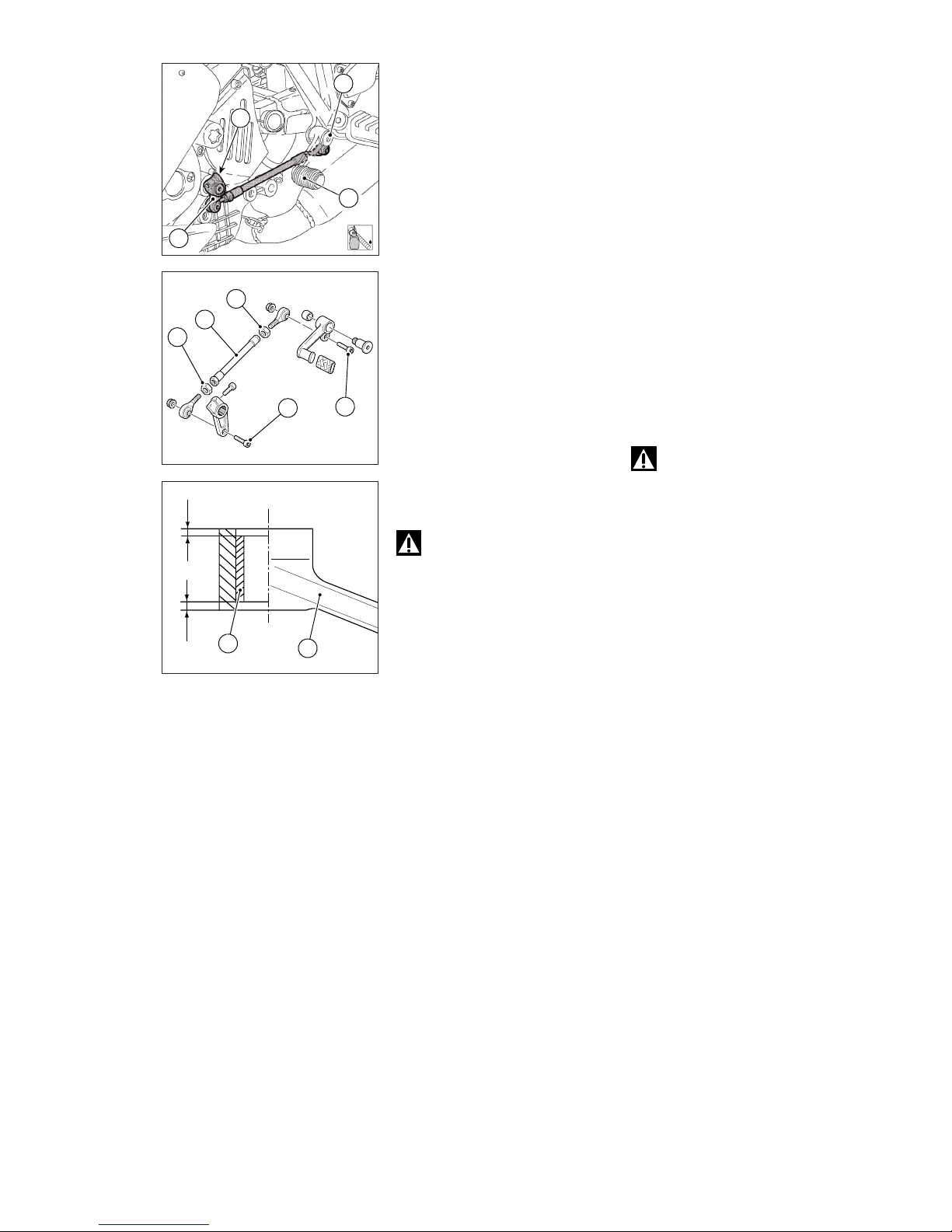
Mototelaio / Frame 77
SMONTAGGIO COMANDO
CAMBIO
❍
Svitare e rimuovere il perno (1) di
fissaggio pedale cambio (2).
❍
Svitare e rimuovere la vite di
ritegno (3) e divaricare il morsetto
della vite (4).
❍
Contrassegnare la posizione della
leva (4) rispetto all’alberino di
selezione marce, quindi sfilare la
leve dal motore.
❍
Rimuovere il gruppo comando
cambio dal veicolo.
Scomposizione comando
cambio
❍
Per rimuovere l’astina di rinvio (5)
della leva (4) e dal pedale (2) svitare
e rimuovere le viti (6) e (7).
❍
Allentare i controdadi (8) e (9) e
rimuovere gli snodi sferici dall’astina
di rinvio.
❍
In caso di sostituzione della
boccola (10) interna al pedale (5),
eseguire il montaggio della boccola
nuova utilizzando per l’introduzione
una pressa e portandola alla quota di
2 mm dalla faccia esterna del pedale.
Attenzione
Dopo aver eseguito un
intervento sul comando cambio
posteriore occorre verificare la
posizione del pedale freno.
Per eseguire la regolazione della
posizione del pedale freno
posteriore seguire le istruzioni
riportate nel capitolo “Registrazione
posizione pedale comando cambio
e freno posteriore” della sezione
“Registrazioni e regolazioni”.
▲
Per il rimontaggio eseguire in
ordine inverso le operazioni eseguite
per lo smontaggio del gruppo.
Applicare frenafiletti sulla vite (3), sul
perno (1) e sulla vite (6) quindi
bloccarli alla coppia prescritta.
3
1
2
4
2 mm2 mm
10
5
9
8
5
6
7
1
LOCK
REMOVING THE
GEARCHANGE
❍
Loosen and remove shaft (1)
securing gearchange pedal (2).
❍
Loosen and remove screw (3) and
open clamp on screw (4).
❍
Mark the position of lever (4) with
respect to gear selector shaft and
remove linkages from the engine.
❍
Remove the gearchange
assembly from the vehicle.
Disassembling the gearchange
❍
Loosen and remove screws (6)
and (7) to remove rod (5) from lever
(4) and pedal (2).
❍
Loosen lock nuts (8) and (9) and
remove ball joints from the rod.
❍
Should bushing (10) inside pedal
(5) need to be replaced, fit the new
bushing using a press and bring it to
a value of 2 mm from the outer
pedal surface.
Warning
After any service on the rear
gearchange pedal it is
recommended to check brake pedal
position. Adjust rear brake pedal
position as indicated in “Adjusting
the position of the gear change and
rear brake pedals” under “Settings
and adjustments” section.
▲
Reverse disassembly procedure
to reassemble the unit. Apply
threadlocker on screw (3), on shaft
(1) and on screw (6), then tighten to
the specified torque.
Page 78
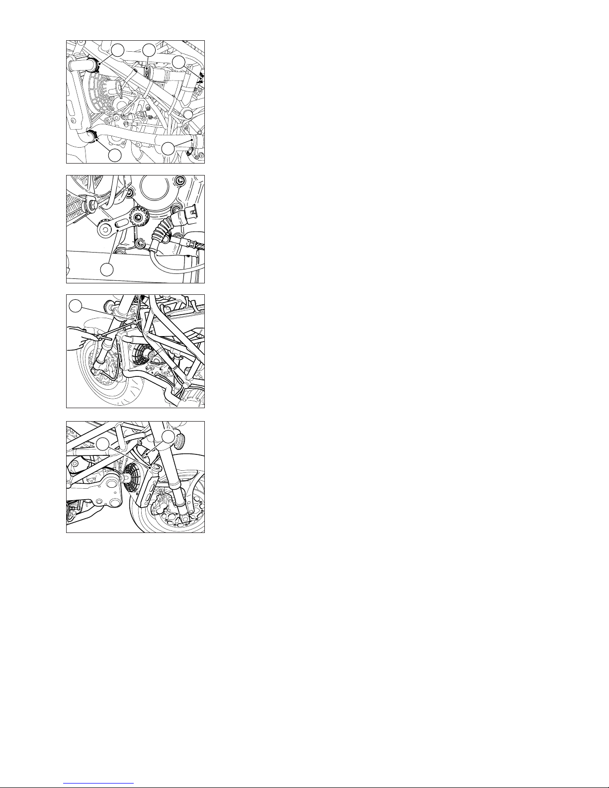
78 Mototelaio / Frame
4
2
2
1
1
1
3
6
5
DISCONNECTING THE
COOLING SYSTEM
Before disconnecting the cooling
system hoses, drain off the coolant
as specified in “Changing the
coolant” in the “Maintenance”
section.
Proceed as follows:
❍
Loosen the ties (1) on the
radiator-heads hose.
❍
Remove the hose.
❍
Loosen the tie (2) on the
thermostat-radiator hose and
disconnect the hose from the
cooler.
❍
Disconnect the radiator bracket
(3) from the horizontal head and
move radiator forward.
❍
Unscrew the screw (4) fitting
radiator to frame.
❍
Loosen the clamping tie (5) on
the fluid recovery to radiator hose.
❍
Disconnect the bracket (6) fixing
radiator to frame and remove the
radiator.
SMONTAGGIO IMPIANTO DI
RAFFREDDAMENTO
Prima di staccare le tubazioni è
necessario scaricare il liquido
refrigerante seguendo le istruzioni
riportate al paragrafo “Sostituzione
liquido refrigerante” del capitolo
“Manutenzione”. Procedere poi nel
modo seguente:
❍
allentare le fascette (1) sul tubo
collegamento teste-radiatore;
❍
sfilare il tubo e rimuoverlo dal
veicolo;
❍
allentare la fascetta (2) sul tubo
collegamento termostato-radiatore
e sfilarlo da quest’ultimo;
❍
staccare la staffetta (3) di
sostegno del radiatore dalla testa
orizzontale e spostare in avanti il
radiatore.
❍
Svitare la vite (4) di fissaggio
radiatore al telaio.
❍
Allentare la fascetta (5) di
fissaggio dalla tubazione recupero
liquidi al radiatore.
❍
Staccare la staffa (6) di sostegno
radiatore al telaio e rimuovere il
radiatore.
Page 79
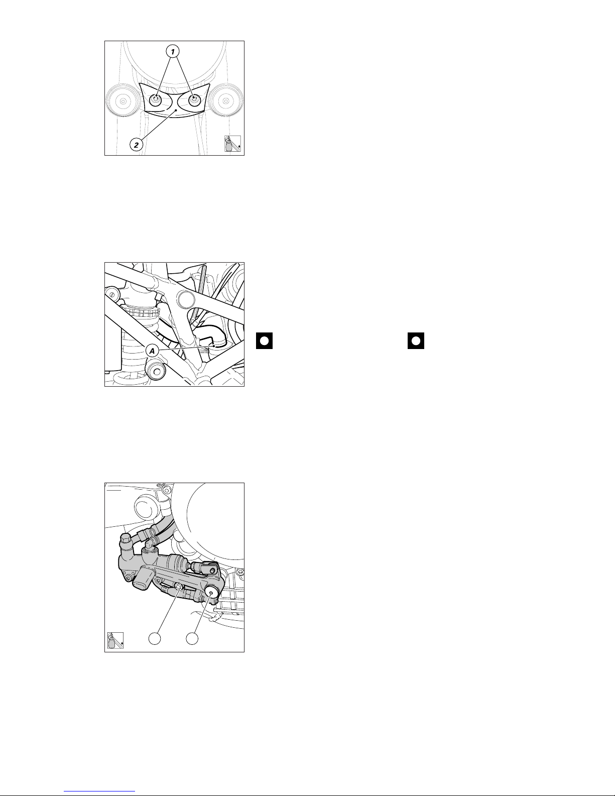
Mototelaio / Frame 79
12
5
LOCK
2
LOCK
SMONTAGGIO AVVISATORI
ACUSTICI
❍
Staccare le connessioni del
cablaggio principale degli avvisatori
acustici.
❍
Svitare le due viti (1) e rimuovere
la protezione in plastica (2) e i due
avvisatori acustici unitamente alla
loro staffa di supporto.
▲
Nel rimontaggio delle viti (1)
applicare frenafiletti sul filetto e
serrare alla coppia prescritta.
SMONTAGGIO TUBO SFIATO
VAPORI BASAMENTO
❍
Allentare la fascetta (A) e sfilare il
tubo di sfiato vapori dal raccordo sul
basamento.
Importante
Otturare l’apertura del
raccordo per evitare che corpi
estranei entrino nel basamento.
SMONTAGGIO SUPPORTO
POMPA - PEDALE FRENO
POSTERIORE
❍
Svitare il perno (1) del pedale
freno e la vite (2) di fissaggio
posteriore del supporto pompapedale freno.
▲
Nel rimontaggio applicare
adesivo per bloccaggi coassiali sul
filetto del perno (1) e della vite (2).
❍
Staccare il supporto dal motore
lasciando i tubi freno e il cavo
dell’interruttore stop posteriore
collegati ai rispettivi impianti.
REMOVING THE WARNING
HORNS
❍
Disconnect the warning horns
from the main cable.
❍
Undo the two screws (1), remove
the plastic cover (2) and the two
warning horns with relevant
brackets.
▲
When refitting the screws (1),
apply some threadlocker and
tighten to the specified torque.
DISCONNECTING THE
BREATHER PIPE
❍
Loosen the tie (A) and disconnect
the breather pipe from the
crankcase fitting.
Caution
Block off the fitting opening to
prevent dirt and foreign objects
from entering the crankcase.
REMOVING THE REAR BRAKE
PEDAL AND THE CYLINDER
SUPPORT
❍
Unscrew the brake pedal pin (1)
and the rear fastening screw (2) of
the brake pedal-cylinder support.
▲
At reassembly, apply retaining
compound to the pin (1) and screw
(2) threads.
❍
Disconnect the support from the
engine but leave the brake hoses
and the stop light switch cable
connected.
Page 80
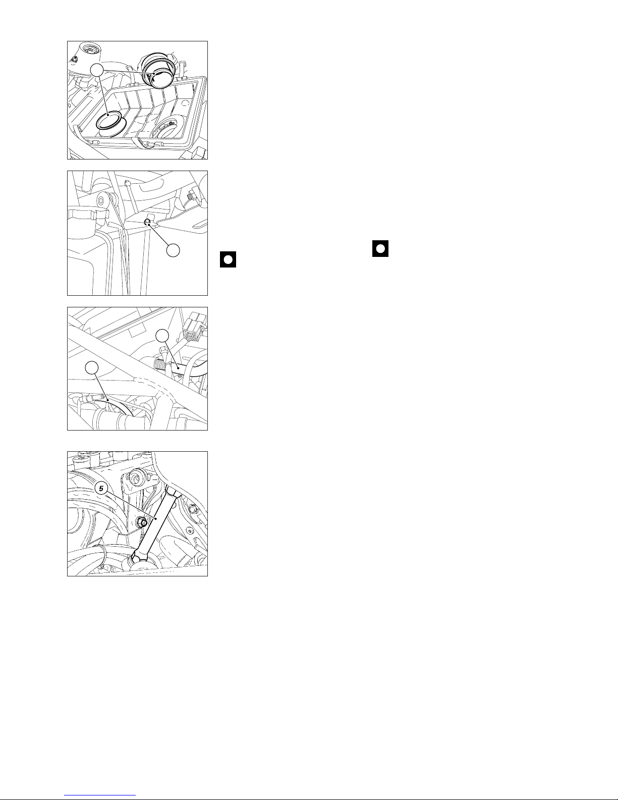
80 Mototelaio / Frame
REMOVING THE AIR BOX
❍
Remove the cover and the filter
cartridge as described in “Changing
the air filter” in the “Maintenance”
section.
❍
Turn the intake manifolds (1)
counterclockwise to release them
from the retaining spring into the
filter box. Remove the intake
manifolds.
❍
Undo the front retaining screw (2)
fitting the box behind the frame.
❍
Release the drain (3) and the oil
breather pipes (4) connected to the
bottom of the air filter box.
❍
Working from the frame side,
remove the studs (5) fitting air filter
box to frame and remove the box.
Caution
Lubricate with alcohol the
seals positioned close to the studto-frame connection not to damage
them.
SMONTAGGIO SCATOLA
FILTRO ARIA
❍
Rimuovere il coperchio e la
cartuccia filtro aria come descritto al
capitolo "Sostituzione filtro aria" della
sezione "Manutenzione".
❍
Ruotare in senso antiorario i
collettori di aspirazione (1) per
liberarli dalla molla di ritegno, posta
all'interno della scatola filtro, ed
estrarli.
❍
Svitare la vite anteriore (2) di
fissaggio della scatola dietro al telaio.
❍
Liberare il tubo di drenaggio (3) e
il tubo vapori olio (4) collegati sul
fondo della scatola filtro.
❍
Sfilare le colonnette (5) che
fissano la scatola al telaio e
rimuovere la scatola filtro aria.
Importante
Per non danneggiare i gommini
montati in corrispondenza del
fissaggio della colonnetta al telaio, si
consiglia di lubrificarli con alcool.
2
4
3
1
Page 81
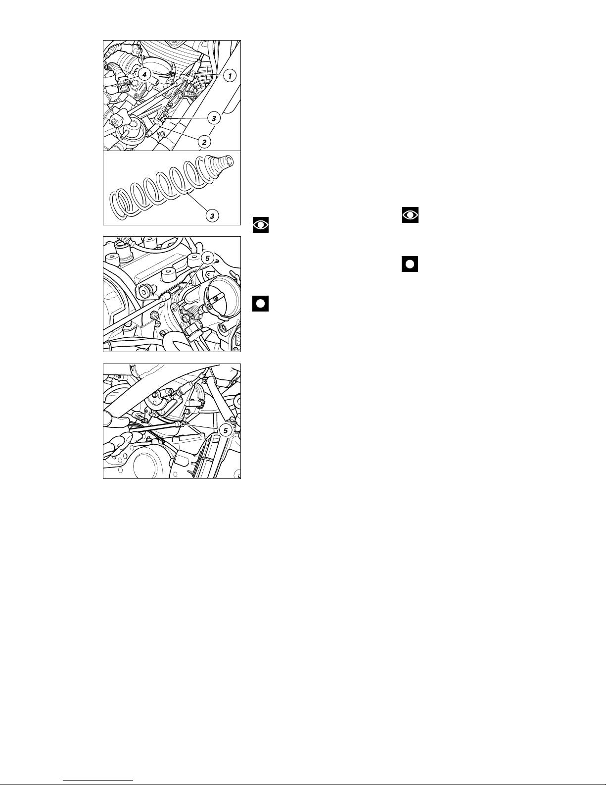
Mototelaio / Frame 81
SMONTAGGIO CORPO
FARFALLATO
❍
Allentare il dado di fermo (1), e
rimuovere il cavo comando gas
liberandolo dalla carrucola di
comando.
❍
Allentare il controdado e liberare
il cavo starter (2), dal musetto dalla
leva di comando sul corpo farfallato.
❍
Estrarre la molla (3).
❍
Scollegare le connessioni (4) al
cablaggio.
❍
Allentare le fascette (5) sui
collettori di aspirazione.
❍
Sfilare il corpo farfallato dai
collettori di aspirazione.
Note
In caso di sostituzione delle
trasmissioni comando acceleratore
e starter, quando si procede
all’installazione sul veicolo, è
necessario posizionarle come in
origine.
Importante
I cavi di comando acceleratore
e starter non devono essere fissati
da alcuna fascetta.
REMOVING THE THROTTLE
BODY
❍
Loosen the lock nut (1), release
the throttle cable from the control
pulley and disconnect it.
❍
Loosen the lock nut and release
the choke cable (2) from the control
lever front part on the throttle body.
❍
Remove the spring (3)
❍
Disconnect the connections (4)
from wiring.
❍
Loosen the ties (5) on the intake
manifolds.
❍
Disconnect the throttle body from
the intake manifolds.
Note
When fitting new throttle and
choke cables, fit them in their
original positions.
Caution
Do not fix throttle and choke
cables with ties or clamps.
Page 82
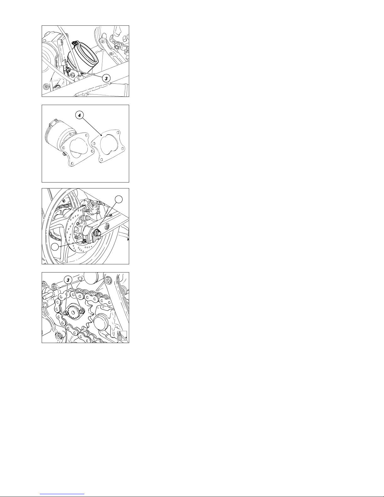
82 Mototelaio / Frame
1
2
1
LOCK
SMONTAGGIO COLLETTORE
ASPIRAZIONE
❍
Rimuovere il collettore di
aspirazione dalla testa verticale
svitando e rimuovendo i 2 dadi (3).
❍
Recuperare la guarnizione (4) e
tappare il condotto di scarico della
testa verticale e il collettore della
testa orizzontale.
SMONTAGGIO PIGNONE
CATENA
❍
Allentare il dado (1) sul perno
ruota posteriore.
❍
Svitare completamente le viti (2)
di registro tensione catena e
spingere in avanti la ruota.
❍
Inserire una marcia bassa per
contrastare l’operazione e svitare le
due viti (3) sulla piastrina ferma
pignone.
❍
Rimuovere quest’ultima
dall’albero secondario cambio.
❍
Sfilare il pignone con catena
dall’albero secondario cambio e poi
scarrucolare la catena dal pignone
stesso.
▲
Nel rimontaggio applicare
frenafiletti debole sul filetto delle
viti (3).
REMOVING THE INTAKE
MANIFOLD
❍
Undo the 2 nuts (3) and remove
the intake manifold from the vertical
head.
❍
Keep the gasket (4) and block off
the opening of the exhaust manifold
of the vertical head and the
manifold of the horizontal head.
REMOVING THE CHAIN
SPROCKET
❍
Loosen the nut (1) on the rear
wheel shaft.
❍
Unscrew the chain tensioner
bolts (2) fully and then push the
wheel forward.
❍
Engage a low gear to provide
resistance for the next operation.
Unscrew the 2 bolts (3) on the
sprocket stop plate.
❍
Remove the stop plate from the
gearbox transmission shaft.
❍
Pull out the sprocket and chain
from the gearbox transmission
shaft. Run the chain out off the
sprocket.
▲
At reassembly, apply lowstrength threadlocker on the screw
threads (3).
Page 83
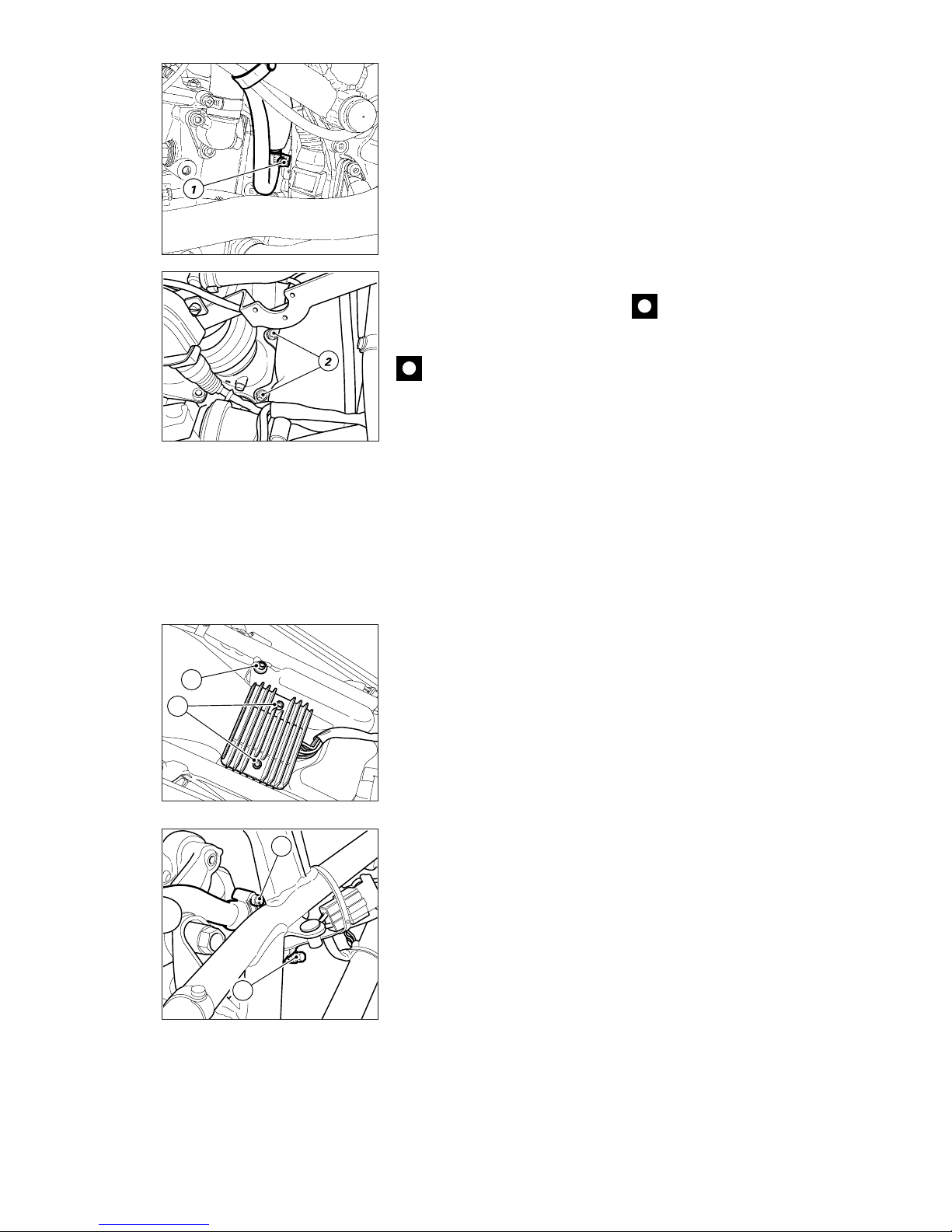
Mototelaio / Frame 83
REMOVING THE COOLANT
EXPANSION TANK
❍
Drain the circuit as described in
“Changing the coolant” under
section “Maintenance”.
❍
Loosen the tie (1) on the pipe
connecting expansion tank to
radiator and slide out the pipe.
❍
Open the elastic strap and slide
out the tank breather pipe.
❍
Undo the two screws (2) fixing
the expansion tank bracket to the
horizontal head. Remove the tank.
Caution
Should tank breather pipe
have come out, at reassembly route
it as described in “Hoses and
Bowden cables routing on the
frame” under section “Frame”.
4
3
SMONTAGGIO SERBATOIO
D'ESPANSIONE ACQUA
❍
Svuotare l'impianto di
raffreddamento come descritto al
capitolo "Sostituzione liquido
refrigerante" della sezione
"Manutenzione".
❍
Allentare la fascetta (1) sulla
tubazione di collegamento serbatoio
di espansione radiatore e sfilare il
tubo.
❍
Aprire la fascetta elastica e sfilare
il tubo di sfiato serbatoio.
❍
Svitare le due viti (2) di fissaggio
staffa serbatoio espansione alla
testa orizzontale e rimuovere il
serbatoio.
Importante
In caso si sia sfilato il tubo di
sfiato serbatoio, durante il
rimontaggio, posizionarlo come
descritto al capitolo "Disposizione dei
tubi e delle trasmissioni flessibili sul
telaio" della sezione "Mototelaio".
5
6
REMOVING THE OIL
BREATHER TANK
❍
Loosen the screws (3) fixing the
regulator to the oil breather tank and
move it in order to make the
following operations easier, but
leave it connected to wiring.
❍
Undo the screw (4) fixing tank to
frame.
❍
Loosen the tie (5) fixing air filter
box pipe to oil breather tank and
slide the pipe out of the tank.
❍
Loosen the tie (6) fixing oil
breather valve to oil breather tank
and slide the pipe out.
❍
Remove the oil breather tank.
If also connecting pipes need
removing, follow the instruction
given in “ Hoses and Bowden
cables routing on the frame ” under
section “Frame”.
SMONTAGGIO SERBATOIO
SFIATO VAPORI OLIO
❍
Svitare le viti (3) di fissaggio del
regolatore al serbatoio sfiato vapori
olio e spostarlo senza scollegarlo dal
cablaggio principale in modo tale
che non sia di intralcio per le
successive operazioni.
❍
Svitare la vite (4) di fissaggio
serbatoio al telaio.
❍
Allentare la fascetta (5) di
fissaggio tubo collegamento scatola
filtro aria-serbatoio sfiato olio e
sfilare il tubo da quest'ultimo.
❍
Allentare la fascetta (6) di
fissaggio tubo collegamento valvola
sfiato vapori olio - serbatoio sfiato
vapori olio e sfilare il tubo.
❍
Rimuovere il serbatoio sfiato
vapori olio.
In caso sia necessario rimuovere
anche i tubi di collegamento seguire
le istruzioni riportate nel capitolo
"Disposizione dei tubi e delle
trasmissioni flessibili sul telaio" della
sezione "Mototelaio".
Page 84
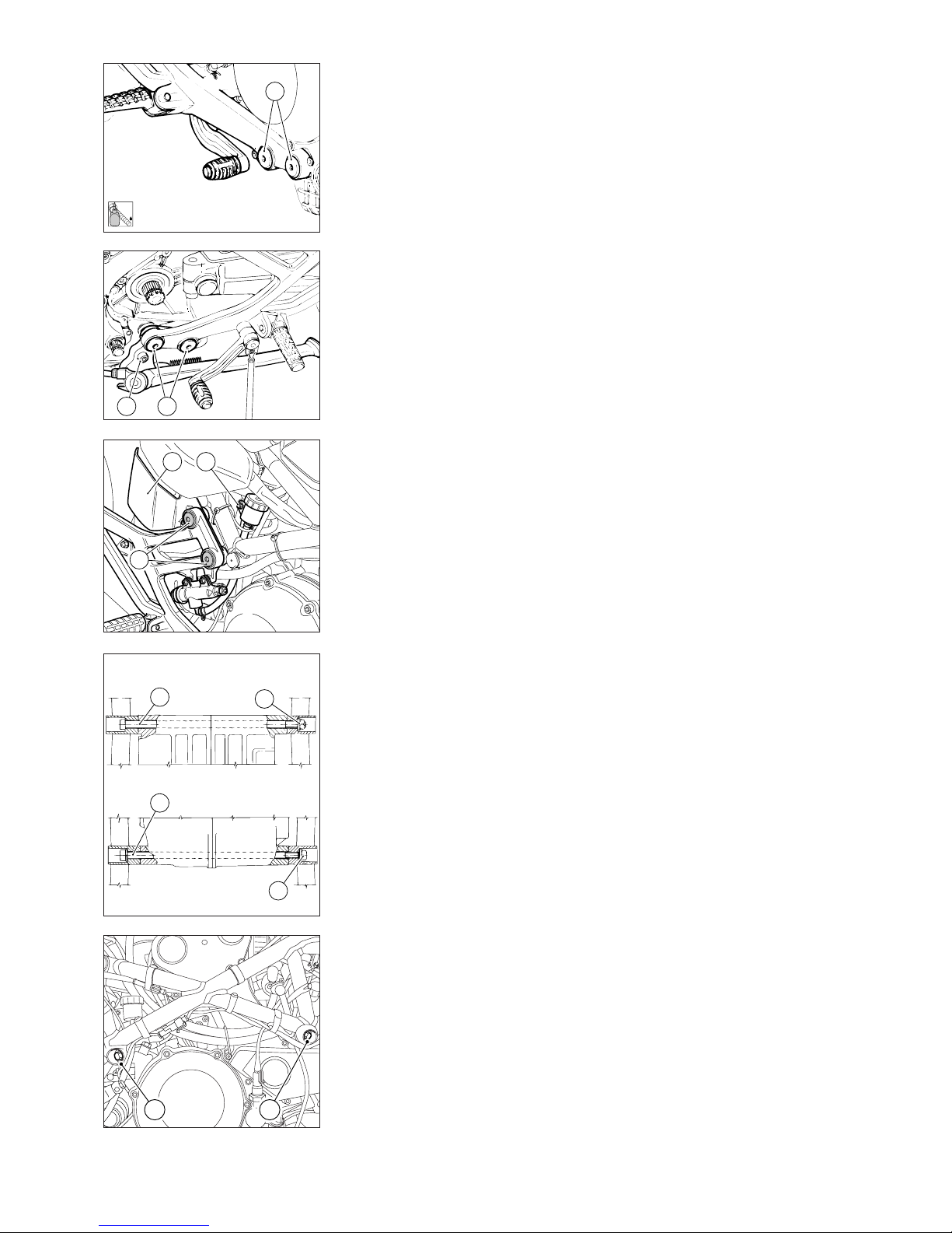
84 Mototelaio / Frame
A
AB
1
3
C
DE
ANT.
FRONT
POST.
REAR
Lato alternatore
Generator side
Lato frizione
Clutch side
1
2
4
3
5
LOCK
SMONTAGGIO MOTORE
❍
Svitare le viti di fissaggio (A) dei
supporti porta pedane su entrambi i
lati del motore e recuperare le
rosette distanziali interne. Sul lato
sinistro la vite anteriore fissa anche
la piastra di supporto del cavalletto
laterale.
❍
Il cavalletto laterale può rimanere
fissato al motore. Nel caso fosse
necessario rimuoverlo, svitare la vite
(B) di fissaggio sul motore e
scollegare il connettore del sensore
cavalletto dal cablaggio generale.
▲
Nel rimontaggio applicare
frenafiletti sulla filettatura delle viti
(A e B) ed installare, tra motore e
supporto, le rosette e il distanziale
in corrispondenza della vite
posteriore sinistra.
❍
Per agevolare la rimozione del
motore è consigliabile staccare
completamente i supporti porta
pedane dal telaio, svitando le viti (C)
di fissaggio, e recuperando le
rosette.
❍
Sul supporto lato destro è
montata la pompa con pedale di
comando del freno posteriore; per
evitare di separare i componenti,
svitare la vite (D) di fissaggio del
serbatoio liquido freno al telaio e
lasciarlo collegato all'impianto sul
supporto pedane.
Note per versione USA
Tra telaio e supporto pedana lato
destro è fissata la staffa di sostegno
del Canister (E).
❍
Rimuovere i tappi di protezione
dai tubi del telaio in prossimità dei
punti di fulcraggio del motore.
❍
Posizionare un supporto sotto al
motore.
❍
Svitare e rimuovere il dado (1), sul
lato frizione e sfilare la vite (2) di
fissaggio anteriore del motore.
REMOVING THE ENGINE
❍
Unscrew the retaining screws (A)
of the footpeg brackets on both
sides of the engine. Keep the
washers found on the inside. The
front screw on the left side also
holds the side stand plate.
❍
The side stand may be left
installed to the engine. If you need
to remove it, unscrew the screw (B)
that holds it to the engine and
disconnect the side stand sensor
from the wiring.
▲
At reassembly, use threadlocker
on the threads of screws (A and B).
Be sure to place the washers
between engine and brackets and
the spacer under the LH rear bolt.
❍
To ease engine removal, take the
footpeg brackets off the frame.
Unscrew their retaining screws (C)
and keep the washers.
❍
The RH side bracket holds the
rear brake master cylinder and
pedal. To leave them assembled,
unscrew the screw (D) fixing the
brake fluid reservoir to the frame
and leave it connected to the
system on the footpeg bracket.
Notes on the USA version
The Canister bracket (E) is held in
place between frame and footpeg
bracket on RH side.
❍
Extract the plastic plugs from the
frame tubes near the engine pivot
points.
❍
Place a stand under the engine.
❍
Unscrew and remove the nut (1)
at the clutch side and the front
engine mounting bolt (2).
Page 85
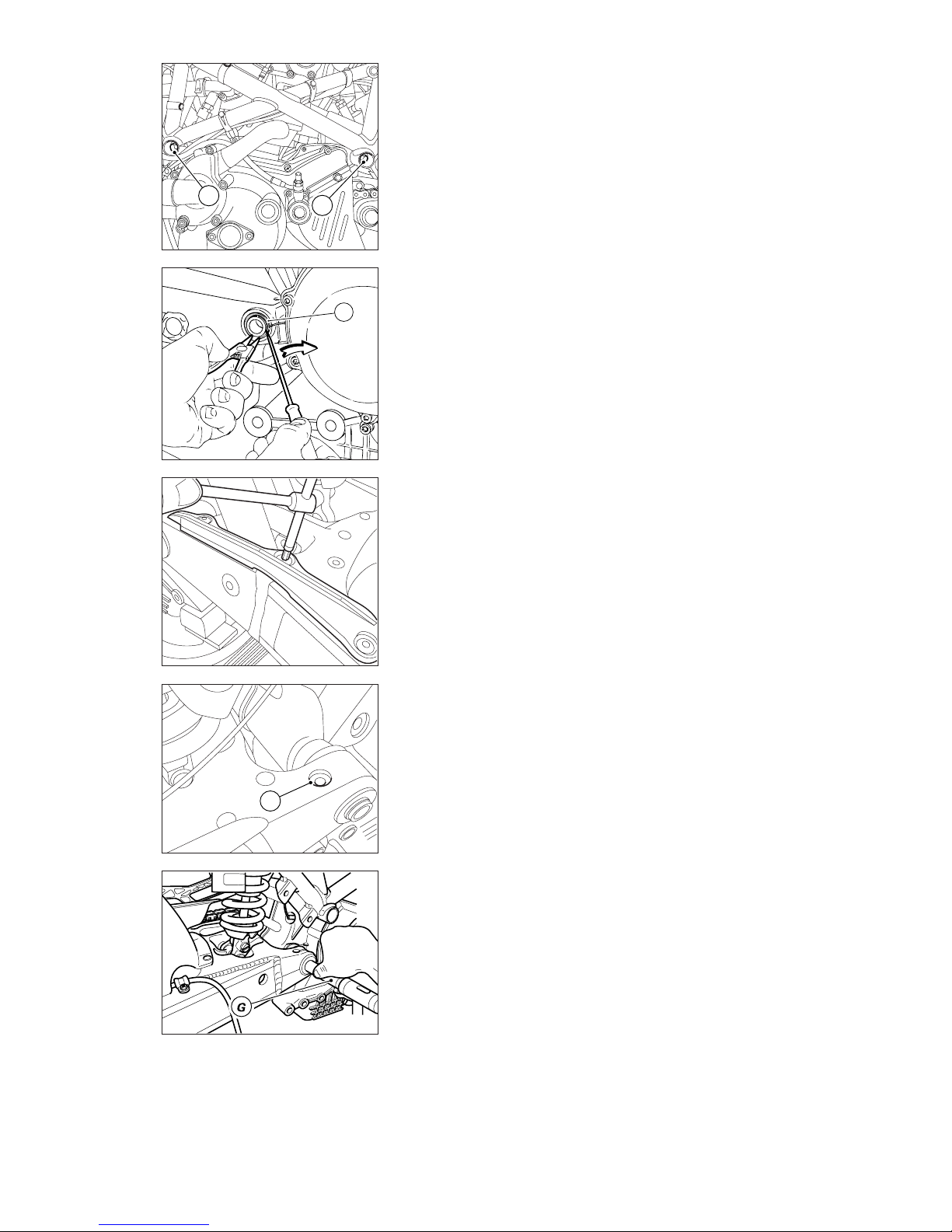
Mototelaio / Frame 85
❍
Undo and remove nut (3) at the
clutch side and rear engine
mounting bolt (4).
❍
Extract the plastic plugs from
both sides of swinging arm pivot
shaft.
❍
To free the swinging arm pivot
shaft, remove one of the two
circlips (F) that lock the shaft in
place at either end of the swinging
arm.
❍
Loosen the bolts (5) of the shaft
clamps on the swinging arm.
Remove the chain sliding shoe to
loosen the LH screw.
❍
Working from the right side, use a
suitably sized drift (G) to knock out
the pivot shaft by about half its
length.
❍
Svitare e rimuovere il dado (3) sul
lato frizione la vite (4) di fissaggio
posteriore del motore.
❍
Estrarre i tappi in plastica in
corrispondenza del fulcro del
forcellone da entrambi i lati.
❍
Per liberare il perno forcellone è
necessario rimuovere uno dei due
anelli elastici (F) che bloccano il
perno alle estremità del forcellone.
❍
Allentare le viti (5) sui morsetti di
serraggio del perno sul forcellone.
Per allentare la vite sul lato sx è
necessario smontare il pattino catena.
❍
Utilizzando una spina adatta (G)
spingere in fuori il perno forcellone
verso il lato sinistro fino a metà circa
della sua lunghezza.
5
F
2
4
Page 86
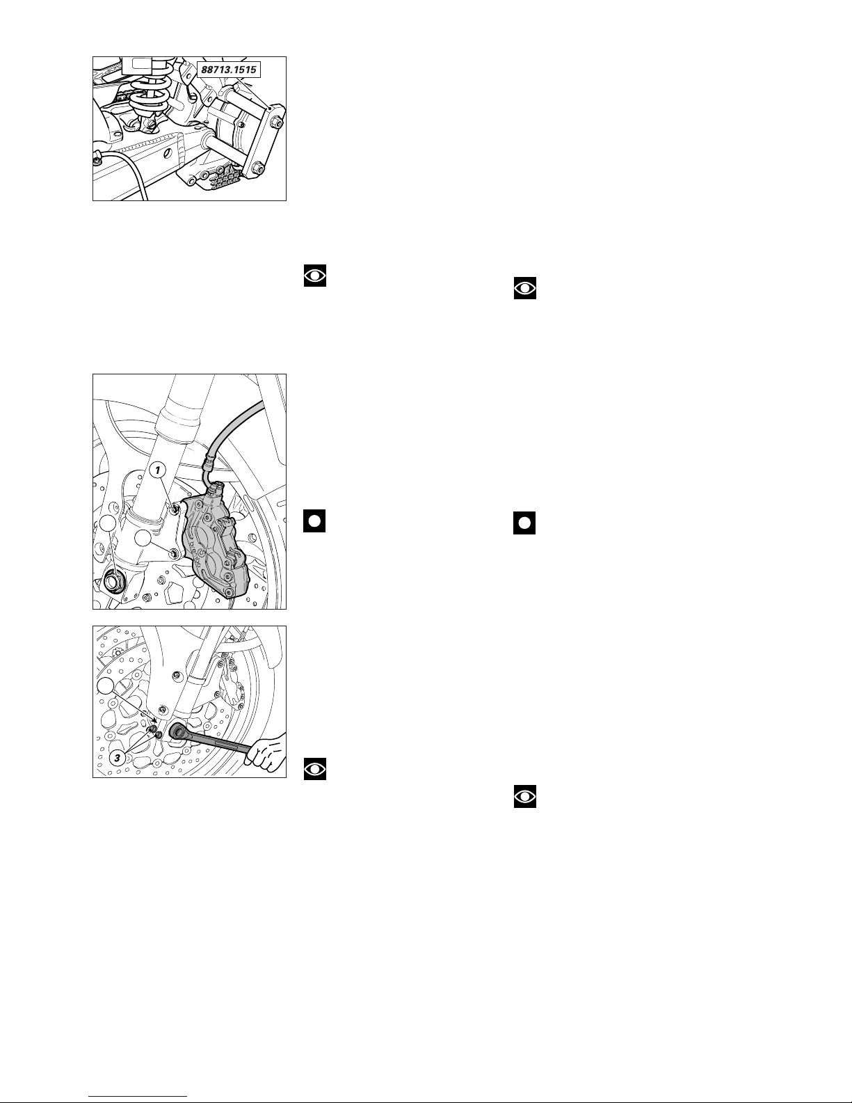
86 Mototelaio / Frame
❍
Slide out the upper screw (3) by
about half its length and insert the
service support part no. 88713.1515
on the right side.
❍
Tighten the bolt (5) on the RH
clamp of the swinging arm to clamp
the service support in place.
❍
Slide the swinging arm pivot shaft
and the upper bolt (3) fully out.
❍
Insert the other support from the
left side and clamp it in place with
bolt (5). Frame and swinging arm are
now locked in the proper position,
ready for reassembly of the engine.
❍
Remove the engine.
Note
For disassembly, overhaul
and reassembly of engine
components, see the “Engine”
section.
REMOVING THE FRONT
WHEEL
❍
Support the bike so that the
wheel to be removed is raised off
the ground.
❍
Unscrew the retaining bolts (1)
and remove the two brake calipers
from the fork legs.
Caution
Do not operate the brake lever
when the calipers are
disassembled. Operating the brake
lever when the calipers are
removed from their operating
position will cause the leakage of
brake fluid from the pad actuating
pistons.
❍
Unscrew and remove the nut (2)
from the LH end of the wheel shaft.
❍
Loosen the shaft pinch bolts (3)
on the fork legs.
❍
Working from the left side, use a
plastic hammer to knock the wheel
shaft out to the other side.
❍
Slide the wheel out and keep the
specer (4).
Note
Overhaul the wheel as per the
instructions given in “Front wheel
overhaul” in this section.
❍
Sfilare la vite superiore (3) fino a
metà ed inserire l’apposito supporto
88713.1515 sul lato destro.
❍
Bloccare la vite (5) sul morsetto
destro del forcellone serrando in
questo modo il supporto.
❍
Sfilare definitivamente il perno
forcellone e la vite superiore (3).
❍
Inserire l’altro supporto sul lato
sinistro e bloccarlo con la vite (5). In
questo modo il telaio e il forcellone
risulteranno posizionati, pronti per il
rimontaggio del motore.
❍
Sfilare il blocco motore.
Note
Per lo smontaggio, la
revisione e il rimontaggio dei
componenti del motore vedi
sezione “Motore”.
SMONTAGGIO RUOTA
ANTERIORE
❍
Supportare in modo adeguato il
motociclo per poter avere la ruota
da rimuovere sollevata da terra.
❍
Staccare le due pinze freno dai
gambali della forcella svitando le viti
(1) di fissaggio.
Importante
Non azionare la leva del freno
quando le pinze sono smontate. Ciò
potrebbe causare la perdita di fluido
dai pistoncini di spinta delle
pastiglie freno.
❍
Svitare e rimuovere il dado (2) sul
lato sinistro del perno ruota.
❍
Allentare le viti (3) di bloccaggio
perno sui gambali della forcella.
❍
Con mazzuolo di plastica ribattere
il perno ruota sul lato sinistro e poi
sfilarlo completamente dal lato
opposto.
❍
Sfilare la ruota e recuperare il
distanziale (4).
Note
Procedere alle operazioni di
revisione necessarie come descritto
al capitolo “Revisione ruota
anteriore” di questa sezione.
4
1
2
Page 87
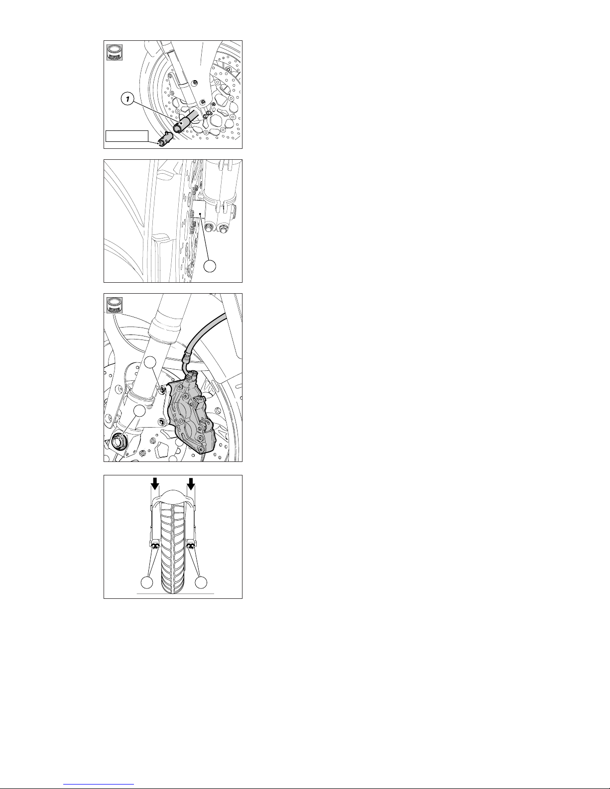
Mototelaio / Frame 87
3
4
55
0000.70139
RIMONTAGGIO RUOTA
ANTERIORE
Dopo aver eseguito tutte le
verifiche necessarie sulla ruota
procedere al rimontaggio nel modo
seguente:
▲
inserire la ruota completa tra i
gambali della forcella;
▲
lubrificare fusto e filetto del
perno ruota (1) con grasso
prescritto;
▲
inserire il perno ruota
assemblando lo stelo destro della
forcella con la ruota anteriore, senza
rinserirlo nello stelo sinistro;
▲
inserire il distanziale (2) tra il disco
freno sinistro e lo stelo forcella;
▲
montare l’attrezzo cod.
0000.70139 sul perno ruota;
▲
portare in battuta il perno sul
mozzo ruota;
▲
inserire l'attrezzo di
posizionamento perno nelle
apposite nicchie del piede forcella;
▲
ingrassare filetto e sottotesta del
dado di bloccaggio (3), quindi
avvitarlo sull’estremità del perno
ruota;
▲
bloccare il dado (3) alla coppia di
serraggio prescritta;
▲
rimontare le pinze serrando le viti
(4) di fissaggio alla coppia prescritta;
▲
controllare che i dischi scorrano
liberamente all’interno delle pinze;
▲
Prima di serrare le viti (5) mettere
a terra la moto e spingere sui
semimanubri per caricare le
sospensioni; in questo modo si
otterrà l'assestamento dei gambali
sul perno ruota
▲
Bloccare le viti (5) alla coppia
prescritta procedendo con sequenza
1-2-1.
REFITTING THE FRONT WHEEL
Overhaul and check the wheel. Refit
the wheel as follows:
▲
Insert the complete wheel
between the fork legs.
▲
Grease the wheel shaft (1) and its
thread with recommended grease.
▲
Fit the shaft into right-hand fork
leg and front wheel, do not insert it
into left fork leg.
▲
Insert spacer (2) between lefthand brake disc and fork leg.
▲
Fit service tool part no.
0000.70139 to the wheel shaft.
▲
Insert the shaft all the way into
the wheel hub.
▲
Insert the shaft locating tool into
the slots in the fork leg bottom end.
▲
Grease thread and underhead of
the shaft lock nut (3). Fit and tighten
the lock nut on the end of the wheel
shaft.
▲
Tighten the nut (3) to the
specified torque.
▲
Refit the calipers and tighten the
caliper retaining bolts (4) to the
specified torque.
▲
Check that the brake discs run
smoothly inside the calipers.
▲
Before tightening the pinch bolts
(5), take the bike off the stand and
press up and down on the
handlebars to load the suspension.
This will locate the fork legs
properly on the wheel shaft.
▲
Tighten the pinch bolts (5) to the
specified torque. Tighten in the
sequence 1-2-1.
2
B
B
Page 88
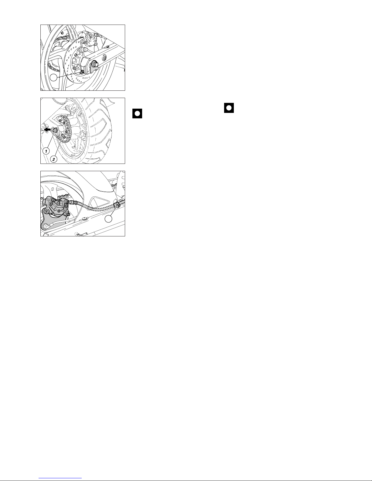
88 Mototelaio / Frame
REMOVING THE REAR WHEEL
❍
Place the bike on a suitable stand
so that the rear wheel is raised off
the ground.
❍
Unscrew the nut (1) on the LH
side of the swinging arm.
❍
Hold the caliper holder plate on
the right side and remove the wheel
shaft from the right side. If this
operation proves difficult, loosen
the chain tensioner bolts (2).
Caution
To prevent damage to the
brake caliper-master cylinder hose,
loosen the retaining screw (3) of the
hose clip on swinging arm and
remove the hose from the clip.
❍
Push the wheel forward and
remove the chain from the rear
sprocket. Remove the complete
rear wheel.
❍
Recover the spacer on the LH
side.
❍
Where necessary, overhaul the
wheel as described in “Wheel
overhaul”.
❍
Remove the sprocket flange from
the wheel hub and check the
condition of the cush drive rubbers.
SMONTAGGIO RUOTA
POSTERIORE
❍
Posizionare il veicolo su un adatto
supporto per poter avere la ruota
posteriore sollevata da terra.
❍
Svitare il dado (1) sul lato sinistro
del forcellone.
❍
Sfilare dalla parte opposta il perno
ruota e, contemporaneamente,
sostenere la piastra portapinza sul
lato destro. In caso di difficoltà
allentare le viti (2) dei tendicatena.
Importante
Per evitare danni alla
tubazione di collegamento pinzapompa, allentare la vite (3) che tiene
la staffetta di fissaggio del tubo al
forcellone. Sfilare il tubo dalla
staffetta.
❍
Spingere in avanti la ruota per
permettere alla catena di
scarrucolare dalla corona posteriore
e rimuovere la ruota completa.
❍
Recuperare il distanziale sul lato
sinistro.
❍
Procedere alle operazioni di
revisione necessarie come descritto
al paragrafo “Revisione ruote”.
❍
Verificare lo stato di usura dei
gommini parastrappi dopo aver
rimosso la flangia portacorona dal
mozzo ruota.
2
3
Page 89
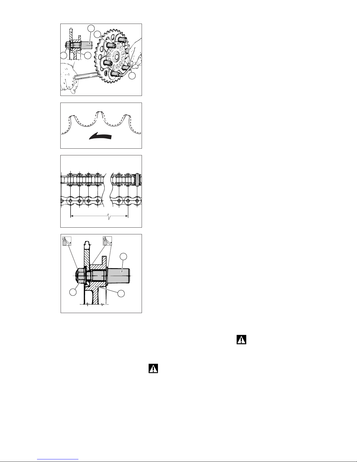
Mototelaio / Frame 89
CHANGING THE REAR
SPROCKET
To change the rear sprocket you
must first remove the complete rear
wheel from the bike following the
instructions given above in
“Removing the rear wheel”.
Proceed as follows:
❍
remove the complete sprocket
and flange assembly (1) from the
wheel;
❍
clamp the six pins (2) at the cush
drive rubbers with a hexagon
wrench and unscrew the six nuts (3)
holding the sprocket, the flange (1)
and the pins together;
❍
remove the rear sprocket from
the mount.
Inspection
The rear sprocket, the front sprocket
and the chain must all be changed
together.
Visually inspect the front and rear
sprockets to check the wear of the
final drive. If the tooth profile is as
shown by the continuous line in the
figure, change the sprockets.
To check chain wear, stretch the
chain and measure 16 links.
●
If the length (L) of 16 links is
longer than 256.5 mm, replace the
chain.
To change the front sprocket, see
“Removing the front sprocket”.
Reassembly
▲
Check that all the pins (2) are
securely fixed and tightened to the
flange (1). If the pins are loose,
unscrew left-threaded pins, clean
the threads and apply permanent
retaining compound to the larger
threads.
▲
Fit and tighten the pins to the
flange to the specified torque.
▲
Apply medium-strength
threadlocker to the threads on the
end of the pins (2).
▲
Fit the new sprocket, clamp the
pins and tighten the sprocket nuts
to the specified torque.
Warning
Follow the above procedure
closely. The pins must be fully
tightened before the sprocket is
fitted and tightened. If the pins are
not fully tightened before the
sprocket is fitted, the sprocket will
be incorrectly mounted. Loose
sprocket pins and an incorrectly
mounted sprocket will make the
bike dangerous to ride.
SOSTITUZIONE DELLA
CORONA
Per la sostituzione della corona è
necessario rimuovere la ruota
posteriore completa dal motociclo
nel modo descritto al paragrafo
“Smontaggio ruota posteriore”.
Procedere quindi nel modo
seguente:
❍
estrarre la corona completa di
flangia (1) di supporto;
❍
trattenere con chiave esagonale, i
sei perni (2), installati in
corrispondenza dei parastrappi in
gomma, e contemporaneamente,
svitare i sei dadi (3) che rendono
solidale corona, flangia (1) e perni (2).
❍
Separare la corona dal supporto.
Ispezione
La sostituzione della corona deve
avvenire unitamente al pignone
motore e alla catena.
Per verificare l’usura della
trasmissione secondaria è
necessario procedere al controllo
visivo del pignone e della corona. Se
il profilo dei denti risulta come in
figura (linea continua) procedere alla
sostituzione.
Nel caso della catena, occorre
misurare 16 passi mantenendola
ben tesa.
●
Se la quota (L) riscontrata risulta
superiore a 256,5 mm, sostituire la
catena.
Per la sostituzione del pignone
vedi paragrafo “Smontaggio
pignone catena”.
Rimontaggio
▲
Assicurarsi che tutti i perni (2)
risultino bloccati sulla flangia (1). Se
così non fosse è necessario svitare i
perni che hanno una filettatura
sinistra e, dopo aver pulito le
filettature, applicare bloccante
permanente sulla filettatura di
diametro maggiore.
▲
Serrarli sulla flangia alla coppia
prescritta.
▲
Applicare frenafiletti medio sul
filetto di estremità dei perni (2).
▲
Inserire la corona nuova e,
facendo reazione sui perni,
serrare i dadi di fissaggio alla
coppia prescritta.
Attenzione
Eseguire attentamente la
procedura illustrata.
Se il o i perni non sono avvitati
completamente sulla flangia,
prima del serraggio finale dei
dadi sulla corona, si otterrà un
montaggio errato con gravi
conseguenze per il motociclo e
a chi lo conduce.
1
3
2
13
2
2
1
1
a
1
st
2
a
2
nd
3
a
3
rd
4
a
4
th
15
a
15
th
L
16
a
16
th
2
LOCK
8
LOCK
Page 90

90 Mototelaio / Frame
LAVAGGIO DELLA CATENA
Il corretto lavaggio della catena con
O-rings deve essere effettuato con
petrolio, nafta, oppure olio di
paraffina.
È da evitare assolutamente l’utilizzo
di benzina, trielina e di solventi di
ogni tipo, che potrebbero
danneggiare gli O-rings in gomma.
Per questa ragione sono da evitare
anche i prodotti spray non specifici
per catene O-ring.
LUBRIFICAZIONE DELLA
CATENA
Nella catena con O-rings la
lubrificazione antiusura è assicurata
dal lubrificante primario sigillato,
nella zona di lavoro perno-bussola,
dagli stessi O-rings. È tuttavia
indispensabile provvedere ad una
lubrificazione periodica a scopo
protettivo sia delle parti metalliche
della catena che degli O-rings che
devono essere mantenuti morbidi
per garantire la massima tenuta.
La lubrificazione a scopo protettivo
si ottiene applicando, con un
semplice pennello, sull’intera
lunghezza della catena, sia
all’interno che all’esterno un velo di
olio motore ad alta densità, tipo SAE
10W-40.
WASHING THE CHAIN
Chains with O-rings must be
washed in oil, diesel fuel or paraffin
oil.
Do not use fuel, trichlorethylene or
other solvents which will damage
the rubber O-rings. Only use sprays
which specify that they are for use
with O-ring chains.
CHAIN LUBRICATION
Chains with O-rings have sealed,
permanent lubrication in the link
pins and bushes. This type of chain
must nevertheless be lubricated at
regular intervals to protect the metal
parts and to keep the O-rings soft
and pliable.
Using a brush, apply a thin
protective film of high density SAE
10W-40 engine oil along the entire
length of the chain, both on the
inboard and outboard side.
Page 91
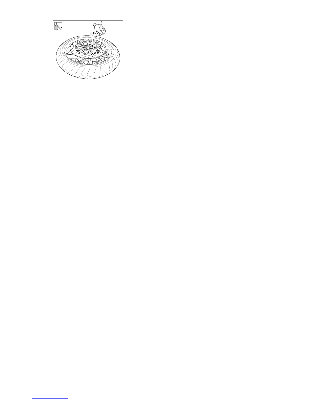
Mototelaio / Frame 91
2
LOCK
DISCHI FRENO
Il disco freno deve essere
perfettamente pulito, cioè senza
ruggine, olio, grasso od altra
sporcizia e non deve presentare
profonde rigature.
●
Spessore disco anteriore nuovo:
5±0,1 mm
●
Spessore disco al limite di usura:
4,5 mm
●
Spessore disco posteriore nuovo:
4±0,1 mm
●
Spessore disco al limite di usura:
3,6 mm
I dischi anteriori sono composti da
una parte solidale al cerchio ruota e
da una fascia frenante.
Dovendo sostituire il disco è
necessario sostituire entrambi i
componenti.
●
Nel caso del disco posteriore la
distorsione non deve superare i
0,3 mm (misura da rilevare con un
comparatore con disco montato sul
cerchio).
Per rimuovere il disco dal cerchio
ruota è necessario svitare le sei viti
di fissaggio.
▲
Quando si procede al rimontaggio
pulire perfettamente le superfici di
appoggio e avvitare le viti alla coppia
di serraggio prescritta, applicando
sul filetto frenafiletti medio.
BRAKE DISCS
Brake discs must be clean without
any signs of rust, oil, grease or dirt.
Brake discs must not be deeply
scored.
●
Thickness of new front brake
disc:
5±0.1 mm
●
Permitted minimum thickness
(wear limit) of front brake disc:
4.5 mm
●
Thickness of new rear brake disc:
4±0.1 mm
●
Permitted minimum thickness
(wear limit) of rear brake disc:
3.6 mm
Front brake discs consist of two
parts: an inner rotor fixed to the
wheel hub and an outer ring.
Both parts must be changed
together.
●
Distortion of the rear brake disc
must not exceed 0.3 mm. Check
distortion with the disc mounted on
the wheel; use a dial gauge.
To remove the disc from the wheel,
unscrew the six fixing bolts.
▲
At reassembly, thoroughly clean
the contact surfaces, apply mediumstrength threadlocker to the threads
and tighten the bolts to the
specified torque.
Page 92
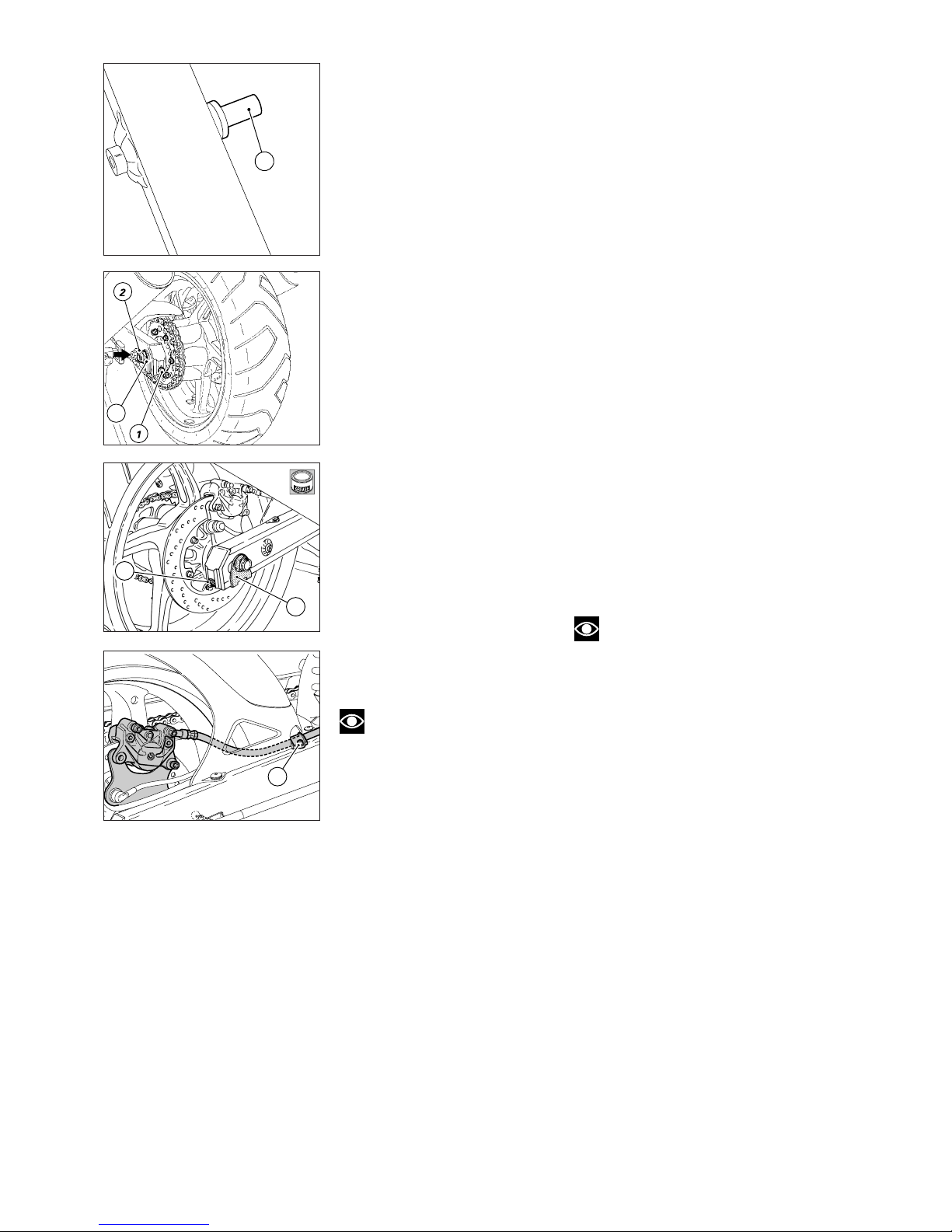
92 Mototelaio / Frame
4
5
RIMONTAGGIO RUOTA
POSTERIORE
Dopo aver eseguito tutte le
verifiche necessarie sulla ruota,
procedere al rimontaggio nel
modo seguente:
▲
distanziare leggermente le
pastiglie freno all’interno della pinza;
▲
introdurre la ruota completa
di flangia portacorona e di
piastra porta pinza nel forcellone,
ed inserire la catena sulla
corona;
▲
inserire l’asola della piastra
portapinza nell’apposito fermo (1)
sul forcellone;
▲
lubrificare perno e filetto con
grasso prescritto;
▲
montare la piastrina (2) ed infilare
il perno ruota dal lato destro; se
l’operazione risulta difficoltosa è
necessario allentare le viti (3) dei
tendicatena;
▲
montare l’altra piastrina (2) e il
dado (4) sul lato opposto;
▲
eseguire le operazioni di tensione
catena e di allineamento ruota come
descritto alla sezione “Registrazioni
e regolazioni”;
▲
verificare che il tubo freno
non risulti schiacciato o
eccessivamente piegato quindi
bloccare la vite (5).
▲
bloccare il dado (4) sul perno
ruota alla coppia prescritta;
▲
verificare che la sporgenza del
perno ruota dai dadi di bloccaggio
sia uguale su entrambi i lati;
▲
bloccare le viti (3) dei tendicatena
alla coppia prescritta.
Nota
Il traferro fra sensore e vite
fiss. disco freno post. deve essere
compreso 0,6÷2,2 mm
REFITTING THE REAR WHEEL
When you have completed all
checks and overhaul operations on
the rear wheel, refit the wheel as
follows:
▲
Push the brake pads apart into
the caliper.
▲
Fit the whole wheel – complete
with sprocket flange, caliper holder
plate - onto the swingarm, and run
the chain onto the sprocket.
▲
Insert the caliper holder plate slot
into the retainer (1) of the swingarm.
▲
Lubricate the wheel shaft and the
thread with the specified grease.
▲
Fit the plate (2) and fit the wheel
shaft from the RH side. If it proves
difficult, loosen the chain tensioner
bolts (3).
▲
Fit the other plate (2) and the
wheel nut (4) on the other side.
▲
Tension the chain and align the
wheel as described in the “Settings
and Adjustments” section.
▲
Check that the brake hose is not
squashed or bent. Tighten the
screw (5).
▲
Tighten the nut (4) on the wheel
shaft to the specified torque.
▲
Check that the wheel shaft thread
projects from the lock nuts by the
same amount on both ends.
▲
Tighten the chain tensioner bolts
(3) to the specified torque.
Note
Gap between sensor and rear
brake disc securing bolt must be
between 0.6-2.2 mm
3
2
B
1
Page 93
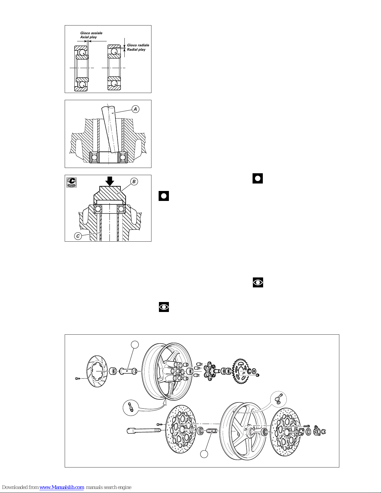
Mototelaio / Frame 93
WHEEL OVERHAUL
Bearings
Before proceeding to check wheel
dimensions, check the wear of the
wheel hub and sprocket flange
bearings. Check bearing wear by
hand with the bearing in its seats.
Clean and degrease the bearing
first.
❍
Turn the inner ring and push it in
and out to check the amount of
radial and axial play. Excessive play
will cause vibrations and make the
bike unstable. Badly worn bearings
must therefore be changed.
❍
To remove the bearing, use a
hammer and a drift (A). Apply
pressure on the inner ring only, until
the bearing comes out.
❍
Continually change the point of
pressure to keep the bearing square
during removal.
Caution
Do not refit bearings once
they have been removed.
▲
Before you fit new bearings,
check that the seat is clean and free
from scoring and damage.
▲
Grease the bearing seat and then
push the bearing into the seat.
▲
Using a tubular drift (B) which
only exerts pressure on the outer
bearing ring, drive the bearing fully
into its seat.
▲
Ensure that you fit the spacer (C)
between the two wheel hub
bearings.
Note
Wheels must be re-balanced
after repair, maintenance and
overhaul operations.
REVISIONE RUOTA
Cuscinetti
Prima di effettuare controlli
dimensionali è necessario
assicurarsi dello stato di usura dei
cuscinetti del mozzo ruota e della
flangia portacorona; questa verifica
deve essere fatta manualmente
dopo aver pulito e sgrassato il
cuscinetto nella sua sede.
❍
Ruotare l’anello interno e
spingerlo in dentro e in fuori per
verificare l’entità del gioco radiale e
assiale; un gioco eccessivo può
essere causa di vibrazioni e instabilità
del mezzo ed è necessario
procedere alla sostituzione.
❍
Utilizzare un martello e un perno
(A) con il quale si deve fare pressione
solo sull’anello interno del cuscinetto
fino ad ottenere l’estrazione.
❍
Spostare continuamente il
punto di pressione in modo da
ottenere un’estrazione il più
possibile lineare.
Importante
I cuscinetti rimossi non
devono essere rimontati.
▲
Quando si rimontano i cuscinetti
nuovi controllare la sede, deve
essere pulita ed esente da solchi o
graffiature.
▲
Ungere la sede prima di rimontare
il cuscinetto quindi spingerlo in sede.
▲
Utilizzare un tampone tubolare (B)
con il quale fare pressione solo
sull’anello esterno del cuscinetto
fino alla sua completa introduzione.
▲
Fare attenzione che tra i due
cuscinetti del mozzo ruota sia stato
inserito il distanziale (C).
Note
Dopo ogni intervento sulla
ruota è consigliabile provvedere alla
sua equilibratura.
C
C
;;
;;
;;
;;
@@
@@
@@
@@
;;
;;
;;
;;
@@
@@
@@
@@
;;
;;
;;
;;
yy
yy
yy
yy
;;
;;
;;
@@
@@
@@
;;
;;
;;
@@
@@
@@
;;
;;
;;
yy
yy
yy
;;;;
;;;;
;;;;
;;;;
;;;;
@@@@
@@@@
@@@@
@@@@
@@@@
;;;;
;;;;
;;;;
;;;;
;;;;
@@@@
@@@@
@@@@
@@@@
@@@@
;;;;
;;;;
;;;;
;;;;
;;;;
;;;;
;;;;
;;;;
;;;;
;;;;
@@@@
@@@@
@@@@
@@@@
@@@@
;;;;
;;;;
;;;;
;;;;
;;;;
@@@@
@@@@
@@@@
@@@@
@@@@
;;;;
;;;;
;;;;
;;;;
;;;;
A
;;;;
;;;;
@@@@
@@@@
;;;;
;;;;
@@@@
@@@@
;;;;
;;;;
;;
;;
;;
@@
@@
@@
;;
;;
;;
@@
@@
@@
;;
;;
;;
;;;
;;;
;;;
@@@
@@@
@@@
;;;
;;;
;;;
@@@
@@@
@@@
;;;
;;;
;;;
;@;@;
y
;@;@;
y
B
C
Gioco assiale
Axial play
Jeu axial
Achsenspiel
Juego axial
;;;
;;;
@@@
@@@
;;;
;;;
@@@
@@@
;;;
;;;
yyy
yyy
;;;
;;;
@@@
@@@
;;;
;;;
@@@
@@@
;;;
;;;
yyy
yyy
Gioco radiale
Radial play
Jeu radial
Radialspiel
Juego radial
C
Page 94
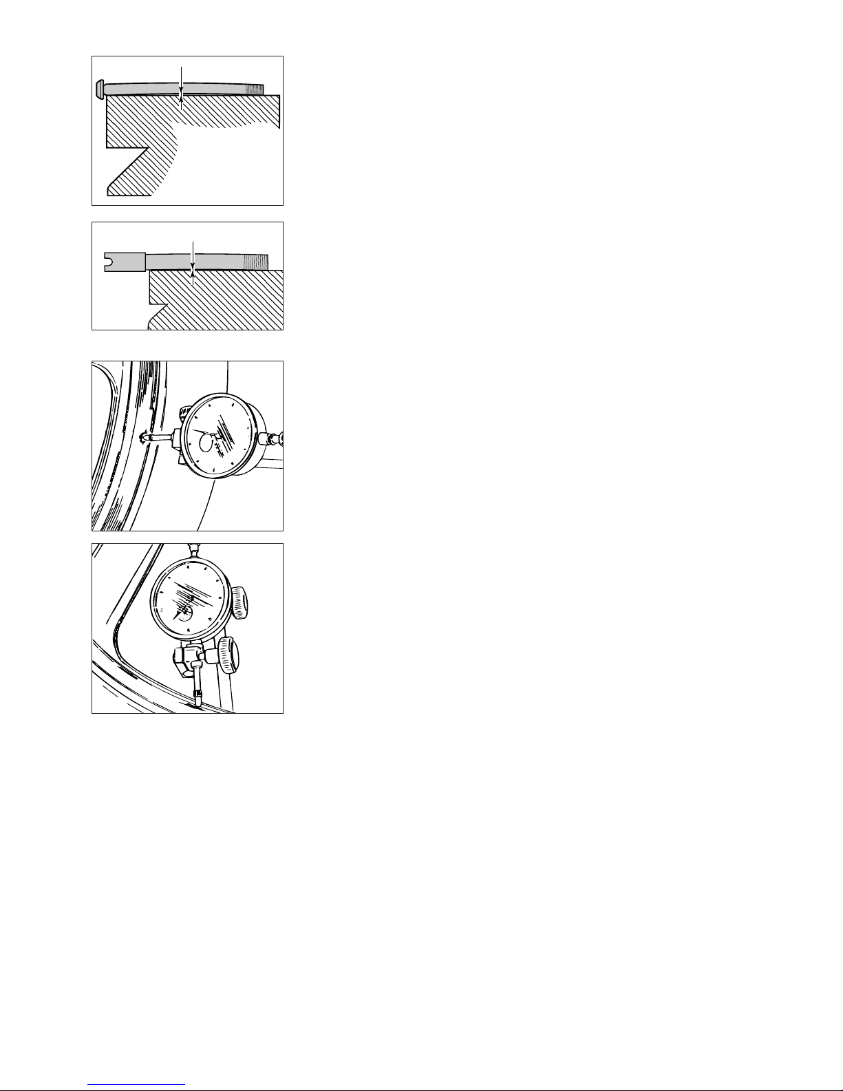
94 Mototelaio / Frame
Perno ruota
Verificare l’entità della distorsione
del perno ruota anteriore e
posteriore:
ruotare su di un piano di riscontro il
perno e controllare con uno
spessimetro il valore massimo della
distorsione;
●
limite di servizio su 100 mm:
0,2 mm.
Cerchio
Una volta accertato il buono stato
dei cuscinetti è necessario eseguire
la verifica del cerchio operando nel
modo seguente:
❍
effettuare un controllo visivo per
individuare eventuali deformazioni,
solchi o crepe: in caso affermativo
sostituire il cerchio;
❍
inserire il perno nella ruota e
posizionarlo su due riscontri
fissi;
❍
installare un comparatore
supportandolo in modo da poter
rilevare i valori di sbandamento
laterale ed eccentricità del cerchio
ruota rispetto all’asse del perno.
Valori standard:
●
sbandamento laterale:
0,5 mm
●
eccentricità:
0,8 mm
●
limite di servizio:
2 mm
Se i valori riscontrati non rientrano
nel limite è necessario sostituire il
cerchio.
Wheel shaft
Check the distortion of the front and
rear wheel shafts.
Roll the shaft on a reference surface
and check the maximum distortion
using a feeler gauge.
●
Service limit on 100 mm:
0.2 mm
Rims
After you have checked the
bearings, check the rims as follows:
❍
Inspect the rim for cracks, scoring
and deformation; change damaged
rims;
❍
Insert the wheel shaft in the
wheel and mount the wheel on two
fixed reference blocks;
❍
Using a dial gauge, measure the
rim run-out and out-of-round with
respect to shaft axis.
Standard values
●
Run-out:
0.5 mm
●
Out-of round:
0.8 mm
●
Service limit:
2 mm
If the values measured are not
within these limits, change the rim.
Page 95
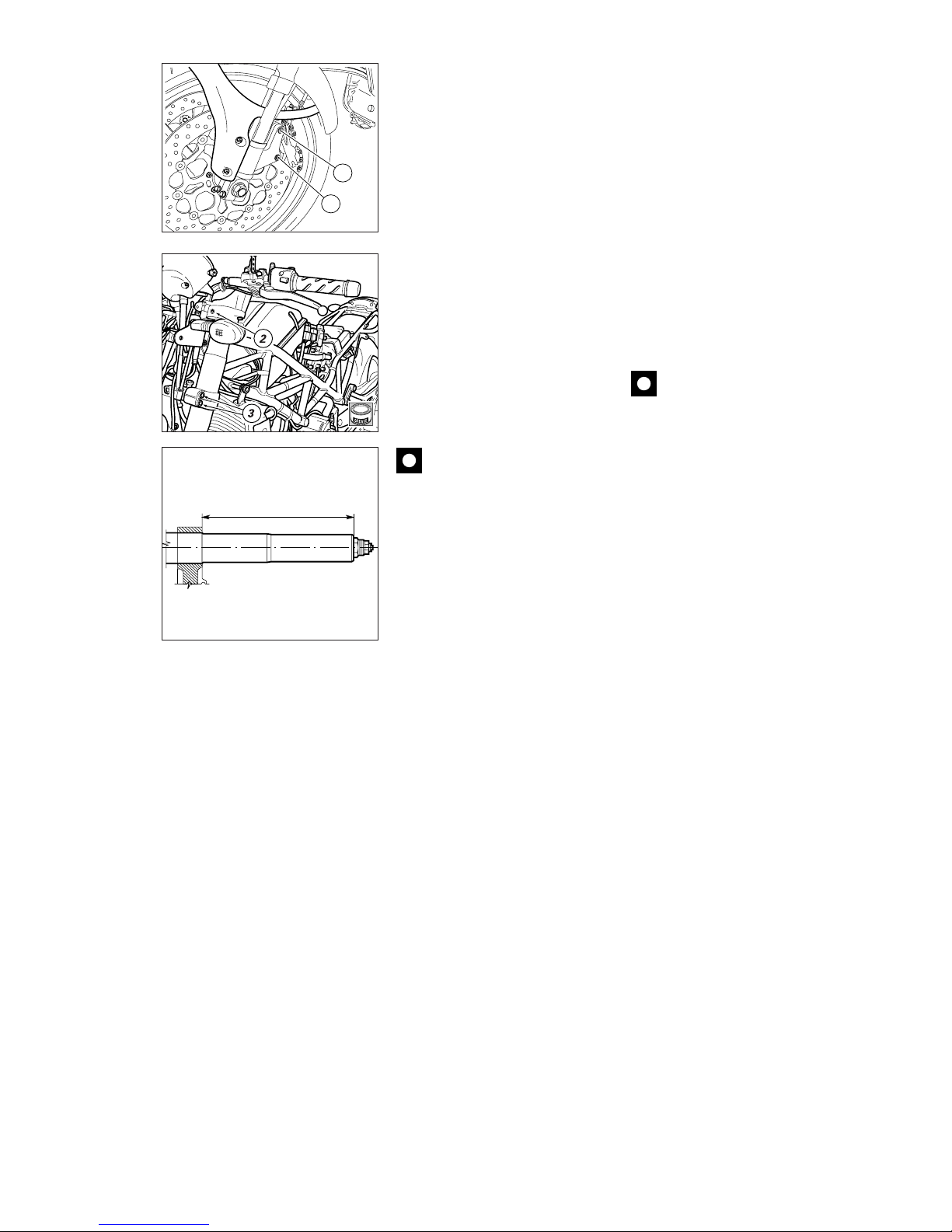
Mototelaio / Frame 95
REMOVING THE FRONT FORK
❍
Unscrew the four screws (1) and
remove the front mudguard.
❍
Remove the front wheel and the
headlight fairing as described
previously.
❍
Loosen the pinch bolts (2) holding
the fork legs to the steering head.
❍
Loosen the pinch bolts (3) holding
the fork legs to the bottom yoke.
❍
Slide the legs out downwards.
Overhaul where necessary.
▲
At reassembly, insert the legs in
the bottom yoke and fix at the
measurement shown in the figure.
▲
Tighten the leg pinch bolts on the
steering head and bottom yoke to
the specified torque values.
Caution
If the pinch bolts (2) and (3) are
removed during disassembly,
grease their threads before refitting
and tightening.
▲
Refit all the parts removed during
disassembly.
195,5 (0 ÷ 1) mm
B
1
1
SMONTAGGIO FORCELLA
ANTERIORE
❍
Rimuovere il parafango anteriore
svitando le 4 viti (1).
❍
Rimuovere la ruota anteriore e il
cupolino come descritto ai paragrafi
precedenti.
❍
Allentare le viti (2) di fissaggio
degli steli forcella alla testa di
sterzo.
❍
Allentare le viti (3) di fissaggio
degli steli forcella alla base di
sterzo.
❍
Sfilare verso il basso gli steli ed
effettuare tutte le operazioni di
revisione necessarie.
▲
Quando si procede al rimontaggio
è necessario posizionare gli steli,
rispetto alla base di sterzo, facendo
riferimento alla quota di figura.
▲
Bloccare alla coppia di serraggio
prescritta le viti di fissaggio degli
steli alla base e alla testa di sterzo.
Importante
Se durante lo smontaggio sono
state rimosse dalla loro sede
applicare grasso prescritto sul filetto
delle viti (2) e (3) prima del bloccaggio.
▲
Riassemblare tutte le parti
rimosse durante lo smontaggio.
Page 96
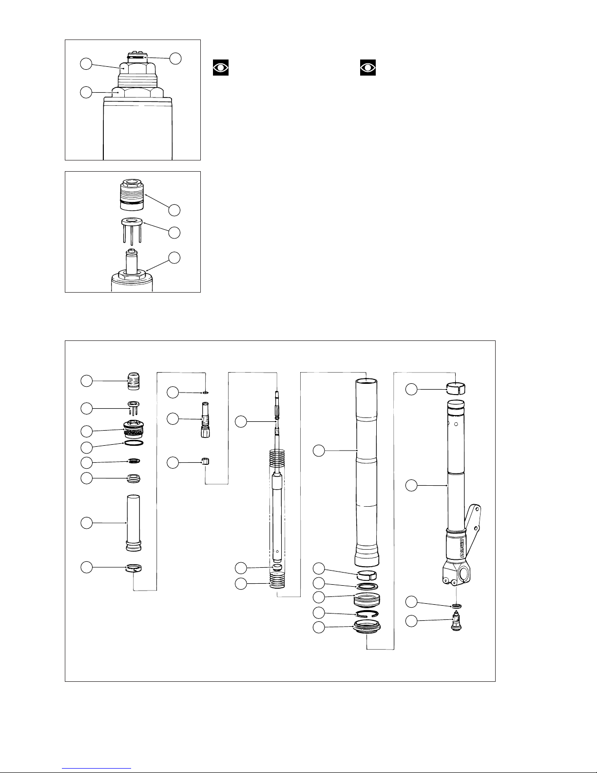
96 Mototelaio / Frame
22
23
24
14
21
20
19
18
17
16
13
15
12
1
10
11
9
8
7
6
5
4
3
2
1
2
4
2
3
4
REVISIONE FORCELLA
Note
Gli attrezzi specifici per
effettuare la revisione della
forcella, sono riportati all’inizio del
capitolo.
I numeri riportati sulle figure di
questo paragrafo, si riferiscono ai
particolari della vista esplosa.
Pulire accuratamente gli steli prima
dello smontaggio.
Il registro dell’estensione deve
essere nella posizione minima.
Smontaggio
❍
Rimuovere l’anello di fermo (1).
❍
Svitare e rimuovere dal tappo la
vite di registro molla (2) e il piattello
(3).
❍
Svitare il tappo superiore (4).
FRONT FORK OVERHAUL
Note
The special service tools
required for this operation are listed
at the beginning of this section.
The reference numbers, which
appear in the instructions below,
refer to the numbered parts on the
exploded drawing.
Thoroughly clean the legs before
disassembly.
Turn the rebound adjuster to its
min. damping position.
Disassembly
❍
Remove the circlip (1).
❍
Unscrew and remove the spring
adjuster (2) and the plate (3) from
the plug.
❍
Unscrew the upper plug (4).
Page 97
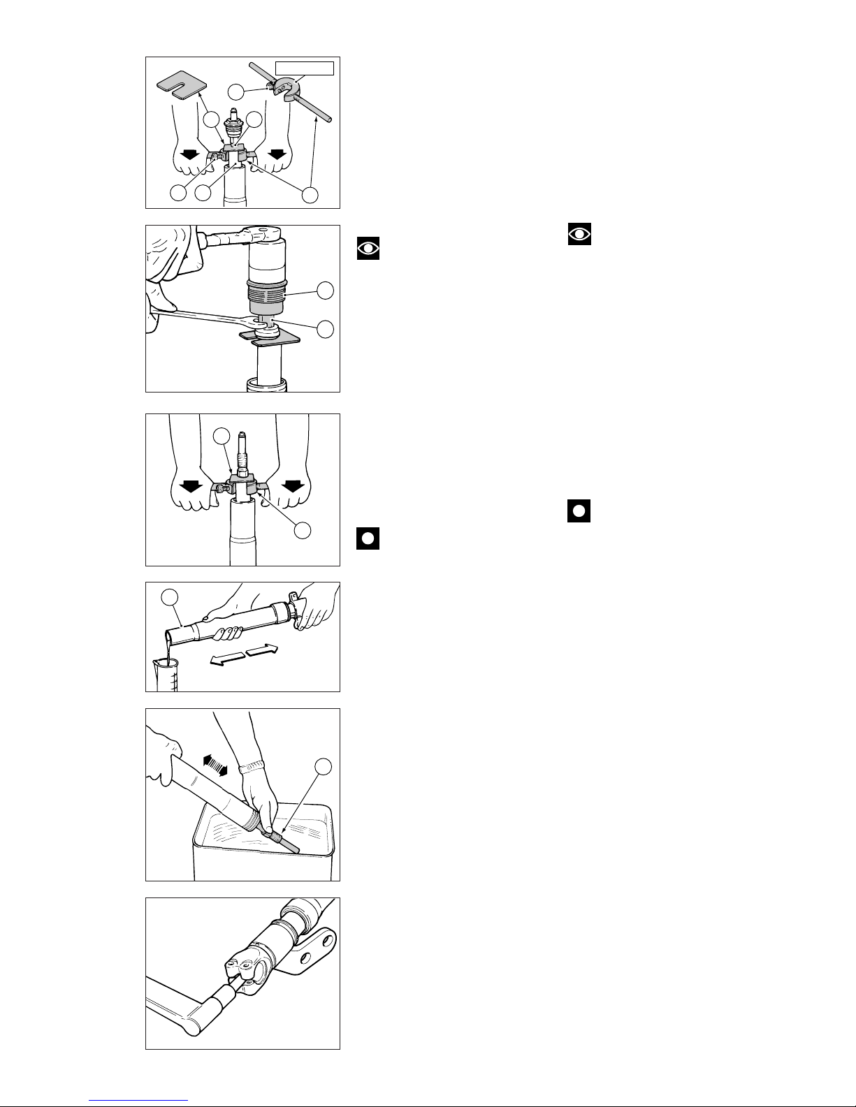
Mototelaio / Frame 97
4
10
A
8
C 11
B
B
88713.0967
A
B
16
12
❍
Montare l’attrezzo speciale (A,
cod. 88713.0967) bloccandolo con
la vite (B) nel foro laterale del collare
molla (8).
❍
Spingere l’attrezzo verso il basso
per comprimere la molla e quindi
installare il distanziale (C)
dell’attrezzo sotto il controdado (11).
❍
Bloccare il registro
dell’estensione (10) con una chiave
esagonale e svitare il tappo
superiore (4) completo.
Note
Bloccare il registro (10) e
non il controdado (11) per svitare
il tappo (4).
❍
Rimuovere il distanziale (C)
spingendo verso il basso l’attrezzo (A).
❍
Rimuovere dall’asta: il
collare molla (8) con rondella (6)
e cursore (7) e la molla (13).
❍
Scaricare l’olio dall’interno dello
stelo pompando 8÷10 volte con il
fodero esterno (16) e con l’asta
ammortizzatore (12) come in
figura.
❍
Posizionare il supporto asse ruota
in una morsa provvista di ganasce di
protezione.
❍
Svitare la vite di registro (25) della
compressione.
Importante
Se l’operazione risulta
difficoltosa, rimontare
provvisoriamente i componenti
precedentemente rimossi
(13), (8), (7), (6) e (4) e contrastare
con il tappo superiore.
❍
Fit the special tool (A part no.
88713.0967) and lock it with the
screw (B) in the side hole of the
spring collar (8).
❍
Push the tool down to compress
the spring. Fit the tool spacer (C)
under the lock nut (11).
❍
Hold the rebound adjuster (10) in
place with a hex. wrench and
unscrew the complete upper plug
(4).
Note
When unscrewing the upper
plug (4), hold the adjuster (10) and
not the lock nut (11).
❍
Push the tool (A) downwards and
remove the spacer (C).
❍
Remove the following parts from
the rod: the spring collar (8)
complete with washer (6) and ring
(7) and the spring (13).
❍
Drain the used oil from inside the
fork leg, pump the slider (16) and
the damper rod (12) up and down 8
to 10 times as shown in the figure.
❍
Clamp the wheel shaft support in
a vice with suitable protection jaws.
❍
Unscrew the compression
adjuster (25).
Caution
If this operation proves
difficult, temporarily refit the
removed parts (13), (8), (7), (6) and (4)
and counteract with the upper plug.
Page 98
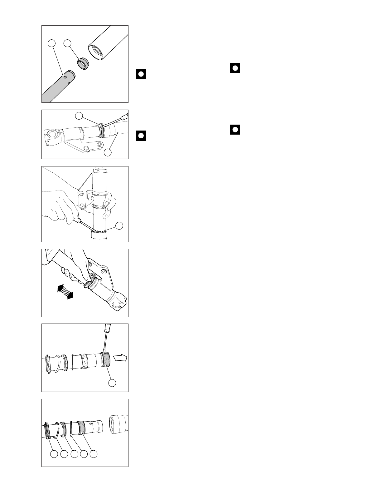
98 Mototelaio / Frame
1512
16
21
20
22
21 20 19 18 17
❍
Rimuovere la vite di registro
compressione (25) e la
guarnizione (24).
❍
Sfilare la cartuccia ammortizzatore
(12) completa e rimuovere la
boccola di centraggio inferiore (15).
Importante
Non aprire la cartuccia
ammortizzatore.
❍
Sfilare il raschiapolvere (21) dalla
sommità del fodero esterno (16)
facendo leva con un cacciavite.
❍
Rimuovere l’anello di fermo (20)
dal fodero esterno.
Importante
Fare attenzione a non rovinare
il tubo portante (23) e la sede nel
tubo esterno.
❍
Estrarre il fodero esterno dal tubo
portante tirando con forza,
assestando colpi in rapida
successione, per contrastare la
resistenza della boccola di guida
(17) forzata sul fodero.
❍
Rimuovere la boccola (22) dal
tubo portante inserendo la punta di
un cacciavite nell’apertura della
boccola stessa.
❍
Rimuovere dal tubo portante:
la boccola di guida (17);
lo scodellino (18);
l’anello di tenuta (19);
l’anello di fermo (20);
il raschiapolvere (21).
❍
Remove the compression
adjuster (25) and the seal (24).
❍
Slide out the complete damper
cartridge (12) and remove the lower
centering bush (15).
Caution
Do not open the damper
cartridge.
❍
Remove the dust seal (21) from
the slider top (16) with a
screwdriver.
❍
Remove the circlip (20) from the
slider.
Caution
Make sure not to damage the
stanchion tube (23) and the slider
seat.
❍
Pull strongly and tap to remove
the slider from the stanchion tube.
Tap rapidly to counteract the pilot
bushing (17) forced into the slider.
❍
Insert the bit of a screwdriver into
the bush opening and remove the
bush (22) from the stanchion tube.
❍
Remove the following parts from
the stanchion tube:
pilot bushing (17);
retainer (18);
oil seal (19);
circlip (20);
dust seal (21).
Page 99
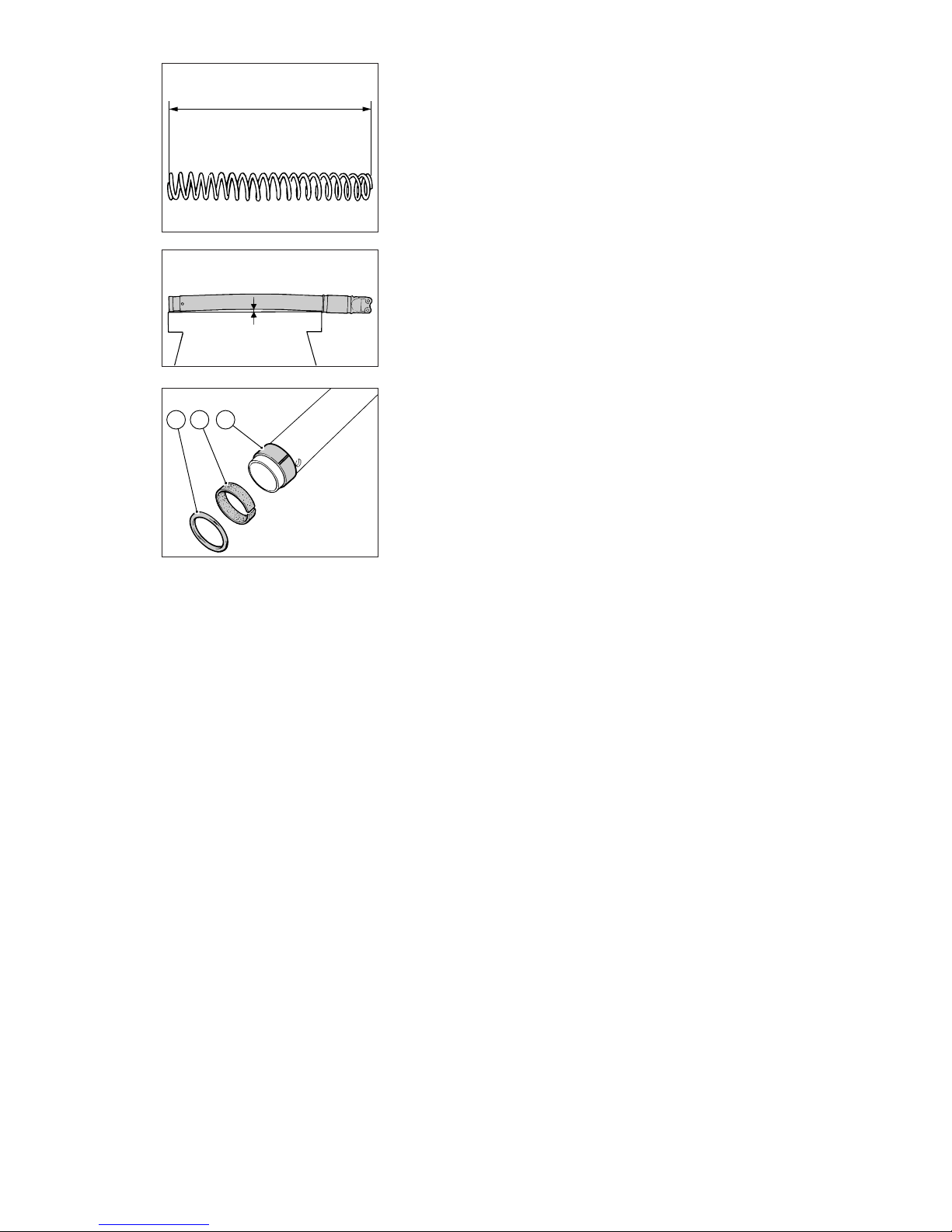
Mototelaio / Frame 99
L
221718
Ispezione
Appoggiare su di un piano la
molla e misurarne la lunghezza
libera (L).
●
Limite di servizio:
270 mm
Sostituire la molla se la lunghezza
non rientra nel limite.
❍
Esaminare la superficie esterna
dei due tubi portanti e quella
interna dei due foderi; non
dovranno apparire rigature,
scalini o punti di forzature.
❍
Controllare che ciascun tubo
portante scorra liberamente
all’interno del proprio fodero, ma
senza presentare eccessivo gioco.
●
Verificare la rettilineità dei tubi
portanti: massimo errore ammesso
0,10 mm.
❍
Verificare le condizioni delle
boccole (17) e (22): non devono
presentare solchi o scalinature e
non deve essere visibile il rame di
supporto sul lato in entrata. In caso
affermativo sostituire la boccola.
❍
Verificare la planarità dello
scodellino (18) appoggiandolo su di
un piano di riscontro: se risulta
distorto; sostituirlo.
Inspection
Place the spring on a flat surface
and measure its length when not
under compression (L).
●
Service limit:
270 mm
If the value measured is not within
this limit, change the spring.
❍
Examine the outer surface of the
two stanchions and the inner
surfaces of the two sliders. They
should be free of scoring, notches
or signs of forcing.
❍
Check that each stanchion slides
smoothly inside the sliders and that
there is not excessive play.
●
Ensure that the stanchions are
perfectly straight. Max. deviation
allowed: 0.10 mm
❍
Check that the bushes (17) and
(22) are free of scoring and notches.
The copper on the bush inlet side
should not be visible. If this is not
the case, change the bush.
❍
Ensure that the retainer (18) is not
bent. Put it onto a proper surface. If
it is bent, change the retainer.
Page 100
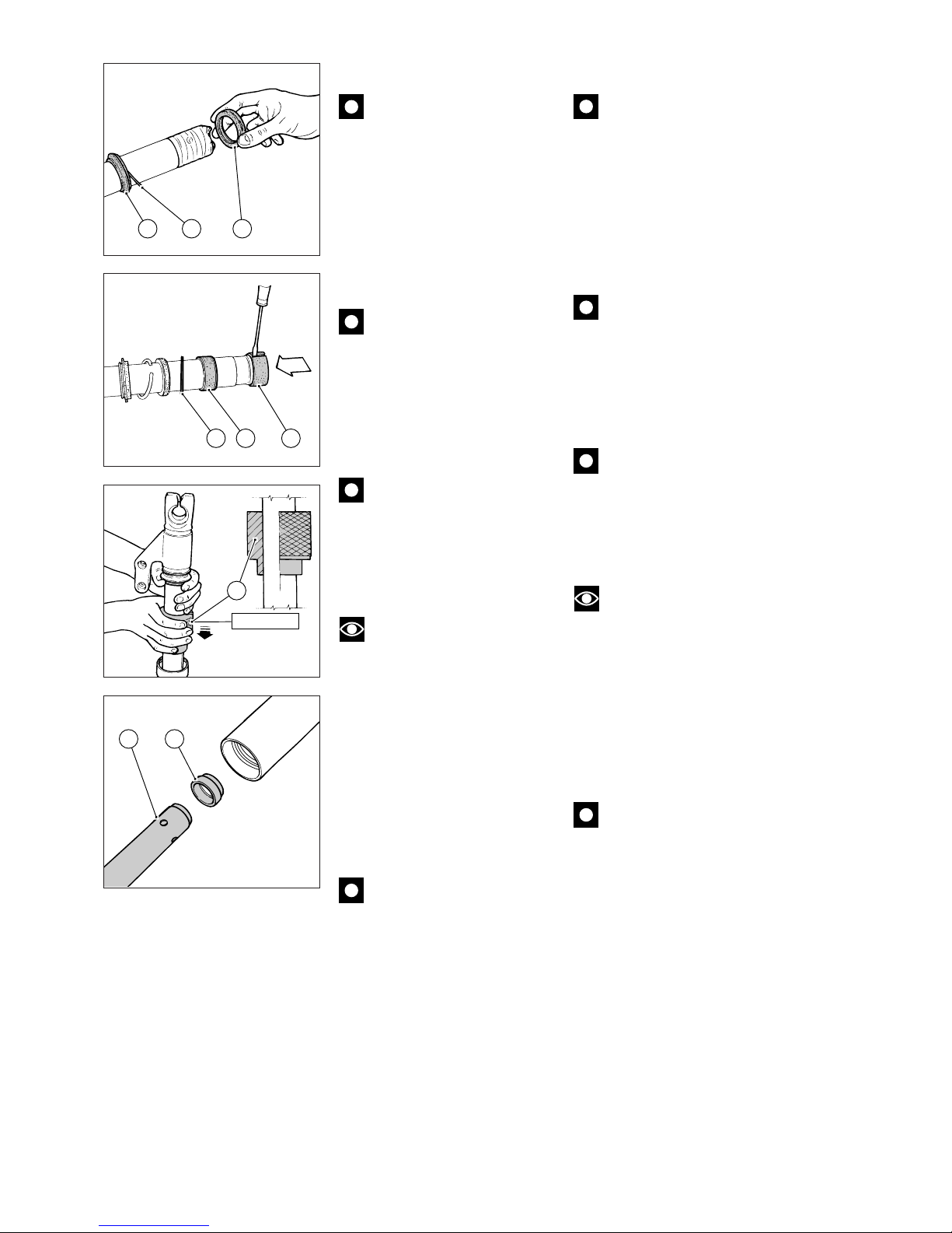
100 Mototelaio / Frame
Reassembly
Caution
Lubricate the sliding edges
with fork oil or seal grease before
reassembling the oil seal (19).
▲
Put some adhesive tape onto the
stanchion top.
▲
Fit the following parts into the
stanchion:
dust seal (21)
circlip (20)
oil seal (19).
Caution
Fit the oil seal with the
marked surface facing the dust seal.
▲
Fit the following parts into the
stanchion:
retainer (18);
pilot bushing (17);
stanchion bush (22).
Caution
Remove any burrs and make
sure not to damage the bush outer
coating.
▲
To make the next operation
easier, tape dust seal and circlip
together.
Note
Lubricate the bush sliding
surfaces with fork oil before
reassembling.
▲
Push the pilot bushing (17) and
the retainer (18) into the slider with
the seal ring tool (D, part no.
88713.0960).
▲
Push the oil seal (19) into the
slider using the above tool.
▲
Fit the circlip (20) and the dust
seal (21).
Caution
Ensure that the slider slides
smoothly along the stanchion tube.
Hold both stanchions and sliders in
your hands not to damage oil seals
and pilot bushings.
▲
Vice the wheel shaft support.
▲
Fit the lower centering bush (15)
into the damper cartridge end (12)
and then fit them into the stanchion
tube.
Rimontaggio
Importante
Prima di installare l’anello di
tenuta (19), lubrificare i bordi di
scorrimento con olio forcella o con
grasso per tenute.
▲
Proteggere l’estremità del tubo
portante con nastro.
▲
Installare i seguenti componenti
nel tubo portante:
raschiapolvere (21);
anello di fermo (20);
anello di tenuta (19).
Importante
Installare l’anello di tenuta con
la superficie marcata rivolta verso il
raschiapolvere.
▲
Installare i seguenti componenti
sul tubo portante:
scodellino (18);
boccola di guida (17);
boccola (22) del tubo portante.
Importante
Eliminare eventuali bave e
fare attenzione a non rovinare il
rivestimento esterno della boccola.
▲
Nastrare insieme il raschiapolvere
e l’anello di fermo che potrebbero
intralciare le operazioni successive.
Note
Prima di assemblare le due
parti, lubrificare le superfici di
scorrimento delle boccole con olio
forcella.
▲
Spingere la boccola di guida (17)
e lo scodellino (18) nel fodero
esterno utilizzando l’attrezzo premi
anello di tenuta (D, cod.
88713.0960).
▲
Spingere l’anello di tenuta (19)
nel fodero utilizzando la stessa
attrezzatura.
▲
Installare l’anello di fermo (20) e il
raschiapolvere (21).
Importante
Il fodero esterno deve
scorrere liberamente sul tubo
portante. Supportare
esclusivamente con le mani i tubi
portanti e i foderi esterni per non
danneggiare gli anelli di tenuta e le
boccole di guida.
▲
Bloccare il supporto asse ruota in
morsa.
▲
Installare la boccola di centraggio
inferiore (15) all’estremità della
cartuccia ammortizzatore (12) e
inserirli nel tubo portante.
88713.0960
D
12 15
21 20 19
221718
 Loading...