

Page 1
Page 2

Owner’s manual
ENGLISH
1
Page 3

This manual forms an integral part of the motorcycle and must be kept with it its whole service life.
If the motorcycle is resold, the manual must always be handed over to the new owner.
This manual must be preserved with care. If it lost or becomes damaged, contact a Ducati Dealer or authorised
Service Centre without delay to obtain a new copy of the manual.
The quality standards and safety of Ducati motorcycles are steadily improved as new design solutions,
equipment and accessories are developed. While the information contained in this manual is current at the
time of going to print, Ducati Motor Holding S.p.A. reserves the right to make changes at any time without
notice and without any obligations. For this reason, the illustrations in this manual might differ from your
motorcycle.
Any and all reproduction or spreading of the contents herein in whole or in part is forbidden. All rights reserved
to Ducati Motor Holding S.p.A. Any request for written authorisation to do so shall be addressed to this
company, specifying the reasons for request.
Enjoy your ride!
2
Page 4

Table of contents
Foreword 7
Safety guidelines 7
Safety alerts 8
Permitted use 9
Rider's obligations 9
Rider training 10
Riding gear 10
Best practices for motorcycle safety 12
Refuelling 14
Carrying the maximum load allowed 15
Information about carrying capacity 15
Dangerous products - warnings 16
Vehicle identification number 18
Engine identification number 19
Instrument panel (Dashboard) 20
Display settings and functions 20
Technological Dictionary 23
Function push-buttons 25
LCD - Main functions 26
LCD - Parameter setting/display 27
Vehicle speed indicator 29
Engine rpm indicator (RPM) 30
Menu 1 functions 31
Menu 1 functions: Odometer (TOT) 32
Menu 1 functions: Trip meter (TRIP 1) 33
Menu 1 functions: Trip meter (TRIP 2) 34
Menu 1 functions: Partial fuel reserve counter (TRIP
FUEL) 35
Menu 1 functions: Average fuel consumption
indicator (CONS. AVG) 36
Menu 1 functions: Instantaneous fuel consumption
indicator (CONS.) 37
Menu 1 functions: Average speed indicator (SPEED
AVG) 38
Menu 1 functions: Trip time indicator (TIME
TRIP) 39
Menu 2 functions 40
Menu 2 functions: Coolant temperature 41
Menu 2 functions: Air temperature (AIR) 43
Menu 2 functions: Clock 44
SET UP - Riding Style set indication 45
3
Page 5

SERVICE function - Maintenance
interventions 46
Active / not active ERRORS indication 49
Indication if the "LAP" function is active/not
active 50
Riding Mode SET UP function (riding style
change) 51
Error display function (ERRORS) 54
SETTING MENU 59
Customising Riding Modes (R.MODE) 61
DTC set up 65
ABS set up 71
ENGINE set up 75
ALL DEFAULT (Resetting the default parameters of
all Riding Modes) 77
DEFAULT (Resetting the default parameters of a
single Riding Mode) 79
Dashboard backlighting setting function
(B.LIGHT) 81
Lap time function (LAP): LAP activation/
deactivation 83
Lap time function (LAP): LAP registration 85
LAP time function: Stored LAPs displaying 87
Clock setting function (CLOCK) 91
Battery voltage function (BATTERY) 93
Engine rpm digital indication (RPM) 94
Immobilizer code (PIN CODE) 95
The Immobilizer system 103
Keys 104
Entering PIN CODE function for vehicle
release 105
Operation 108
Duplicate keys 109
Light control 110
Units of measurement modification function
(UNITS) 113
Other functions 123
Controls 125
Position of motorcycle controls 125
Ignition switch and steering lock 126
Left-hand switch 127
Clutch lever 128
Right-hand switch 131
Throttle twistgrip 132
Front brake lever 133
Rear brake pedal 134
Gear change pedal 135
Adjusting the position of the gearchange and rear
brake pedals 136
4
Page 6

Main components and devices 138
Position on the vehicle 138
Tank filler plug 139
Seat lock 140
Helmet cable 142
Side stand 144
Power socket 145
Central stand 146
Side pannier fitting 148
Side pannier use 149
Adjusting the rear shock absorber 155
Riding the motorcycle 157
Running-in recommendations 157
Pre-ride checks 159
ABS device 161
Starting the motorcycle 162
Moving off 164
Braking 165
Stopping the motorcycle 167
Parking 168
Refuelling 169
Tool kit and accessories 170
Main maintenance operations 171
Check and top up the coolant level 171
Checking brake and clutch fluid level 172
Check brake pads for wear 174
Charge the battery 175
Check drive chain tension 179
Chain lubrication 181
Replace the headlight bulbs 182
Replace the turn indicator bulbs 185
Number plate light 186
Beam setting 187
Adjust rear-view mirrors 189
Tubeless tyres 190
Check engine oil level 192
Clean and replace the spark plugs 194
Clean the motorcycle 195
Storing the motorcycle 196
Important notes 196
Scheduled maintenance chart 197
Scheduled maintenance chart: operations to be
performed by the Dealer 197
Scheduled maintenance chart: operations to be
performed by the customer 200
5
Page 7

Technical data 201
Weights 201
Overall dimensions 202
Top-ups 203
Engine 205
Timing system 206
Performance data 207
Spark plugs 207
Fuel system 207
Brakes 207
Transmission 208
Frame 209
Wheels 209
Tyres 209
Suspensions 209
Exhaust system 210
Available colours 210
Electrical system 211
Routine maintenance record 217
Routine maintenance record 217
6
Page 8

Foreword
Safety guidelines
We would like to welcome you among Ducati
enthusiasts, and congratulate you on your excellent
choice of motorcycle. We think you will ride your
Ducati motorcycle for long journeys as well as short
daily trips. Ducati Motor Holding S.p.A. wishes you
smooth and enjoyable riding.
Your motorcycle is the result of Ducati Motor Holding
S.p.A.'s on-going research and development efforts.
It is important that you preserve its quality standard
by strictly observing the maintenance plan and using
genuine spare parts. This manual provides
instructions on minor maintenance operations. Major
maintenance operations are described in the Service
Manual available to Ducati Authorised Service
Centres.
In your own interest, for your safety and in order to
guarantee product reliability, you are strongly advised
to refer to our authorised Dealers and Service Centres
for any operations listed in the scheduled
maintenance chart, see page 197.
Our highly skilled staff have access to special
implements and appropriate equipment required to
perform any servicing job at best, and use Ducati
original spare parts only as the best guarantee for full
interchangeability, smooth running and long life.
All Ducati motorcycles come with a Warranty Card.
The warranty does not apply to motorcycles used in
racing competitions.
Tampering with or altering any components, even
partially, will make the warranty null and void
effective immediately. Improper or poor
maintenance, using other than original spare parts or
parts not expressly approved by Ducati may invalidate
your warranty rights and lead to damage or loss of
performance.
Your safety and that of other road users are very
important. Ducati Motor Holding S.p.A. recommends
that you ride responsibly.
Before using your motorcycle for the first time, read
this entire manual carefully and closely follow the
guidelines outlined in it. The manual provides full
information on proper motorcycle operation and
7
Page 9

maintenance. In case of any doubts, please call a
Dealer or Authorised Service Centre.
Safety alerts
To alert you to potential hazards that could potentially
harm you or other persons, the following safety alerts
have been used:
- Safety labels on motorcycle;
- Safety messages preceded by a warning symbol
and the word WARNING or IMPORTANT.
Warning
Failure to comply with these instructions may
put you at risk and result in severe injury to rider or
other persons or even death.
Important
Possibility of damaging the motorcycle and/or
its components.
Note
Additional information concerning the job being
carried out.
The terms RIGHT and LEFT refer to the motorcycle
viewed from the riding position.
8
Page 10

Permitted use
This motorcycle may be used for riding on dirt trails
or for off-road riding.
Warning
This motorcycle may not be used to tow any
trailers or with a side-car attached; this can lead to
loss of control and result in an accident.
This motorcycle carries the rider and can carry a
passenger.
Warning
The total weight of the motorcycle in running
order including rider, passenger, luggage and
additional accessories should not exceed 406 kg/895
lb.
Rider's obligations
All riders must hold a valid licence.
Warning
Riding without a licence is illegal and is
prosecuted by law. Always make sure you have your
licence with you when riding. Do not let
inexperienced riders or persons without a valid
licence use your motorcycle.
Do not ride under the influence of alcohol and/or
drugs.
Warning
Riding under the influence of alcohol and/or
drugs is illegal and is prosecuted by law.
Do not take prescription or other drugs before riding
unless you have consulted your doctor about their
side effects.
Warning
Some medications and drugs may cause
drowsiness or other effects that slow down reaction
time and the rider's ability to control the motorcycle,
possibly leading to an accident.
Some states require vehicle insurance.
9
Page 11

Warning
Check your state laws. Obtain insurance
coverage and keep your insurance document secure
with the other motorcycle documents.
To protect rider and passenger safety, some states
mandate the use of a certified helmet.
Warning
Check your state laws. Riding without a helmet
may be punishable by law.
Warning
Riders without helmets are more likely to suffer
severe bodily injury or die if they are in an accident.
Warning
Check that your helmet complies with safety
specifications, permits good vision, is the right size
for your head, and carries a certification label
indicating that it conforms to the standards in force in
your state. Road traffic laws differ from state to state.
Learn about traffic laws in your state before riding and
always obey them.
Rider training
Accidents are frequently due to inexperience. Driving
a motorcycle is different from driving other vehicles
and requires specific riding and braking techniques.
Warning
Poor training or improper operation of the
vehicle can lead to loss of control, death or severe
damage.
Riding gear
Riding gear is very important for safety. Unlike cars,
a motorcycle offers no impact protection in an
accident.
Proper riding gear includes helmet, eye protection,
gloves, boots, long sleeve jacket and long pants.
- The helmet must have the requirements listed in
page 9; if your helmet does not have a visor, use
suitable eye wear;
- Use five-finger gloves made from leather or
abrasion-resistant material;
- Riding boots or shoes must have non-slip soles
and offer ankle protection;
10
Page 12

- Jacket, pants or riding suit must be made from
leather or abrasion-resistant material and have
high-visibility colours and inserts;
Important
Never wear loose clothing, items or accessories
that may become tangled in motorcycle parts.
Important
For your safety, always wear suitable protective
gear, regardless of season and weather.
Important
Have your passenger wear proper protective
clothing.
11
Page 13
Best practices for motorcycle safety
These few simple operations are critical to people
safety and to preserving the full performance of your
motorcycle. Never forget to perform them before,
while and after riding.
Important
Closely follow the indications provided at
chapter "Riding the motorcycle" during the running-in
period.
Failure to follow these instructions releases Ducati
Motor Holding S.p.A. from any liability whatsoever for
any engine damage or shorter engine life.
Warning
Before riding your motorcycle, become familiar
with the controls you will need to use when riding.
Perform the checks recommended in this manual
before each ride (see page 162).
Warning
Failure to carry out these checks before riding
may lead to motorcycle damage and injury to rider
and/or passenger.
Warning
Start the engine outdoors or in a well ventilated
area. The engine should never be started or run
indoors.
Exhaust gases are poisonous and may lead to loss of
consciousness or even death within a short time.
Use proper body position while riding and ensure your
passenger does the same.
Important
Rider must hold the handlebar with both hands
at ALL TIMES while riding.
Important
Both rider and passenger should keep their feet
on the footpegs when the motorcycle is in motion.
Important
The passenger should always hold on to the
grabhandles under the seat with both hands.
12
Page 14

Important
Be very careful when tackling road junctions, or
when riding in areas near exits from private grounds,
car parks or on slip roads to access motorways.
Important
Be sure you are clearly visible and do not ride
within the blind spot of vehicles ahead.
Important
ALWAYS signal your intention to turn or pull to
the next lane in good time using the suitable turn
indicators.
Important
Park your motorcycle where no one is likely to
knock against it, and use the side stand. Never park
on uneven or soft ground, or your motorcycle may fall
over.
Important
Visually inspect the tyres at regular intervals for
detecting cracks and cuts, especially on the side
walls, bulges or large spots that are indicative of
internal damage. Replace them if badly damaged.
Remove any stones or other foreign bodies caught in
the tread.
Warning
Engine, exhaust pipes and silencers stay hot
long after the engine is switched off; pay particular
attention not to touch the exhaust system with any
body part and do not park the vehicle next to
flammable material (wood, leaves etc.).
Warning
Always remove the key when you leave your
motorcycle unattended and make sure it is not
accessible to persons not authorised to use the
motorcycle.
13
Page 15

Refuelling
Refuel outdoors with the engine turned off.
Do not smoke or use open flames when refuelling.
Be extremely careful not to spill fuel on the engine or
on the exhaust pipe.
Never fill the tank completely. Fuel should never be
touching the rim of filler recess.
While refuelling, avoid inhaling fuel vapours and avoid
contact with eyes, skin or clothing.
Warning
The motorcycle is only compatible with fuel
having a maximum content of ethanol of 10% (E10).
Using fuel with ethanol content over 10% is
forbidden. Using it could result in severe damage of
the engine and motorcycle components. Using fuel
with ethanol content over 10% will make the
warranty null and void.
Warning
In the event of illness after prolonged breathing
of fuel vapours, stay outdoors and seek medical
advice. In the event of contact with eyes, flush with
plenty of water. After contact with skin, wash
immediately with water and soap.
Warning
Fuel is highly inflammable. Clothing with spilled
fuel on it should be removed as possible.
14
Page 16

Carrying the maximum load allowed
Your motorcycle is designed for long-distance riding,
carrying the maximum load allowed in full safety.
Even weight distribution is critical to preserving these
safety features and avoiding trouble when
performing sudden manoeuvres or riding on bumpy
roads.
Warning
Maximum speed allowed with side panniers
and top case installed is 180 km/h and must in any
case comply with statutory provisions.
Warning
Do not exceed the total permitted weight for the
motorcycle and pay attention to information provided
below regarding load capacity.
Warning
Danger: the bike touches the ground earlier than
expected. Consider the reduced lean angle and
ground clearance of the Version with Lowered Riding
Height. Motorcycle lower riding height is achieved
through a reduction of the suspension travel. This
could result in a limitation of the usual riding comfort.
The rear shock absorber spring preload should be
adjusted, especially when riding with a passenger
and/or luggage.
Information about carrying capacity
Important
Arrange your luggage or heavy accessories in
the lowest possible position and close to motorcycle
centre.
Important
Never fix bulky or heavy objects to the
handlebar or to the front mudguard as this would
affect stability and cause danger.
15
Page 17

Important
Be sure to secure the luggage to the supports
provided on the motorcycle as firmly as possible.
Improperly secured luggage may affect stability.
Important
Do not insert any objects you may need to carry
into the gaps of the frame as these may foul moving
parts.
Warning
Make sure the tyres are inflated to the proper
pressure and that they are in good condition.
Please, refer to paragraph "Tyres" in page 190.
Dangerous products - warnings
Used engine oil
Warning
Prolonged or repeated contact with used engine
oil may cause skin cancer. If working with engine oil
on a daily basis, we recommend washing your hands
thoroughly with soap immediately afterwards. Keep
away from children.
Brake lining debris
Never attempt to clean the brake assembly using
compressed air or a dry brush.
Brake fluid
Warning
Spilling brake fluid onto plastic, rubber or
painted parts of the motorcycle may cause damages.
Protect these parts with a clean shop cloth before
proceeding to service the system. Keep away from
children.
16
Page 18

Warning
The brake fluid used in the brake system is
corrosive. In the event of accidental contact with eyes
or skin, wash the affected area with abundant running
water.
Coolant
Engine coolant contains ethylene glycol, which may
ignite under particular conditions, producing invisible
flames. Although the flames from burning ethylene
glycol are not visible, they are still capable of causing
severe burns.
Warning
Take care not to spill engine coolant on the
exhaust system or engine parts.
These parts may be hot and ignite the coolant, which
will subsequently burn with invisible flames. Coolant
(ethylene glycol) is an irritant and is poisonous when
ingested. Keep away from children. Never remove
the radiator cap when the engine is hot. The coolant
will be scalding hot and is under high pressure.
The cooling fan operates automatically: keep hands
well clear and make sure your clothing does not snag
on the fan.
Battery
Warning
The battery gives off explosive gases; never
cause sparks or allow naked flames and cigarettes
near the battery. When charging the battery, ensure
that the working area is properly ventilated.
17
Page 19

Vehicle identification number
Note
These numbers identify the motorcycle model
and should always be indicated when ordering spare
parts.
It is recommended to record the frame number
(Fig. 1) of your motorcycle in the space below.
Frame number
Fig. 1
18
Page 20
Engine identification number
Note
These numbers identify the motorcycle model
and should always be indicated when ordering spare
parts.
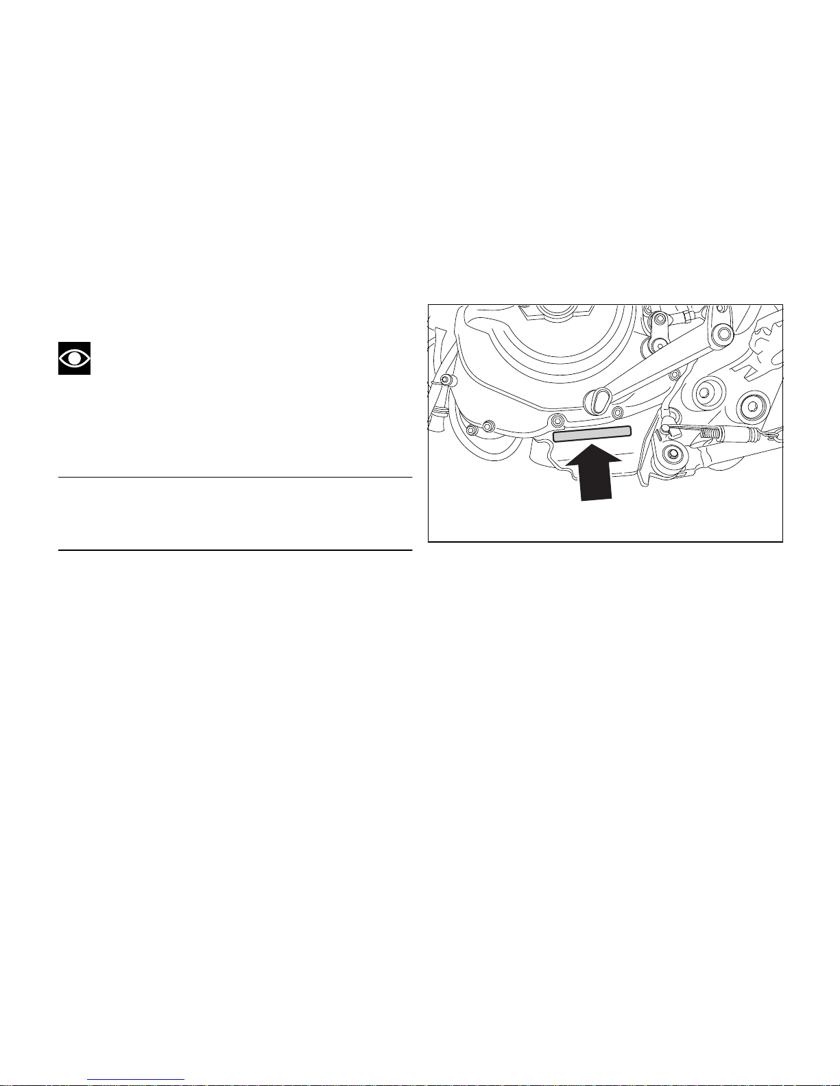
It is recommended to record the number of your
motorcycle's engine (Fig. 2) in the space below.
Engine number
Fig. 2
19
Page 21

Instrument panel (Dashboard)
Display settings and functions
1) LCD Dot-Matrix.
2) REV COUNTER (rpm).
Shows the engine rotation speed/minute (rpm).
3) NEUTRAL LIGHT N (GREEN).
Comes on when in neutral position.
4) HIGH BEAM LIGHT
(BLUE).
It turns on to indicate that the high beam lights are
on.
5) ENGINE OIL PRESSURE LIGHT
(RED).
Comes on when engine oil pressure is too low. It
must turn on at Key-On, but must turn off a few
seconds after the engine has started. It may shortly
come on when the engine is hot, however, it should
go out as the engine revs up.
1
2
7
59 6 47 8 3 10
Fig. 3
Important
If the ENGINE OIL light stays ON, stop the
engine or it may suffer severe damage.
20
Page 22

6) LOW FUEL LIGHT (AMBER YELLOW).
Comes on when fuel is low and there are about 4
litres of fuel left in the tank.
7) TURN INDICATOR LIGHTS (GREEN).
Illuminates and flashes when the turn indicator is in
operation. They both come on and flash when the
Hazard function is in operation.
8) “ENGINE/VEHICLE DIAGNOSIS - EOBD” LIGHT
(AMBER YELLOW).
It turns on in the case of “engine” and/or “vehicle”
errors and in some cases will lock the engine.
9) LIMITER LIGHT “OVER REV”/ TRACTION
CONTROL LIGHT “DTC” (RED).
Over rev light
No limiter Off
1st threshold - no.
RPM before the limiter threshold (*)
On - STEADY
Rev limiter (limiter engaged due to overrevving) (*)
On - Flashing
(*) depending on the model, each calibration of the
Engine Control Unit may have a different "setting" for
the thresholds that precede the rev limiter and
regarding the rev limiter itself.
DTC intervention light
No intervention Off
Advance cutting On - Steady
Injection cutting On - Steady
Note
Should both lights for Over rev Function
activation and DTC intervention come on, instrument
panel will give priority to Over rev Function.
21
Page 23

10) ABS LIGHT (AMBER YELLOW) (Fig. 3).
Engine off / speed below 5 Km/h
Light off Light flashing Light steady
- ABS disabled with the menu function (**)
ABS enabled but not functioning
yet
Engine on / speed below 5 Km/h
Light off Light flashing Light steady
- ABS disabled with the menu function
ABS enabled but not functioning
yet
Engine on / speed above 5 Km/h
Light off Light flashing Light steady
ABS enabled and functioning ABS disabled with the menu func-
tion
ABS disabled and not functioning
due to a problem
(**) The ABS should be considered actually disabled only if the light continues to flash after starting the
engine.
22
Page 24

Technological Dictionary
Acronyms and abbreviations used in the
Manual
ABS
Antilock Braking System
BBS
Black Box System
CAN
Controller Area Network
DDA
DUCATI Data Acquisition
DSB
Dashboard
DTC
DUCATI Traction Control
ECU
Engine Control Unit
Riding Mode
Rider can choose, among the three different pre-set
configurations (Riding Modes), the one that better
suits his/her riding style or path characteristics. Riding
Modes allow an immediate change of engine power
and output (ENGINE), braking control levels (ABS) and
traction control (DTC) intervention levels.
The available configurations are:
Sport, Touring and Urban (for Hypermotard and
Hyperstrada);
Race, Sport and Wet (for Hypermotard SP).
Within every Riding Mode, the rider can customise
any settings.
Ducati Traction Control (DTC)
The Ducati Traction Control system (DTC) supervises
the rear wheel slipping control and settings vary
through eight different levels that are programmed to
offer a different tolerance level to rear wheel slipping.
Each Riding Mode features a pre-set intervention
level. Level eight indicates system intervention
whenever a slight slipping is detected, while level one
is for very expert riders because it is less sensitive to
slipping and intervention is hence more rare.
Anti-lock Braking System (ABS)
Hypermotard ABS is an integral braking system with
rear wheel lift-up control, ensuring both a shorter
stopping distance and a higher braking stability. ABS
offers three different intervention levels, one for each
Riding Mode.
Ride by Wire (RbW)
23
Page 25

The Ride by Wire system is the electronic device that
controls throttle opening and closing. Throttle
twistrigp and throttle body are not mechanically
connected: this allows engine control unit adjusting
power output by simply changing throttle opening
angle.
The Ride by Wire system allows different engine
powers and outputs based on the selected Riding
Mode (Engine), but also serves as a control of rear
wheel slipping (DTC).
24
Page 26

Function push-buttons
1) CONTROL BUTTON
Button used to display and set instrument panel
parameters with the position " ".
2) CONTROL BUTTON
Button used to display and set instrument panel
parameters with the position " ".
3) HIGH-BEAM FLASH BUTTON FLASH
The high-beam flash button may also be used for LAP
functions.
4) TURN INDICATOR CANCEL BUTTON
The turn indicators on/off button may also be used for
navigating through the MENU and for activating the
"Riding Mode".
Press this button for 3 seconds to the left side to
activate the Hazard lights.
4
3
2
1
Fig. 4
25
Page 27

LCD - Main functions
Warning
Operate on instrument panel only when the
motorcycle is stopped. Do not operate on instrument
panel while you are riding the motorcycle under no
circumstances.
Data displayed on the main screen are as follows:
1) Engine RPM Indicator;
2) Vehicle Speed Indicator;
3) MENU 1 (Odometer, Trip 1, Trip 2, Trip Fuel,
Average Consumption, Instantaneous Consumption,
Average Speed and Trip Time) – UP-MAP Menu and
Riding Mode Set-up Menu;
4) MENU 2 (Engine Coolant Temperature, Ambient
Air Temperature and Clock);
5) Name of set Riding Mode;
6) Riding Mode DTC and ABS settings.
2
1
45
3
6
Fig. 5
Important
Do not ride the motorcycle if temperature
reaches the max. value as engine could suffer severe
damage.
26
Page 28

LCD - Parameter setting/display
Upon key-on, the instrument panel enables the rev
counter, which increases from 0 to 11,000 and
decreases going back to 0; the "DUCATI
HYPERSTRADA" lettering is enabled, in a scrolling
manner, on the Dot-Matrix area; warning lights come
on in sequence from the outside to the inside.
Once check is completed, the instrument panel
always displays Odometer (TOT), engine coolant
temperature and "Riding mode" functions as "main"
indicators.
1
2
Fig. 6
27
Page 29
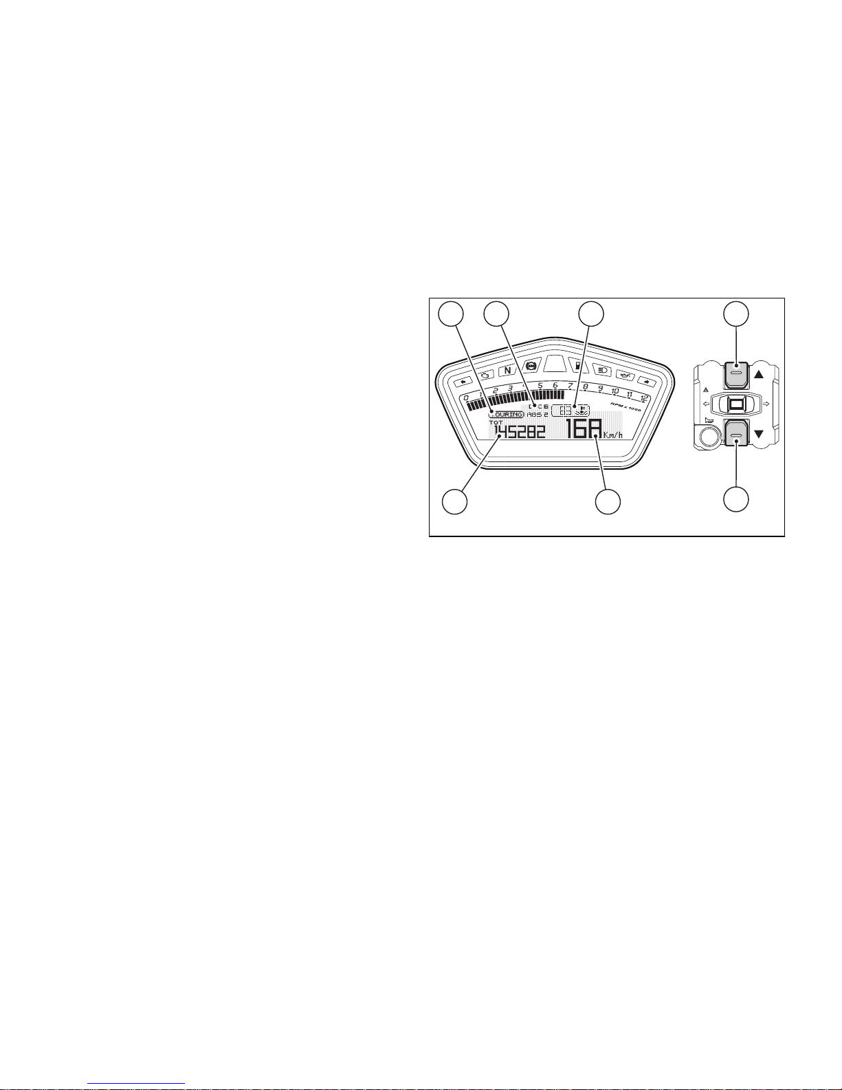
Once initial check is completed, the instrument panel
always goes to the "main" displaying page, with the
following information appearing on the display:
- MENU 1 (3): TOT - Odometer;
- MENU 2 (4): engine coolant temperature
indicator
- SET UP - Set "Riding Mode" indicator (5);
- Engine RPM indicator (RPM) (7);
- Vehicle speed indicator (8);
- "SERVICE" indicator (if active, only).
Press button (2) to scroll MENU 1 and shift to the
following functions:
- TRIP 1 - Trip meter 1;
- TRIP 2 - Trip meter 2;
- TRIP FUEL - Fuel reserve trip meter (if active,
only);
- CONS. AVG - Average Consumption;
- CONS. - Instantaneous Consumption;
- SPEED AVG - Average Speed;
- TRIP TIME - Trip Time.
14
83
5 6
2
Fig. 7
Press button (1) to scroll MENU 2 and shift to the
following Functions:
- AIR - Air Temperature;
- Clock.
28
Page 30
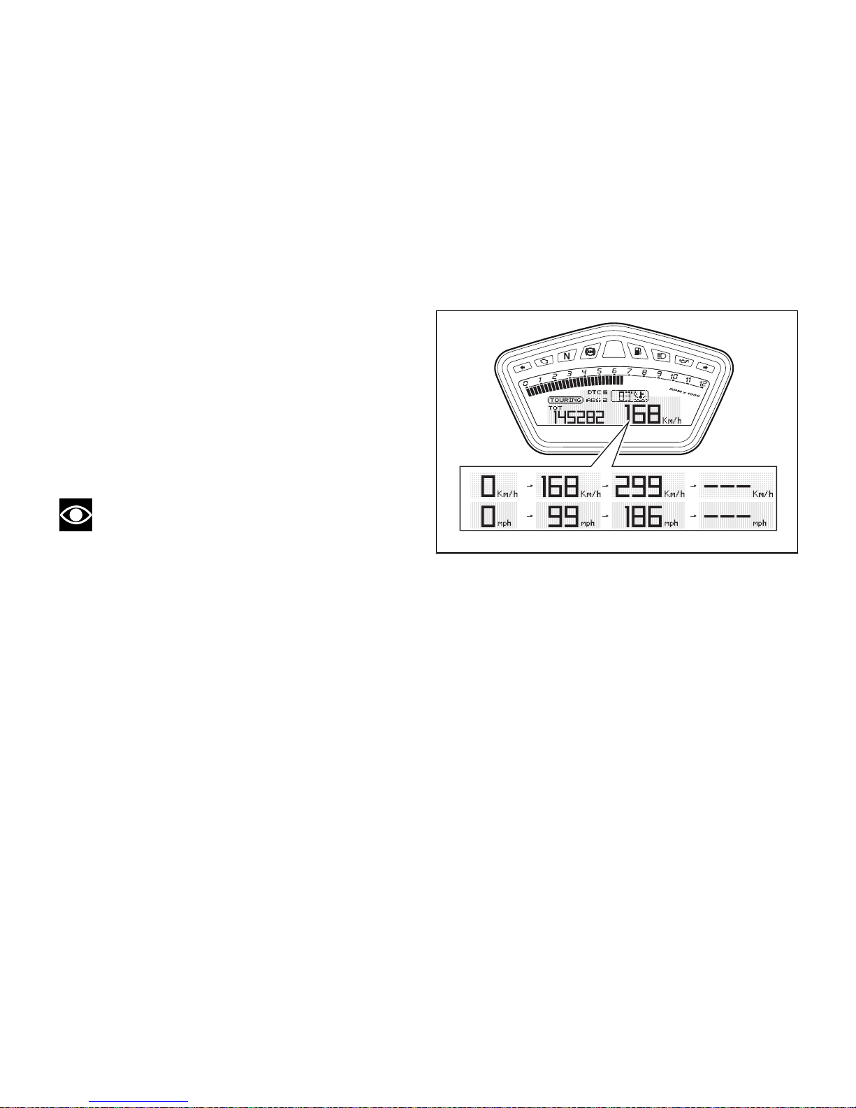
Vehicle speed indicator
This function shows vehicle speed (Km/h or mph,
based on the selected unit of measurement).
The instrument panel receives information about the
actual speed (calculated in km/h) and displays the
number increased by 5%.
Maximum speed displayed is 299 km/h (186 mph).
Over 299 km/h (186 mph) a series of dashes will be
displayed “- - -” (not flashing).
Note
If instrument panel does not receive any data, a
string of dashes "- - -" (not flashing) will be displayed.
Fig. 8
29
Page 31
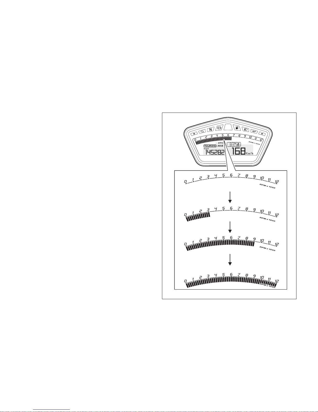
Engine rpm indicator (RPM)
This function shows engine rpm.
The instrument panel receives the engine rpm
information and displays it.
This information is displayed progressively from the
left to the right, identifying the rpms.
Fig. 9
30
Page 32
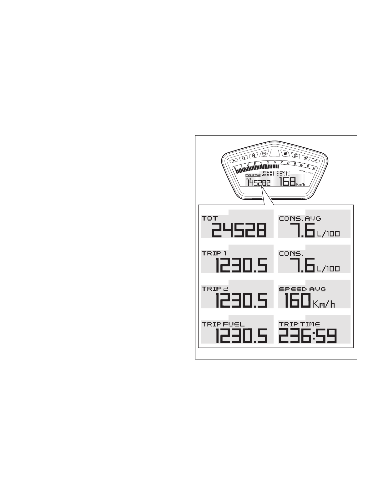
Menu 1 functions
MENU 1 functions are:
- Odometer (TOT);
- Trip meter 1 (TRIP1);
- Trip meter 2 (TRIP2);
- Fuel reserve trip meter (TRIP FUEL);
- Average Consumption (CONS. AVG);
- Instantaneous Consumption (CONS.);
- Average Speed (SPEED AVG);
- Trip Time (TRIP TIME).
Fig. 10
31
Page 33
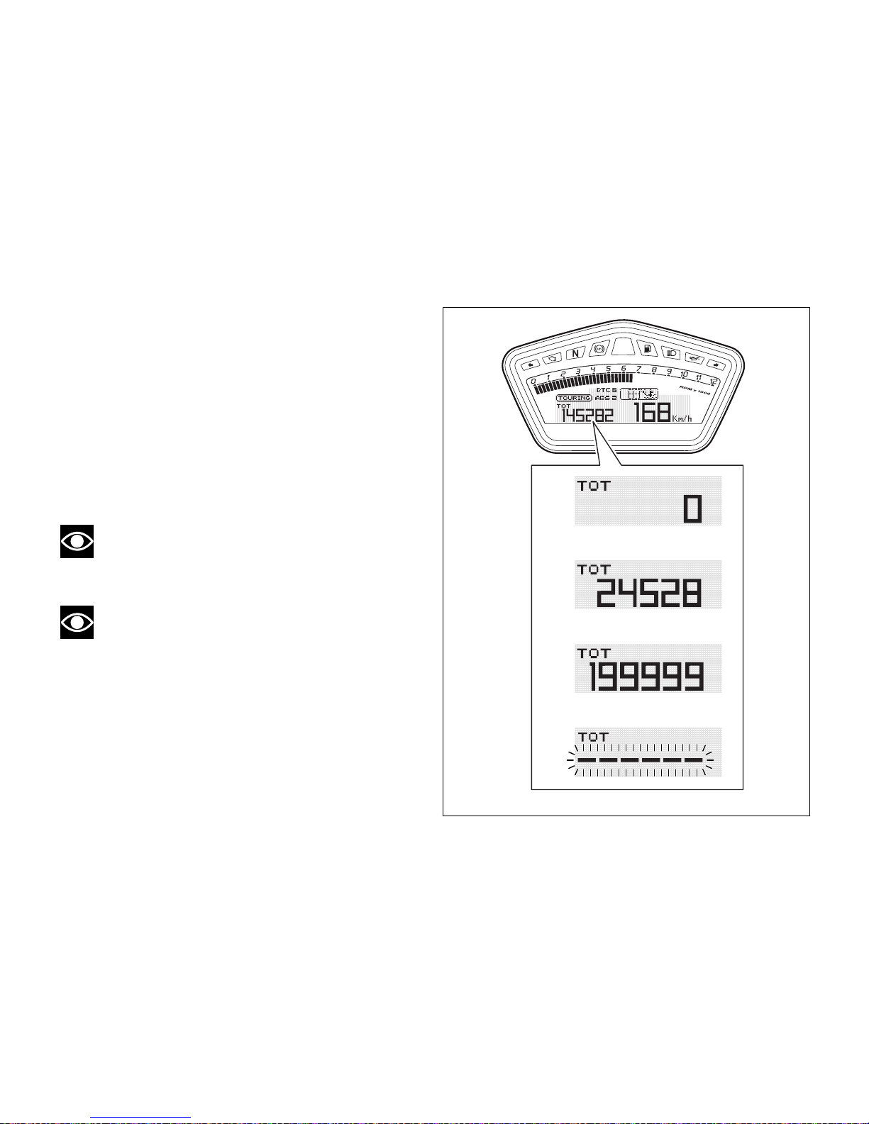
Menu 1 functions: Odometer (TOT)
This function shows the total distance travelled (km
or miles, based on the specific application).
Upon Key-On, the system automatically enters this
function.
The odometer reading is stored permanently and
cannot be reset.
If the distance travelled exceeds 199999 km (or
199999 miles), the value “199999” will be displayed
permanently.
Note
The reading is not lost in case of a power OFF
(Battery OFF).
Note
If a string of flashing dashes " ----- " is displayed
within odometer function, please contact a Ducati
Dealer or Authorised Service Centre.
Fig. 11
32
Page 34
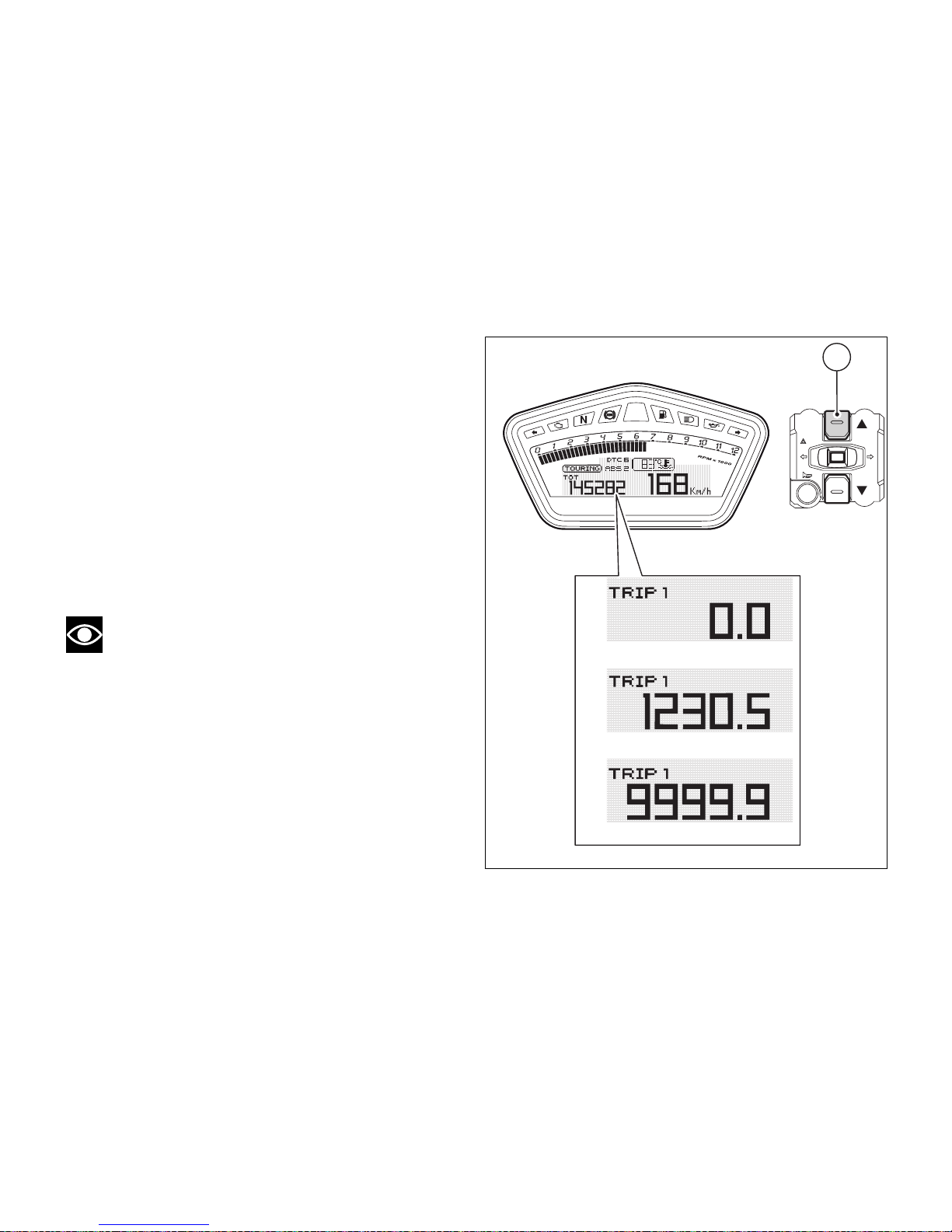
Menu 1 functions: Trip meter (TRIP 1)
This function shows the partial distance travelled (km
or miles, based on the specific application).
Holding button (1) pressed for 3 seconds when this
function is displayed resets the trip meter. When the
reading exceeds 9999.9, distance travelled is reset
and the meter automatically starts counting from 0
again. If the system measurement units are changed
at any moment, or if there is an interruption in the
power supply (Battery Off), the distance travelled is
reset and the count starts from zero (considering the
newly set unit of measurement).
Note
When this reading is reset, also "Average
Consumption", "Average Speed" and "Trip Time"
functions are reset.
1
Fig. 12
33
Page 35
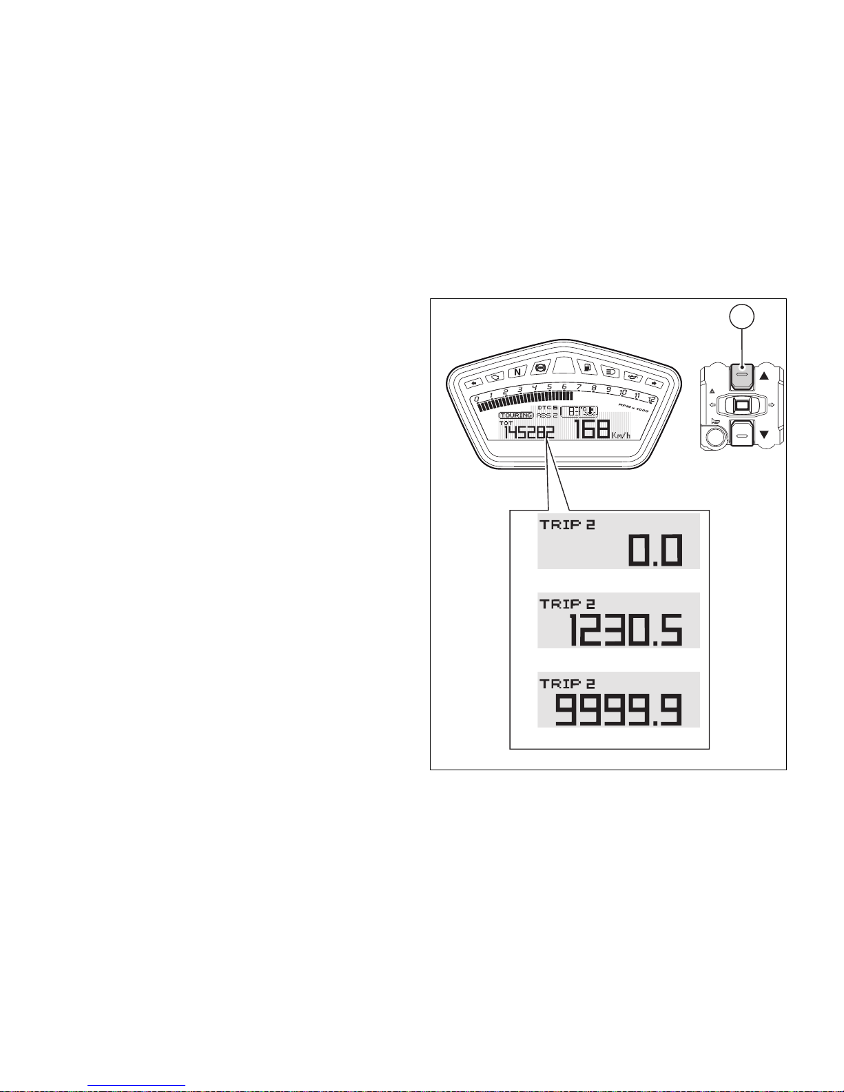
Menu 1 functions: Trip meter (TRIP 2)
This function shows the partial distance travelled (km
or miles, based on the specific application).
Holding button (1) pressed for 3 seconds when this
function is displayed resets the trip meter. When the
reading exceeds 9999.9, distance travelled is reset
and the meter automatically starts counting from 0
again. If the system measurement units are changed
at any moment, or if there is an interruption in the
power supply (Battery Off), the distance travelled is
reset and the count starts from zero (considering the
newly set unit of measurement).
1
Fig. 13
34
Page 36

Menu 1 functions: Partial fuel reserve
counter (TRIP FUEL)
This function shows the distance travelled (km or
miles, based on the specific application) on fuel
reserve. As soon as the fuel reserve warning light
comes on, whatever the displayed function, the TRIP
FUEL will be automatically enabled; afterwards the
other functions of Menu 1 can be scrolled by pressing
button (2).
Trip fuel reading remains stored even after Key-Off
until the vehicle is refuelled. Count is interrupted
automatically as soon as fuel is topped up to above
minimum level. When the reading exceeds 9999.9,
distance travelled is reset and the meter
automatically starts counting from 0 again.
When the TRIP FUEL function is disabled, the
corresponding page inside Menu 1 will not be
available.
2
Fig. 14
35
Page 37
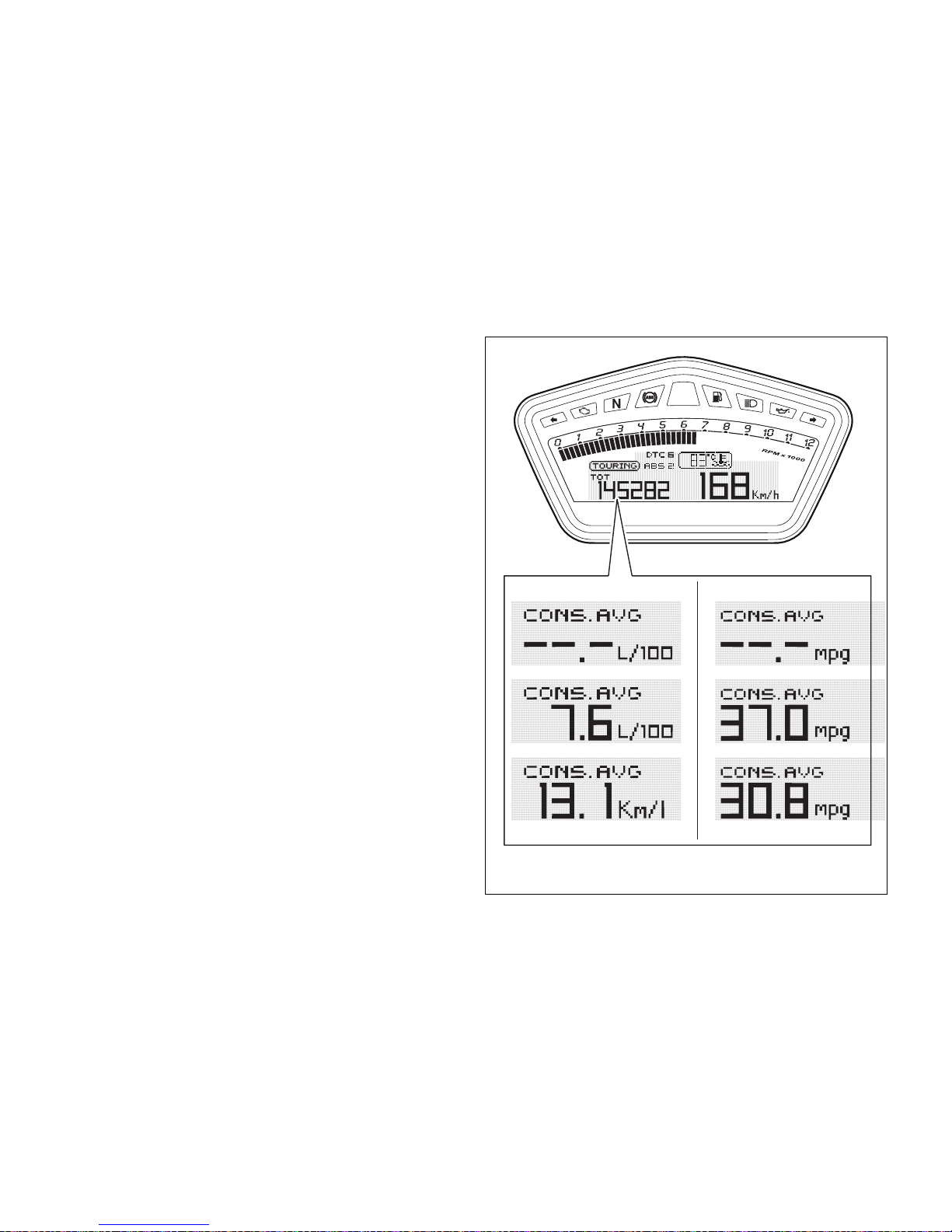
Menu 1 functions: Average fuel
consumption indicator (CONS. AVG)
This function indicates the “average” fuel
consumption. The calculation is made considering
the quantity of fuel used and the distance travelled
since Trip 1 was last reset. When Trip 1 is reset, the
value is reset and the first value available is displayed
10 seconds after the reset. Dashes “- -.-” are shown
on the display during the first 10 seconds when the
value is not yet available. For Europe and Japan
versions, the value is expressed in "L / 100" (litres /
100 Km); the "Km / L" (kilometres / litre) unit can
nevertheless be set through the "Special Setting"
function. For the UK version the reading is in “mpg
UK” (miles per UK gallon).
The active calculation phase occurs when the engine
is running and the vehicle is stopped (moments when
the vehicle is not moving and the engine is off are not
considered).
Fig. 15
36
Page 38
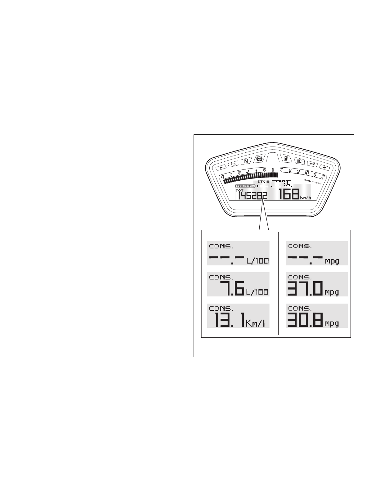
Menu 1 functions: Instantaneous fuel
consumption indicator (CONS.)
This function indicates the “instantaneous” fuel
consumption. The calculation is made considering
the quantity of fuel used and the distance travelled
during the last second. For Europe and Japan
versions, the value is expressed in "L / 100" (litres /
100 Km); the "Km / L" (kilometres / litre) unit can
nevertheless be set through the "Special Setting"
function. For the UK version the reading is in “mpg
UK” (miles per UK gallon).
The active calculation phase only occurs when the
engine is running and the vehicle is moving
(moments when the vehicle is not moving when
speed is equal to 0 and/or when the engine is off are
not considered). Dashes “- -.-”. are shown on the
display when the calculation is not made.
Fig. 16
37
Page 39
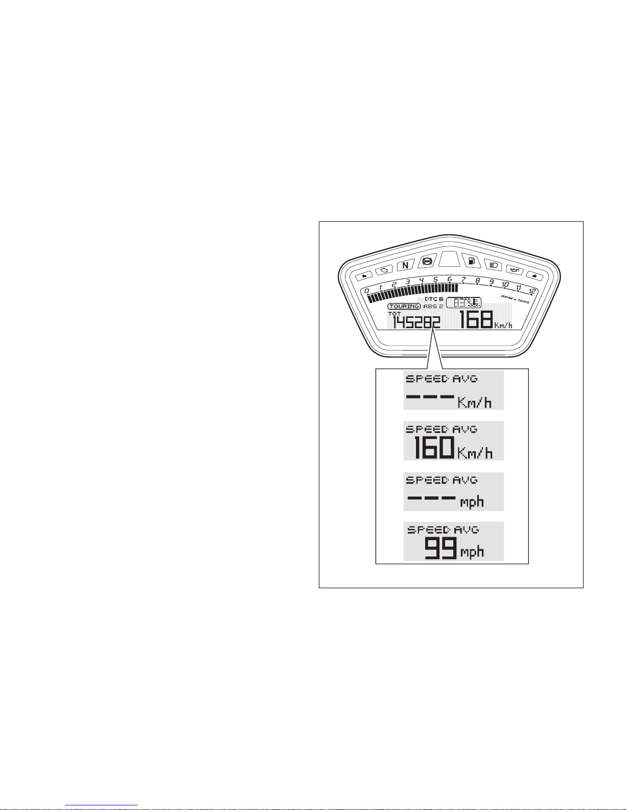
Menu 1 functions: Average speed indicator
(SPEED AVG)
This function shows the average speed of the
motorcycle.
The calculation considers the distance and time since
Trip 1 was last reset. When Trip 1 is reset, the value
is reset and the first value available is displayed 10
seconds after the reset.
Dashes “- -.-” are shown on the display during the
first 10 seconds when the value is not yet available.
The active calculation phase occurs when the engine
is running and the vehicle is stopped (moments when
the vehicle is not moving and the engine is off are not
considered).
The calculated value is displayed increased by 5% to
align it with the vehicle indicated speed.
Fig. 17
38
Page 40
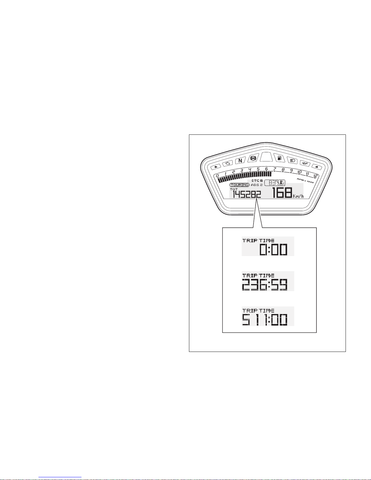
Menu 1 functions: Trip time indicator
(TIME TRIP)
This function shows the vehicle trip time.
The calculation considers the time since Trip 1 was
last reset. When Trip 1 is reset, this value is reset as
well.
The active phase calculation occurs when the engine
is running and the vehicle is stopped (when the
vehicle is not moving and the engine is off the time
is automatically stopped and restarts when the
counting active phase starts again).
Fig. 18
39
Page 41
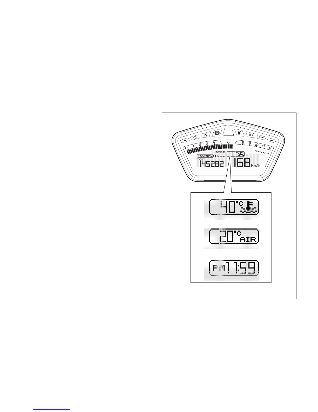
Menu 2 functions
MENU 2 functions are:
- Engine coolant temperature;
- Ambient air temperature(AIR);
- Clock.
Fig. 19
40
Page 42
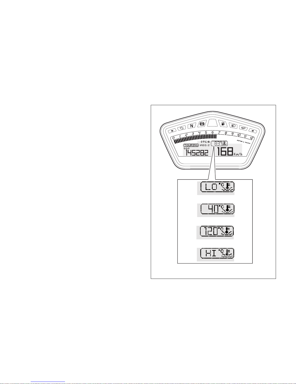
Menu 2 functions: Coolant temperature
This Function is used to display coolant temperature
(°C or °F, based on the specific application).
The instrument panel receives the temperature
reading value and displays it.
The reading is indicated as follows:
- if the reading is between - 39°C and +39°C “LO”
is shown flashing on the instrument panel
(steady);
- if the reading is between +40°C and +120°C it
appears on the instrument panel (steady);
- if reading is +121 °C or higher, "HI" is shown
flashing on the information panel;
Fig. 20
41
Page 43
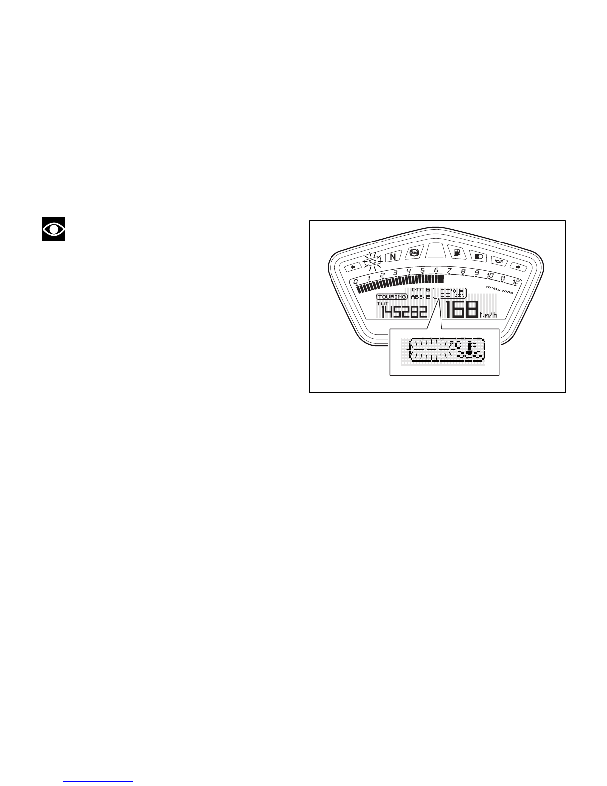
Note
If the sensor is in fault, the three flashing dashes
("- - -") will be displayed and, at the same time, the
"Engine/Vehicle Diagnosis - EOBD" light will come on.
Fig. 21
42
Page 44
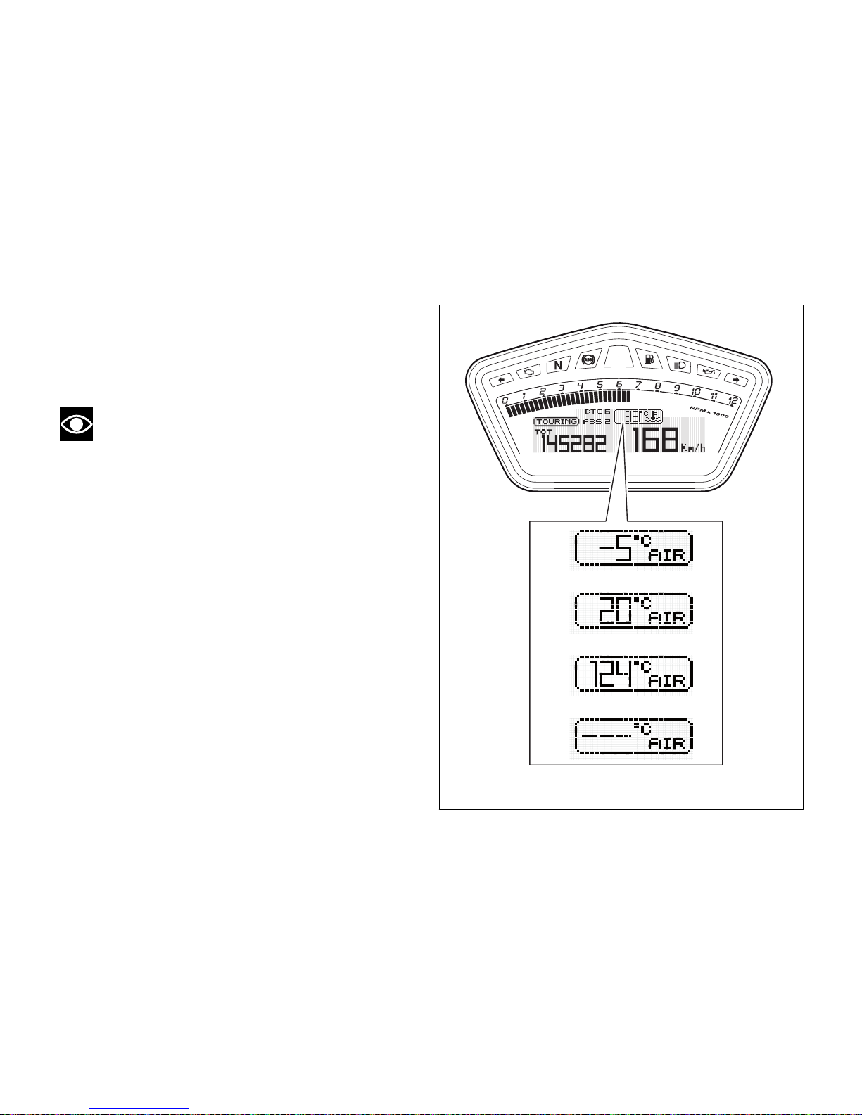
Menu 2 functions: Air temperature (AIR)
This function indicates ambient temperature.
Instrument panel takes temperature value directly
from sensor and displays it.
Note
When the motorcycle is stopped, the engine
heat could influence the displayed temperature.
Fig. 22
43
Page 45
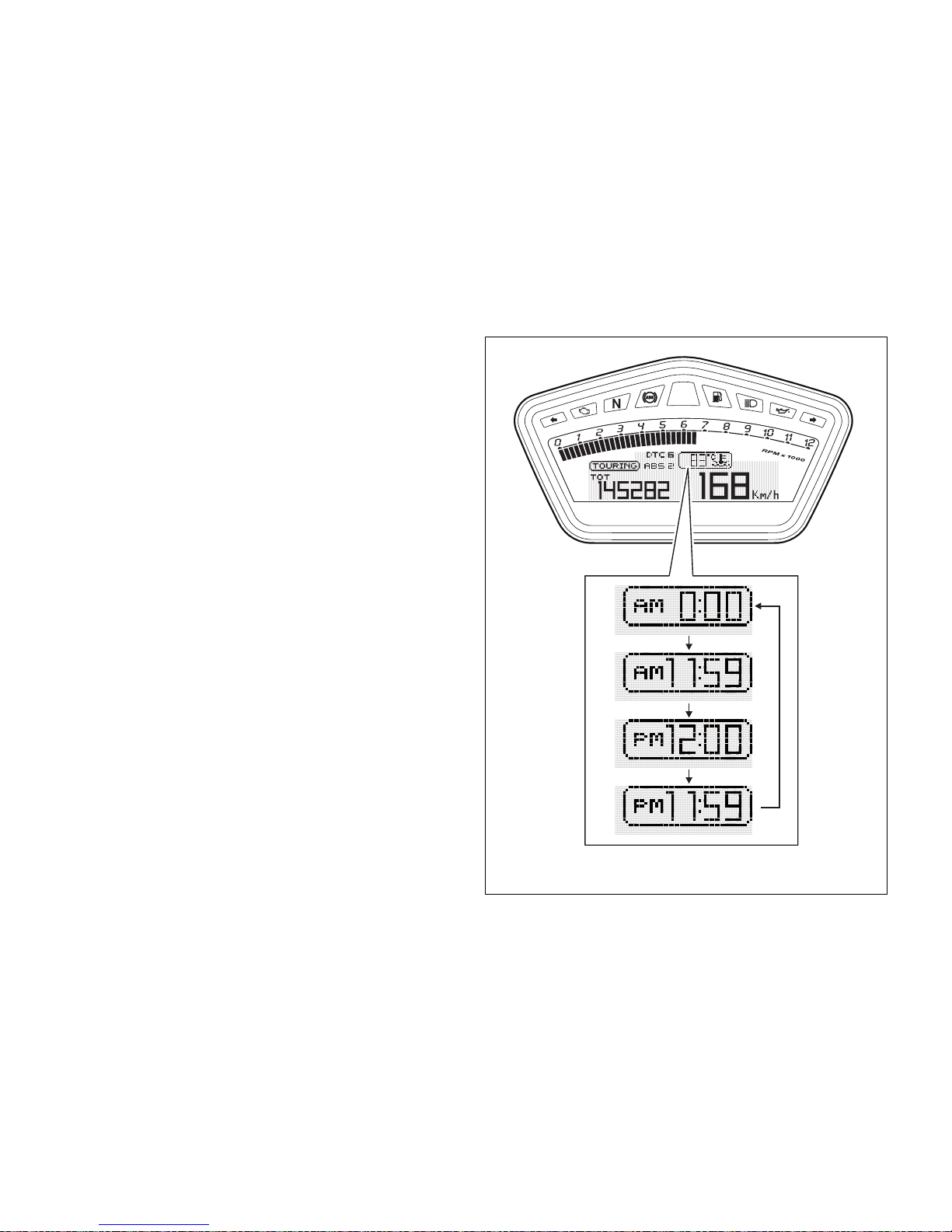
Menu 2 functions: Clock
This function shows the time.
Time is always displayed as follows:
- AM from 0:00 to 11:59;
- PM from 12:00 to 11:59.
If battery power is suddenly cut off (Batt-OFF), when
battery power is restored and upon next Key-On, the
clock is reset and restarts operating from "0:00".
Fig. 23
44
Page 46
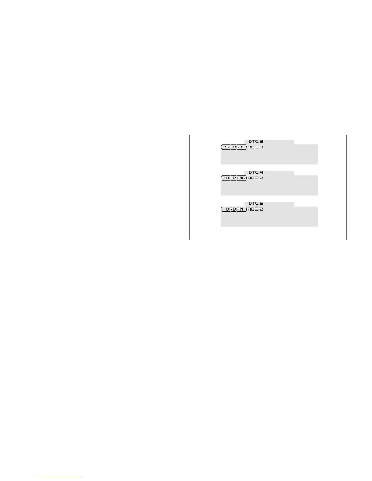
SET UP - Riding Style set indication
This function indicates the Riding Mode set for the
vehicle.
Each riding mode can be changed using the Riding
Mode function.
The set riding mode, the Traction Control level (DTC)
and corresponding ABS level are indicated.
Three different riding modes can be set: SPORT,
TOURING, URBAN.
Fig. 24
45
Page 47
SERVICE function - Maintenance
interventions
This indicator is used to inform the user to contact an
authorised Ducati Service Centre to carry out the
scheduled maintenance operations (service) on the
vehicle.
All maintenance indicators can be "Reset" only by the
authorised Ducati Service Centre that will service the
vehicle.
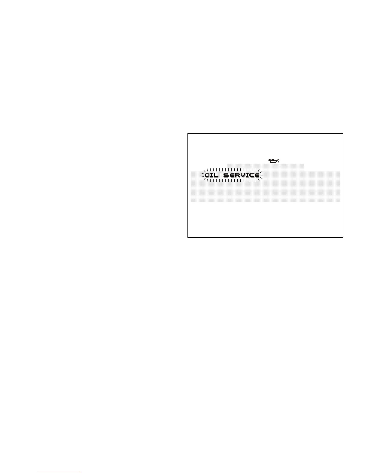
First indicator: OIL SERVICE (1000 Km)
The first maintenance indicator is the "OIL SERVICE"
signal, coming on when the first 1,000 km (600 miles)
are reached on the odometer. The "OIL SERVICE"
indicator will come on flashing for 5 seconds upon
every Key-ON; while the OIL SERVICE symbol will
remain steady on. Both signals will be active until
"Reset" by the authorised Ducati Service Centre.
Fig. 25
46
Page 48
Mileage countdown indicator - OIL SERVICE or
DESMO SERVICE (countdown)
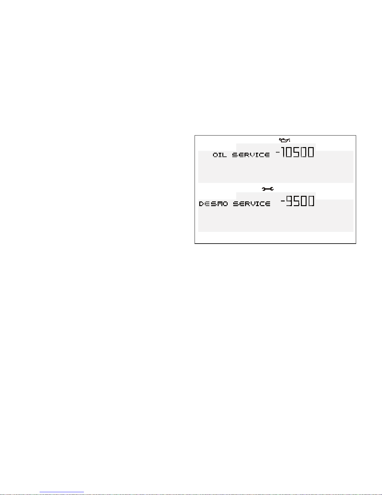
After the "OIL SERVICE" indicator has been "reset" for
the first time (after 1,000 km), upon every Key-On the
instrument panel will show the following service
indicator ("OIL SERVICE" or "DESMO SERVICE") as
well as the mileage countdown indicator.
"OIL SERVICE" or "DESMO SERVICE" indicators, as
well as the relevant symbols and mileage countdown,
will come steady on for 2 seconds upon every KeyOn.
When just 1,000 km are left before service threshold
is reached, the indicator will be enabled (steady on)
upon Key-On for 5 seconds (instead of 2 seconds).
Both signals will be active until "Reset" by the
authorised Ducati Service Centre.
Fig. 26
47
Page 49
OIL SERVICE or DESMO SERVICE indicator
(mileage reached)
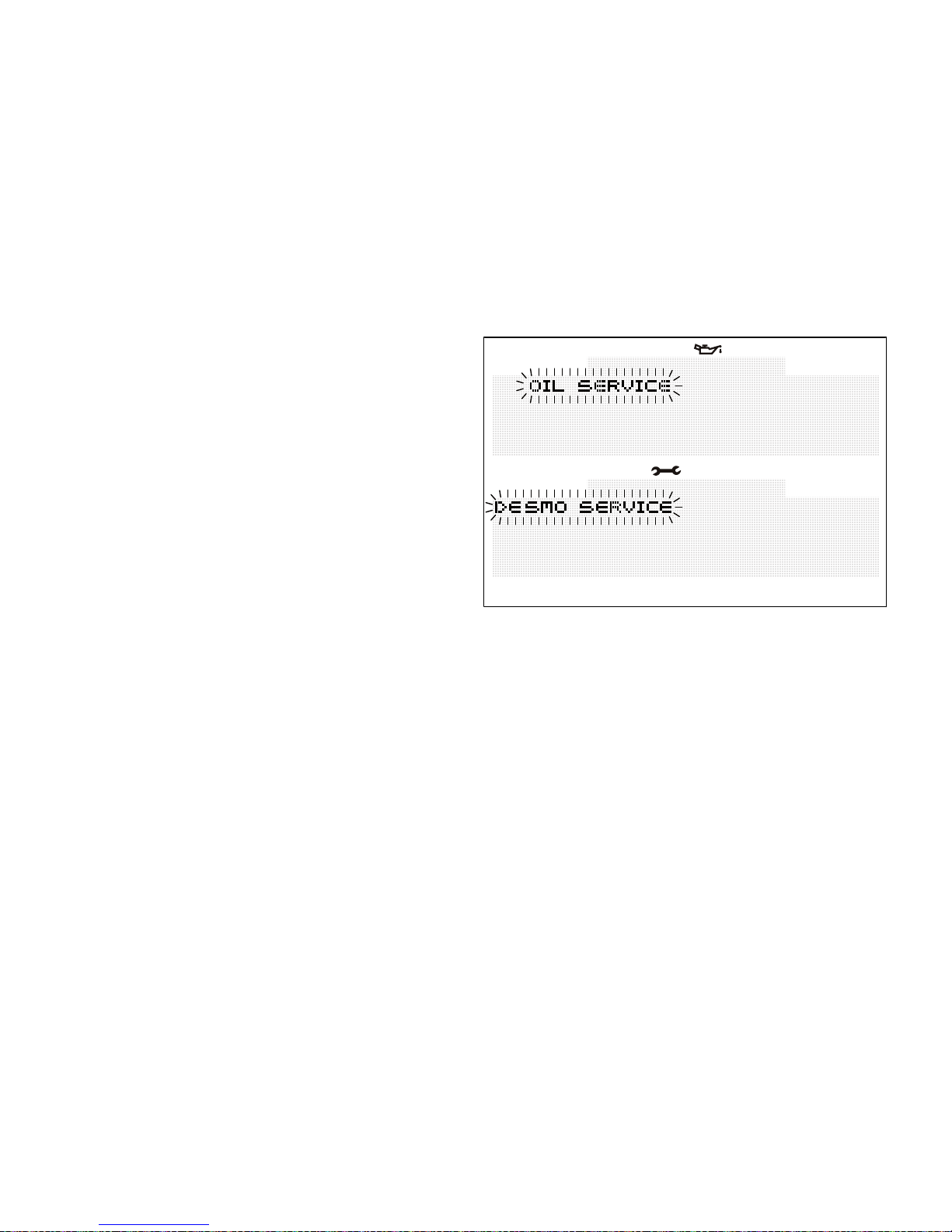
Whenever the threshold required to carry out a
maintenance operation is reached, the type of
operation to be carried out ("OIL SERVICE" or
"DESMO SERVICE") will come on upon each Key-On.
The "OIL SERVICE" or "DESMO SERVICE" indicators
will come on (flashing) upon each Key-On for 5
seconds; while the OIL SERVICE or DESMO
SERVICE symbols will be displayed steady on.
Both signals will be active until "Reset" by the
authorised Ducati Service Centre.
Fig. 27
48
Page 50
Active / not active ERRORS indication
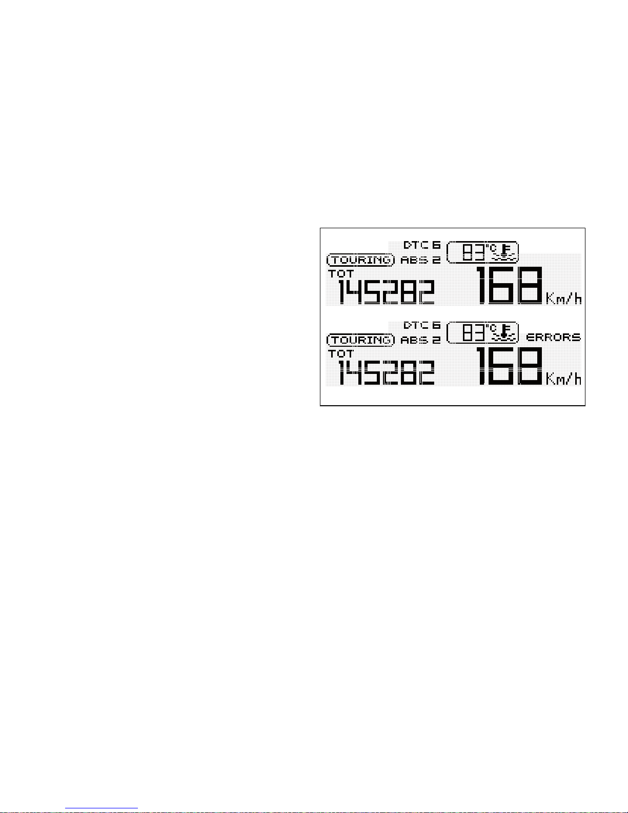
This function indicates that one or more errors are
present.
The type and number of errors can be displayed using
the Setting Menu through the ERRORS function;
when "ERRORS" is off, no errors are present.
Fig. 28
49
Page 51
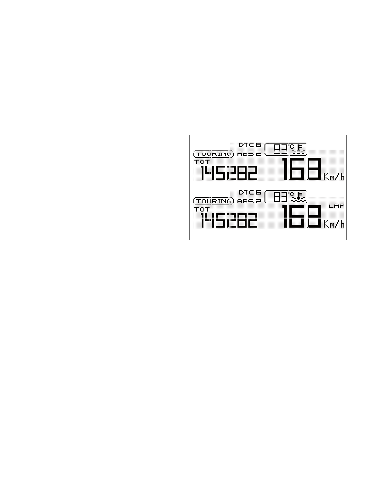
Indication if the "LAP" function is active/not
active
This function indicates if the LAP function (Lap time)
is active.
When "LAP" is off, function is disabled.
Fig. 29
50
Page 52
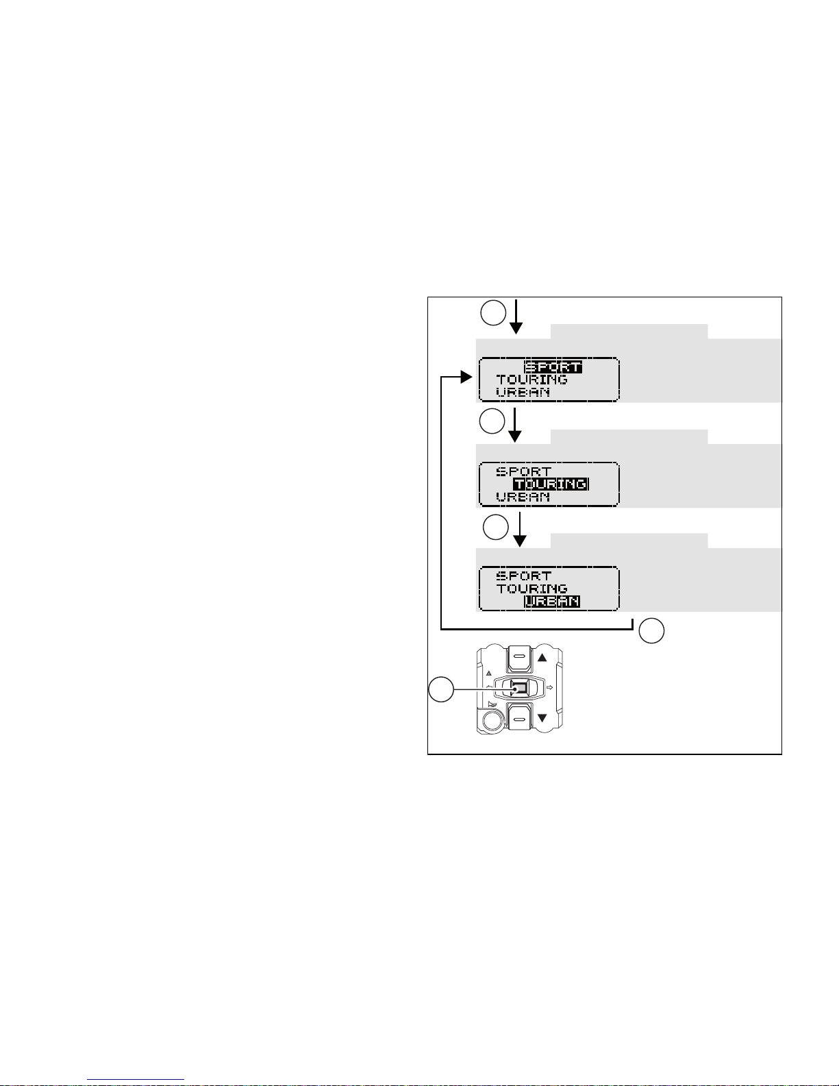
Riding Mode SET UP function (riding style
change)
This function allows changing vehicle riding mode.
Each riding mode is associated to a different
intervention level of the traction control system (DTC
- Ducati Traction Control), a different braking control
(ABS - Anti-lock Braking System) and a different
engine output and power (Engine). To change bike
riding mode, simply press button (4) once, and the
corresponding menu will be displayed. Whenever
vehicle riding mode is changed, the following
features will also be changed:
- traction control system “DTC” intervention level
(1, 2, 3, 4, 5, 6, 7, 8 and OFF);
- "Engine" power that will consequently change
also throttle behaviour (HIGH, MEDIUM and
LOW);
- "ABS" system calibration (1, 2 and OFF).
Whenever button (4) is pressed, instrument panel will
display all riding modes one after the other in a scroll
up-and-down view.
4
4
4
4
4
Fig. 30
51
Page 53
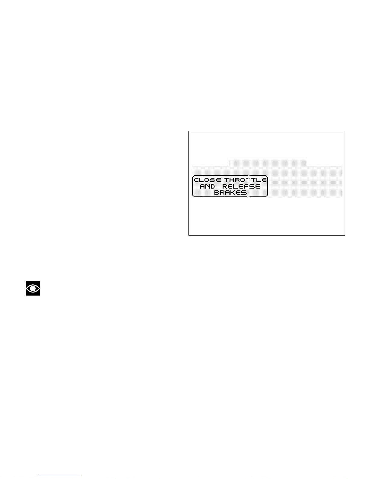
Once the desired riding mode is highlighted, keep
button (4) pressed for 3 seconds and instrument
panel will check throttle control position and front and
rear brake pressure:
- if throttle control is "closed" and brakes are
released or vehicle is stopped, the instrument
panel will confirm the selected riding mode (*)
and go back to the standard screen view ;
- if throttle control is "open" or brakes are pressed
and vehicle is moving, instrument panel will
enable the "CLOSE THROTTLE AND RELEASE
BRAKES" indicator on the display and, only when
all the required conditions are fulfilled (closed
throttle and released brakes or vehicle stopped)
the instrument panel will confirm the selected
riding mode (*) and go back to the standard
screen view.
Note
(*) If the change of Riding mode is associated
with the ABS change of state from ON to OFF or viceversa, the instrument panel also starts the "procedure
for disabling or activating the ABS", respectively,
upon confirmation of the selected riding mode.
Fig. 31
If throttle control is not closed and brakes are not
released or vehicle is not stopped within 5 seconds
after the "CLOSE THROTTLE AND RELEASE
BRAKES" warning is displayed, the Riding Mode
change selection procedure will not be executed and
the instrument panel will go back to the standard
screen view without any setup change.
52
Page 54
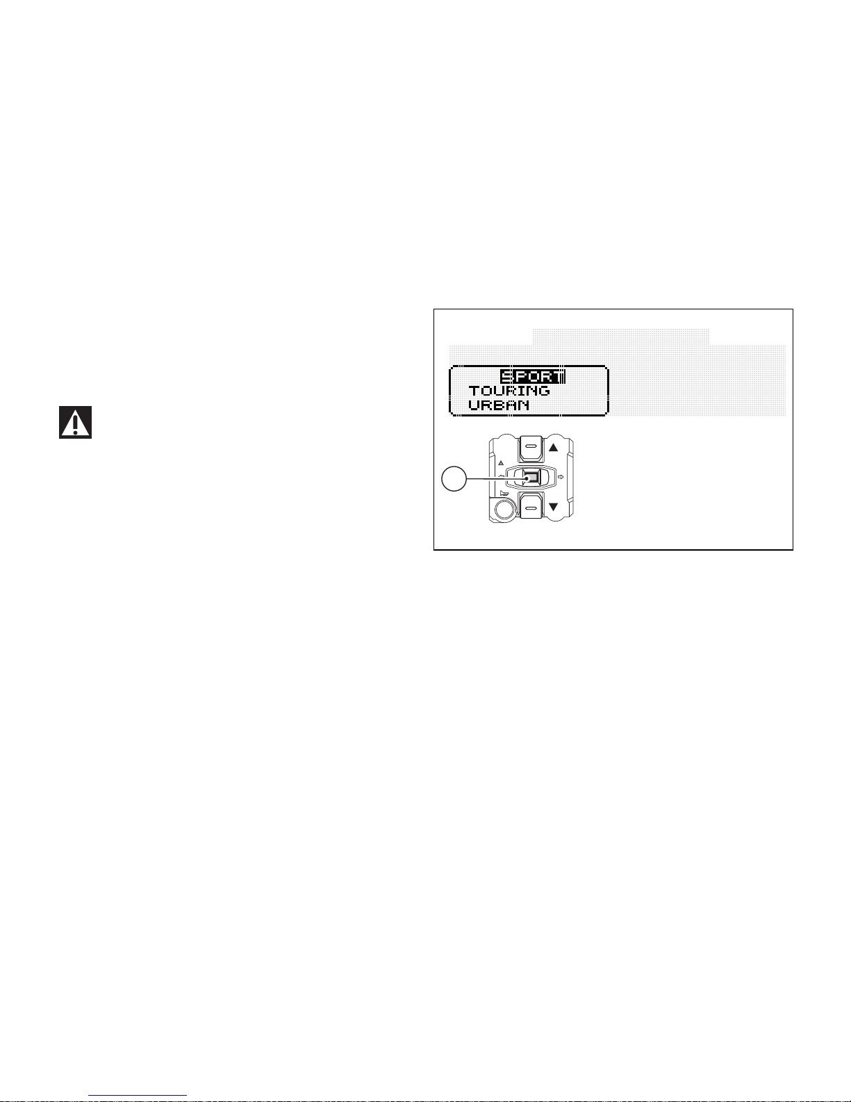
If the "SET UP" menu is enabled and button (4) is not
pressed for 10 consecutive seconds, the instrument
panel will automatically quit the displayed page
without any setup change.
Warning
Ducati recommends changing the Riding mode
when the motorcycle is stopped. If the riding mode
is changed while riding, be very careful (it is
recommended to change the Riding mode at a low
speed).
4
Fig. 32
53
Page 55
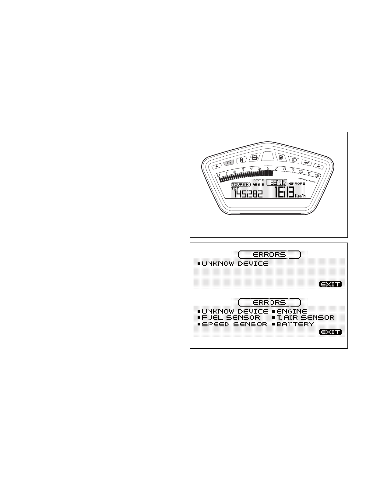
Error display function (ERRORS)
This function identifies any abnormal vehicle
behaviours.
The instrument panel activates any abnormal vehicle
behaviours in real time (ERRORS).
If one or more "errors" occur during bike operation,
the "ERROR" indicator will appear on display RH side.
Under these circumstances (one ore more errors
present) the "EOBD" warning light will always come
on.
To display error list, access the Setting Menu and
select the "ERRORS" page; this page will be active
only if at least one error is present.
Fig. 33
Fig. 34
54
Page 56

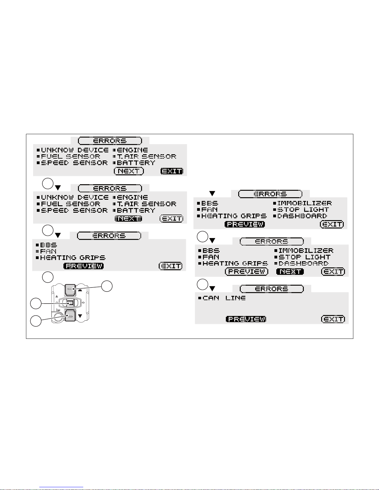
If one ore more errors are present, also "NEXT" and
"PREVIEW" will be automatically activated in order to
go from one page to another.
To go from one page to another, select "NEXT" and
"PREVIEW" with buttons (1) and (2), then press button
(4).
The Setting Menu can be quit and accessed at any
time by simply pressing button (4), with the
highlighted "EXIT" indicator.
Warning
When one or more errors are displayed, always
contact a Ducati Dealer or authorised Service Centre.
55
Page 57
1
2
4
1
2
2
1
2
Fig. 35
56
Page 58
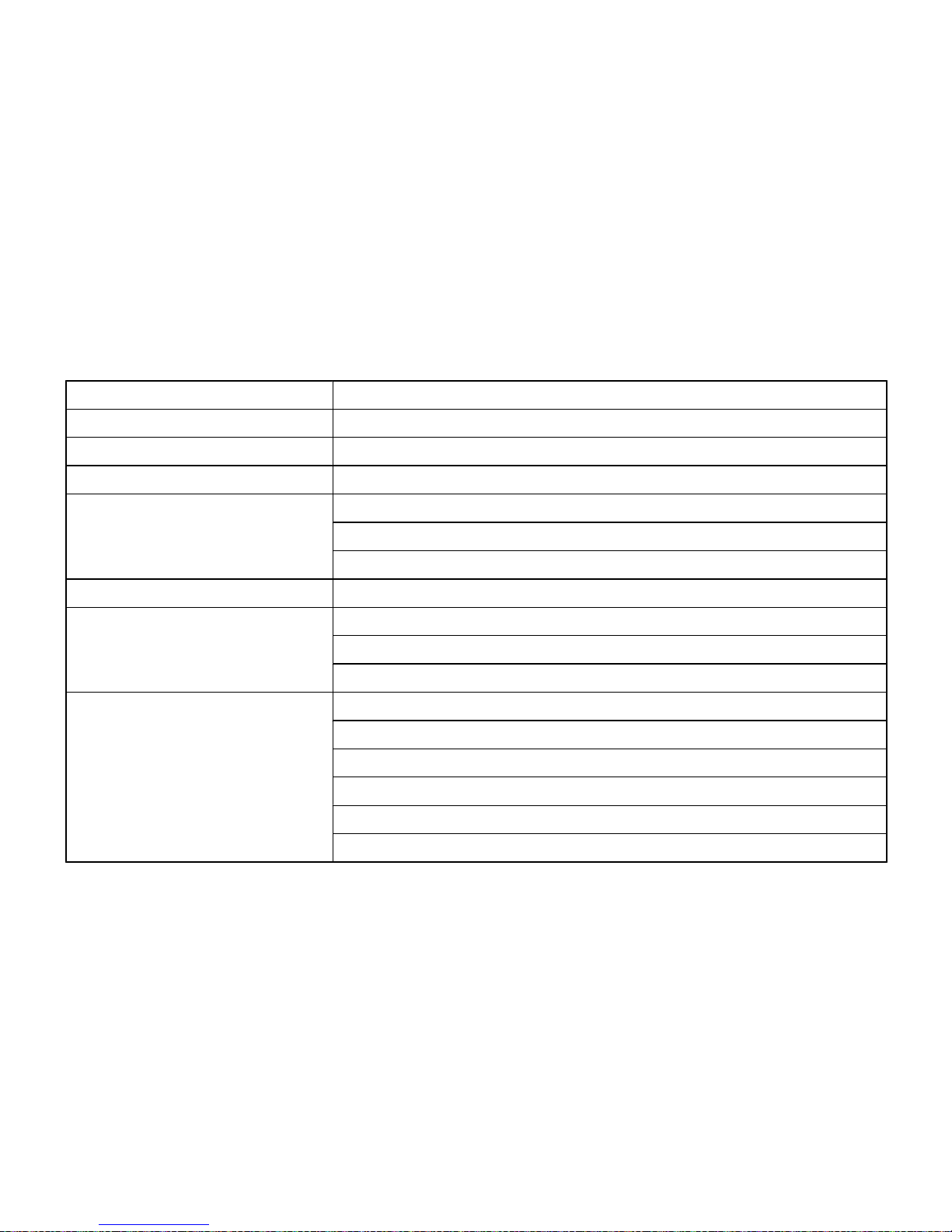
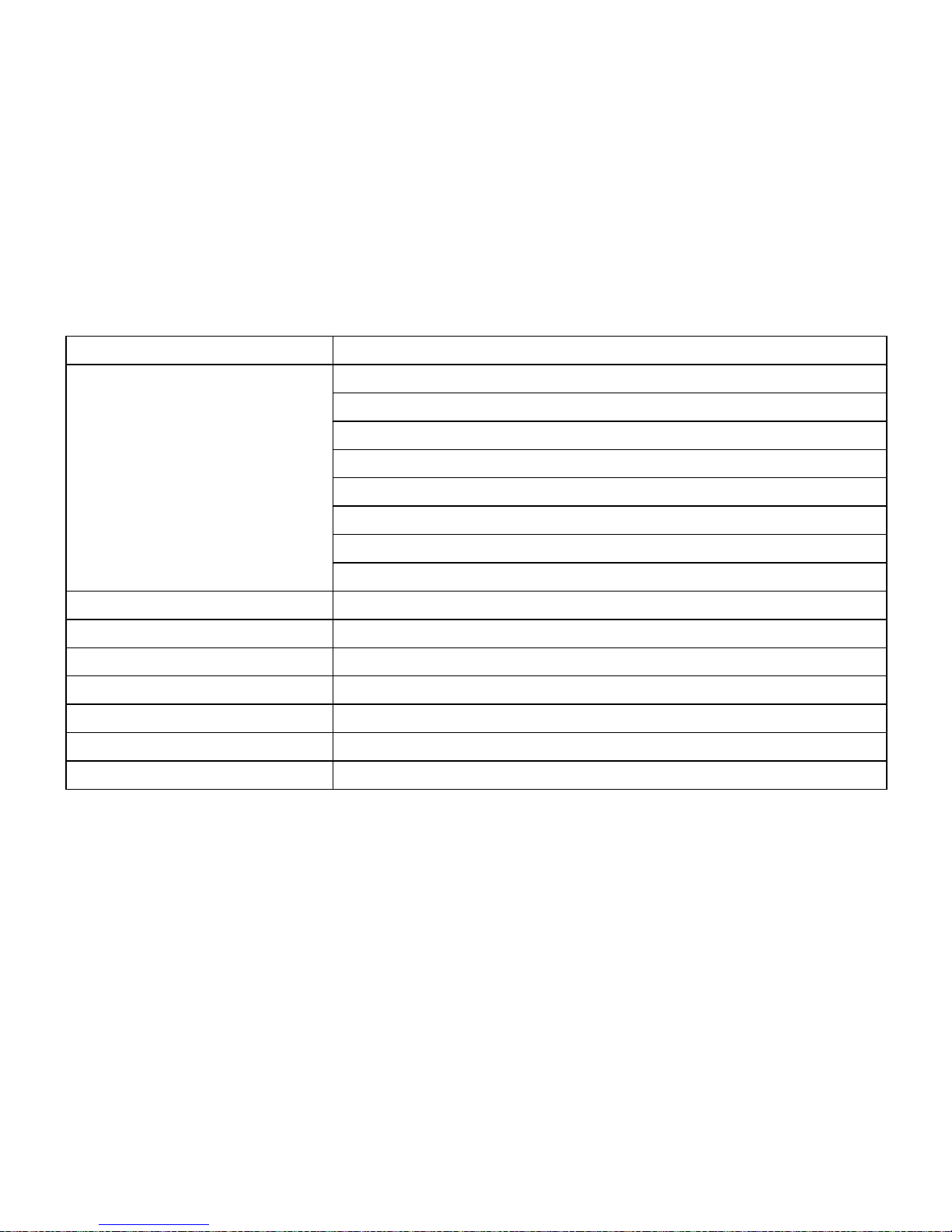
Hereinafter is a table listing the possible errors:
Displayed error Description
CAN LINE CAN line "BUS Off" (communication line of the several control units)
UNKNOWN DEVICE Control unit not acknowledged by the system - wrong SW
ABS (Antilock Braking System) ABS control unit faulty communication / operation
BBS (Black Box System) BBS control unit faulty communication / operation
BBS control unit general malfunction
Exhaust valve motor malfunction EXVL
DASHBOARD DSB control unit faulty communication / operation
IMMOBILIZER No key
Key not acknowledged
Faulty antenna
ENGINE ECU control unit faulty communication / operation
General malfunction of the ECU control unit
Throttle position sensor malfunction
Throttle motor and/or relay malfunction
Pressure sensor malfunction
Engine coolant temperature sensor malfunction
57
Page 59
Displayed error Description
Intake duct air temperature sensor malfunction
Injection relay malfunction
Ignition coil malfunction
Injector malfunction
Engine rpm sensor malfunction
Lambda sensor or Lambda sensor heater malfunction
Vehicle starting relay malfunction
Secondary air sensor malfunction
FUEL SENSOR Reserve NTC sensor malfunction
SPEED SENSOR Front and/or rear speed sensor malfunction
BATTERY Battery voltage too high or too low
STOP LIGHT Stop light not working
FAN Electric cooling fan malfunction
T_AIR SENSOR Ambient air temperature sensor malfunction
H.GRIPS Malfunction of one or both heated grips
58
Page 60

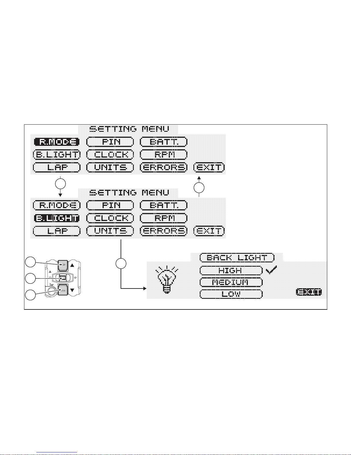
SETTING MENU
This menu is used to set/enable some motorcycle
functions.
To access the Setting Menu, keep button (2) pressed
for two seconds; once this menu is accessed it will
no longer be possible to scroll functions on the
Display.
Important
For safety reasons, the setting menu can be
accessed only when vehicle speed is below or equal
to 20 Km/h; if this menu is accessed and vehicle
speed is above 20 Km/h, instrument panel will
automatically quit it and shift back to "main" screen.
Setting menu includes:
- riding mode customisation (R.MODE);
- backlighting adjustment (B.LIGHT);
- lap time activation and displaying (LAP);
- PIN CODE activation and editing (PIN);
- clock setup (CLOCK);
- measurement unit setup (UNITS);
- battery voltage indicator (BATT.)
- Engine RPM indicator (RPM);
- error indicator, only if one or more errors are
present (ERRORS);
- EXIT.
To quit the setting menu, use buttons (1) and (2) to
highlight the "EXIT" wording, then press button (4).
59
Page 61
1
2
4
1
2
4
Fig. 36
60
Page 62

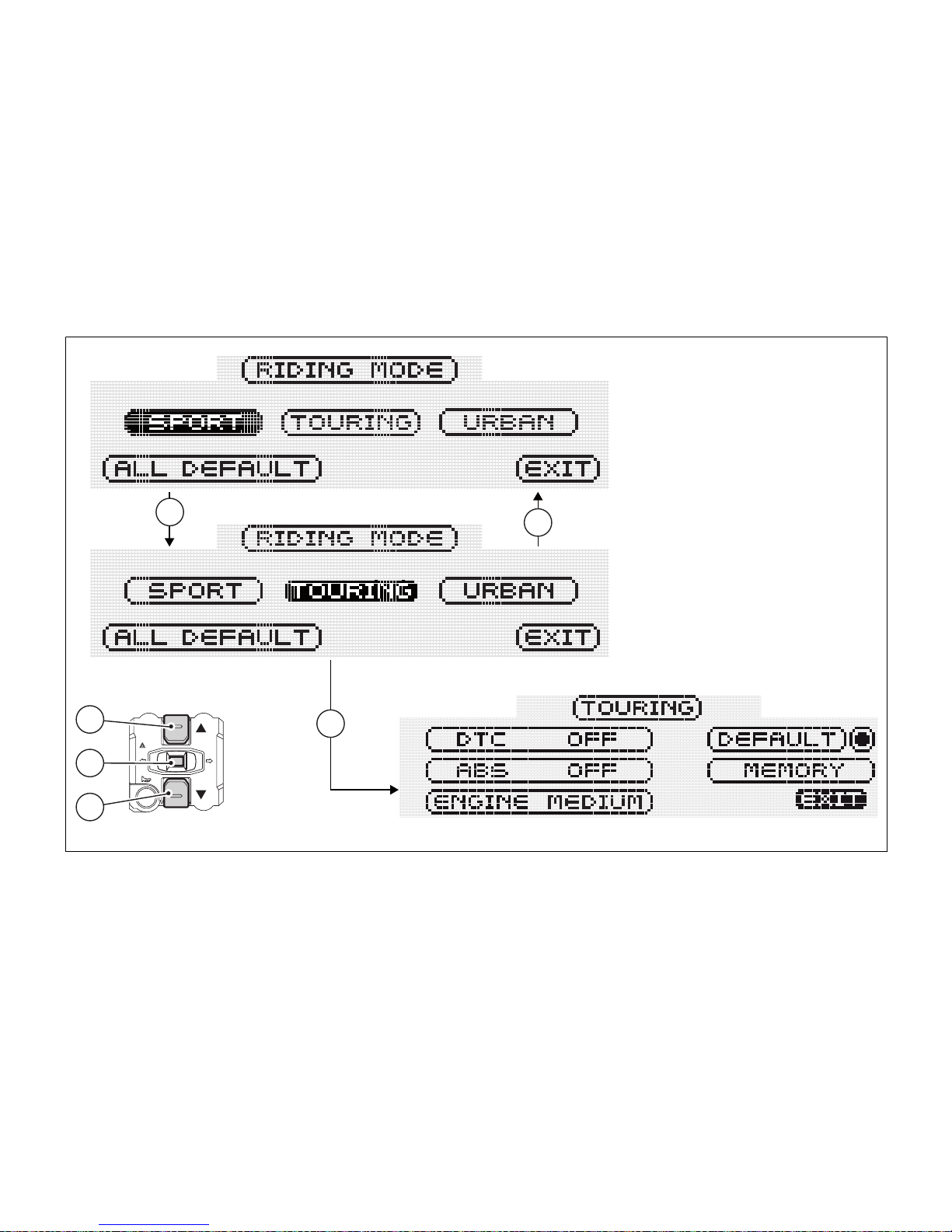
Customising Riding Modes (R.MODE)
This function customises each riding style.
To display this function, access the Setting Menu and
select the R.MODE page.
When accessing this function, the three riding modes
- SPORT, TOURING and URBAN - will be displayed.
The ALL DEFAULT function will also be displayed;
this function is used to reset Ducati default setup
parameters for all riding modes.
Buttons (1) and (2) can also be used to select the
riding mode you wish to edit or the ALL DEFAULT
function.
Note
If on ALL DEFAULT lettering right side a symbol
is displayed, this means that the default setup is
active, namely that the parameters shown are those
set up by Ducati.
61
Page 63
1
2
4
1
2
4
Fig. 37
62
Page 64
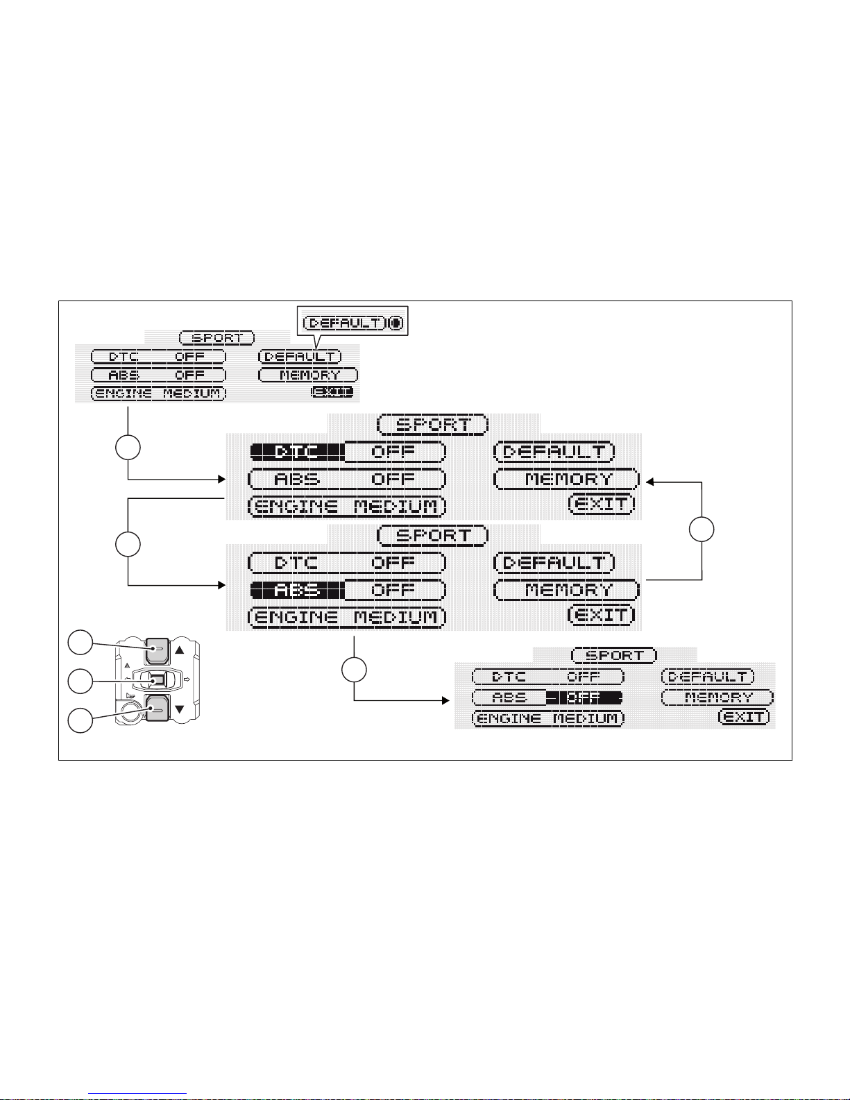
To customise parameters, select the riding mode you
wish to edit and press button (4).
Customisable parameters are DTC (Ducati Traction
Control), ABS (Antilock Braking System) and ENGINE
(engine power).
Use buttons (1) and (2) to select the parameter you
wish to customise.
All edited (customised) parameters are stored inside
memory even after a Battery-Off.
The parameters of a single riding mode can also be
reset through the DEFAULT function.
Note
If on DEFAULT lettering right side a symbol is
displayed, this means that the default setup is active,
namely that the parameters shown are those set up
by Ducati.
Warning
Changes should only be made to the
parameters by people who are experts in motorcycle
set-up; if the parameters are changed accidentally,
use the "DEFAULT" function to restore factory
settings.
63
Page 65
1
2
4
4
2
1
1
Fig. 38
64
Page 66

DTC set up
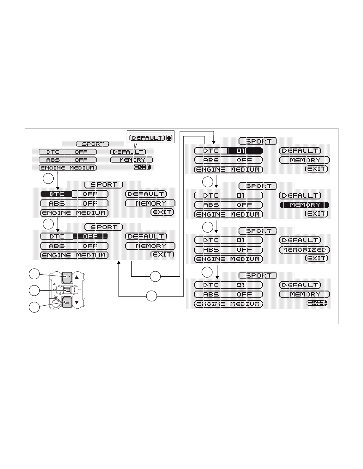
This function allows customising DTC (Ducati
Traction Control) intervention level and, if necessary,
disabling it.
To display this function, access the Setting Menu and
select the R.MODE page.
Use buttons (1) and (2) to select the riding mode you
wish to edit, then press button (4).
Use keys (1) and (2) to select the DTC indicator, then
press button (4) to access the setup page.
Now, always using buttons (1) and (2), you can
increase or decrease DTC level; press button (4) to
confirm the new level.
The different settings are 01, 08 and OFF.
Note
If OFF is set, the DTC will be disabled.
Once the new setup is selected, press button (4).
The instrument panel will automatically highlight the
"MEMORY" indicator; to store the new setup, keep
button (4) pressed for 3 seconds. After this time, the
instrument panel will display the "MEMORIZED"
indicator for 2 seconds as a confirmation of the
change made.
The "EXIT" indicator will be automatically highlighted;
press button (4) to quit this page and go back to the
setting menu.
Note
If on DEFAULT lettering right side a symbol is
displayed, this means that the default setup is active,
namely that the parameters shown are those set up
by Ducati.
65
Page 67
1
2
4
1
4
4
4
1
1
2
Fig. 39
66
Page 68
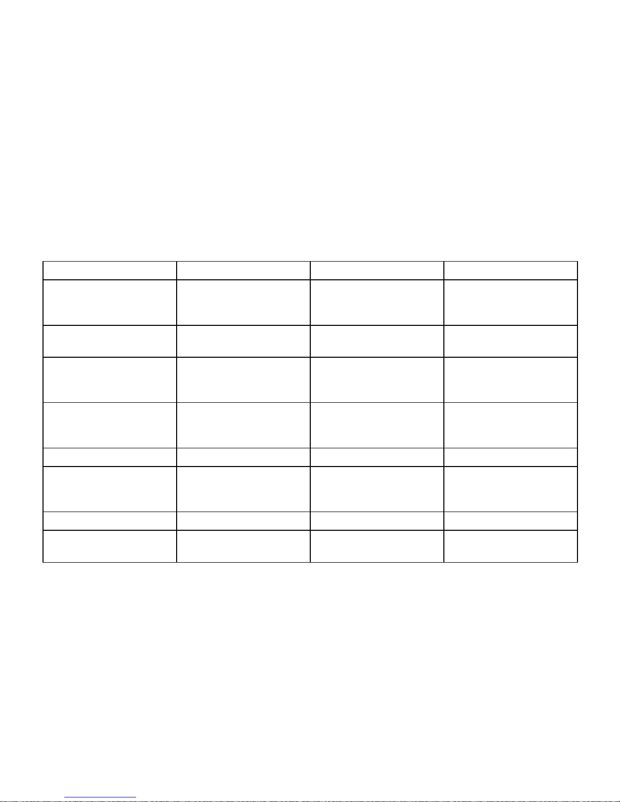
The following table indicates the most suitable level of DTC intervention for the various riding types as well
as the default settings in the "Riding Mode" that can be selected by the rider:
DTC LEVEL RIDING MODE USE DEFAULT?
1 TRACK Professional Track use for very experi-
enced riders. System permits sliding sideways.
NO
2 TRACK Track use (and road use
for expert riders).
NO
3 SPORT Sports use both on the
road and on the track.
It is the default level for
the “SPORT” Riding
Mode
4 TOURING Touring extra-urban use. It is the default level for
the “TOURING” Riding
Mode
5 CRUISE Cruise touring use. NO
6 URBAN Urban use. It is the default level for
the “URBAN” Riding
Mode
7 RAIN Wet or moist road. NO
8 HEAVY RAIN Wet road with heavy rain
or very slippery asphalt.
NO
67
Page 69
Tips on how to select the sensitivity level
Warning
The 8 levels of the DTC system your motorcycle
is equipped with were calibrated with original
equipment tyres (make, model and size). The use of
tyres of different size to the original tyres may alter
the operating characteristics of the system.
Motorbike original equipment: (front 120/70ZR17 rear 180/55ZR17).
- Pirelli Diablo Supercorsa SP;
- Pirelli Diablo Rosso II;
- Pirelli Scorpion Trail.
In the case of minor differences, such as for example,
tyres of a different make and/or model than the OE
ones, but with the same size (rear = 180/55-17; front
= 120/70-17), it may be sufficient to simply select the
most suitable level setting from those available to
restore optimal system operation. If tyres of a
different size class are used or if the tyre size differs
significantly from the original tyres, it may be that the
system operation is affected so much that none of
the 8 available level settings will give satisfactory
results. In this case is it is advisable to deactivate the
traction control system. If level 8 is selected, the DTC
control unit will kick in at the slightest hint that the
rear wheel is starting to spin. Between level 8 and
level 1 there are a further 8 intermediate levels. The
level of DTC intervention decreases in equal steps
from level 8 to 1. When level 1 or 2 is selected, the
DTC control unit will allow the rear wheel to spin and
also slide sideways on exiting a corner; we
recommend that this setting is only used on the track
and by very experienced riders.
The choice of the correct level depends on 3 main
variables:
1) The grip (type of tyre, amount of tyre wear, the
road/track surface, weather conditions, etc.);
2) The characteristics of the path/circuit (bends all
taken at similar speeds or at very different
speeds);
3) The riding mode (whether the rider has a
“smooth” or a “rough” style).
Relation of the DTC intervention level to grip
conditions
68
Page 70

The choice of level setting depends greatly on the
grip conditions of the track/circuit (see below, tips for
use on the track and on the road).
Relation of the DTC intervention level to the path
characteristics
If all the corners on the track/circuit can be taken at a
similar speed, it will be easier to find an intervention
level that is satisfactory for every bend; on the other
hand, if the track has, for example, one corner that is
much slower than all the others, it will be necessary
to find a compromise level (on the slow corner the
DTC will tend to kick in more than on the faster
corners).
Relation of the DTC intervention level to the riding
mode
The DTC will tend to kick in more with a “smooth”
riding style, where the bike is leaned over further,
rather than with a “rough” style, where the bike is
straightened up as quickly as possible when exiting a
turn.
Tips for use on the track
We recommend that level 6 is used for a couple of
full laps (to allow the tyres to warm up) in order to get
used to the system. Then try levels 5, 4, etc., in
succession until you identify the DTC sensitivity level
that suits you best (always try each level for at least
two laps to allow the tyres to warm up).
Once you have found a satisfactory setting for all the
corners except one or two slow ones, where the
system tends to kick in and control too much, you can
try to modify your riding mode slightly to a more
“rough” approach to cornering i.e. straighten up
more rapidly on exiting the corner, instead of
immediately trying a different level setting.
Tips for use on the road
Activate the DTC, select DTC 6 and ride the
motorcycle in your usual style; if the DTC intervention
level seems excessive, try DTC 5; if also this RM is
too strong, try DTC 4. If none of the available level
settings meets your riding style, you can select the
level by following the indications given in the table
above until you find the level that suits you best.
If changes occur in the grip conditions and/or circuit
characteristics and/or your riding style, and the level
setting is no longer suitable, switch to the next level
up or down and proceed to determine the best
setting (e.g. if with level 7 the DTC intervention
seems excessive, switch to level 6; alternatively, if on
69
Page 71

level 7 you cannot perceive any DTC intervention,
switch to level 8).
70
Page 72

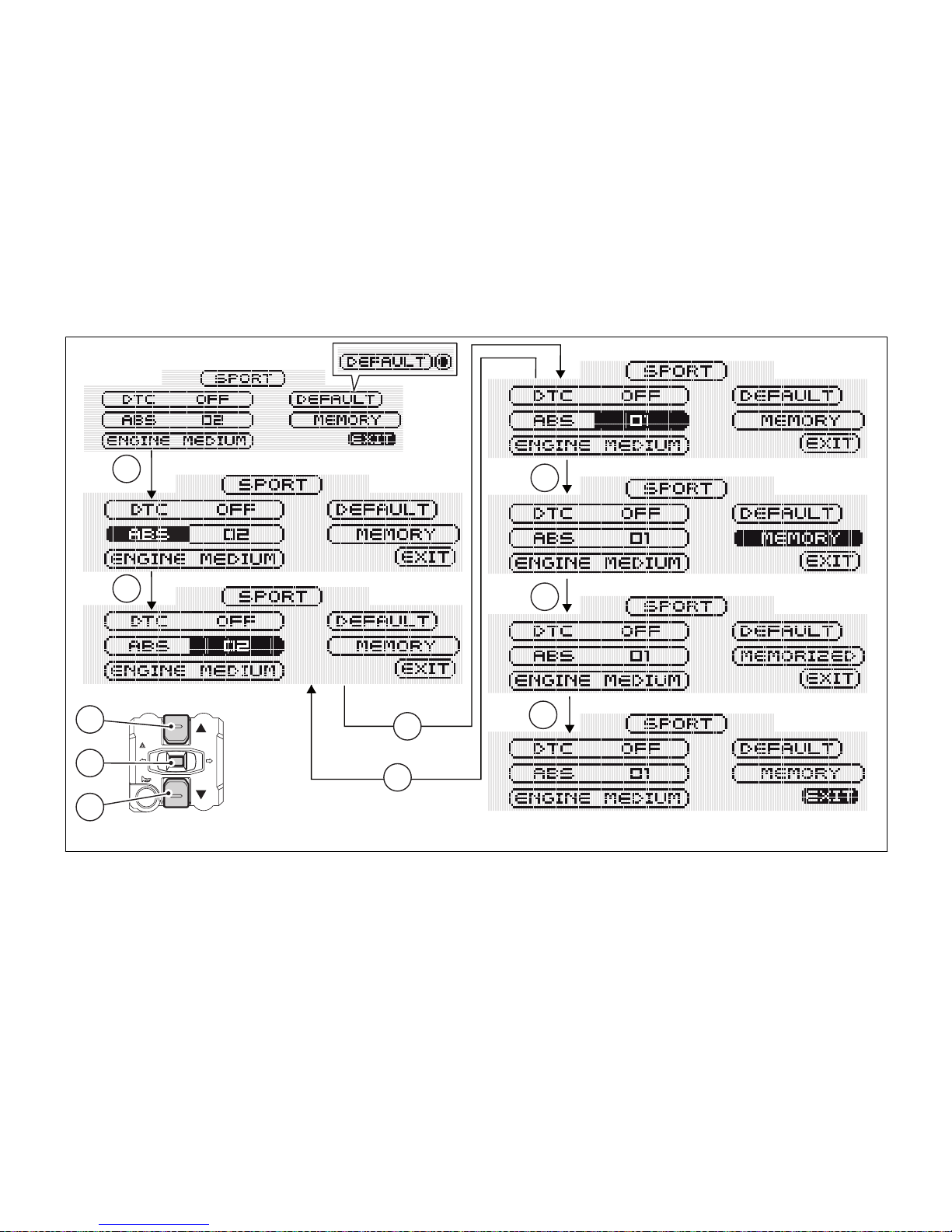
ABS set up
This function allows customising ABS (Antilock
Braking System) intervention level and, if necessary,
disabling it. To display this function, access the
Setting Menu and select the R.MODE page.
Use buttons (1) and (2) to select the riding mode you
wish to edit, then press button (4). Use keys (1) and
(2) to select the ABS indicator, then press button (4)
to access the setup page. Now, always using buttons
(1) and (2), you can increase or decrease ABS level;
press button (4) to confirm the new level.
The different settings are 01, 02 and OFF.
Note
If OFF is set, the ABS will be disabled and the
corresponding ABS warning light will start flashing.
Once the new setup is selected, press button (4). The
instrument panel will automatically highlight the
"MEMORY" indicator; to store the new setup, keep
button (4) pressed for 3 seconds;
After this time, the instrument panel will display the
"MEMORIZED" indicator for 2 seconds as a
confirmation of the change made. The "EXIT" indicator
will be automatically highlighted; press button (4) to
quit this page and go back to the setting menu.
Note
If ABS OFF is selected and stored, Ducati
recommends paying the utmost attention while
riding and braking your bike.
Note
If on DEFAULT lettering right side a symbol is
displayed, this means that the default setup is active,
namely that the parameters shown are those set up
by Ducati.
71
Page 73
1
2
4
1
4
4
4
1
1
2
Fig. 40
72
Page 74

The following table indicates the most suitable level of ABS intervention for the various riding types as well
as the default settings in the "Riding Mode" that can be selected by the rider:
LEVEL MODE USE DEFAULT?
OFF The ABS is disabled. NO
1 SPORT For road use in good grip conditions. Under this
mode, ABS is active on both wheels. Lift-up prevention controls are active; this calibration favours
braking power and ensures, at the same time,
good stability levels during braking and lift-up control*.
It is the default level
for the "SPORT" and
“TOURING” Riding
Modes.
2 URBAN For use under any riding condition. Under this
mode, ABS is active on both wheels. This calibration favours vehicle max. stability and lift-up prevention and ensures, at the same time, a top level
max. deceleration performance.
It is the default level
for the “URBAN”
Riding Mode.
73
Page 75
Tips on how to select the sensitivity level
Warning
The levels of the ABS system your motorcycle
is equipped with were calibrated with original
equipment tyres.
The use of tyres of different size and characteristics
to the original tyres may alter the operating
characteristics of the system thus making it unsafe.
It is recommended not to install tyres of different size
than the ones approved for your vehicle.
Motorbike original equipment: (front 120/70ZR17 rear 180/55ZR17).
- Pirelli Diablo Supercorsa SP;
- Pirelli Diablo Rosso II;
- Pirelli Scorpion Trail.
If level 2 is selected, the ABS system will be activated
to ensure a very stable braking and a good bike
control as well as to prevent any lift-up, thus allowing
a good vehicle alignment during the whole braking
action. When shifting from level 2 to level 1, braking
power will be favoured compared to max. stability
control and lift-up prevention, which is nevertheless
still active.
The choice of the correct level mainly depends on the
following parameters:
1) Tyre/road grip conditions (type of tyre, amount of
tyre wear, the road/track surface, weather
conditions, etc.).
2) Rider experience and skill.
Under poor grip conditions (see point 1) and/or for
less experienced riders, we recommend using level
2.
74
Page 76

ENGINE set up
This function allows customising ENGINE power and
output.
To display this function, access the Setting Menu and
select the "R.MODE" page. Use buttons (1) and (2) to
select the riding mode you wish to edit, then press
button (4).
Use buttons (1) and (2) to select the "ENGINE"
indicator, then press button (4) to access the setup
page.
Now, always using buttons (1) and (2), you can
increase or decrease ENGINE level; press button (4)
to confirm the new level.
The different settings are HIGH, MEDIUM and LOW.
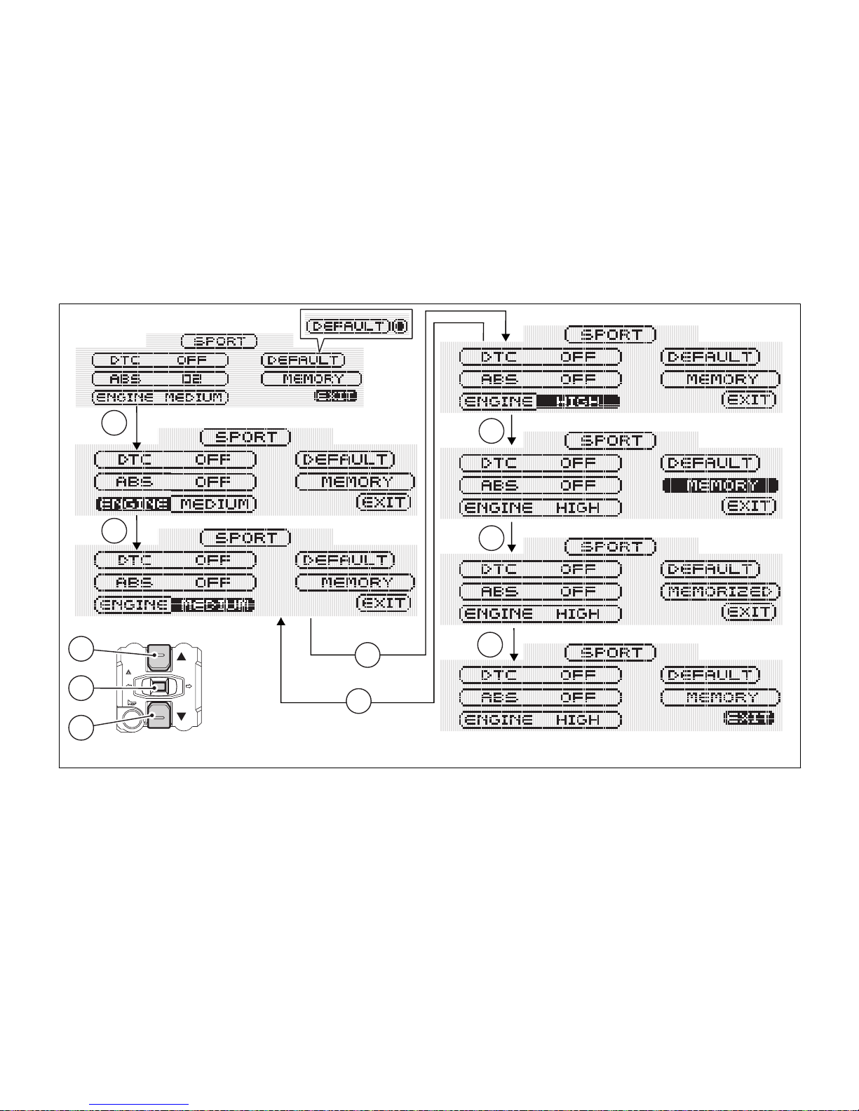
Once the new setup is selected, press button (4). The
instrument panel will automatically highlight the
"MEMORY" indicator; to store the new setup, keep
button (4) pressed for 3 seconds.
After this time, the instrument panel will display the
"MEMORIZED" indicator for 2 seconds as a
confirmation of the change made. The "EXIT" indicator
will be automatically highlighted; press button (4) to
quit this page and go back to the setting menu.
Note
If on DEFAULT lettering right side a symbol is
displayed, this means that the default setup is active,
namely that the parameters shown are those set up
by Ducati.
75
Page 77
1
2
4
1
4
4
4
1
1
2
Fig. 41
76
Page 78

ALL DEFAULT (Resetting the default
parameters of all Riding Modes)
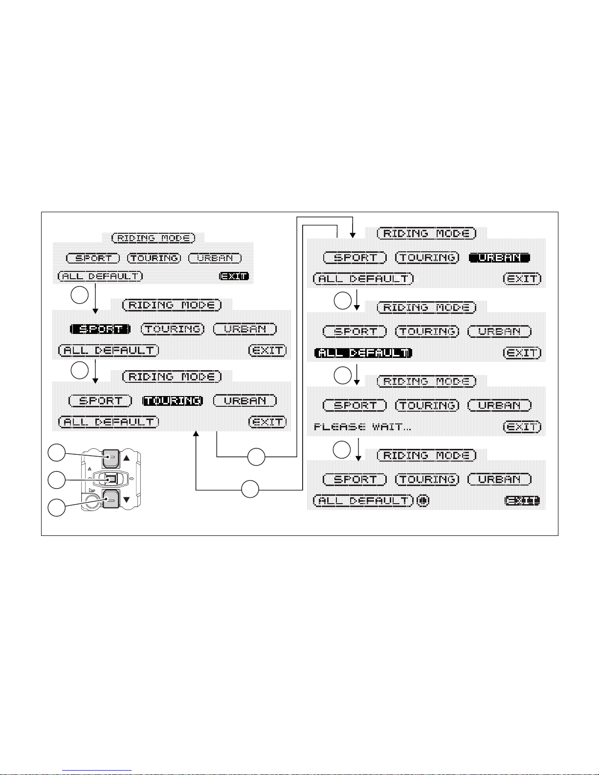
This function allows restoring all Ducati setup
parameters for SPORT, TOURING and URBAN Riding
Modes.
To display this function, access the Setting Menu and
select the "R.MODE" page.
Use buttons (1) and (2) to select the "ALL DEFAULT"
indicator, then keep button (4) pressed for 3 seconds.
Now the "ALL DEFAULT" wording will be replaced by
the "PLEASE WAIT..." indicator, which will be
displayed for 3 seconds to inform the user that the
instrument panel is restoring the default parameters
for all Riding Modes.
After this time (3 seconds), the "EXIT" indicator will be
automatically highlighted; press button (4) to quit this
page and go back to the setting menu.
Note
If on ALL DEFAULT lettering right side a symbol
is displayed, this means that the default setup is
active, namely that the parameters shown are those
set up by Ducati.
77
Page 79
1
2
4
1
1
4
4
1
1
2
Fig. 42
78
Page 80

DEFAULT (Resetting the default
parameters of a single Riding Mode)
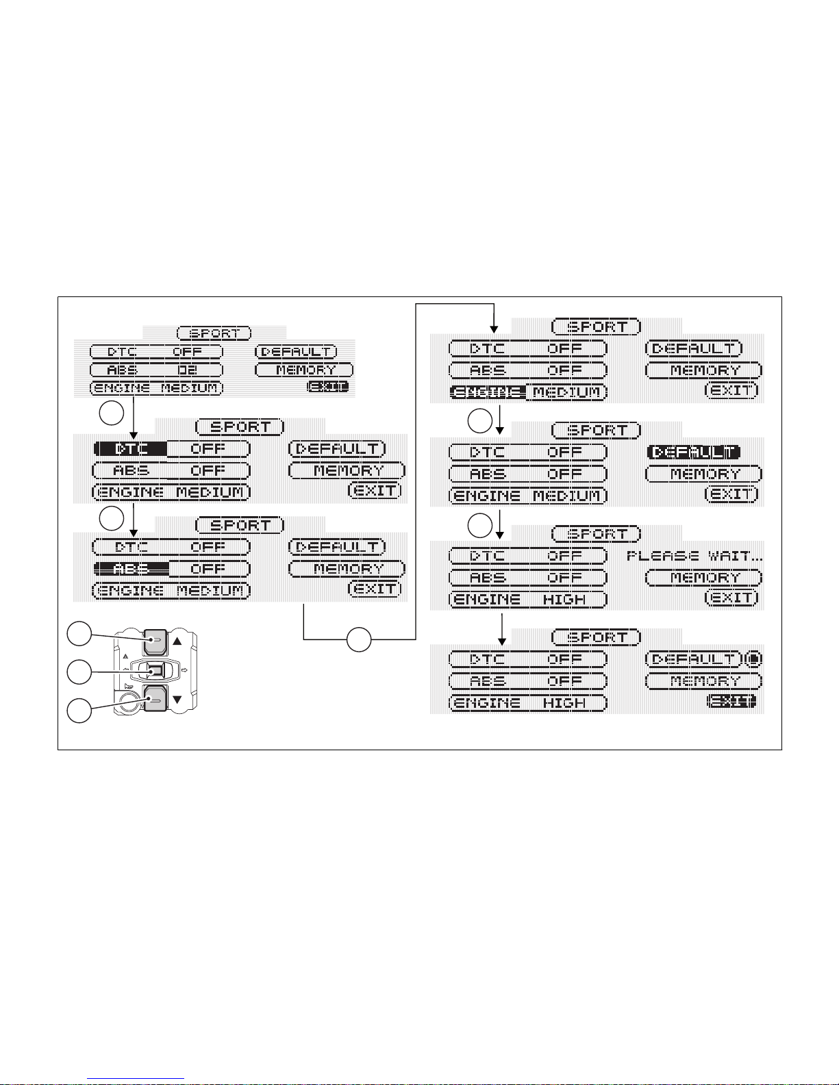
This function allows restoring all Ducati setup
parameters for a single Riding Mode.
To display this function, access the Setting Menu and
select the "R.MODE" page.
Use buttons (1) and (2) to select the riding mode for
which you wish to restore the default parameters,
then press button (4). Use buttons (1) and (2) to select
the "DEFAULT" indicator, then keep button (4)
pressed for 3 seconds.
Now the "ALL DEFAULT" wording will be replaced by
the "PLEASE WAIT..." indicator, which will be
displayed for 3 seconds to inform the user that the
instrument panel is restoring the default parameters
for the selected Riding Mode.
After this time (3 seconds), the "EXIT" indicator will be
automatically highlighted; press button (4) to quit this
page and go back to the setting menu.
Note
When the default settings are active, a symbol
(circle with a dot) is always displayed close to the
DEFAULT indicator.
79
Page 81
1
2
4
1
1
1
4
1
Fig. 43
80
Page 82

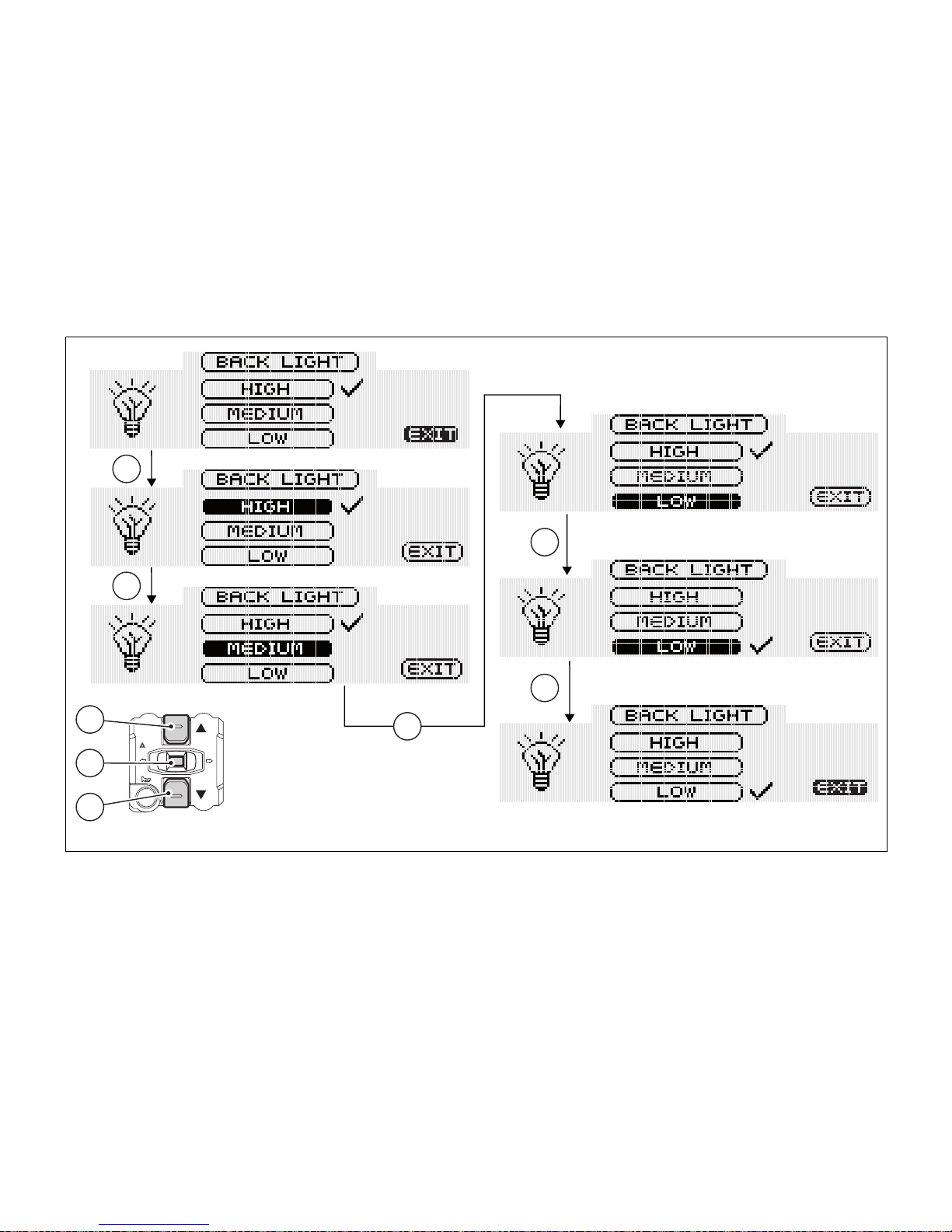
Dashboard backlighting setting function
(B.LIGHT)
This function allows dashboard backlighting setting.
To display this function, access the Setting Menu and
select the "B.LIGHT" page.
The information will be displayed as follows:
- the tick (V) indicates that the setting is currently
enabled;
- use buttons (1) and (2) to highlight the new
setting;
- to store the new setting, press button (4); the tick
(V) will move on the stored condition.
To quit this page, highlight the "EXIT" wording, and
press button (4).
1) HIGH setting: when this condition is stored,
backlighting is at the max. level.
2) MEDIUM setting: when this condition is stored,
backlighting is reduced by approx. 30%
compared to max. level.
3) LOW setting: when this condition is stored,
backlighting is reduced by approx. 70%
compared to max. level.
Note
In the event of an interruption of the power
supply from the battery, when power is restored at
the next Key-On, the backlighting will always be set
by default to maximum brightness.
81
Page 83
1
2
4
1
1
4
1
1
Fig. 44
82
Page 84

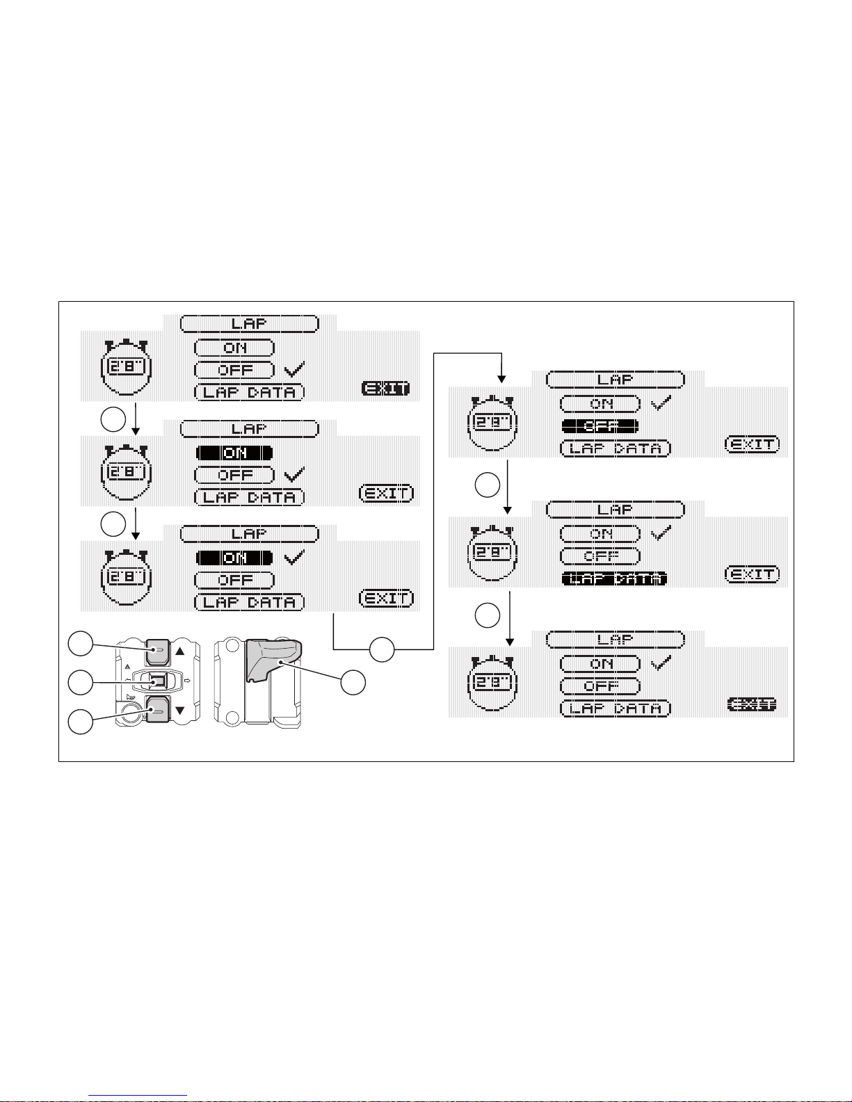
Lap time function (LAP): LAP activation/
deactivation
This function activates and deactivates the LAP
function (lap time).
To display this function, access the Setting Menu and
select the "LAP" page.
The information will be displayed as follows:
- the tick (V) indicates that the setting is currently
enabled;
- use buttons (1) and (2) to highlight the new
setting;
- to store the new setting, press button (4); the tick
(V) will move on the stored condition.
To quit this page, select the "EXIT" wording, and press
button (4). Storing the "OFF" condition disables the
LAP function.
Storing the "ON" condition enables the LAP function.
Note
When the LAP function is enabled, button (3)
can be used both as high beam Flash and lap time
Start/Stop.
83
Page 85
1
2
4 3
1
4
1
1
1
Fig. 45
84
Page 86

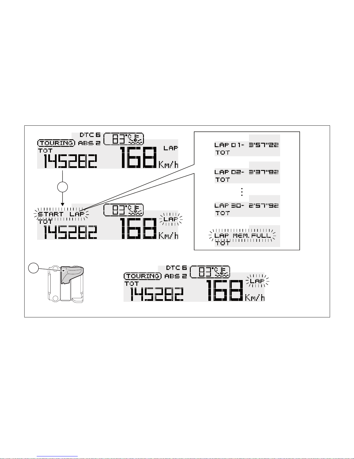
This function is used to describe how lap times (LAP)
are stored.
If function is enabled, lap time can be stored as
follows:
- after the first time you press button (3) the first
lap counter is started and the instrument panel
displays the "START LAP" indicator (flashing) for
4 seconds, before reverting to previous display;
- from now on, each time you press button (3), the
instrument panel will show the lap time for 10
seconds (steady), before reverting to the
previous display.
Up to 30 lap times can be stored. If the memory is
full, each time you press button (3), the instrument
panel will not be able to save any lap time and, for 4
seconds, the display will show the message “LAP
MEM. FULL" (flashing) until the memory is reset.
When the LAP function is set to Off, the current lap
is not stored. If the LAP function is active and the
display is suddenly switched off (Key-Off), the LAP
function is switched off automatically: even if the
timer was ON, the lap in progress will not be saved.
If the timer is not stopped, when it reaches 9
minutes, 59 seconds and 99 hundredths, it restarts
from 0 (zero) and continues until the function is
switched off.
If the LAP function is enabled without resetting the
memory and there are less than 30 laps stored in the
memory (for instance: 18 laps), the instrument panel
will store any remaining laps until the memory is full
(in this case, it will store an additional 12 laps).
This function only displays lap times being stored;
however, other data (MAX Speed, RPM MAX, rev
limiter - if tripped) are saved for a subsequent
complete display in the LAP displaying function.
85
Lap time function (LAP): LAP registration
Page 87
3
3
Fig. 46
86
Page 88
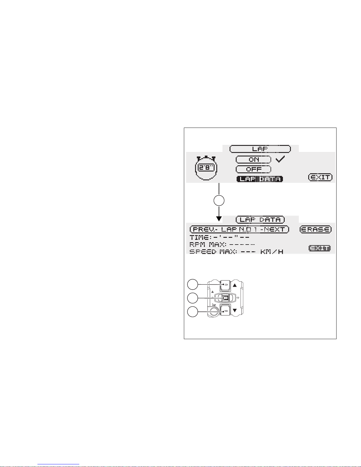
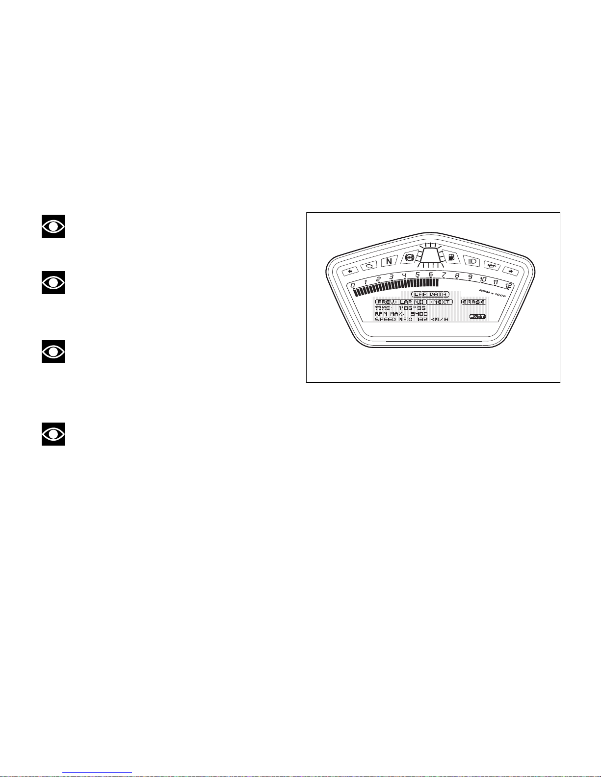
This function displays the stored LAPs. To display this
function, access the Setting Menu and select the LAP
page. Use buttons (1) and (2) to highlight the "LAP
DATA" indicator, then press button (4).
The instrument panel will display the information as
follows:
- lap number being displayed (example: No.1);
- NEXT indicator to view next LAP;
- ERASE indicator to delete all stored lap times;
- TIME: and then lap time (example: 1’50’’97);
- RPM MAX: max. engine RPM reached during the
stored LAP;
- SPEED MAX: max. speed reached during the
stored LAP.
To quit this page, select the "EXIT" wording, and press
button (4).
4
1
2
4
Fig. 47
87
LAP time function: Stored LAPs displaying
Page 89
Note
The MAX stored speed is reached during lap
(increased by 5%).
Note
If MAX speed reading exceeds 299 km/h (186
mph) while the information is stored, speed reading
is displayed (example: 316 km/h).
Note
If no lap times are saved in memory, the 30 lap
times will be displayed as 0’00’’00, the RPM max.
number equal to 0 (zero) and the MAX speed value
equal to 0 (zero).
Note
If the engine trips the threshold before the rev
limiter kicks in or makes the rev limiter kick in during
lap saving, the corresponding Over Rev light will
come on during the displaying of the stored lap times.
Fig. 48
88
Page 90

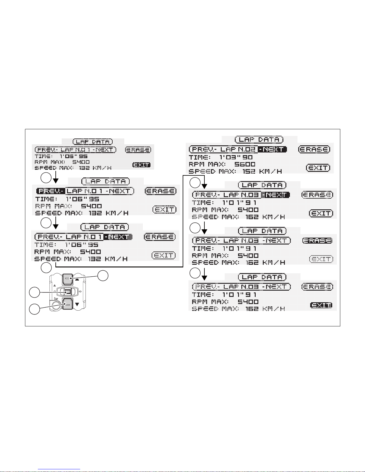
To display other stored lap times, press buttons (1)
and (2) to highlight NEXT (or PREV), then press button
(4); each time you press button (4) the next lap will be
displayed.
To erase all stored lap times, highlight the ERASE
indicator and keep button (4) pressed for 3 seconds.
Note
If the stored times are deleted while the LAP
function is active, it will be automatically deactivated.
89
Page 91
1
2
4
2
1
4
1
4
4
Fig. 49
90
Page 92

Clock setting function (CLOCK)
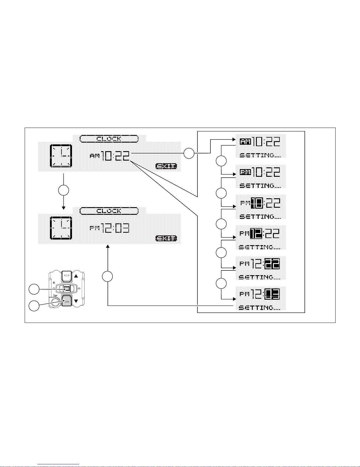
This function allows setting the clock. To display this
function, access the Setting Menu and select the
"CLOCK" page. To access the setting page, keep
button (4) pressed for 3 seconds. After this time, the
"SETTING..." indicator will be enabled to confirm that
the setting page is active.
On entering this mode, the message “AM” will flash;
- press button (2): PM will start flashing;
- if you press button (2), the mode will go back to
previous setting (if it is 00:00, when toggling from
AM to PM, 12:00 will be displayed).
Pressing button (4) gives access to the hour setting
mode; hours start to flash;
- each time you press button (2), the count will
increase cyclically in steps of one hour;
- if button (2) is held pressed, the count will
increase cyclically in steps of one hour every
second (when the button is held depressed, the
hours do not flash).
Pressing button (4) gives access to the minutes
setting mode; minutes start to flash;
- each time you press button (2), the count will
increase cyclically in steps of one minute;
- if you hold button (2) pressed, the count will
increase cyclically in steps of 1 minute every
second.
- If button (2) is held depressed for over 5 seconds,
minutes will increase by 1 minute every 100 ms
(while button (2) is held depressed, seconds will
not flash).
To confirm (store) the new time setting, press button
(4). The "EXIT" indicator will be automatically
highlighted; press button (4) to quit this page and go
back to the setting menu.
Note
In case of battery off, when the Voltage is
restored and upon next Key-On, clock will have to be
set again (it will automatically start counting from
00:00).
91
Page 93
3
4
2
4
2
4
2
4
2
4
Fig. 50
92
Page 94
Battery voltage function (BATTERY)
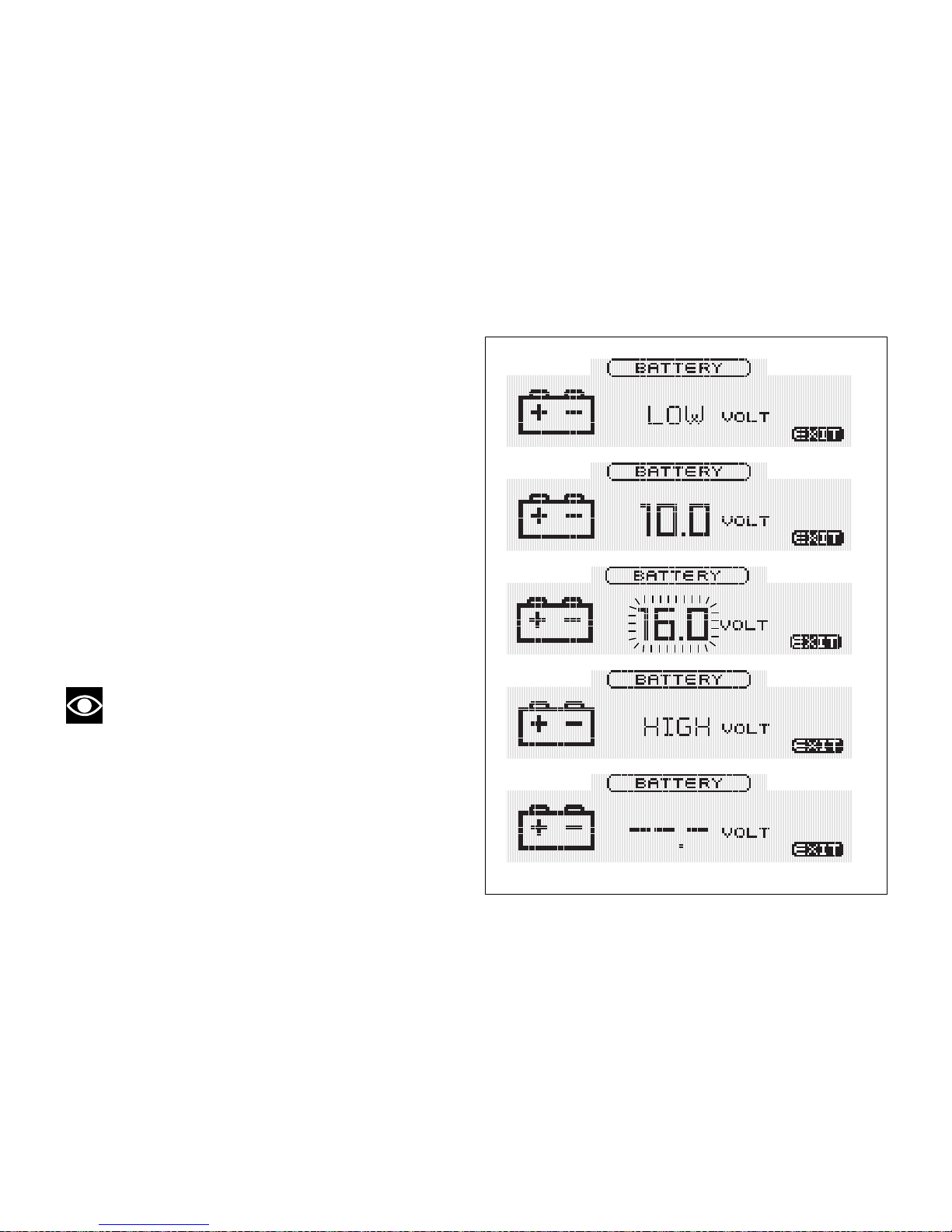
Thanks to this function it is possible to check vehicle
battery condition. To display this function, access the
Setting Menu and select the "BATT" page.
The information will be displayed as follows:
- if battery voltage is between 11.8 and 14.9 Volt
the reading will be displayed steady;
- if battery voltage is between 11.0 and 11.7 Volt
the reading will be displayed flashing;
- if battery voltage is between 15.0 and 16.0 Volt
the reading will be displayed flashing;
- if battery voltage is equal to or less than 10.9 Volt,
"LOW" is shown flashing;
- if battery voltage is equal to or more than 16.1
Volt, "HIGH" is shown flashing;
Note
If the value is not available, a string of dashes "-
- -" will be displayed.
Fig. 51
93
Page 95
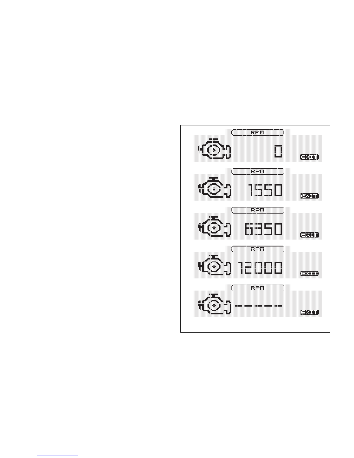
Engine rpm digital indication (RPM)
This function displays the number of RPMs for
improved accuracy when setting idle rpm.
To display this function, access the Setting Menu and
select the "RPM" page.
The display shows the numerical value of the RPM
with a precision of 50 rpm.
Fig. 52
94
Page 96
Immobilizer code (PIN CODE)
This function provides vehicle temporary starting in
the event the Immobilizer system is malfunctioning.
Note
The PIN CODE function must be activated by
the user by entering your 4-digit PIN in the instrument
panel, otherwise the motorcycle cannot be started
temporarily in the case of a malfunction.
To view this function, access the Setting menu, and
press button (4) to enter the "PIN" page.
- If the PIN CODE has not been entered yet, the
"PIN Activation (INSERT NEW PIN)" function will
be displayed.
- If the PIN CODE has already been entered, the
"PIN Editing (MODIFY PIN CODE)" function will
be displayed.
To temporary start the vehicle in the event the
Immobilizer system is malfunctioning, refer to the
"Entering the PIN code to unlock the vehiclepage
105".
Warning
The motorcycle owner must activate (store) the
PIN code; if there is already a stored PIN, contact an
Authorised Ducati Dealer to have the function "reset".
To perform this procedure, the Authorised Ducati
Dealer may ask you to demonstrate that you are the
owner of the motorcycle.
95
Page 97
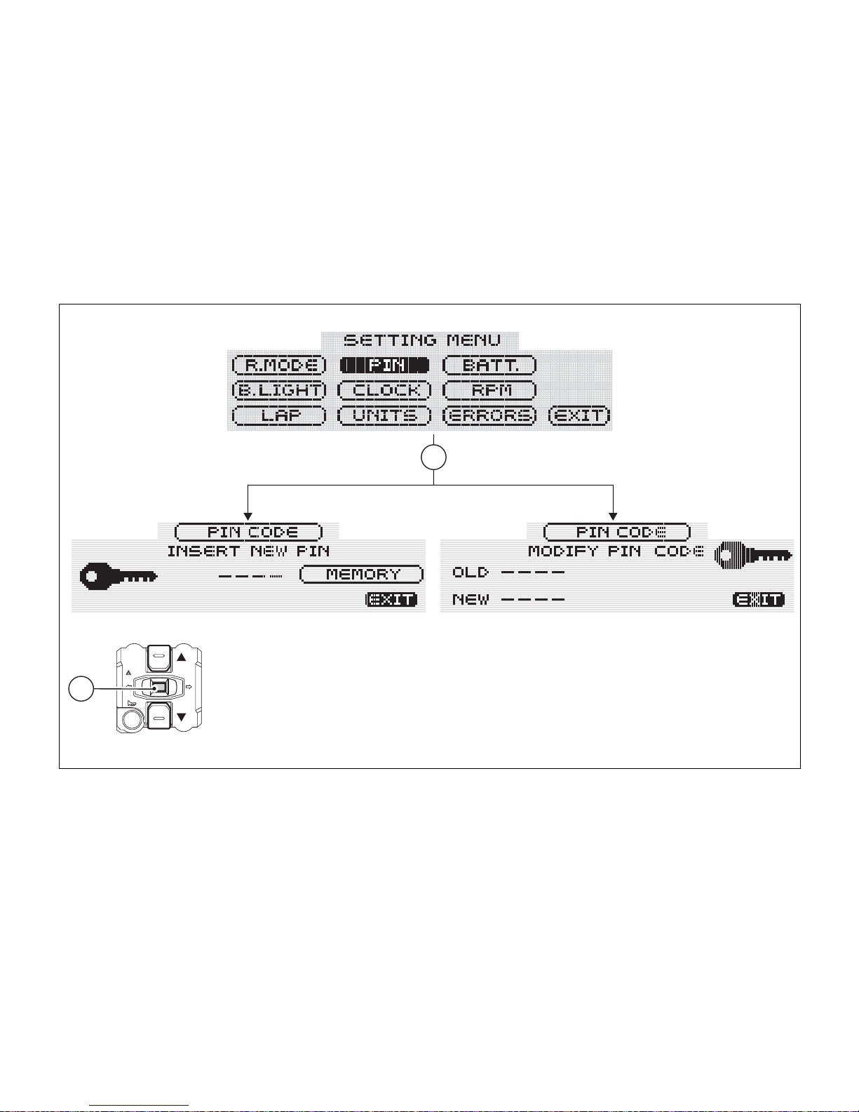
4
4
Fig. 53
96
Page 98
PIN activation
This function allows activating your own PIN CODE
to start the vehicle even if the Immobilizer system is
malfunctioning.
To display this function, access the Setting Menu and
select the "PIN" page.
Note
If "MODIFY PIN CODE" appears when
accessing this function, this means that there is
already a stored PIN and therefore the function is
already active.
When accessing this function, the "INSERT NEW PIN"
indicator and four dashes "- - - -" will be displayed. Now
enter a 4-digit code.
Entering the code:
- each time you press button (2), the highlighted
number increases from 0 to 9 and back to 0,
press button (4) to confirm;
- repeat this procedure until entering the fourth
digit.
- Press button (4) again to confirm.
Once PIN code is entered, the "MEMORY" indicator
will be automatically highlighted.
To store the entered PIN code, keep button (4)
pressed for 3 seconds.
The "MEMORIZED" indicator will be displayed to
confirm that the PIN Code has been stored in the
memory.
From now on, each time the “PIN CODE” function is
accessed, the display will read “MODIFY PIN
CODE”, meaning that the PIN CODE can be
modified.
97
Page 99
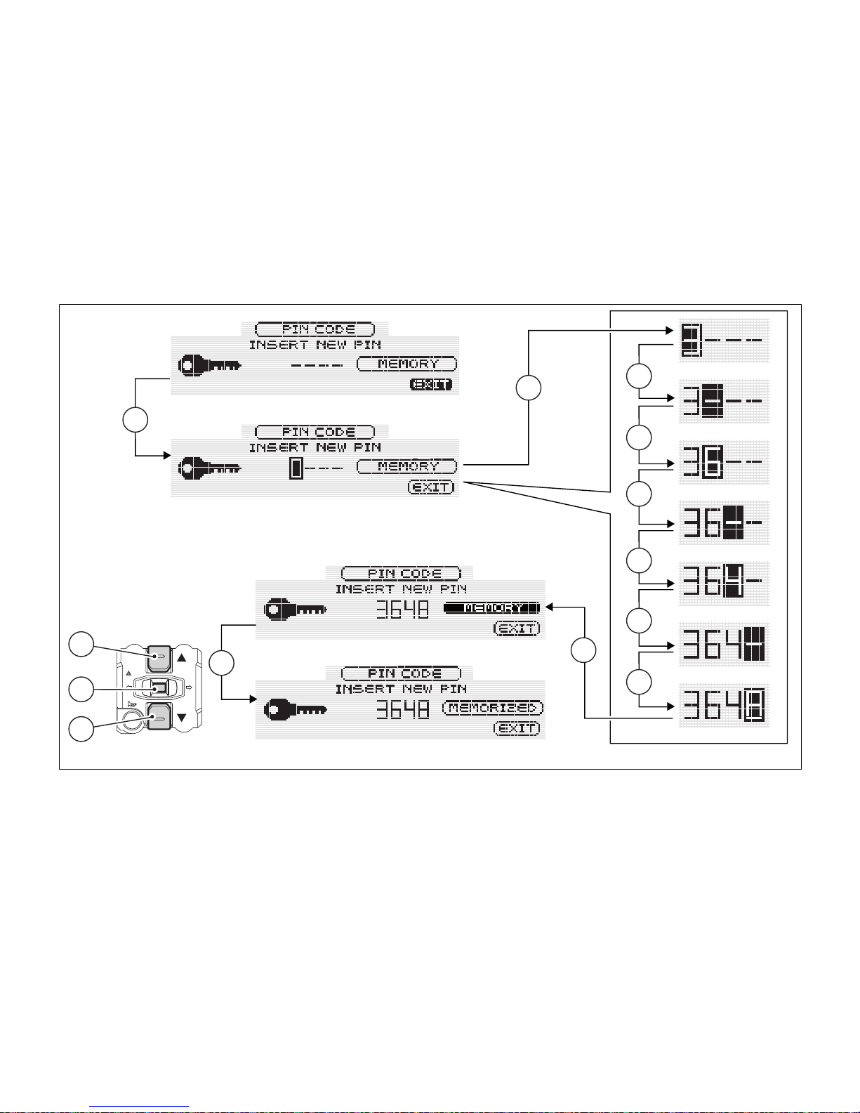
2
2
4
1
4
2
4
2
4
2
2
4
4
Fig. 54
98
Page 100
Changing the PIN CODE
This function changes your four number PIN CODE.
To display this function, access the Setting Menu and
select the "PIN" page.
Note
If, when accessing this function, "INSERT NEW
PIN" and a string of dashes "- - -" are displayed,
function is not active as PIN CODE has never been
entered. Enter your PIN code with the "PIN enabling"
function.
Once function is accessed, the "MODIFY PIN CODE"
indicator will be displayed; press button (1) or (2) to
change the PIN code.
Note
To change the PIN code, you must remember
the already stored PIN.
The "OLD" indicator and four dashes "- - - -" will be
displayed; now enter the old 4-digit PIN number
stored before.
Entering the old PIN code (OLD PIN):
- each time you press button (2), the highlighted
number increases from 0 to 9 and back to 0,
press button (4) to confirm;
- repeat this procedure until entering the fourth
digit.
- Press button (4) again to confirm.
If code is wrong, the "ERROR" indicator (wrong old
code) will be displayed for 3 seconds, then the
instrument panel will display again the "EXIT"
indicator.
If code has been correctly entered, the "CORRECT"
indicator will be displayed, and the first dash will be
highlighted to indicate that it is possible to enter the
new 4-digit code.
99
 Loading...