

Page 1
Page 2

This manual is an integral part of the motorcycle and must remain with it for its entire life.
The manual must accompany the motorcycle if it is sold or transferred to a new owner.
Please store this manual in a safe a place. In case of damage or loss, request a new copy by contacting:
Ducati North America, Inc.
10443 Bandley Drive
Cupertino, California, 95014
Tel: 001.408.253.0499
Fax: 001.408.253.4099
E-mail: customerservice@ducatiusa.com
Web site: www.ducatiusa.com
Quality and safety standards of Ducati motorcycles are constantly being updated consequent to the
development of new design solutions, equipment and accessories. Although the manual includes fully
updated information at the time of print, Ducati Motor Holding S.p.A. therefore reserves the right to make
changes without prior notification or without incurring obligations. For this reason, you may note
discrepancies when comparing some illustrations with your motorcycle.
Any and all reproduction or dissemination of the contents in whole or in part is strictly prohibited. All rights
are reserved by Ducati Motor Holding S.p.A. Requests for authorizations shall be made in writing to this
company with specification of the reason.
Page 3
Owner's manual
US/CANADA
1
Page 4

We'd like to welcome you among Ducati enthusiasts and congratulate you on your excellent choice of
motorcycle. We imagine you'll be riding your Ducati motorcycle for long trips as well as short daily excursions.
Ducati Motor Holding S.p.A. wishes you smooth and enjoyable riding.
Your motorcycle is the result of constant research and development by Ducati Motor Holding S.p.A., so it's
important that the standard of quality is upheld through careful observance of the scheduled maintenance
chart and the use of original spare parts. In the Owner's Manual you'll find instructions for performing small
maintenance procedures. The most important servicing and maintenance procedures are contained in the
Service Manual available at Authorized Service Centers of Ducati Motor Holding S.p.A..
In your own interest, for your safety and in order to guarantee product reliability, we strongly recommend
that you go to an Authorized Dealer or Service Center for any servicing included on the scheduled
maintenance chart (see page 197).
Our highly skilled staff has access to the special tools and equipment needed to perform any servicing
procedure with expertise. They use only Ducati original spare parts as the best guarantee for full
interchangeability, smooth running and long life.
All Ducati motorcycles come with a Warranty Booklet. The Warranty does not extend to motorcycles used
in competitions or competitive trials. Any tampering or even partial modification of the components will result
in automatic invalidation of Warranty rights. Incorrect or insufficient servicing procedures, use of non-original
spare parts or parts not explicitly approved by Ducati may lead to the invalidation of the Warranty, besides
potential damage and reduced performance.
Have fun!
2
Page 5

Table of Contents
Introduction 7
Safety guidelines 7
Warning symbols used in the manual. 7
Permitted use 8
Rider's obligation 8
Reporting of safety defects 10
Rider education 10
Clothing 11
"Best Practices" for safety 12
Refueling 14
Carrying the maximum load allowed 15
Information about carrying capacity 15
Dangerous products - warnings 15
Vehicle ID number 18
Engine ID number 19
Plate positioning 20
Noise and exhaust emission control system
information 24
California emission control warranty statement
Your warranty rights and obligations 25
Manufacturer's warranty coverage 25
Owner's warranty responsibilities: 25
California evaporation emission system 26
Ducati limited warranty on emission control
system 27
Instrument Panel (Dashboard) 30
Instrument panel 30
Technological Dictionary 33
Function pushbuttons 35
LCD unit functions 36
LCD - How to set/display parameters 37
Vehicle speed indicator 39
Engine rpm indicator (RPM) 40
Menu 1 functions 41
Menu 1 functions: Odometer (TOT) 42
Menu 1 functions: Trip meter (TRIP 1) 43
Menu 1 functions: "Trip 2" meter (TRIP 2) 44
Menu 1 functions: Partial fuel reserve counter (TRIP
FUEL) 45
3
Page 6

Menu 1 functions: Average Fuel Consumption
indicator (CONS. AVG) 46
Menu 1 functions: Instantaneous fuel consumption
indicator (CONS.) 47
Menu 1 functions: Average speed indicator (SPEED
AVG) 48
Menu 1 functions: Trip time indicator (TIME
TRIP) 49
Menu 2 functions 50
Menu 2 functions: Coolant temperature 51
Menu 2 functions: Air temperature (AIR) 53
Menu 2 functions: Clock 54
SET UP - Riding Mode set 55
SERVICE function - Maintenance
interventions 56
Active / not active ERRORS indication 59
Indication if the LAP function is active/not
active 60
Riding Mode SET UP function (riding style
change) 61
Error display (ERRORS) 64
SETTING MENU 69
Customizing Riding Modes (R.MODE) 71
DTC set up 75
ABS set up 81
ENGINE set up 85
4
ALL DEFAULT (Resetting the default parameters of
all Riding Modes) 87
DEFAULT (Resetting the default parameters of a
single Riding Mode) 89
Dashboard backlighting setting function
(B.LIGHT) 91
Lap time function (LAP): LAP activation/deactivation
function 93
Lap time function (LAP): LAP registration 95
Funzione Tempo sul giro (LAP): stored LAP
display 97
Clock setting function (CLOCK) 101
Battery voltage function (BATTERY) 103
Engine rpm digital indication (RPM) 104
Immobilizer code (PIN CODE) 105
The Immobilizer system 113
Keys 114
Entering PIN CODE function for vehicle
release 115
Operation 118
Duplicate keys 119
Light control 120
Units of measurement modification function
(UNITS) 123
Other functions 133
Page 7

Controls 135
Position of motorcycle controls 135
Key-operated ignition switch and steering
lock 136
Left-hand switch 137
Clutch lever 138
Right-hand switch 141
Throttle twistgrip 142
Front brake lever 143
Rear brake pedal 144
Gear change pedal 145
Adjusting the position of the gearchange and rear
brake pedals 146
Main components and devices 148
Position on the vehicle 148
Tank filler plug 149
Seat lock 150
Helmet cable 152
Side stand 154
Adjusting the rear shock absorber 155
Riding the motorcycle 157
Break-in recommendations 157
Pre-ride checks 159
ABS 161
Starting the motorcycle 162
Moving off 164
Braking 165
Stopping the motorcycle 167
Parking 168
Refueling 169
Tool kit and accessories 170
Main maintenance operations 171
Check and top up the coolant level 171
Checking brake and clutch fluid level 172
Check brake pads for wear 174
Charge the battery 175
Check drive chain tension 179
Chain lubrication 181
Replace the headlight bulbs 182
Replace the turn indicator bulbs 185
Number plate light 186
Beam setting 187
Adjust rear-view mirrors 189
Tubeless tyres 190
Check engine oil level 192
Clean and replace the spark plugs 194
5
Page 8

Clean the motorcycle 195
Storing the motorcycle 196
Important notes 196
Suspensions 208
Exhaust system 208
Available colors 209
Electrical system 210
Scheduled maintenance chart 197
Scheduled maintenance chart: operations to be
performed by the Dealer 197
Scheduled maintenance chart: operations to be
performed by the customer 200
Technical data 201
Weights 201
Overall dimensions 202
Top-ups 203
Engine 204
Timing system 205
Performance data 206
Spark plugs 206
Fuel system 206
Brakes 206
Transmission 207
Frame 208
Wheels 208
Tires 208
6
Routine maintenance record 216
Routine maintenance record 216
Page 9
Introduction
Attention
Failure to observe these instructions may lead
to a hazardous situation and cause severe injury to
the rider or others, or even death.
Safety guidelines
Your safety and that of others are very important.
Ducati Motor Holding S.p.A. urges you to ride your
motorcycle responsibly.
Before using your motorcycle for the first time,
please read this manual carefully from start to finish
and closely follow the guidelines. This will allow you
to obtain all information regarding a correct use and
maintenance. If you have any doubts or questions,
consult a Dealer or Authorized Service Center.
Warning symbols used in the manual.
Different forms of information regarding potential
hazards that may affect you or others have been
used. These include:
- Safety stickers on the motorcycle;
- Safety warnings preceded by a warning symbol
and by one or the two words Caution or
Important.
Important
Possibility of damaging the motorcycle and/or
its components.
Note
Additional information regarding the job being
performed.
The terms RIGHT and LEFT are referred to the
motorcycle viewed from the riding position.
7
Page 10
Permitted use
This motorcycle may be used on dirt roads or for offroad riding.
Attention
This motorcycle must not be used for towing or
for the addition of a sidecar, since this may cause a
loss or control and consequent accident.
This motorcycle carries the rider and can carry a
passenger.
Attention
The total weight of the motorcycle in running
order with rider, passenger, baggage and additional
accessories must not exceed 895 lb/ 406 kg.
Rider's obligation
All riders must hold a driver's license.
8
Attention
Riding without a license is illegal and punishable
by law. Make sure you always have your license on
you when setting out on the motorcycle. Do not allow
inexpert riders or those not in possession of an
authorized driver's license to ride the motorcycle.
Do not ride the motorcycle when under the influence
of alcohol or drugs.
Attention
Riding under the influence of alcohol or drugs is
illegal and punishable by law.
Avoid taking medication before riding the motorcycle
if you have not consulted your doctor about potential
side effects.
Attention
Some medications may induce sleepiness or
other effects that impair reflexes and the ability of the
rider to control the motorcycle, which may lead to
accident.
Page 11
Some countries require mandatory insurance
coverage.
Attention
Check the laws applicable to your country. Take
out an insurance policy and keep the policy in a safe
place along with the other motorcycle documents.
To protect the safety of the rider and/or passenger,
some countries have made it a law to wear a
homologated helmet.
Attention
Check the laws applicable to your country.
Riding without a helmet may be punishable by a fine.
Attention
Failure to be wearing a helmet in case of
accident increases the chance of serious injury and
even death.
Attention
Make sure that the helmet is in compliance with
safety specifications, provides excellent visibility, is
the correct size for the head, and has the DOT
(Department of Transportation) label affixed to the
helmet surface. Laws regulating traffic vary from
country to country. Check the laws in force in your
country before riding the motorcycle and pay strict
adherence to them .
Attention
Tampering with Noise Control System
Prohibited. Federal Law prohibits the following acts
or causing thereof:
1) the removal or rendering inoperative by any
person, other than for purposes of maintenance,
repair, or replacement, of any device or element
of design incorporated into any new vehicle for
the purpose of noise control prior to its sale or
delivery to the ultimate purchaser or while it is in
use; or
2) the use of the vehicle after such device or
element of design has been removed or
rendered inoperative by any person.
9
Page 12

Among the acts presumed to constitute tampering
are those listed below:
1) Removal of, or puncturing the muffler, baffles,
header pipes or any other component that
conducts exhaust gases.
2) Removal or puncturing of any part of the intake
system.
3) Lack of proper maintenance.
4) Replacing any moving part of the vehicle, or parts
of the exhaust or intake system, with parts other
than those specified by the manufacturer.
This product should be checked for repair or
replacement if the motorcycle noise has increased
significantly through use. Otherwise, the owner may
become subject to penalties under state and local
ordinances.
Reporting of safety defects
If you believe that your vehicle has a defect which
could cause a crash or could cause injury or death,
you should immediately inform the National Highway
Traffic Safety Administration (NHTSA) in addition to
notifying Ducati North America, 10443 Bandley Drive
Cupertino, California, 95014, Tel: 001.408.253.0499,
Fax: 001.408.253.4099. If NHTSA receives similar
10
complaints, it may open an investigation, and if it
finds that a safety defect exists in a group of vehicles,
it may order a recall and remedy campaign. However,
NHTSA cannot become involved in individual
problems between you, your dealer, or Ducati North
America. To contact NHTSA, you may either call the
Auto Safety Hotline toll-free at 1-800-424-9393 (or
366-0123 in Washington, D.C. area) or write to:
NHTSA, 1200 New Jersey Avenue SE W43-488,
Washington, D.C. 20590. You can also obtain other
information about motor vehicle safety from the
Hotline.
Rider education
Accidents are frequently due to inexperience. Riding,
maneuvering and or braking are carried out differently
from other vehicles.
Attention
A rider's lack of preparation or an inappropriate
use of the vehicle may result in a loss of control, death
or serious damage.
Be sure you know the "RULES OF THE ROAD",
carefully read and familiarize with the contents of the
M.O.M. (Motorcycle Operator Manual) for
Page 13
information on your State and which can be viewed
on the M.S.F. (Motorcycle Safety Foundation)
website (www.msf-usa.org).
You are strongly recommended to take a riding
course approved by the M.S.F. (Motorcycle Safety
Foundation).
Clothing
Clothing in the use of the motorcycle plays an
important role in safety, as the motorcycle provides
a person no protection from impact in the same way
as an automobile.
Suitable clothing includes: helmet, eye protection,
gloves, boots, long-sleeved jacket and long pants.
- The helmet must have the requirements listed in
page 8; if your helmet does not have a visor, use
suitable eye wear;
- Gloves must have five fingers and be made of
leather or other abrasion-resistant material;
- Boots or shoes used for riding must have non-slip
soles and ankle protection;
- Jacket and pants, or even riding suits, must be
made of leather or abrasion-resistant material
and in a color with inserts that are very visible.
Important
In any case, avoid wearing loose or floppy
clothing that can become stuck in the motorcycle
parts.
Important
For your safety this type of clothing must be
used in both summer and winter.
Important
For the safety of the passenger, make sure that
he or she also wears appropriate clothing.
11
Page 14
"Best Practices" for safety
Before, during and after use, remember to follow
some simple rules that are extremely important for
safety and for maintaining the motorcycle at top
efficiency.
Important
Closely follow the indications provided in
chapter "Riding the Motorcycle" during the running-in
period.
Failure to follow these instructions releases Ducati
Motor Holding S.p.A. from any liability whatsoever for
any engine damage or shorter engine life.
Attention
Failure to perform checks may cause damage to
the vehicle and serious injury to the rider and/or
passenger.
Attention
Start the engine when outdoors or in a well
ventilated place. Never start the engine in a closed
environment.
Exhaust gases are poisonous and may lead to loss of
consciousness or even death within a short time.
During the ride, assume a correct body position and
make sure the passenger does the same.
Attention
Do not ride the motorcycle unless you are well
familiarized with the controls to be used during the
ride.
Before starting the motorcycle, always performs the
checks detailed in this manual (see page 162).
12
Important
The rider should ALWAYS keep both hands on
the handlebar.
Important
Both rider and passenger should keep their feet
on the footpegs when the motorcycle is in motion.
Page 15
Important
The pillion passenger should always hold on to
the grab handles on the frame under the seat with
both hands.
Important
Be very careful when maneuvering
intersections or when riding in areas near exits from
private grounds, parking lots or access roads to
highways.
Important
Be sure you are clearly visible and do not ride in
the blind spot of the vehicles ahead.
Important
Visually inspect the tires at regular intervals for
cracks and cuts, especially on sidewalls, bulges or
large spots which are indicative of internal damage.
Replace them if badly damaged.
Remove any stones or other foreign bodies caught in
the tread.
Attention
The engine, exhaust pipes and silencers remain
hot for a long time after engine is switched off; pay
particular attention not to touch exhaust system with
any body part and do not park the vehicle next to
inflammable material (wood, leaves etc.).
Important
ALWAYS signal your intention to turn or pull
over to the next lane with due warning using the turn
indicators.
Important
Park your motorcycle where no one is likely to
hit it, and use the side stand. Never park on uneven
or soft ground or your motorcycle may fall over.
Attention
When you leave the motorcycle unattended,
always remove the ignition key and make sure it is
inaccessible to anyone unsuitable to ride the
motorcycle.
13
Page 16
Refueling
Refuel the motorcycle in an open area and with the
engine switched off.
Do not smoke or ever use flames during refueling.
Be careful never to drop fuel on the engine or exhaust
pipe.
When refueling, do not fill the tank completely: fuel
should never be touching the rim of filler recess.
When refueling, avoid inhaling fuel vapors and take
care that they do not come in contact with eyes, skin
or clothing.
Attention
The vehicle is compatible only with fuel having
a maximum content of ethanol of 10% (E10).
Using fuel with ethanol content over 10% is
prohibited. Using it could result in severe damage of
the engine and motorcycle components. Using fuel
with ethanol content over 10% will render the
Warranty null and void.
14
Attention
In case of malaise caused by prolonged
inhalation of fuel vapors, stay outdoors and consult a
physician. In case of contact with eyes, rinse eyes
thoroughly with water. In case of contact with skin,
wash the area immediately with soap and water.
Attention
Fuel is highly flammable. If it accidentally spills
onto clothes, change them.
Page 17
Carrying the maximum load allowed
Your motorcycle is designed for long-distance riding
with the maximum load allowed carried in full safety.
Even weight distribution is critical to preserving these
safety features and avoiding difficulties when
performing sudden maneuvers or riding on bumpy
roads.
Attention
The maximum speed permitted with the side
panniers, top case and the tank bag fitted must not
exceed 111.85 mph (180 km/h).
Attention
Do not exceed the total permitted weight for the
motorcycle and pay attention to the information
below regarding load capacity.
Information about carrying capacity
Important
Arrange your luggage or heavy accessories in
the lowest possible position and close to motorcycle
center.
Important
Never fix bulky or heavy objects to the steering
head or front mudguard, as this would affect stability
and be dangerous.
Important
Be sure to secure the luggage to the supports
provided on the motorcycle as firmly as possible.
Improperly secured luggage may affect stability.
Important
Do not insert any objects you may need to carry
into the gaps of the frame, as these may interfere
with moving parts.
Attention
Make sure tires are inflated to the correct
pressure and that they are in good condition.
Please, refer to paragraph "Tires" in page 190.
Dangerous products - warnings
Used engine oil
15
Page 18
Attention
Prolonged or repeated contact with used engine
oil may cause skin cancer. If exposed to used engine
oil on a daily basis, make it a rule to wash your hands
thoroughly with soap immediately after use. Keep
away from children.
Brake lining debris
Never attempt to clean the brake assembly using
compressed air or a dry brush.
Brake fluid
Attention
The brake fluid used in the brake system is
corrosive. In the event of accidental contact with eyes
or skin, wash the affected area with generous
quantities of running water.
Coolant
Engine coolant contains ethylene glycol, which may
ignite under particular conditions, producing invisible
flames. Although the flames from burning ethylene
glycol are not visible, they are still capable of causing
severe burns.
Attention
Avoid spilling brake fluid onto plastic, rubber or
painted parts of the motorcycle to avoid the risk of
damage. Protect these parts with a clean shop rag
before servicing the motorcycle. Keep away from
children.
16
Attention
Take care not to spill engine coolant on the
exhaust system or engine parts.
These parts may be hot and ignite the coolant, which
will subsequently burn with invisible flames. Coolant
(ethylene glycol) is an irritant and is poisonous when
ingested. Keep away from children. Never remove
the radiator cap when the engine is hot. The coolant
will be scalding hot and is under high pressure.
Page 19

The cooling fan operates automatically: keep hands
well clear and make sure your clothing does not get
caught in the fan.
Battery
Attention
The battery gives off explosive gases; keep it
away from any source of ignition such as sparks,
flames and cigarettes. Charge the battery in a wellventilated area.
17
Page 20
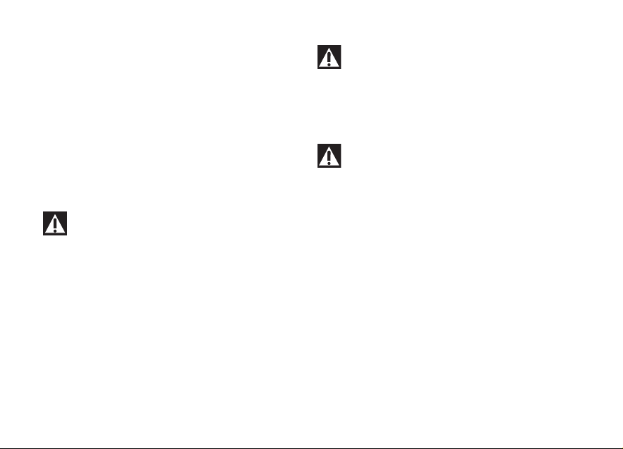
Vehicle ID number
ZDM 1 Y B T S H X B 0 0 0 0 0 0
H Varies-can be thru 9 or X (Check digit)
DUCATI
TYPE OF
MOTORCYCLE
MODEL
YEAR
PLANT OF
MANUFACTURE
SEQUENTIAL
NUMBER
{
{
{
Note
These numbers identify the motorcycle model
and should always be indicated when ordering spare
parts.
We recommend that you note the frame number of
your motorcycle in the space below.
Frame number
Fig 1
18
Fig 2
Page 21
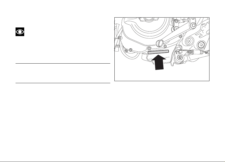
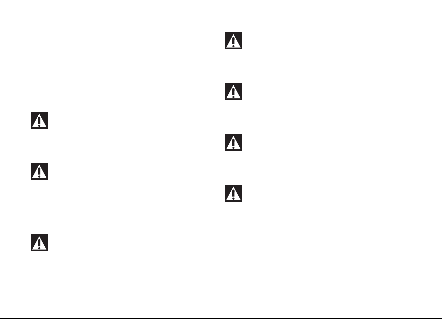
Engine ID number
Note
These numbers identify the motorcycle model
and should always be indicated when ordering spare
parts.
We recommend that you note the engine number of
your motorcycle in the space below.
Engine number.
Fig 3
19
Page 22
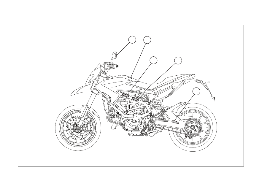
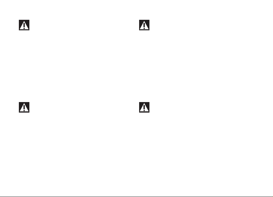
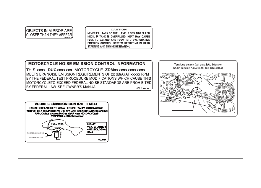
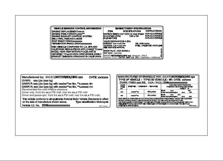
Plate positioning
1
2
3
5
4
20
Fig 4
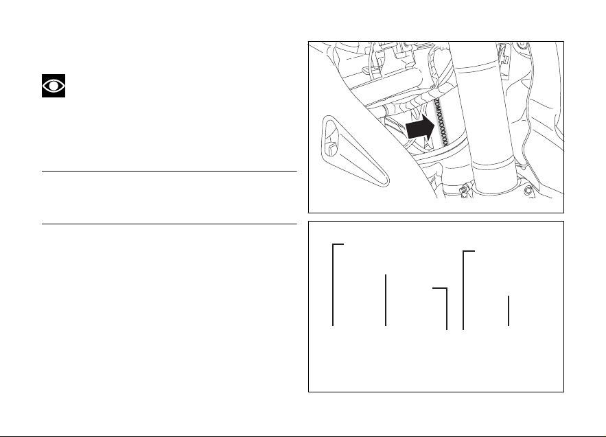
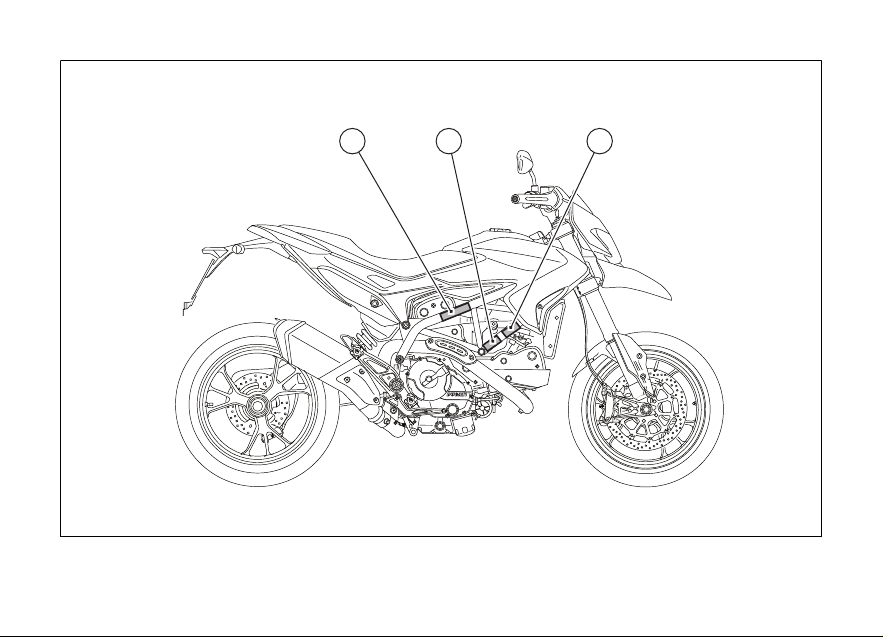
Page 23
5
1
3
2
4
=
=
72 ÷ 74 m m
A
Fig 5
21
Page 24
(only Canada)
6 87
22
Fig 6
Page 25
6
8 (Only Canada)7
Fig 7
23
Page 26

Noise and exhaust emission control system information
Source of Emissions
The combustion process produces carbon monoxide
and hydrocarbons. Control of hydrocarbons is very
important because under certain conditions, they
react to form photochemical smog when subjected
to sunlight.
Carbon monoxide does not react in the same way,
but is toxic. Ducati utilizes lean carburetor settings
and other systems to reduce carbon monoxide and
hydrocarbons.
Exhaust Emission Control System
Exhaust Emission Control System is controlled by an
Electronic Control Unit (ECU), and no adjustments
should be made except idle speed adjustments with
the throttle stop screw. The Exhaust Emission
Control System is separate from the crankcase
emission control system.
Crankcase Emission Control System
The engine is equipped with a closed crankcase
system to prevent discharging crankcase emissions
into the atmosphere. Blow-by gas is returned to the
24
combustion chamber through the air cleaner and the
throttle body.
Evaporative Emission Control System
The motorcycles are equipped with an evaporative
emission control system which consists of a charcoal
canister and associated piping. This system prevents
the escape of fuel vapors from the engine and fuel
tank.
Problems that may affect motorcycle
emissions
If you are aware of any of the following symptoms,
have the vehicle inspected and repaired by your local
Ducati dealer.
Symptoms:
Hard starting or stalling after starting.
Rough idle.
Misfiring or backfiring during acceleration.
After-burning (backfiring).
Poor performance (drivability) and poor economy.
California emission control warranty
statement
Your warranty rights and obligations
Page 27

The California Air Resources Board is pleased to
explain the emission control system warranty on your
MY 2014 motorcycle. In California, new motor
vehicles must be designated, built and equipped to
meet the State's stringent anti-smog standards.
Ducati North America, Inc. must warrant the
emission control system on your motorcycle for the
periods of time listed below provided there has been
no abuse, neglect or improper maintenance of your
motorcycle.
Your emission control system may include parts such
as fuel-injection system, the ignition system, catalytic
converter, and engine computer. Also included may
be hoses, belts, connectors and other emissionrelated assemblies. Where a warrantable condition
exists, Ducati North America, Inc. will repair your
motorcycle at no cost to you including diagnosis,
parts and labor.
Manufacturer's warranty coverage
Manufacturer’s warranty coverage
- 5 years or 30,000 kilometers (18641 miles),
whichever first occurs.
Owner's warranty responsibilities:
- As the motorcycle owner, you are responsible for
the performance of the required maintenance
listed in your owner's manual. Ducati North
America, Inc. recommends that you retain all
receipts covering maintenance on your
motorcycle, but Ducati North America, Inc.
cannot deny warranty solely for the lack of
receipts or for your failure to ensure the
performance of all scheduled maintenance.
- You are responsible for presenting your
motorcycle to a Ducati dealer as soon as a
problem exists. The warranty repairs should be
completed in a reasonable amount of time, not
to exceed 30 days.
- As the motorcycle owner, you should also be
aware that Ducati North America, Inc. may deny
you warranty coverage if your motorcycle or a
part has failed due to abuse, neglect, improper
maintenance or unapproved modifications.
If you have any questions regarding your warranty
rights and responsibilities, you should contact Ducati
North America, Inc. at 001.408.253.0499 or the
California Air Resource Board at 9528 Telstar Avenue,
El Monte, CA 91731.
25
Page 28
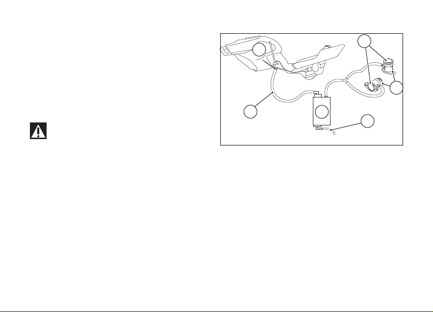
California evaporation emission system
1
3
4
2
6
5
This system consists of:
1) Warn air inlet;
2) Canister;
3) Dell’Orto jet;
4) Fuel tank;
5) Breather pipe;
6) Intake manifolds.
Attention
In the event of a fuel system malfunction,
contact a Ducati Authorized Service Center.
Fig 8
26
Page 29

Ducati limited warranty on emission control system
Ducati North America, Inc., 10443 Bandley Drive
Cupertino, California, 95014 warrants that each new
1998 and later Ducati motorcycle, that includes as
standard equipment a headlight, taillight and
stoplight, and is street legal:
A) is designed, built and equipped so as to conform
at the time of initial retail purchase with all applicable
regulations of the United States Environmental
Protection Agency, and the California Air Resources
Board; and
B) is free from defects in material and workmanship
which cause such motorcycle to fail to conform with
applicable regulations of the United States
Environmental Protection Agency or the California Air
Resources Board for a period of use of 30,000
kilometers (18,641 miles) or 5 (five) years from the
date of initial retail delivery, whichever first occurs.
I. Coverage
Warranty defects shall be remedied during
customary business hours at any authorized Ducati
motorcycle dealer located within the United States of
America in compliance with the Clean Air Act and
applicable regulations of the United States
Environmental Protection Agency and the California
Air Resources Board. Any part or parts replaced under
this warranty shall become the property of Ducati. In
the state of California only, emissions related
warranted parts are specifically defined by that
state’s Emissions Warranty Parts List. These
warranted parts are: carburetor and internal parts;
intake manifold; fuel tank, fuel injection system; spark
advance mechanism; crankcase breather; air cutoff
valves; fuel tank cap for evaporative emission
controlled vehicles; oil filler cap; pressure control
valve; fuel/vapor separator; canister; igniters; breaker
governors; ignition coils; ignition wires; ignition
points, condensers, and spark plugs if failure occurs
prior to the first scheduled replacement, and hoses,
clamps, fittings and tubing used directly in these
parts. Since emission related parts may vary from
model to model, certain models may not contain all
of these parts and certain models may contain
functionally equivalent parts. In the state of California
only, Emission Control System emergency repairs, as
provided for in the California Administrative Code,
may be performed by other than an authorized Ducati
dealer. An emergency situation occurs when an
27
Page 30

authorized Ducati dealer is not reasonably available,
a part is not available within 30 days, or a repair is not
complete within 30 days. Any replacement part can
be used in an emergency repair. Ducati will reimburse
the owner for the expenses, including diagnosis, not
to exceed Ducati’s suggested retail price for all
warranted parts replaced and labor charges based on
Ducati’s recommended time allowance for the
warranty repair and the geographically appropriate
hourly labor rate. The owner may be required to keep
receipts and failed parts in order to receive
compensation.
II. Limitations
This Emission Control System Warranty shall not
cover any of the following:
A. Repair or replacement required as a result of
(1) accident,
(2) misuse,
(3) repairs improperly performed or replacements
improperly installed,
(4) use of replacement parts or accessories not
conforming to Ducati specifications which adversely
affect performance and/or
(5) use in competitive racing or related events.
28
B. Inspections, replacement of parts and other
services and adjustments required for routine
maintenance.
C. Any motorcycle on which odometer mileage has
been changed so that actual mileage cannot be
readily determined.
III. Limited liability
A. The liability of Ducati under this Emission Control
Systems Warranty is limited solely to the remedying
of defects in material or workmanship by an
authorized Ducati motorcycle dealer at its place of
business during customary business hours. This
warranty does not cover inconvenience or loss of use
of the motorcycle or transportation of the motorcycle
to or from the Ducati dealer. Ducati shall not be liable
for any other expenses, loss or damage, whether
direct, incidental, consequential or exemplary arising
in connection with the sale or use of or inability to use
the Ducati motorcycle for any purpose. Some states
do not allow the exclusion or limitation of any
incidental or consequential damages, so the above
limitations may not apply to you. B. No express
emission control system warranty is given by Ducati
except as specifically set forth herein. Any emission
control system warranty implied by law, including any
Page 31

warranty of merchantability or fitness for a particular
purpose, is limited to the express emission control
systems warranty terms stated in this warranty. The
foregoing statements of warranty are exclusive and
in lieu of all other remedies. Some states do not allow
limitations on how long an implied warranty lasts so
the above limitation may not apply to you. C. No
dealer is authorized to modify this Ducati Limited
Emission Control Systems Warranty.
IV. Legal rights
This warranty gives you specific legal rights, and you
may also have other rights which vary from state to
state.
V. This warranty is in addition to the Ducati limited
motorcycle warranty.
VI. Additional information
Any replacement part that is equivalent in
performance and durability may be used in the
performance of any maintenance or repairs.
However, Ducati is not liable for these parts. The
owner is responsible for the performance of all
required maintenance. Such maintenance may be
performed at a service establishment or by any
individual. The warranty period begins on the date the
motorcycle is delivered to an ultimate purchaser.
Ducati North America, Inc..
10443 Bandley Drive
Cupertino, California, 95014
Tel: 001.408.253.0499
Fax: 001.408.253.4099
E-mail: customerservice@ducatiusa.com
Web site: www.ducatiusa.com
29
Page 32

Instrument Panel (Dashboard)
1
2
7
59 6 47 8 3 10
Instrument panel
1) LCD Dot-Matrix.
2) REV COUNTER (rpm).
Indicates engine revs per minute.
3) NEUTRAL LIGHT N (GREEN).
Comes on when in neutral position.
4) HIGH BEAM LIGHT
Turns on to indicate that the high beam lights are on.
5) ENGINE OIL PRESSURE LIGHT
Comes on when engine oil pressure is too low. It
must turn on at Key-On, but must turn off a few
seconds after the engine has started. May come on
briefly when the engine is hot, but should go off as
the engine revs up.
30
(BLUE).
(RED).
Fig 9
Important
If the ENGINE OIL light stays on, stop the
engine or it may suffer severe damage.
Page 33
6) LOW FUEL LIGHT (AMBER YELLOW).
Comes on when fuel is low and there is about a gallon
(4 liters) of fuel left in the tank.
7) TURN INDICATOR LIGHTS (GREEN).
Illuminates and flashes when the turn indicator is in
operation. They both come on and flash when the
Hazard function is in operation
8) “ENGINE/VEHICLE DIAGNOSIS - EOBD” LIGHT
(AMBER YELLOW).
Turns on in case of “engine” and/or “vehicle” errors
and in some cases will lock the engine.
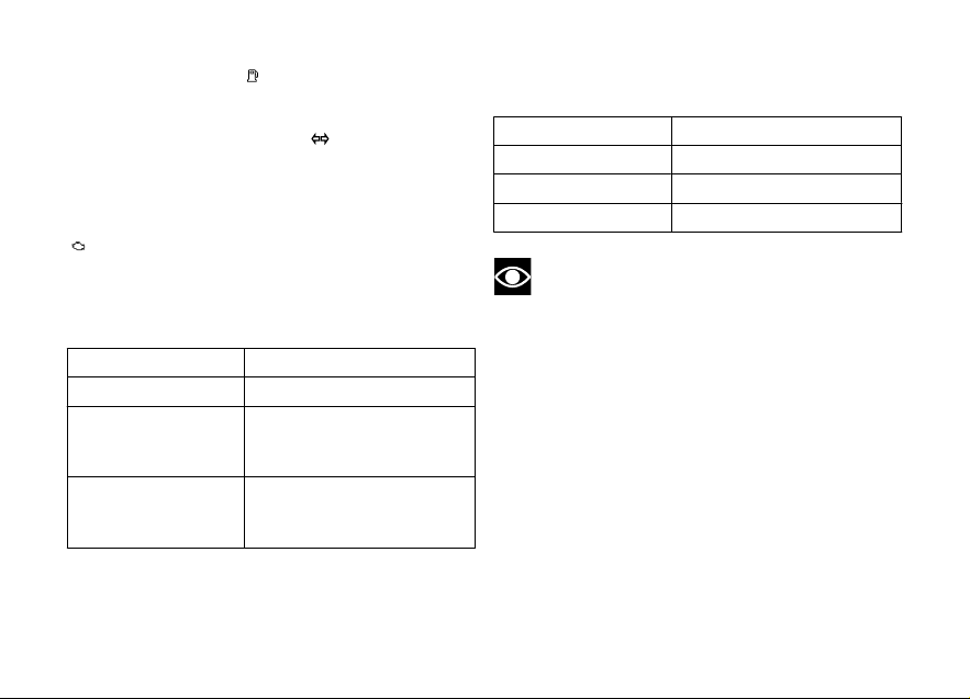
9) LIMITER LIGHT “OVER REV”/ TRACTION
CONTROL LIGHT “DTC” (RED).
Over rev light
No limiter Off
1st threshold - no.
RPM before limiter
kicks in (*)
Rev limiter (limiter engaged due to overrevving) (*)
(*) depending on the model, each calibration of the
Engine Control Unit may have a different "setting" for
On - STEADY
On - Flashing
the thresholds that precede the rev limiter and the rev
limiter itself.
DTC intervention light
No intervention Off
Spark advance cut On - STEADY
Injection cut On - STEADY
Note
If the Over rev function light and the DTC
intervention light should both come on at the same
time, the instrument panel gives priority to the Over
rev function.
31
Page 34
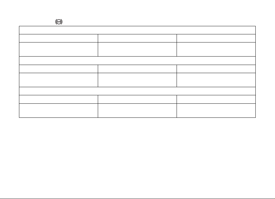
10) ABS LIGHT (AMBER YELLOW) (Fig 9).
Engine off/ speed under 3 mph (5 km/h)
Light off Light flashing Light steady
- ABS disabled with the menu function (**)
Engine on/ speed under 3 mph (5 km/h)
Light off Light flashing Light steady
- ABS disabled with the menu function
Engine on/ speed over 3 mph (5 km/h)
Light off Light flashing Light steady
ABS enabled and functioning ABS disabled with the menu func-
tion
(**) The ABS should be considered actually disabled only if the light continues to flash after starting the
engine.
32
ABS enabled but not functioning
yet
ABS enabled but not functioning
yet
ABS disabled and not functioning
due to problem
Page 35

Technological Dictionary
Acronyms and abbreviations used in the
Manual
ABS
Anti-lock Braking System
BBS
Black Box System
CAN
Controller Area Network
DDA
DUCATI Data Acquisition
DSB
Instrument panel
DTC
DUCATI Traction Control
ECU
Engine Control Unit
Riding Mode
The rider can choose from three different preset bike
configurations (Riding Modes) and pick the one that
best suits his/her riding style or ground conditions.
Riding Modes allow an immediate change of engine
power and output (ENGINE), braking control levels
(ABS) and traction control (DTC) intervention levels.
The available configurations are:
Sport, Touring and Urban (for Hypermotard and
Hyperstrada);
Race, Sport and Wet (for Hypermotard SP).
Within every Riding Mode, the rider can customize
any settings.
Ducati Traction Control (DTC)
The Ducati Traction Control system (DTC) supervises
the rear wheel slipping control and settings vary
through eight different levels that are programmed to
offer a different tolerance level to rear wheel slipping.
Each Riding Mode features a preset intervention
level. Level eight indicates system intervention
whenever a slight slipping is detected, while level one
is for very expert riders because it is less sensitive to
slipping and intervention is thus rarer.
Anti-lock Braking System (ABS)
The ABS system fitted to Hypermotard is a system
that actuates combined braking with anti lift-up
function for the rear wheel so as to guarantee not only
a reduced stopping distance, but also a higher
stability under braking. The ABS features several
levels, one associated to each Riding Mode.
33
Page 36

Ride by Wire (RbW)
The Ride by Wire system is the electronic device that
controls throttle opening and closing. Since there is
no mechanical connection between the throttle
twistgrip and the throttle body, the ECU can adjust
power delivery by directly affecting throttle opening
angle.
The Ride by Wire system allows different engine
powers and outputs based on the selected Riding
Mode (Engine), but also serves as a control of rear
wheel slipping (DTC).
34
Page 37

Function pushbuttons
4
3
2
1
1) CONTROL BUTTON
Button used to display and set instrument panel
parameters with the position " ".
2) CONTROL BUTTON
Button used to display and set instrument panel
parameters with the position " ".
3) HIGH-BEAM FLASH BUTTON FLASH
The high-beam flash button may also be used for LAP
functions.
4) TURN INDICATOR CANCEL BUTTON
The turn indicators on/off button may also be used for
navigating through the MENU and for activating the
"Riding Mode".
Press this button for 3 seconds to the left side to
activate the Hazard lights.
Fig 10
35
Page 38
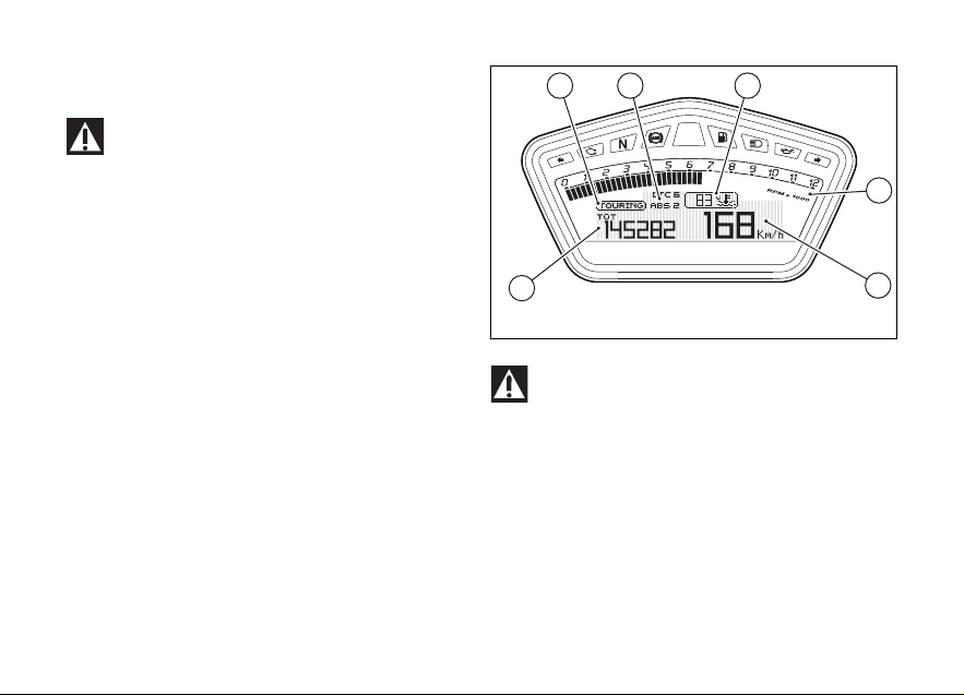
LCD unit functions
2
1
45
3
6
Attention
Adjustments/settings on the instrument panel
are strictly to be carried out when the motorcycle is
stationary. Never operate the instrument panel
controls while riding the motorcycle.
Data displayed on the main screen are as follows:
1) Engine RPM Indicator;
2) Vehicle Speed Indicator;
3) MENU 1 (Odometer, Trip 1, Trip 2, Trip Fuel,
Average Consumption, Instantaneous Consumption,
Average Speed and Trip Time) – UP-MAP Menu and
Riding Mode Set-up Menu;
4) MENU 2 (Engine Coolant Temperature, Ambient
Air Temperature and Clock);
5) Name of set Riding Mode;
6) Riding Mode DTC and ABS settings.
Fig 11
Important
Stop riding if the temperature reaches the
maximum value, otherwise the engine might be
damaged.
36
Page 39

LCD - How to set/display parameters
1
2
Upon key-on, the instrument panel enables the rev
counter, which increases from 0 to 11,000 and
decreases going back to 0; the "DUCATI
HYPERMOTARD" lettering is enabled, in a scrolling
manner, on the Dot-Matrix area; warning lights come
on in sequence from the outside to the inside.
Once check is completed, the instrument panel
always displays Odometer (TOT), engine coolant
temperature and "Riding mode" functions as "main"
indicators.
Fig 12
37
Page 40

Once initial check is completed, the instrument panel
14
83
5 6
2
always goes to the "main" displaying page, with the
following information appearing on the display:
- MENU 1 (3): TOT - Odometer;
- MENU 2 (4): engine coolant temperature
indicator
- SET UP - Set "Riding Mode" indicator (5);
- Engine RPM indicator (RPM) (7);
- Vehicle speed indicator (8);
- "SERVICE" indicator (if active, only).
Press button (2) to scroll MENU 1 and shift to the
following functions:
- TRIP 1 - Trip meter 1;
- TRIP 2 - Trip meter 2;
- TRIP FUEL - Fuel reserve trip meter (if active,
only);
- CONS. AVG - Average Fuel Consumption;
- CONS. - Current fuel consumption;
- SPEED AVG - Average speed;
- TRIP TIME - Trip time.
38
Fig 13
Press button (1) to scroll MENU 2 and shift to the
following functions:
- AIR - Air temperature;
- Clock.
Page 41

Vehicle speed indicator
This function shows vehicle speed (Km/h or mph,
based on the selected unit of measurement).
The instrument panel receives information about the
actual speed (calculated in km/h) and displays the
number increased by 5%.
Maximum speed displayed is 186 mph (299 km/h).
Over 186 mph (299 km/h) a series of dashes will be
displayed “- - -” (not flashing).
Note
If instrument panel is receiving no data, a string
of dashes will be displayed “- - -” (not flashing).
Fig 14
39
Page 42
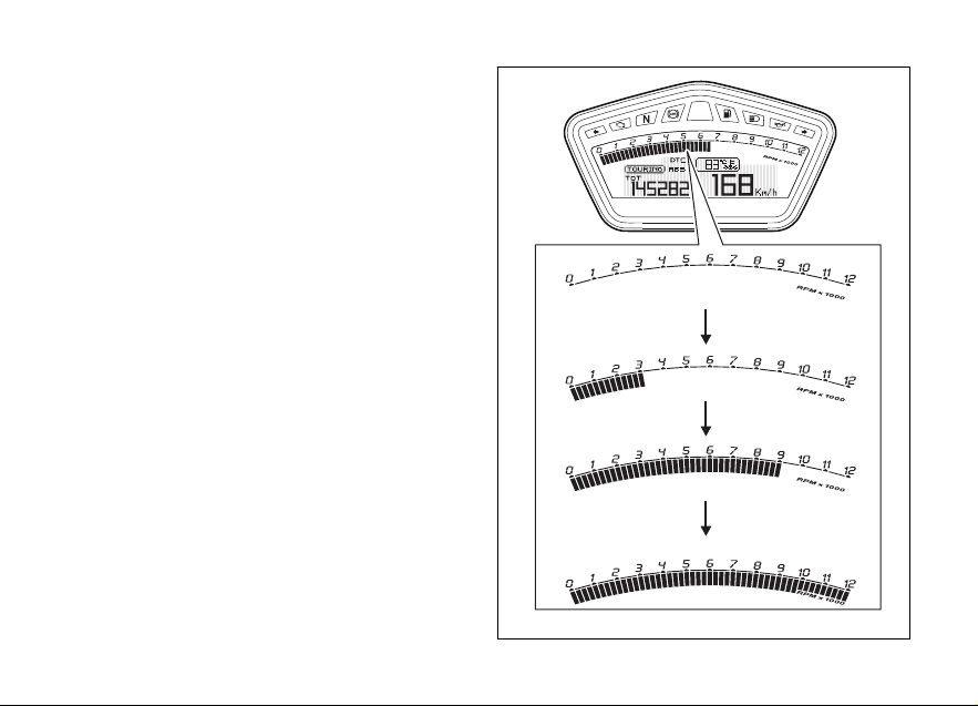
Engine rpm indicator (RPM)
This function shows engine rpm.
The instrument panel receives the engine rpm
information and displays it.
This information on rpm is displayed progressively
from left to right.
40
Fig 15
Page 43
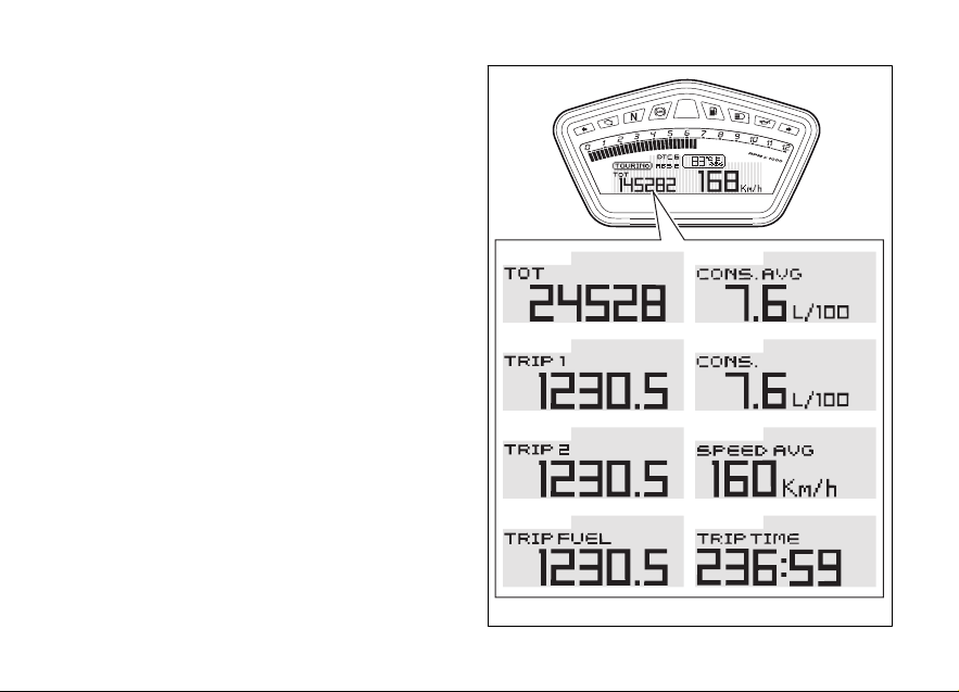
Menu 1 functions
MENU 1 functions are:
- Odometer (TOT);
- Trip meter 1 (TRIP1);
- Trip meter 2 (TRIP2);
- Partial fuel reserve counter (TRIP FUEL);
- Average Fuel Consumption (CONS. AVG);
- Instantaneous fuel consumption (CONS.);
- Average speed (SPEED AVG);
- Trip time (TRIP TIME).
Fig 16
41
Page 44

Menu 1 functions: Odometer (TOT)
This function shows the total distance traveled (km
or miles, based on the specific application).
At Key-On the system automatically enters this
function.
The odometer reading is stored permanently and
cannot be reset.
If the distance traveled exceeds 199999 mi (or
199999 km), the value “199999” will be displayed
permanently.
Note
Value will not be lost upon Battery Off.
Note
If a string of flashing dashes " ----- " is displayed
within odometer function, please contact a Ducati
Dealer or Authorized Service Center.
42
Fig 17
Page 45

Menu 1 functions: Trip meter (TRIP 1)
1
This function shows the partial distance traveled (km
or miles, based on the specific application).
Holding the (1) button pressed for 3 seconds when
this function is displayed resets the trip meter. When
the reading exceeds 9999.9, distance traveled is
reset and the meter automatically starts counting
from 0 again. If the system measurement units are
changed at any moment, or if there is an interruption
in the power supply (Battery Off), the distance
traveled is reset and the count starts from zero
(considering the newly set unit of measurement).
Note
When this value is reset, the “Average fuel
consumption”, “Average speed” and “Trip time”
functions are also reset.
Fig 18
43
Page 46

Menu 1 functions: "Trip 2" meter (TRIP 2)
1
This function shows the partial distance traveled (km
or miles, based on the specific application).
Holding the (1) button pressed for 3 seconds when
this function is displayed resets the trip meter. When
the reading exceeds 9999.9, distance traveled is
reset and the meter automatically starts counting
from 0 again. If the system measurement units are
changed at any moment, or if there is an interruption
in the power supply (Battery Off), the distance
traveled is reset and the count starts from zero
(considering the newly set unit of measurement).
44
Fig 19
Page 47
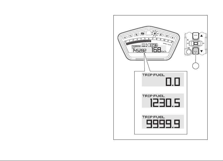
Menu 1 functions: Partial fuel reserve
2
counter (TRIP FUEL)
This function shows the distance traveled (km or
miles, based on the specific application) on fuel
reserve. When the Low fuel light turns on, the display
automatically shows the TRIP FUEL function,
regardless of the currently displayed function; it is
then possible to toggle through the other Menu 1
functions by means of button (2).
Trip fuel reading remains stored even after Key-Off
until the vehicle is refueled. Count is interrupted
automatically as soon as fuel is topped up to above
minimum level. When the reading exceeds 9999.9,
distance traveled is reset and the meter automatically
starts counting from 0 again.
When the TRIP FUEL function is disabled, the
corresponding page inside Menu 1 will not be
available.
Fig 20
45
Page 48

Menu 1 functions: Average Fuel Consumption indicator (CONS. AVG)
This function indicates the “average” fuel
consumption. The calculation is made considering
the quantity of fuel used and the distance traveled
since Trip 1 was last reset. When Trip 1 is reset, the
value is reset and the first value available is displayed
10 seconds after the reset. Dashes “- -.-” are shown
on the display during the first 10 seconds when the
value is not yet available.
The reading is in “mpg” (miles per gallon).
The unit of measurement can be changed through
the "Change unit of measurement (UNITS)" function.
The active calculation phase occurs when the engine
is running and the vehicle is stopped (moments when
the vehicle is not moving and the engine is off are not
considered).
46
Fig 21
Page 49
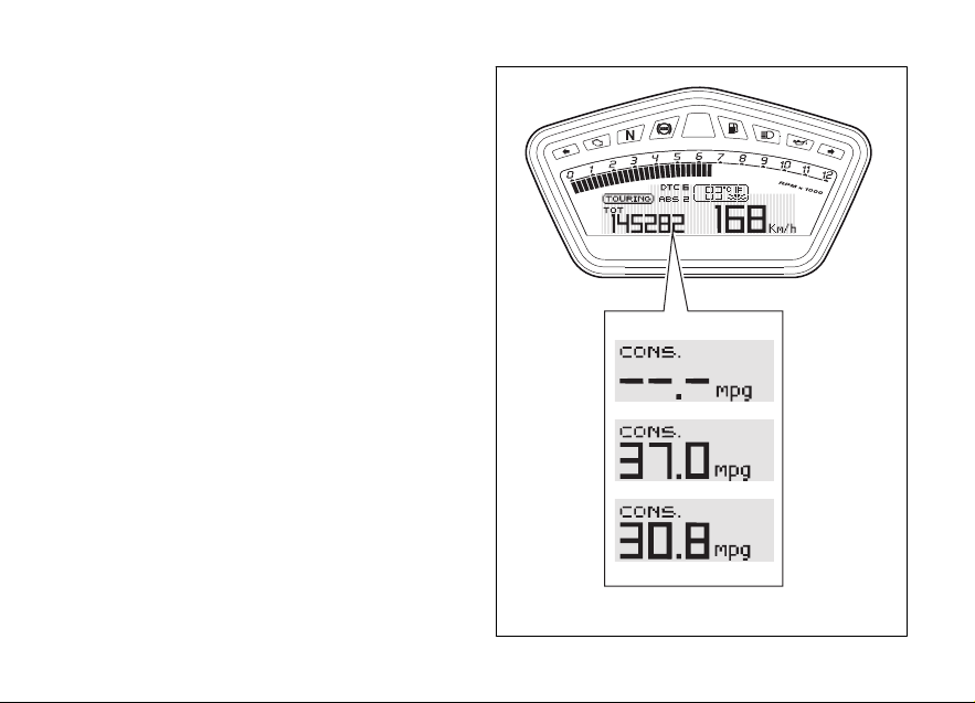
Menu 1 functions: Instantaneous fuel consumption indicator (CONS.)
This function indicates the “instantaneous” fuel
consumption. The calculation is made considering
the quantity of fuel used and the distance traveled
during the last second.
The reading is in “mpg” (miles per gallon).
The unit of measurement can be changed through
the "Change unit of measurement (UNITS)" function.
The active calculation phase only occurs when the
engine is running and the vehicle is moving (times
when the vehicle is not moving when speed is equal
to 0 and/or when the engine is off are not considered).
Dashes “- -.-”. are shown on the display when the
calculation is not being made.
Fig 22
47
Page 50

Menu 1 functions: Average speed indicator (SPEED AVG)
This function shows the average speed of the
motorcycle.
The calculation considers the distance and time since
Trip 1 was last reset. When Trip 1 is reset, the value
is reset and the first value available is displayed 10
seconds after the reset.
Dashes “- -.-” are shown on the display during the
first 10 seconds when the value is not yet available.
The active calculation phase occurs when the engine
is running and the vehicle is stopped (moments when
the vehicle is not moving and the engine is off are not
considered).
The calculated value is displayed increased by 5% to
align it with the indicated speed of the vehicle.
48
Fig 23
Page 51

Menu 1 functions: Trip time indicator (TIME TRIP)
This function shows the vehicle trip time.
The calculation considers the time since Trip 1 was
last reset. When Trip 1 is reset, this value is reset as
well.
The calculation active phase occurs when the engine
is running and the vehicle is stopped (when the
vehicle is not moving and the engine is off the time
is automatically stopped and restarts when the
counting active phase starts again).
Fig 24
49
Page 52

Menu 2 functions
MENU 2 functions are:
- Engine coolant temperature;
- Ambient air temperature (AIR);
- Clock.
50
Fig 25
Page 53

Menu 2 functions: Coolant temperature
This Function is used to display coolant temperature
(°F or °C, based on the specific application).
The instrument panel receives the temperature
reading value and displays it.
The reading is indicated as follows:
- if the reading is between -38°F and +102°F (-
39°C and +39°C) “LO” is shown on the
instrument panel (steady);
- if the reading is between +104°F and +248°F
(+40°C and +120°C), the reading appears on the
instrument panel (steady);
- if the reading is +250°F (+121°C) or higher, "HI"
is shown flashing on the instrument panel.
Fig 26
51
Page 54

Note
In the event of a sensor "error", a string of
flashing dashes ("---") is shown and the "Engine/
Vehicle diagnosis - EOBD" light comes on.
52
Fig 27
Page 55

Menu 2 functions: Air temperature (AIR)
This function indicates ambient temperature.
Instrument panel takes temperature value directly
from sensor and displays it.
Note
When the vehicle is stopped, the engine heat
may influence the displayed temperature.
Fig 28
53
Page 56

Menu 2 functions: Clock
This function displays the time.
Time is always displayed as follows:
- AM from 0:00 to 11:59;
- PM from 12:00 to 11:59.
If battery power is suddenly cut off (Batt-OFF): when
battery power is restored and upon next Key-On, the
clock is reset and restarts operating from "0:00".
54
Fig 29
Page 57

SET UP - Riding Mode set
This function indicates the "Riding Mode” set for the
vehicle.
Each riding mode can be changed using the “Riding
Mode” function.
The set riding mode, the Traction Control level (DTC)
and corresponding ABS level are indicated.
Three different riding modes can be set: SPORT,
TOURING, URBAN.
Fig 30
55
Page 58
SERVICE function - Maintenance interventions
This indicator is used to inform the user to contact an
authorized Ducati Service Center to carry out the
scheduled maintenance operations (service) on the
vehicle.
All maintenance indicators can be "Reset" only by the
authorized Ducati Service Center that will service the
vehicle.
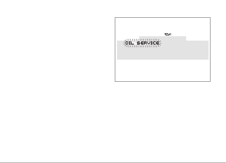
First indicator: OIL SERVICE (600 mi - 1,000
Km)
The first maintenance indicator is the "OIL SERVICE"
signal, coming on when the first 600 miles (1,000 km )
are reached on the odometer. The "OIL SERVICE"
indicator will come on flashing for 5 seconds upon
every Key-ON; while the OIL SERVICE symbol will
remain steady on. Both signals will be active until
"Reset" by the authorized Ducati Service Center.
56
Fig 31
Page 59

Mileage countdown indicator - OIL SERVICE or
DESMO SERVICE (countdown)
After the "OIL SERVICE" indicator has been "reset" for
the first time (after 600 mi - 1,000 km), upon every
Key-On the instrument panel will show the following
service indicator ("OIL SERVICE" or "DESMO
SERVICE") as well as the mileage countdown
indicator.
"OIL SERVICE" or "DESMO SERVICE" indicators, as
well as the relevant symbols and mileage countdown,
will come steady on for 2 seconds upon every KeyOn.
When just 600 mi (1,000 km) are left before service
threshold is reached, the indicator will be enabled
(steady on) upon key-On for 5 seconds (instead of 2
seconds).
Both signals will be active until "Reset" by the
authorized Ducati Service Center.
Fig 32
57
Page 60
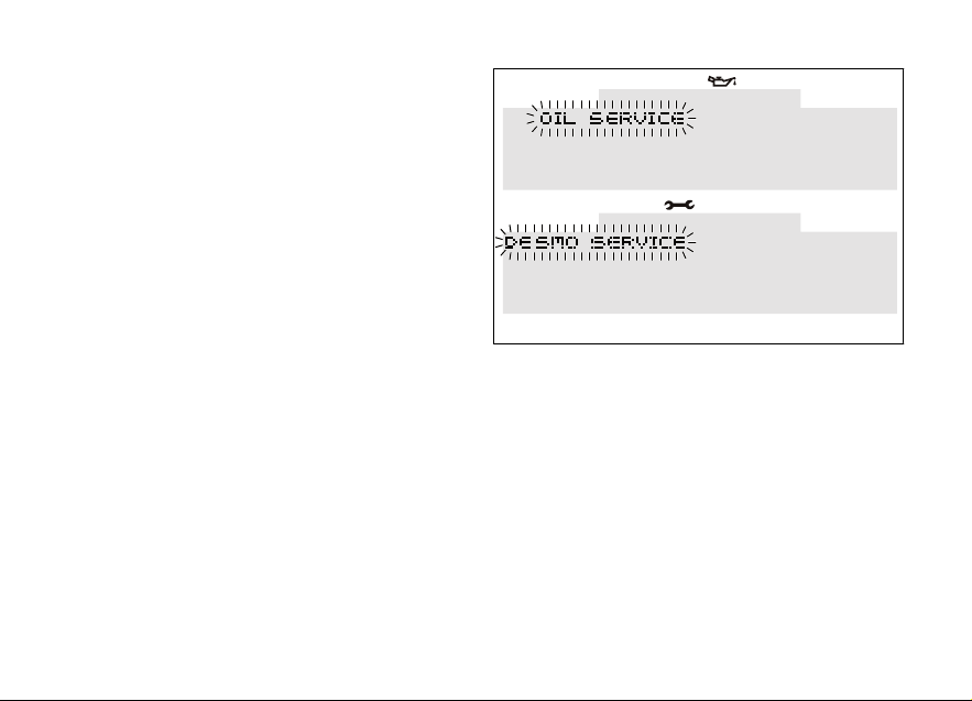
OIL SERVICE or DESMO SERVICE indicator
(mileage reached)
Whenever the threshold required to carry out a
maintenance operation is reached, the type of
operation to be carried out ("OIL SERVICE" or
"DESMO SERVICE") will come on upon each key-On.
The "OIL SERVICE" or "DESMO SERVICE" indicators
will come on (flashing) upon each Key-On for 5
seconds; while the OIL SERVICE or DESMO
SERVICE symbols will be displayed steady on.
Both signals will be active until "Reset" by the
authorized Ducati Service Center.
58
Fig 33
Page 61

Active / not active ERRORS indication
This function indicates that one or more errors are
present.
The type and number of errors can be displayed using
the Setting Menu through the ERRORS function;
when "ERRORS" is off, no errors are present.
Fig 34
59
Page 62
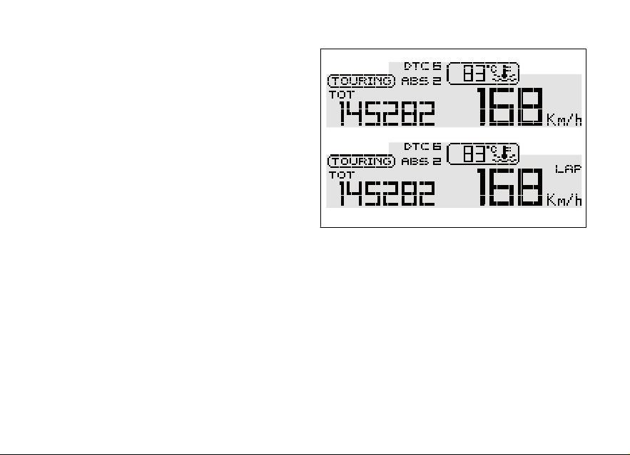
Indication if the LAP function is active/not active
This function indicates if the LAP function (Lap time)
is active.
When "LAP" is off, function is disabled.
60
Fig 35
Page 63
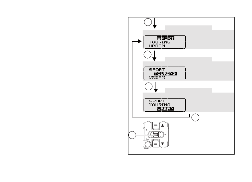
Riding Mode SET UP function (riding style
4
4
4
4
4
change)
This function allows changing vehicle riding mode.
Each riding mode is associated to a different
intervention level of the traction control system (DTC
- Ducati Traction Control), a different braking control
(ABS - Anti-lock Braking System) and a different
engine output and power (Engine). To change bike
riding mode, simply press button (4) once, and the
corresponding menu will be displayed. Whenever
vehicle riding mode is changed, the following
features will also be changed:
- traction control system “DTC” intervention level
(1, 2, 3, 4, 5, 6, 7, 8 and OFF);
- "Engine" power that will consequently change
also throttle behavior (HIGH, MEDIUM and
LOW);
- "ABS" system calibration (1, 2 and OFF).
Whenever button (4) is pressed, instrument panel will
display all riding modes one after the other in a scroll
up-and-down view.
Fig 36
61
Page 64

Once the desired riding mode is highlighted, keep
button (4) pressed for 3 seconds and instrument
panel will check throttle control position and front and
rear brake pressure:
- if throttle control is "closed" and brakes are
released or vehicle is stopped, the instrument
panel will confirm the selected riding mode (*)
and go back to the standard screen view;
- if throttle control is "open" or brakes are pressed
and vehicle is moving, instrument panel will
enable the "CLOSE THROTTLE AND RELEASE
BRAKES" indicator on the display and, only when
all the required conditions are fulfilled (closed
throttle and released brakes or vehicle stopped)
the instrument panel will confirm the selected
riding mode (*) and go back to the standard
screen view.
Note
(*) If the change of Riding mode involves a
change in the ABS status (on-off or off-on), as soon
as the selected riding mode is confirmed, the
instrument panel also starts the "procedure for
enabling/disabling the ABS".
62
Fig 37
If throttle control is not closed and brakes are not
released or vehicle is not stopped within 5 seconds
after the "CLOSE THROTTLE AND RELEASE
BRAKES" warning is displayed, the Riding Mode
change selection procedure will not be executed and
the instrument panel will go back to the standard
screen view without any setup change.
Page 65

If the "SET UP" menu is enabled and button (4) is not
4
pressed for 10 consecutive seconds, the instrument
panel will automatically quit the displayed page
without any setup change.
Attention
Ducati recommends changing the Riding mode
when the vehicle is stopped. If the riding mode is
changed while riding, be very careful (it is
recommended to change the Riding mode at a low
speed).
Fig 38
63
Page 66

Error display (ERRORS)
This function identifies any abnormal vehicle
behavior.
The instrument panel activates any abnormal vehicle
behavior in real time (ERRORS).
If one or more "errors" occur during bike operation,
the "ERROR" indicator will appear on display RH side.
Under these circumstances (one ore more errors
present) the "EOBD" warning light will always come
on.
To display error list, access the Setting Menu and
select the "ERRORS" page; this page will be active
only if at least one error is present.
64
Fig 39
Fig 40
Page 67

If one ore more errors are present, also "NEXT" and
"PREVIEW" will be automatically activated in order to
go from one page to another.
To go from one page to another, select "NEXT" and
"PREVIEW" with buttons (1) and (2), then press button
(4).
The Setting Menu can be quit and accessed at any
time by simply pressing button (4), with the
highlighted "EXIT" indicator.
Attention
When one or more errors are displayed, always
contact a Ducati Dealer or Authorized Service Center.
65
Page 68

1
2
4
1
2
2
1
2
Fig 41
66
Page 69

The table below shows the errors that can be displayed:
Displayed error Description
CAN LINE CAN line "BUS Off" (communication line of the several control units)
UNKNOWN DEVICE Control unit not acknowledged by the system - wrong SW
ABS (Antilock Braking System) ABS control unit faulty communication / operation
BBS (Black Box System) BBS control unit faulty communication / operation
BBS control unit general malfunction
Exhaust valve motor malfunction EXVL
INSTRUMENT PANEL DSB control unit faulty communication / operation
IMMOBILIZER No key
Key not acknowledged
Faulty antenna
ENGINE ECU control unit faulty communication / operation
General malfunction of the ECU control unit
throttle position sensor malfunction
Throttle motor and/or relay malfunction
pressure sensor malfunction
engine coolant temperature sensor malfunction
67
Page 70

Displayed error Description
intake duct air temperature sensor malfunction
injection relay malfunction
ignition coil malfunction
injector malfunction
engine rpm sensor malfunction
lambda sensor or lambda sensor heater malfunction
vehicle starting relay malfunction
secondary air sensor malfunction
FUEL SENSOR reserve NTC sensor malfunction
SPEED SENSOR front and/or rear speed sensor malfunction
BATTERY battery voltage too high or too low
STOP LIGHT stop light not working
FAN electric cooling fan malfunction
T_AIR SENSOR Ambient air temperature sensor malfunction
H.GRIPS Malfunction of one or more heated handgrips
68
Page 71

SETTING MENU
This menu is used to set/enable some motorcycle
functions.
To access the Setting Menu, keep button (2) pressed
for two seconds; once this menu is accessed it will
no longer be possible to scroll functions on the
Display.
Important
For safety reasons, the setting menu can only
be accessed when motorcycle speed is lower than or
equal to 12.43 mph (20 km/h). If this menu is open
and the speed of the motorcycle exceeds 12.43 mph
(20 km/h) the instrument panel automatically exits the
menu and returns to the "main" display.
The setting menu contains the following items:
- riding mode customization (R.MODE);
- backlighting adjustment (B.LIGHT);
- lap time activation and displaying (LAP);
- PIN CODE activation and editing (PIN);
- clock setup (CLOCK);
- measurement unit setup (UNITS);
- battery voltage indicator (BATT.)
- engine RPM indicator (RPM);
- error indicator, only if one or more errors are
present (ERRORS);
- EXIT.
To quit the setting menu, use buttons (1) and (2) to
highlight the "EXIT" wording, then press button (4).
69
Page 72

1
2
4
1
2
4
70
Fig 42
Page 73

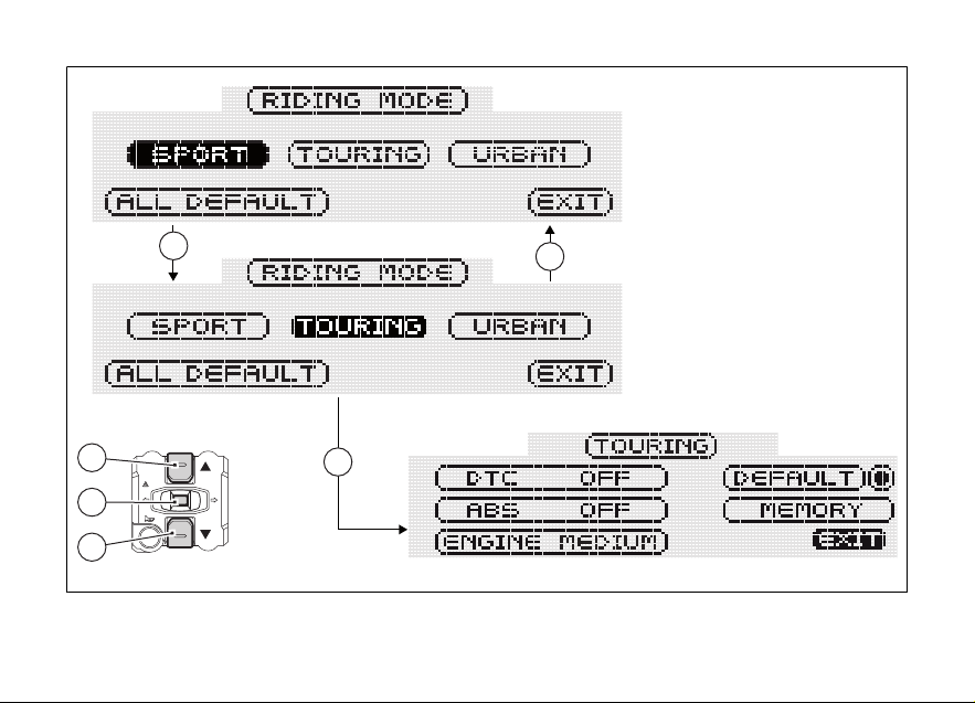
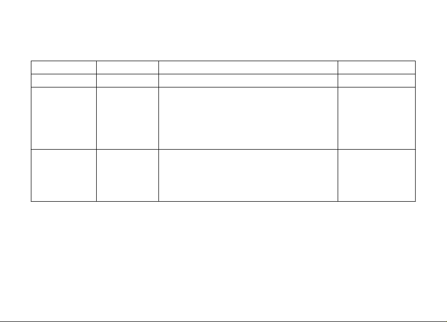
Customizing Riding Modes (R.MODE)
This function customizes each riding style.
To display this function, access the Setting Menu and
select the R.MODE page.
When accessing this function, the three riding modes
- SPORT, TOURING and URBAN - will be displayed.
The ALL DEFAULT function will also be displayed;
this function is used to reset Ducati default setup
parameters for all riding modes.
Buttons (1) and (2) can also be used to select the
riding mode you wish to edit or the ALL DEFAULT
function.
Note
If on ALL DEFAULT lettering right side a symbol
is displayed, this means that the default setup is
active, namely that the parameters shown are those
set up by Ducati.
71
Page 74
1
2
4
1
2
4
Fig 43
72
Page 75

To customize parameters, select the riding mode you
wish to edit and press button (4).
Customizable parameters are DTC (Ducati Traction
Control), ABS (Antilock Braking System) and ENGINE
(engine power).
Use buttons (1) and (2) to select the parameter you
wish to customize.
All edited (customized) parameters are stored inside
memory even after a Battery-Off.
The parameters of a single riding mode can also be
reset through the DEFAULT function.
Note
If on DEFAULT lettering right side a symbol is
displayed, this means that the default setup is active,
namely that the parameters shown are those set up
by Ducati.
Attention
Changes should only be made to the
parameters by people who are experts in motorcycle
setup; If the parameters are changed accidentally,
use the "DEFAULT" function to reset the parameters.
73
Page 76

1
2
4
4
2
1
1
Fig 44
74
Page 77
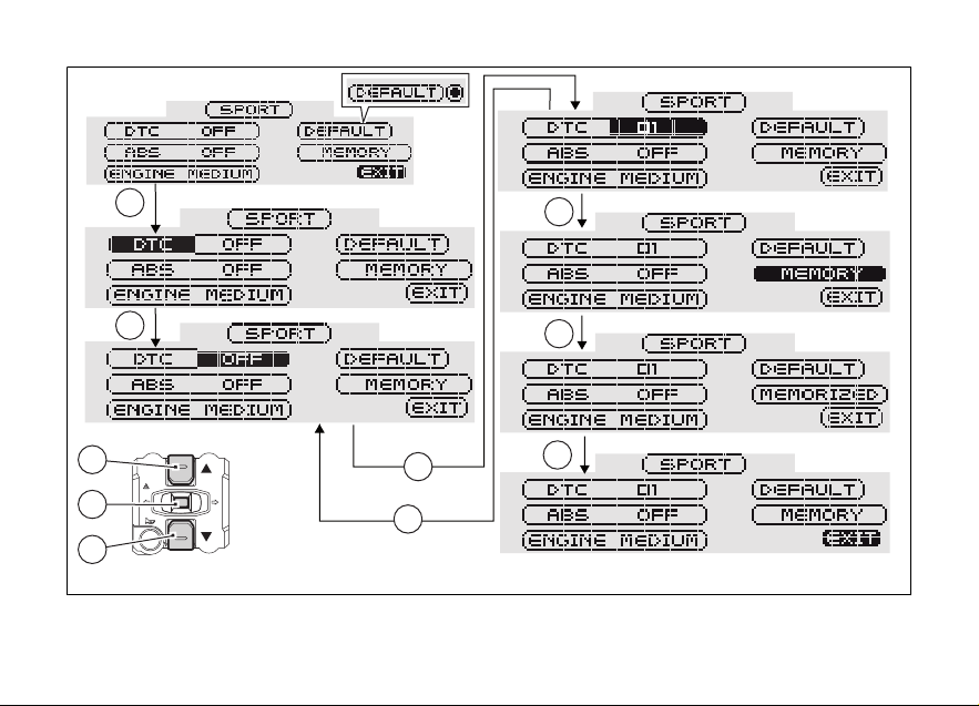
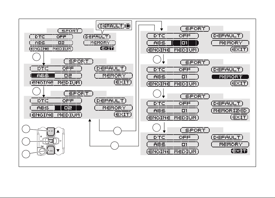
DTC set up
This function allows customizing DTC (Ducati
Traction Control) intervention level and, if necessary,
disabling it.
To display this function, access the Setting Menu and
select the R.MODE page.
Use buttons (1) and (2) to select the riding mode you
wish to edit, then press button (4).
Use keys (1) and (2) to select the DTC indicator, then
press button (4) to access the setup page.
Now, always using buttons (1) and (2), you can
increase or decrease DTC level; press button (4) to
confirm the new level.
The different settings are 01 to 08 and OFF.
Note
If OFF is set, the DTC will be disabled.
Once the new setup is selected, press button (4).
The instrument panel will automatically highlight the
"MEMORY" indicator; to store the new setup, keep
button (4) pressed for 3 seconds. After this time, the
instrument panel will display the "MEMORIZED"
indicator for 2 seconds as a confirmation of the
change made.
The "EXIT" indicator will be automatically highlighted;
press button (4) to quit this page and go back to the
setting menu.
Note
If on DEFAULT lettering right side a symbol is
displayed, this means that the default setup is active,
namely that the parameters shown are those set up
by Ducati.
75
Page 78
1
2
4
1
4
4
4
1
1
2
76
Fig 45
Page 79

The following table indicates the most suitable level of DTC intervention for the various riding types as well
as the default settings in the "Riding Modes" that can be selected by the rider:
DTC LEVEL RIDING MODE USE DEFAULT?
1 TRACK Professional Track use for very experi-
enced riders. System permits sliding sideways.
2 TRACK Track use (and road use
for expert riders).
3 SPORT Sporty driving on a road or
track.
4 TOURING Touring extra-urban use. It is the default level for
5 CRUISE Cruise touring use. NO
6 URBAN Urban use. It is the default level for
7 RAIN Wet or moist road. NO
8 HEAVY RAIN Wet road with heavy rain
or very slippery asphalt.
NO
NO
It is the default level for
the “SPORT” Riding
Mode
the “TOURING” Riding
Mode
the “URBAN” Riding
Mode
NO
77
Page 80

Tips on how to select the sensitivity level
Attention
The 8 level settings of the DTC were calibrated
using tires of the same make, model and size as
those originally fitted on the motorcycle. Using tires
of a different size from the original tires may alter the
operating characteristics of the system.
Motorbike original equipment: (front 120/70ZR17 rear 180/55ZR17).
- Pirelli Diablo Supercorsa SP;
- Pirelli Diablo Rosso II;
- Pirelli Scorpion Trail.
In the case of minor differences, such as for example,
tires of a different make and/or model than the OE
ones, but with the same size (rear = 180/55-17; front
= 120/70-17), it may be sufficient to simply select the
most suitable level setting from those available to
restore optimal system operation. If tires of a
different size class are used or if the tire dimensions
differ significantly from the original tires, it may be
that the system operation is affected to the point
where none of the 8 available level settings will give
78
satisfactory results. In this case it is advisable to
deactivate the traction control system. If level 8 is
selected, the DTC control unit will kick in at the
slightest hint that the rear wheel is starting to spin.
Between level 8 and level 1 there are an additional 8
intermediate levels. The level of DTC intervention
decreases in equal steps from level 8 to level 1. When
level 1 or 2 is selected the DTC control unit will allow
the rear wheel to spin and also slide sideways on
exiting a corner; we recommend that this setting is
only used by very experienced riders on the track.
The choice of the correct level depends on 3 main
variables:
1) The grip (type of tire, amount of tire wear, the
road/track surface, weather conditions, etc.);
2) The characteristics of the path/circuit (bends all
taken at similar speeds or at very different
speeds);
3) The riding mode (whether the rider has a
“smooth” or a “rough” style).
The relation of the DTC intervention level to grip
conditions:
Page 81

The choice of level setting depends greatly on the
grip conditions of the track/circuit (see below, tips for
use on the track and on the road).
The relation of the DTC intervention level to the circuit
characteristics:
If all the corners on the track/circuit can be taken at a
similar speed, it will be easier to find an intervention
level that is satisfactory for every bend; on the other
hand, if the track has, for example, one corner that is
much slower than all the others, it will be necessary
to find a compromise level (on the slow corner the
DTC will tend to control more than on the faster
corners).
The relation of the DTC intervention level to riding
style:
The DTC will tend to kick in more with a “smooth”
riding mode, where the bike is leaned over further,
rather than with a “rough” style, where the bike is
straightened up as quickly as possible when exiting a
turn.
Tips for use on the track
We recommend that level 6 be used for a couple of
full laps (to allow the tires to warm up) in order to get
used to the system. Then try levels 5, 4, etc., in
succession until you identify the DTC sensitivity level
that suits you best (always try each level for at least
two laps to allow the tires to warm up).
Once you have found a satisfactory setting for all the
corners except one or two slow ones, where the
system tends to kick in and control too much, you can
try to modify your riding style slightly to a “rougher”
approach to cornering i.e. straighten up more rapidly
on exiting the corner, instead of immediately trying a
different level setting.
Tips for use on the road
Activate the DTC, select DTC 6 and ride the
motorcycle in your usual style; if the DTC intervention
level seems excessive, try DTC 5; if also this RM is
too strong, try DTC 4. If none of the available level
settings meets your riding style, you can select the
level by following the indications given in the table
above until you find the level that suits you best.
If changes occur in the grip conditions and/or circuit
characteristics and/or your riding style, and the level
setting is no longer suitable, switch to the next level
up or down and proceed to determine the best
setting (e.g. if with level 7 the DTC intervention
seems excessive, switch to level 6; alternatively, if on
79
Page 82

level 7 you cannot perceive any DTC intervention,
switch to level 8).
80
Page 83

ABS set up
This Function allows customization of the ABS
(Antilock Braking System) level as well as its
disabling. To display this function, access the Setting
Menu and select the R.MODE page.
Use buttons (1) and (2) to select the riding mode you
wish to edit, then press button (4). Use keys (1) and
(2) to select the ABS indicator, then press button (4)
to access the setup page. Now, always using buttons
(1) and (2), you can increase or decrease ABS level;
press button (4) to confirm the new level.
The different settings are 01, 02 and OFF.
Note
If OFF is set, the ABS will be disabled and the
corresponding ABS warning light will start flashing.
Once the new setup is selected, press button (4). The
instrument panel will automatically highlight the
"MEMORY" indicator; to store the new setup, keep
button (4) pressed for 3 seconds.
After this time, the instrument panel will display the
"MEMORIZED" indicator for 2 seconds as a
confirmation of the change made. The "EXIT" indicator
will be automatically highlighted; press button (4) to
quit this page and go back to the setting menu.
Note
If ABS OFF is selected and stored, Ducati
recommends paying the utmost attention while
riding and braking your bike.
Note
If on DEFAULT lettering right side a symbol is
displayed, this means that the default setup is active,
namely that the parameters shown are those set up
by Ducati.
81
Page 84
1
2
4
1
4
4
4
1
1
2
82
Fig 46
Page 85
The following table indicates the most suitable level of ABS intervention for the various riding types, as well
as the default settings in the "Riding Mode" that can be selected by the rider:
LEVEL STYLE USE DEFAULT?
OFF The ABS is disabled. NO
1 SPORT For road use in good grip conditions. Under this
mode, ABS is active on both wheels. Lift-up prevention controls are active; this calibration favors
braking power and ensures, at the same time,
good stability levels during braking and lift-up control*.
2 URBAN For use under any riding condition. Under this
mode, ABS is active on both wheels. This calibration favors vehicle max. stability and lift-up prevention and ensures, at the same time, a top level
max. deceleration performance.
It is the default level
for the "SPORT" and
“TOURING” Riding
Modes.
It is the default level
for the “URBAN”
Riding Mode.
83
Page 86

Tip on how to select the sensitivity level
Attention
The ABS system levels of your vehicle were
calibrated using the same tires as those originally
supplied with your motorcycle.
If tires of a different size class are used or if the tire
characteristics differ significantly from the original
ones, system operation could be affected so much
and no longer be safe. We do not recommend using
tires having a different size class from those approved
for your vehicle.
Motorbike original equipment: (front 120/70ZR17 rear 180/55ZR17).
- Pirelli Diablo Supercorsa SP;
- Pirelli Diablo Rosso II;
- Pirelli Scorpion Trail.
If level 2 is selected, the ABS system will be activated
to ensure a very stable braking and a good bike
control as well as to prevent any lift-up, thus allowing
a good vehicle alignment during the whole braking
action. When shifting from level 2 to level 1, braking
power will be favored compared to max. stability
84
control and lift-up prevention, which is nevertheless
still active.
The choice of the correct level mainly depends on the
following parameters:
1) Tire/road grip conditions (type of tire, amount of
tire wear, road/track surface, weather conditions,
etc.).
2) Rider experience and skill.
Under poor grip conditions (see point 1) and/or for
less experienced riders, we recommend using level
2.
Page 87

ENGINE set up
This function customizes ENGINE power and output.
To display this function, access the Setting Menu and
select the "R.MODE" page. Use buttons (1) and (2) to
select the riding mode you wish to edit, then press
button (4).
Use keys (1) and (2) to select the "ENGINE" indicator,
then press button (4) to access the setup page..
Now, always using buttons (1) and (2), you can
increase or decrease ENGINE level; press button (4)
to confirm the new level.
The different settings are HIGH, MEDIUM and LOW.
Once the new setup is selected, press button (4). The
instrument panel will automatically highlight the
"MEMORY" indicator; to store the new setup, keep
button (4) pressed for 3 seconds.
After this time, the instrument panel will display the
"MEMORIZED" indicator for 2 seconds as a
confirmation of the change made. The "EXIT" indicator
will be automatically highlighted; press button (4) to
quit this page and go back to the setting menu.
Note
If on DEFAULT lettering right side a symbol is
displayed, this means that the default setup is active,
namely that the parameters shown are those set up
by Ducati.
85
Page 88

1
2
4
1
4
4
4
1
1
2
86
Fig 47
Page 89

ALL DEFAULT (Resetting the default parameters of all Riding Modes)
This function allows restoring all Ducati setup
parameters for SPORT, TOURING and URBAN Riding
Modes.
To display this function, access the Setting Menu and
select the "R.MODE" page.
Use buttons (1) and (2) to select the "ALL DEFAULT"
indicator, then keep button (4) pressed for 3 seconds.
Now the "ALL DEFAULT" wording will be replaced by
the "PLEASE WAIT..." indicator, which will be
displayed for 3 seconds to inform the user that the
instrument panel is restoring the default parameters
for all Riding Modes.
After this time (3 seconds), the "EXIT" indicator will be
automatically highlighted; press button (4) to quit this
page and go back to the setting menu.
Note
If on ALL DEFAULT lettering right side a symbol
is displayed, this means that the default setup is
active, namely that the parameters shown are those
set up by Ducati.
87
Page 90
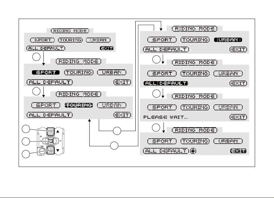
1
2
4
1
1
4
4
1
1
2
88
Fig 48
Page 91

DEFAULT (Resetting the default parameters of a single Riding Mode)
This function allows restoring all Ducati setup
parameters for a single Riding Mode.
To display this function, access the Setting Menu and
select the "R.MODE" page.
Use buttons (1) and (2) to select the riding mode for
which you wish to restore the default parameters,
then press button (4). Use buttons (1) and (2) to select
the "DEFAULT" indicator, then keep button (4)
pressed for 3 seconds.
Now the "DEFAULT" wording will be replaced by the
"PLEASE WAIT..." indicator, which will be displayed
for 3 seconds to inform the user that the instrument
panel is restoring the default parameters for the
selected Riding Mode.
After this time (3 seconds), the "EXIT" indicator will be
automatically highlighted; press button (4) to quit this
page and go back to the setting menu.
Note
When the default settings are active, a symbol
(circle with a dot) is always displayed close to the
DEFAULT indicator (on the right).
89
Page 92

1
2
4
1
1
1
4
1
Fig 49
90
Page 93

Dashboard backlighting setting function (B.LIGHT)
This function adjusts the instrument panel
backlighting intensity.
To display the function, enter the “setting” menu and
access the “B.LIGHT” page.
The information will be displayed as follows:
- the tick (V) indicates that the setting is currently
enabled;
- use buttons (1) and (2) to highlight the new
setting;
- to store the new setting, press button (4); the tick
(V) will move on the stored condition.
To quit this page, highlight the "EXIT" wording, and
press button (4).
1) HIGH setting: when this condition is stored,
backlighting is at the max. level.
2) MEDIUM setting: when this condition is stored,
backlighting is reduced by approx. 30%
compared to max. level.
3) LOW setting: when this condition is stored,
backlighting is reduced by approx. 70%
compared to max. level.
Note
In the event of an interruption of the power
supply from the battery, when power is restored at
the next Key-On, the backlighting will always be set
by default to maximum brightness.
91
Page 94

1
2
4
1
1
4
1
1
Fig 50
92
Page 95

Lap time function (LAP): LAP activation/ deactivation function
This function activates and deactivates the LAP
function (lap time).
To display the function, enter the “setting” menu and
access the “LAP” page.
The information will be displayed as follows:
- the tick (V) indicates that the setting is currently
enabled;
- use buttons (1) and (2) to highlight the new
setting;
- to store the new setting, press button (4); the tick
(V) will move on the stored condition.
To quit this page, select the "EXIT" wording, and press
button (4). Storing the “OFF” condition disables the
LAP function.
Storing the "ON" condition enables the LAP function.
Note
When the LAP function is enabled, button (3)
can be used both as high beam Flash and lap time
Start/Stop.
93
Page 96
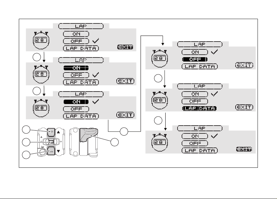
1
2
4 3
1
4
1
1
1
94
Fig 51
Page 97

Lap time function (LAP): LAP registration
This function is used to describe how lap times (LAP)
are stored.
If function is enabled, lap time can be stored as
follows:
- after the first time you press button (3) the first
lap counter is started and the instrument panel
displays the "START LAP" indicator (flashing) for
4 seconds, before reverting to previous display;
- from now on, each time you press button (3), the
instrument panel will show the lap time for 10
seconds (steady), before reverting to the
previous display.
You can save a maximum of 30 laps in the memory.
If the memory is full, each time you press button (3),
the instrument panel will not be able to save any lap
time and, for 4 seconds, the display will show the
message “LAP MEM. FULL" (flashing) until the
memory is reset.
When the LAP function is set to Off, the current "lap"
is not stored. If the LAP function is active and the
motorcycle is suddenly turned off (Key-Off), the
function will be automatically disabled (even if the lap
timer was active, the current "lap" is not stored).
If the timer is not stopped, when it reaches 9
minutes, 59 seconds and 99 hundredths, it restarts
from 0 (zero) and continues until the function is
switched off.
If the LAP function is enabled without resetting the
memory and there are less than 30 laps stored in the
memory (for instance: 18 laps), the instrument panel
will store any remaining laps until the memory is full
(in this case, it will store an additional 12 laps).
This function only displays lap times being stored;
however, other data (MAX Speed, RPM MAX, rev
limiter - if tripped) are saved for a subsequent
complete display in the LAP displaying function.
95
Page 98

3
3
Fig 52
96
Page 99

Funzione Tempo sul giro (LAP): stored LAP
4
1
2
4
display
This function displays the stored LAPs. To display the
function, enter the “setting” menu and access the
“LAP” page. Use buttons (1) and (2) to highlight the
"LAP DATA" indicator, then press button (4).
The instrument panel will display the information as
follows:
- lap number being displayed (example: No.1);
- NEXT indicator to view next LAP;
- ERASE indicator to delete all stored lap times;
- TIME: and then lap time (example: 1’50’’97);
- RPM MAX: max. engine RPM reached during the
stored LAP;
- SPEED MAX: max. speed reached during the
stored LAP.
To quit this page, select the "EXIT" wording, and press
button (4).
Fig 53
97
Page 100

Note
The MAX stored speed is reached during lap
(increased by 5%).
Note
If MAX speed reading exceeds 186 mph (299
Km/h) while the information is stored, actual speed
reading is displayed (example: 316 Km/h).
Note
If no lap times are saved in memory, the 30 lap
times will be displayed as 0’00’’00, the RPM max.
number equal to 0 (zero) and the MAX speed value
equal to 0 (zero).
Note
If the engine trips the threshold before the rev
limiter kicks in or makes the rev limiter kick in during
lap saving, the corresponding Over Rev light will
come on during the displaying of the stored lap times.
98
Fig 54
 Loading...