

Page 1

Manuale d’officina
Workshop manual
Model Year 2004
DUCATI
999RS04
914.7.056.1A 914.7.056.1A
cod.
914.7.056.1A
914.7.056.1A 914.7.056.1A
Page 2

999RS04
PREMESSA
- Gli interventi descritti nel presente
manuale, richiedono esperienza e
competenza da parte dei tecnici
preposti, che sono invitati al pieno
rispetto delle caratteristiche
tecniche originali, riportate dal
Costruttore.
- Alcune informazioni sono state
appositamente omesse, poichè, a
nostro avviso, facenti parte
dell'indispensabile cultura tecnica
di base che un tecnico
specializzato deve possedere.
- Altre eventuali informazioni
possono essere dedotte dal
catalogo ricambi.
- Tutto il materiale da utilizzare
dovrà essere ordinato alla Ducati
Corse S.r.l.
- La Ducati Corse S.r.l. declina ogni
responsabilità per errori ed
omissioni di carattere tecnico,
prodotti nella redazione del
presente manuale e si riserva il
diritto di apportare qualsiasi
modifica richiesta dall'evoluzione
tecnologica dei suoi motocicli,
senza l'obbligo di divulgazione
tempestiva.
- Tutte le informazioni riportate,
sono aggiornate alla data di
stampa.
- Riproduzioni o divulgazioni anche
parziali degli argomenti trattati
nella presente pubblicazione,
sono assolutamente vietate. Ogni
diritto è riservato alla Ducati
Corse S.r.l., alla quale si dovrà
richiedere autorizzazione (scritta)
specificandone la motivazione.
FOREWORD
- All operations described in this
manual must be carried out by
senior skilled technicians, who
are requested to strictly follow the
Manufacturer’s instructions.
- Some information has been
intentionally omitted as, at our
advice, a specialized technician
must have this technical
background.
- Other information can be taken
from the spare parts catalogue.
- The orders for all the parts to be
used shall be placed at Ducati
Corse S.r.l.
- Ducati Corse S.r.l. declines all
responsibility for any technical
errors or omissions in this manual
and reserves the right to make
changes without prior notice.
- The information given in this
manual was correct at the time of
going to print.
- Reproduction and disclosure,
even partially, of the contents of
this manual are strictly forbidden
without prior written authorization
of Ducati Corse S.r.l., which has
exclusive right on this manual.
Applications for authorization
must specify the reasons for
reproduction or disclosure.
Ducati Corse S.r.l.
Ducati Corse S.r.l.
999RS - M.Y. 2004 - edizione/edition 01
Page 3

999RS04
Ricomposizione motore
Identificazione sezioni
Engine reassembly
Section identification
INTERVENTI RACCOMANDATI
A
GENERALITÀ
DESCRIPTION
B
MAINTENANCE SCHEDULE
SCOMPOSIZIONE MOTORE
ENGINE DISASSEMBLY
REVISIONE MOTORE
ENGINE OVERHAUL
RICOMPOSIZIONE MOTORE
ENGINE REASSEMBLY
C
C
D
D
E
999RS - M.Y. 2004 - edizione/edition 01
F
MOTOTELAIO
FRAME
G
ELETTRONICA E GESTIONE MOTORE
ENGINE MANAGING AND ELECTRONIC SYSTEMS
Page 4

Page 5

Generalità
Description
A
B
C
D
E
F
G
Page 6

sezione / section
A
999RS04
Generalità
Description
INDICE DI SEZIONE
SIMBOLOGIA DI REDAZIONE
CONSIGLI UTILI
A
NORME GENERALI SUGLI INTERVENTI
RIPARATIVI
CARATTERISTICHE TECNICHE
Motore 10
Distribuzione 10
Alimentazione 11
Accensione 11
Candele 11
B
Lubrificazione 11
Raffreddamento 11
Trasmissione 11
Freni 12
Telaio 12
Sospensioni 13
Ruote 13
Pneumatici 13
Impianto elettrico 13
Pesi 13
C
Ingombri 14
Serbatoio carburante 14
SECTION INDEX
7
GRAPHIC SYMBOLS
8
A WORD OF ADVICE
GENERAL ADVICE ON REPAIR WORK
9
TECHNICAL SPECIFICATIONS
10
Engine 15
Timing system 15
Fuel system 16
Ignition 16
Spark Plugs 16
Lubrication 16
Cooling System 16
Transmission 16
Brakes 17
Frame 17
Suspension 18
Wheels 18
Tyres 18
Electrical system 18
Weights 18
Overall dimensions 19
Fuel tank 19
7
8
9
15
D
E
F
G
6
999RS - M.Y. 2004 - edizione/edition 01
Page 7
sezione / section
A
999RS04
Ricomposizione motore
Generalità
Engine reassembly
Description
SIMBOLOGIA DI REDAZIONE
Per una lettura rapida e razionale
sono stati impiegati simboli che
evidenziano situazioni di massima
attenzione, consigli pratici o semplici
informazioni.
Note
Prestare attenzione al
significato dei simboli in quanto la
loro funzione è quella di non dovere
ripetere concetti tecnici o avvertenze
di sicurezza. E’ fatta prescrizione,
pertanto, seguirne il significato.
Consultare questa pagina ogni volta
che sorgeranno dubbi sul loro
significato.
❍ Questo simbolo, posto all’inizio
del testo, identifica una operazione o
un intervento che costituisce parte
integrante di una procedura di
smontaggio.
● Questo simbolo, posto all’inizio
del testo, identifica un dato o un
riferimento particolarmente
importante per l'operazione in
corso.
▲ Questo simbolo, posto all’inizio
del testo, identifica un’operazione di
rimontaggio.
Tutte le indicazioni alla parte destra
o sinistra del motoveicolo si
riferiscono al senso di marcia dello
stesso.
Attenzione
La non osservanza delle
istruzioni riportate può creare una
situazione di pericolo, causare gravi
lesioni personali e anche la morte.
Importante
Indica la possibilità di
arrecare danno al veicolo e/o
ai suoi componenti se le
istruzioni riportate non vengono
eseguite.
Note
Fornisce utili informazioni
sull'operazione in corso.
GRAPHIC SYMBOLS
For easy and rational reading, this
manual uses graphic symbols for
highlighting situations in which
maximum care is required, practical
advice or simple information.
Note
Please pay maximum
attention to these symbols as they
are meant for not repeating
technical concepts or safety rules.
These symbols must be considered
as “hints” to important information.
Please refer to this page whenever in
doubt as to their meaning.
❍ This symbol, at the start of an
item of text, indicates an operation
which is part of a disassembly
procedure.
● This symbol, at the start of an
item of text, indicates a piece of
information or a reference item
which is particularly important for
the current operation.
▲ This symbol, at the start of an
item of text, indicates a reassembly
operation.
Left-hand and right-hand refer to
the left and right of the vehicle as
seen in the direction of travel.
Warning
Failure to follow the
instructions given in text marked
with this symbol can lead to serious
personal injury or death.
Caution
Failure to follow the
instructions in text marked with this
symbol can lead to serious damage
to the motorcycle and/or its
components.
Note
This symbol indicates
additional useful information for the
current operation.
A
B
C
D
E
F
999RS - M.Y. 2004 - edizione/edition 01
G
7
Page 8

sezione / section
A
999RS04
Generalità
Description
A
B
C
CONSIGLI UTILI
La Ducati consiglia, onde prevenire
inconvenienti e per il raggiungimento
di un ottimo risultato finale, di
attenersi genericamente alle
seguenti norme:
- in caso di una probabile
riparazione valutare le impressioni
del Cliente, evidenzianti
anomalie di funzionamento del
motociclo, e formulare le
opportune domande di chiarimento
sui sintomi dell’inconveniente;
- diagnosticare in modo chiaro le
cause dell’anomalia. Dal presente
manuale si potranno assimilare le
basi teoriche fondamentali, che
peraltro dovranno essere integrate
dall’esperienza personale;
- pianificare razionalmente la
riparazione onde evitare tempi
morti come ad esempio il prelievo
di parti di ricambio, la preparazione
degli attrezzi, ecc.;
- raggiungere il particolare da riparare limitandosi alle operazioni
essenziali.
A tale proposito sarà di valido aiuto la
consultazione della sequenza di
smontaggio esposta nel presente
manuale.
A WORD OF ADVICE
Ducati would like to offer a word or
two of advice on how to best ensure
an efficient, fault-free customer
service.
- When diagnosing breakdowns,
primary consideration should
always be given to what the
customer reports. Your questions
to the customer should aim to
clarify the problem and lead to an
accurate diagnosis of the source of
the trouble.
- Diagnose the problem accurately
before proceeding further. This
manual provides the theoretical
background for troubleshooting to
be integrated with your own
personal experience.
- Repair work should be planned
carefully in advance to prevent any
unnecessary down-time, such as
for example picking-up of required
spare parts or arrangement of
required tools, etc.
- Limit the number of operations
needed to reach the part to be
repaired to the minimum.
The disassembly procedures in this
manual describe the most efficient
way to reach a part to be repaired.
D
E
F
G
8
999RS - M.Y. 2004 - edizione/edition 01
Page 9

sezione / section
A
999RS04
Ricomposizione motore
Generalità
Engine reassembly
Description
NORME GENERALI SUGLI
INTERVENTI RIPARATIVI
- Utilizzare sempre attrezzature di
ottima qualità.
- Per il sollevamento del
motoveicolo, attrezzatura
espressamente realizzata e
conforme alle Direttive Europee.
- Durante le operazioni sul veicolo
montare gli attrezzi a portata di
mano, possibilmente secondo una
sequenza predeterminata, e
comunque mai sul veicolo o in
posizioni nascoste o poco
accessibili.
- Mantenere ordinata e pulita la
postazione di lavoro.
- Sostituire sempre le guarnizioni, gli
anelli di tenuta e le copiglie con
particolari nuovi.
- Allentando o serrando dadi o viti,
iniziare sempre da quelle con
dimensioni maggiori oppure dal
centro; bloccare alla coppia di
serraggio prescritta (Sez. B)
seguendo un percorso incrociato.
- Contrassegnare sempre particolari
o posizioni che potrebbero essere
scambiati fra di loro all’atto del
rimontaggio.
- Utilizzare parti di ricambio originali
Ducati ed i lubrificanti delle marche
raccomandate.
- Usare attrezzi speciali Ducati dove
specificato.
- Consultare le Circolari Tecniche in
quanto potrebbero riportare dati di
regolazione e metodologie di
intervento maggiormente
aggiornate rispetto al presente
manuale.
GENERAL ADVICE ON REPAIR
WORK
- Always use top quality tools.
- Lift the motorcycle with devices in
full compliance with relevant
European directives only.
- During repair work always keep
the tools within reach, possibly in
the right order. Never put them on
the vehicle or in hardly reachable
places or somehow hidden.
- Work place must be neat and
clean.
- During repair work always change
gaskets, seals and split pins.
- When loosening or tightening nuts
and bolts, always start with the
largest or start from the center.
Working crossways, tighten nuts
and bolts to the specified torque
(Sect. B).
- At disassembly, mark any parts
and positions which might easily
be confused at reassembly.
- Use Ducati original spare parts
only. Use the recommended
lubricants only.
- Use Ducati special service tools
where specified.
- Ducati Technical Bulletins often
contain up-dated versions of the
service procedures described in
this manual. Check the latest
Bulletins for details.
A
B
C
D
999RS - M.Y. 2004 - edizione/edition 01
E
F
G
9
Page 10

sezione / section
A
CARATTERISTICHE TECNICHE
Motore
999RS04
Generalità
Description
A
B
C
Distribuzione
Riferimento Dati Tecnici
Tipo Bicilindrico ad “L” di 90°- ciclo otto 4 tempi
Alesaggio 104 mm
Corsa 58,8 mm
Cilindrata totale 999 cm
Rapporto di compressione 15,8
Potenza max. all’albero (95/1/CE) 138,2 kW (188CV)
al regime di 12.500 rpm
Coppia max. all’albero (95/1/CE) 110 Nm (11,2 kgm)
al regime di 11.000 rpm
Riferimento Dati Tecnici
Tipo Doppio albero a camme in testa - 4 valvole
per cilindro con comando a mezzo cinghia
dentata e puleggia in alluminio - sistema
Desmodromico
3
D
E
F
Diagramma distribuzione Con tensione cinghia pari a 280 ± 5 Hz misurata nel ramo tra le pulegge condotte
con strumento CLAVIS BELT TENSION METER con gioco valvole = 0 mm e
misurato ad alzata valvole = 5 mm
Aspirazione - Apertura 20° D.P.M.S.
Aspirazione - Chiusura 29° D.P.M. I.
Scarico - Apertura 31° P.P.M.I.
Scarico - Chiusura 24° P.P.M.S.
Diametro valvole Aspirazione 43,5 mm
Scarico 35,5 mm
Alzata valvole Aspirazione 15,25 mm
Scarico 14 mm
Gioco Valvole 0 mm
Gioco funzionamento punterie Superiore (apertura) - Aspirazione 0,14 ÷ 0,19 mm
(a freddo)
Superiore (apertura) - Scarico 0,19 ÷ 0,24 mm
Inferiore (chiusura) - Aspirazione 0,13 ÷ 0,18 mm
G
10
Inferiore (chiusura) - Scarico 0,08 ÷ 0,13 mm
999RS - M.Y. 2004 - edizione/edition 01
Page 11

sezione / section
A
Alimentazione
999RS04
Riferimento Dati Tecnici
Ricomposizione motore
Generalità
Engine reassembly
Description
Accensione
Candele
Lubrificazione
Tipo Iniezione elettronica indiretta MARELLI del
tipo α/N - CPU MF5. 1 iniettore per cilindro
Alimentazione Benzina con 99 ottani, DUCATI CORSE
raccomanda SHELL V - POWER
Riferimento Dati Tecnici
Tipo Elettronica tipo I.A.W. a scarica induttiva -
generatore trifase resinato "DENSO" 280 W
Riferimento Dati Tecnici
Tipo Cod. 670.4.022.1A
Riferimento Dati Tecnici
A
B
C
Tipo Forzata con pompa ad ingranaggi
Capacità circuito 3 l
Portata pompa 3,2 l/min ogni 1.000 min
Raffreddamento
Riferimento Dati Tecnici
Tipo A liquido - Circuito chiuso con radiatore curvo
Capacità circuito 3,0 l
Trasmissione
Riferimento Dati Tecnici
Trasmissione primaria Tipo Ad ingranaggi a denti diritti
Pignone motore Z27
Corona frizione Z57 dispinibile anche Z56 - Z55
Con radiatore raffreddamento
-1
D
E
F
Rapporto di trasmissione 2,11
999RS - M.Y. 2004 - edizione/edition 01
G
11
Page 12

sezione / section
A
Cambio velocità Tipo Con ingranaggi a denti diritti sempre in presa,
999RS04
Generalità
Description
Riferimento Dati Tecnici
comando a pedale sul lato sinistro del veicolo
A
B
C
Marcia inserita Rapporti di trasmissione (Norme CUNA)
1ª 32/16
2ª 29/18
3ª 27/20
4ª 25/21
5ª 24/22
6ª 23/23
Trasmissione secondaria Pignone uscita cambio Z15
Corona posteriore Z38
Marca e tipo catena Regina 135ORNV4W
Freni
Riferimento Dati Tecnici
Anteriore Tipo A doppio disco diametro 320 mm flottante
con comando idraulico
D
E
F
Diametro cilindro pompa (PR 19B) 19 mm
Diametro cilindro pinza (p4.34) 34 mm
Posteriore Tipo A disco diametro 200 mm con comando
idraulico
Diametro cilindro pompa (PS 11) 13 mm
Diametro cilindro pinza (P2 105N) 2x30 mm
Telaio
Riferimento Dati Tecnici
Tipo Traliccio aperto con il motore elemento
stressato della struttura - tubi tondi in acciaio il serbatoio, la carenatura, i parafanghi, il
cupolino, la sella e la scatola di aspirazione
sono realizzati in fibra di carbonio
Interasse 1440 mm
Offset regolabile 25÷31 mm
Inclinazione cannotto, angolo regolabile 23° 30' - 24° 30'
G
12
Ammortizzatore di sterzo ÖHLINS
999RS - M.Y. 2004 - edizione/edition 01
Page 13

sezione / section
A
Sospensioni
999RS04
Riferimento Dati Tecnici
Ricomposizione motore
Generalità
Engine reassembly
Description
Anteriore Tipo Forcella ÖHLINS a canne rovesciate - freno
idraulico in estensione, compressione,
precarico molla regolabili
Diametro steli 46 mm
Corsa sull’asse gambe regolabile 120 ÷125 mm
Posteriore Tipo Progressiva con monoammortizzatore ÖHLINS
con corpo in alluminio - regolabile in
estensione, compressione e precarico molla
Corsa ammortizzatore 71 mm
Escursione ruota 120 mm
Ruote
Riferimento Dati Tecnici
Anteriore Cerchio Lega di Magnesio forgiato
Dimensioni MT 3,50 x 16,5"
Posteriore Cerchio Lega di Magnesio forgiato con parastrappi
A
B
C
Dimensioni MT 6,25 x 16,5"
Pneumatici
Riferimento Dati Tecnici
Anteriore Dimensioni 12/60 - 420
Posteriore Dimensioni 18/67 - 420
Impianto elettrico
Riferimento Dati Tecnici
Tensione impianto 12 V
Alternatore 12 V - 280 W
Batteria 12 V - 4 Ah
Pesi
D
E
F
Riferimento Dati Tecnici
Totale (con olio e acqua) 164 Kg
999RS - M.Y. 2004 - edizione/edition 01
G
13
Page 14

sezione / section
A
Ingombri
999RS04
Generalità
Description
Riferimento Dati Tecnici
A
B
C
Lunghezza totale 2060 mm
Larghezza max. 678 mm
Altezza max. 1100 mm
Altezza sella 800 mm
Altezza min. da terra 130 mm
Altezza manubrio 830 mm
Altezza pedane 410 mm
Serbatoio carburante
Riferimento Dati Tecnici
Capacità 24 mm
D
E
F
G
14
999RS - M.Y. 2004 - edizione/edition 01
Page 15

sezione / section
A
TECHNICAL SPECIFICATIONS
Engine
999RS04
Ricomposizione motore
Generalità
Engine reassembly
Description
Timing system
Reference Technical specifications
Type 4-stroke 90° L twin-cylinder (Otto engine)
Bore 104 mm
Stroke 58.8 mm
Total displacement 999 cu. cm
Compression ratio 15.8
Max. power at crankshaft (95/1/CE) 138.2 kW (188HP)
at 12,500 rpm
Max. torque at crankshaft (95/1/EC) 110 Nm (11.2 kgm)
at 11,000 rpm
Reference Technical specifications
Type Double overhead camshaft, 4 valves per
cylinder, driven by toothed belt and aluminium
roller. Desmodromic system.
A
B
C
Timing diagram With belt tension of 280 ± 5 Hz measured along the belt portion between driven
belt rollers with tool CLAVIS BELT TENSION METER with valve clearance = 0 mm
and valve lift = 5 mm
Intake valve opens 20° after TDC
Intake valve closes 29° after BDC
Exhaust valve opens 31° before BDC
Exhaust valve closes 24° before TDC
Valve diameter Intake valve 43.5 mm
Exhaust valve 35.5 mm
Valve lift Intake valve 15.25 mm
Exhaust valve 14 mm
Valve clearance 0 mm
Tappet clearances Upper clearance (opening) - Intake 0.14 ÷ 0.19 mm
(with the engine cold)
Upper clearance (opening) - Exhaust 0.19 ÷ 0.24 mm
Lower clearance (closing) - Intake 0.13 ÷ 0.18 mm
D
E
F
Lower clearance (closing) - Exhaust 0.08 ÷ 0.13 mm
999RS - M.Y. 2004 - edizione/edition 01
G
15
Page 16

sezione / section
A
Fuel system
999RS04
Generalità
Description
Reference Technical specifications
A
B
C
Type MARELLI α/N electronic indirect fuel injection,
CPU MF5. 1 injector per cylinder
Fuel 99 RON petrol, DUCATI CORSE recommends
SHELL V-POWER
Ignition
Reference Technical specifications
Type I.A.W electronic, inductive discharge unit.
Three-phase "DENSO" generator, 280 W
Spark Plugs
Reference Technical specifications
Type Part no. 670.4.022.1A
Lubrication
Reference Technical specifications
D
E
F
Type Forced lubrication by gear pump.
With oil cooler
Lubrication system capacity 3 l
Pump flow rate 3.2 l/min every 1,000 rpm
Cooling System
Reference Technical specifications
Type Closed-circuit liquid cooling with curved
radiator
Circuit capacity 3.0 l
Transmission
Reference Technical specifications
Primary transmission Type Spur gears
Crankshaft sprocket Z27
Clutch sprocket Z57 also available as Z56 - Z55
G
16
Primary drive ratio 2.11
999RS - M.Y. 2004 - edizione/edition 01
Page 17

Ricomposizione motore
sezione / section
A
Gearbox Type Constant-mesh spur gears, direct drive. Gear
999RS04
Reference Technical specifications
Generalità
Engine reassembly
Description
change pedal on LH side of motorcycle
Gear engaged Gearbox ratios (CUNA Standard)
st
1
nd
2
rd
3
th
4
th
5
th
6
Final drive Final drive sprocket Z15
Rear sprocket Z38
Chain make and type Regina 135ORNV4W
Brakes
Reference Technical specifications
Front brake Type Twin 320 mm diam. floating discs,
hydraulically operated
32/16
29/18
27/20
25/21
24/22
23/23
A
B
C
Master cylinder (PR 19B) diameter 19 mm
Caliper cylinder (p 4-34) diameter 34 mm
Rear brake Type 200 mm diam. disc, hydraulically operated
Master cylinder (PS 11) diam. 13 mm
Caliper cylinder (P2 105N) diam. 2x30 mm
Frame
Reference Technical specifications
Type Tubular-steel, trellis space frame with engine
as load bearing component. Fuel tank, fairing,
mudguards, front fairing, seat and air box in
carbon fiber
Wheelbase 1440 mm
Adjustable offset 25 to 31 mm
Headstock rake, adjustable angle 23° 30' - 24° 30'
Steering damper ÖHLINS
D
E
F
999RS - M.Y. 2004 - edizione/edition 01
G
17
Page 18

sezione / section
A
Suspension
999RS04
Generalità
Description
Reference Technical specifications
A
B
C
Front suspension Type ÖHLINS upside-down fork; with adjustable
spring pre-load, rebound and compression
damping
Leg diameter 46 mm
Travel on leg axis, adjustable 120 - 125 mm
Rear suspension Type Progressive suspension with ÖHLINS
aluminium-body monoshock. Adjustable
spring pre-load, rebound and compression
damping
Shock travel 71 mm
Rear wheel travel 120 mm
Wheels
Reference Technical specifications
Front wheel Rim Forged magnesium alloy wheel
Front rim size MT 3.50 x 16.5"
Rear wheel Rim Forged magnesium alloy wheel with
rubber cush drive dampers
D
E
F
Rear rim size MT 6.25 x 16.5"
Tyres
Reference Technical specifications
Front tyre Size 12/60 - 420
Rear tyre Size 18/67 - 420
Electrical system
Reference Technical specifications
Voltage 12 V
Alternator 12 V - 280 W
Battery 12 V - 4 Ah
Weights
G
18
Reference Technical specifications
Total weight (including oil and water) 164 Kg
999RS - M.Y. 2004 - edizione/edition 01
Page 19

sezione / section
A
Overall dimensions
999RS04
Reference Technical specifications
Ricomposizione motore
Generalità
Engine reassembly
Description
Fuel tank
Overall length 2060 mm
Max. width 678 mm
Max. height 1100 mm
Seat height 800 mm
Min. ground clearance 130 mm
Handlebar height 830 mm
Footpegs height 410 mm
Reference Technical specifications
Capacity 24 l
A
B
C
D
E
F
999RS - M.Y. 2004 - edizione/edition 01
G
19
Page 20

Page 21

Interventi raccomandati
Maintenance schedule
A
B
C
D
E
F
G
Page 22

sezione / section
B
999RS04
Interventi raccomandati
Maintenance schedule
INDICE DI SEZIONE
OPERAZIONI PER LA MANUTENZIONE DEL
MOTORE
A
TABELLA MANUTENZIONE MOTORE
TABELLA MANUTENZIONE VEICOLO
ATTREZZI SPECIALI
ATTREZZI SPECIALI
CARATTERISTICHE PRODOTTI
B
COPPIE DI SERRAGGIO MOTORE
COPPIE DI SERRAGGIO MOTOTELAIO
C
SECTION INDEX
ENGINE MAINTENANCE
23
ENGINE SERVICE TABLE
24
VEHICLE SERVICE TABLE
28
SPECIAL TOOLS
36
SPECIAL TOOLS
41
PRODUCT SPECIFICATIONS
43
ENGINE TORQUE SETTINGS
46
FRAME TORQUE SETTINGS
52
23
26
31
38
42
44
49
55
D
E
F
G
22
999RS - M.Y. 2004 - edizione/edition 01
Page 23

sezione / section
B
999RS04
Ricomposizione motore
Interventi raccomandati
Engine reassembly
Maintenance schedule
Utilizzare solo ed esclusivamente
parti di ricambio originali Ducati e
prodotti per il serraggio, la tenuta e
la lubrificazione, consigliati e
riportati nella tabella
"Caratteristiche prodotti" di questa
sezione.
OPERAZIONI PER LA
MANUTENZIONE DEL MOTORE
Nella presente sezione è riportata la
“Tabella manutenzione motore”,
nella quale sono elencati i più
importanti interventi e la relativa
periodicità. È della massima
importanza attenersi a tale
programmazione per la
manutenzione del motore.
Use Ducati original spare parts only.
Use the recommended threadlockers, sealants and lubricants
specified in table "Product
specifications" under this section
only.
ENGINE MAINTENANCE
The “Engine service table” of this
section shows the most important
maintenance operations
to be made together with the
relevant schedule. For a correct
engine maintenance, you are
recommended to strictly follow the
indications given in the table.
A
B
C
D
E
F
999RS - M.Y. 2004 - edizione/edition 01
G
23
Page 24

sezione / section
B
TABELLA MANUTENZIONE MOTORE
Operazioni Ogni 500 km Ogni 1000 km Ogni 2000 km Ogni 4000 km
999RS04
Interventi raccomandati
Maintenance schedule
A
B
C
Albero motore C/P
Alternatore S
Arpione cambio C
Asta comando frizione S
Bielle S
Bilancieri di apertura C S
Bilancieri di chiusura C S
Bronzine bielle S
Cambio C S
Campana frizione S
Candele S
Carter motore S
Cilindri S
Cinghie distribuzione S
D
E
F
Compressione (*) C
Coppia primaria C S
Cuscinetti tendicinghia C S
Bussole tenditore C S
Dado pignone motore C S
Dado volano C S
Dischi frizione S
Fasatura distribuzione C
Filtro aspirazione olio motore P
(filtro a rete)
Filtro carburante S
Filtro olio S
Forchette cambio C
Ghiere serraggio pulegge S
distribuzione
G
Giochi valvole C
Gommini valvole S
Anello wills S
Pompa olio ingranaggio C
di comando
24
999RS - M.Y. 2004 - edizione/edition 01
Page 25

Ricomposizione motore
sezione / section
B
Operazioni Ogni 500 km Ogni 1000 km Ogni 2000 km Ogni 4000 km
Ingranaggio distribuzione C S
999RS04
Interventi raccomandati
Engine reassembly
Maintenance schedule
Olio motore S
Paraolio albero motore S
Tamburo frizione C
Prigionieri cilindri S
Paraolio corona primaria S
Pistoni e segmenti S
Pressione olio motore (*) C
Rosetta dado alternatore S
Scodellini molla spingidisco C S
Sensore accensione S
Serraggio teste C
Tamburo cambio C
Tenuta pompa acqua S
Valvole S
A
B
C
Viti biella (#) S
Vite forata passaggio olio carter C S
Perni bilanciere S
Cartelle testa lato alternatore C
Vite levetta fermo marcia C S
Pulegge condotte C S
C = Controllo e regolazione
P = Pulizia
S = Sostituzione
*
= Solo in sala prova
# = Sostituire ogni tre serraggi
(considerando il serraggio iniziale
del fornitore).
Importante
Ad ogni revisione, oltre le
manutenzioni riportate nella relativa
tabella, smontare completamente il
motore e sostituire tutte le parti
anche soltanto apparentemente
danneggiate. Dopo 1000 Km è
consigliato non utilizzare il motore in
gara.
D
E
F
999RS - M.Y. 2004 - edizione/edition 01
G
25
Page 26

sezione / section
B
ENGINE SERVICE TABLE
Operations Every 500 km Every 1000 km Every 2000 km Every 4000 km
999RS04
Interventi raccomandati
Maintenance schedule
A
B
C
Crankshaft C/P
Generator S
Gearbox pawl C
Clutch pushrod S
Connecting rods S
Opening rocker arms C S
Closing rocker arms C S
Connecting rod big end S
bearings
Gearbox C S
Clutch housing S
Spark plugs S
Engine crankcase S
Cylinders S
Timing belts S
D
E
F
Compression (*) C
Primary drive gear C S
Belt tensioner bearings C S
Tensioner bushes C S
Engine sprocket nut C S
Flywheel nut C S
Clutch plates S
Engine timing C
Engine oil intake filter P
(mesh filter)
Fuel filter S
Oil filter S
Gear selector forks C
Timing belt rollers ring nuts S
Valves clearances C
G
Valve seals S
Wills ring S
Drive gear oil pump C
26
999RS - M.Y. 2004 - edizione/edition 01
Page 27

Ricomposizione motore
sezione / section
B
Operations Every 500 km Every 1000 km Every 2000 km Every 4000 km
Timing gear C S
999RS04
Interventi raccomandati
Engine reassembly
Maintenance schedule
Engine oil S
Crankshaft oil seal S
Clutch drum C
Cylinder stud bolts S
Primary gear S
wheel oil seal
Pistons and piston rings S
Engine oil pressure (*) C
Generator nut washer S
Plate pusher spring caps C S
Pick-up (Ignition sensor) S
Head bolts tightening C
Gearbox drum C
Coolant pump seal S
Valves S
A
B
C
Connecting rod bolts (#) S
Drilled screw for C S
oil delivery to casing
Rocker arm shafts S
Generator-side head covers C
Gear stop lever screw C S
Driven belt rollers C S
C = Check and adjust
P = Clean
S = Change
*
= In a test room, only.
# = Replace every three tightenings
(including the original manufacturer
tightening).
Caution
Upon every engine overhaul,
besides carrying out the
recommended maintenance
operations, also disassemble the
complete engine and replace any
parts even apparently worn. Do not
use engine in competitions after the
first 1,000 km.
D
E
F
G
999RS - M.Y. 2004 - edizione/edition 01
27
Page 28

sezione / section
B
TABELLA MANUTENZIONE VEICOLO
Particolare Ogni 400 km Ogni 800 km Ogni 1200 km Ogni 1600 km Ogni 2000 km Ogni 2800 km
999RS04
Interventi raccomandati
Maintenance schedule
A
B
C
Catena S
trasmissione finale
Filtro benzina C
regolatore pressione
Olio freno anteriore S
Olio freno posteriore S
Olio frizione S
Silenziatore scarico S
Blocchetti semimanubri C S
Cavi candela C S
Dado pignone C S
Distanziale pignone C S
Fascette giro acqua C S
Filtro benzina C S
Filtro osmotico C S
pompa benzina
D
E
F
O-ring corpo farfallato C S
O-ring raccordi rapidi benzinaC S
O-ring tubi olio C S
motore-radiatore
Parastrappi corona C S
Primari impianto di scarico C S
Vaso di sfiato C S
radiatore acqua
Viti blocchetti semimanubri C S
Viti motore-telaio C S
Ammortizzatore di sterzo C R
Cavo gas C S
Cilindretto + C S
pistoncino frizione
Collettori corpo farfallato C S
Corpo raccordi C S
rapidi benzina
G
Manicotti acqua in silicone C S
Perno forcellone C S
28
999RS - M.Y. 2004 - edizione/edition 01
Page 29

Ricomposizione motore
sezione / section
B
Particolare Ogni 400 km Ogni 800 km Ogni 1200 km Ogni 1600 km Ogni 2000 km Ogni 2800 km
Pinza freno posteriore C R
999RS04
Interventi raccomandati
Engine reassembly
Maintenance schedule
Pinze freno anteriore C R
Sensore Hall leva cambio C S
Tubo sfiato basamento C S
Uni-ball asta reazione C S
Vasca recupero C S
vapori olio
Impianto di scarico C S
(no primari)
Cuscinetti di sterzo C S
Forcellone C S
Perno ruota anteriore C S
Perno ruota posteriore C S
Perno di sterzo C S
Pompa benzina C S
Pompa freno anteriore C R S
A
B
C
Pompa freno posteriore C S
Pompa frizione C S
Potenziometro C S
corpo farfallato
Tubi interni serbatoio C S
benzina
Tubi serbatoio - corpo C S
farfallato
Tubi olio motore-radiatore C S
Tubo freno anteriore C R S
Tubo freno posteriore C S
Tubo frizione C S
Ammortizzatore C
Basi di sterzo C
Batteria C
Bilanciere sospensione C
posteriore
D
E
F
Cablaggio anteriore C
Cablaggio corpo farfallato C
Cablaggio dx C
Cablaggio interruttori C
999RS - M.Y. 2004 - edizione/edition 01
G
29
Page 30

sezione / section
B
Particolare Ogni 400 km Ogni 800 km Ogni 1200 km Ogni 1600 km Ogni 2000 km Ogni 2800 km
Cablaggio leva cambio C
999RS04
Interventi raccomandati
Maintenance schedule
A
B
C
Cablaggio pompa benzina C
Cablaggio sx C
Campana frizione S
Cuscinetti bilanciere C
sospensione posteriore
Forcella C
Interruttore a mercurio C
Leva cambio C
Pastiglie freno posteriore C
Pulsante spegnimento C
Radiatore acqua C
Radiatore olio C
Regolatore pressione C
benzina
Telaio C
D
E
F
Pastiglie freno anteriore S
C= Controllare e sostituire se il caso
S= Sostituire comunque
R= Revisionare
Per tutti i pezzi non citati sostituire
se “sospetti” perchè caduti, usurati
in maniera eccessiva o altro.
G
30
999RS - M.Y. 2004 - edizione/edition 01
Page 31

Ricomposizione motore
sezione / section
B
VEHICLE SERVICE TABLE
Description Every 400 km Every 800 km Every 1200 km Every 1600 km Every 2000 kmEvery 2800 km
999RS04
Interventi raccomandati
Engine reassembly
Maintenance schedule
Final drive chain S
Pressure regulator C
fuel filter
Front brake fluid S
Rear brake fluid S
Clutch fluid S
Exhuast silencers S
Handlebars blocks C S
Spark plug cables C S
Sprocket nut C S
Sprocket spacer C S
Water pipes clamps C S
Fuel filter C S
Fuel pump C S
osmotic filter
A
B
C
Throttle body OR seal C S
Fuel quick coupling OR seal C S
Cooler-engine oil lines C S
OR seal
Sprocket rubber cush drive C S
damper pads
Exhaust system primaries C S
Water radiator breather C S
tank
Handlebars block screws C S
Engine-to-frame screws C S
Steering damper C R
Throttle cable C S
Clutch cylinder and C S
piston
Throttle body manifolds C S
D
E
F
Fuel quick coupling C S
body
Silicone water hoses C S
Swingarm spindle C S
999RS - M.Y. 2004 - edizione/edition 01
G
31
Page 32

sezione / section
B
Description Every 400 km Every 800 km Every 1200 km Every 1600 km Every 2000 km Every 2800 km
Rear brake caliper C R
999RS04
Interventi raccomandati
Maintenance schedule
A
B
C
Front brake calipers C R
Gear lever Hall sensor C S
Engine block breather hose C S
Reaction rod Uni-ball C S
Oil vapors recovery tank C S
Exhaust system C S
(no primaries)
Steering bearings C S
Swingarm C S
Front wheel shaft C S
Rear wheel shaft C S
Steering shaft C S
Fuel pump C S
Front brake master cylinder C R S
Rear brake master cylinder C S
D
E
F
Clutch master cylinder C S
Throttle position sensor C S
Fuel tank inner tubes C S
Throttle body - tank tubes C S
Cooler-engine oil pipes C S
Front brake line C R S
Rear brake line C S
Clutch line C S
Shock absorber C
Bottom yokes C
Battery C
Rear suspension rocker arm C
Front wiring C
Throttle body wiring C
G
Right-side wiring C
Switch wiring C
Gear lever wiring C
Fuel pump wiring C
32
999RS - M.Y. 2004 - edizione/edition 01
Page 33

Ricomposizione motore
sezione / section
B
Description Every 400 km Every 800 km Every1200 km Every 1600 km Every 2000 km Every 2800 km
Left-side wiring C
999RS04
Interventi raccomandati
Engine reassembly
Maintenance schedule
Clutch housing S
Rear suspension rocker C
arm bearings
Fork C
Mercury switch C
Gear lever C
Rear brake pads C
Engine kill switch C
Water radiator C
Oil cooler C
Fuel pressure regulator C
Frame C
Front brake pads S
C= Check and change, if necessary
S= Change
R= Overhaul
A
B
C
As for the parts not listed here,
change if fallen, excessively worn or
damaged.
D
E
F
999RS - M.Y. 2004 - edizione/edition 01
G
33
Page 34
sezione / section
B
1
999RS04
Interventi raccomandati
Maintenance schedule
25
A
B
C
13
2
3
4
5
S
A
14
15
16
17
18
19
26
27
28
D
E
F
G
10
11
12
6
7
20
8
9
10
20
0
30
10
4
0
50
80
90
80
90
80
21
21
22
21
23
21
24
29
30
31
32
33
34
999RS - M.Y. 2004 - edizione/edition 01
Page 35
sezione / section
B
34
999RS04
Ricomposizione motore
Interventi raccomandati
Engine reassembly
Maintenance schedule
35
36
37
38
44
45
46
47
48
A
B
C
39
40
41
42
43
49
50
51
52
53
D
E
F
999RS - M.Y. 2004 - edizione/edition 01
54
G
55
35
Page 36

sezione / section
B
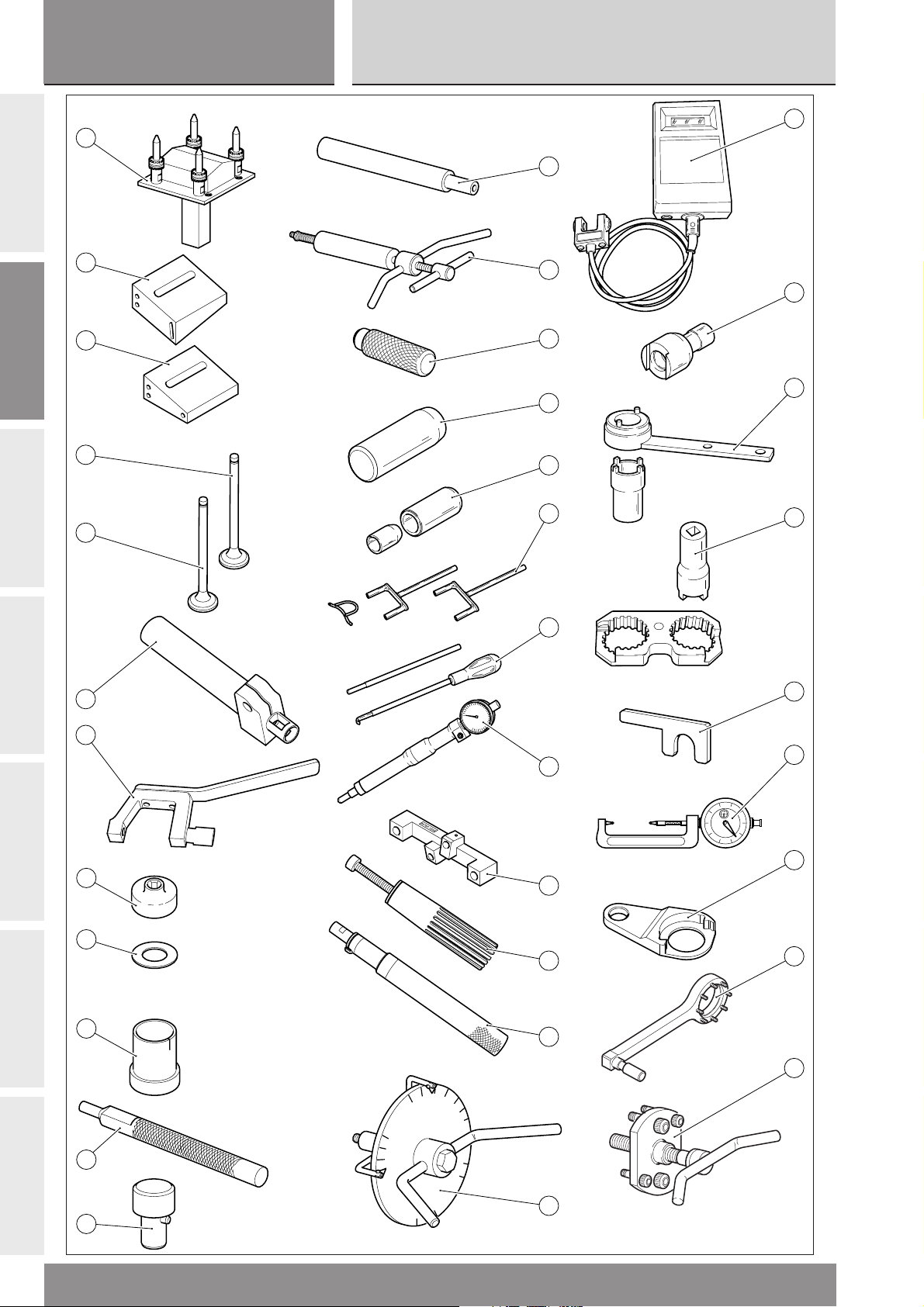
ATTREZZI SPECIALI
1) 041.1.049.1A Base per montaggio testa
999RS04
Interventi raccomandati
Maintenance schedule
A
B
C
2) 88763.1352 Attrezzo misura profondità sacche valvole aspirazione
3) 88763.1353 Attrezzo misura profondità sacche valvole scarico
4) 88765.1271 Valvola calibro aspirazione
5) 88765.1272 Valvola calibro scarico
6) 041.1.055.1A Attrezzo per assestare i semiconi
7) 041.1.056.1A Attrezzo per togliere i registri chiusura
8) 88765.1129 Calibro per controllo registri apertura
9) 713.1.014.1D Rondella rasamento di servizio
10) 88765.1316 Attrezzo misira gap segmenti
11) 041.1.107.1A Attrezzo montaggio SPIRE SPIROL
12) 041.1.080.1A Attrezzo rotazione camme
13) 041.1.038.1A Atrezzo assestamento anellini
14) 88713.1994 Estrattore per perni bilanciere
15) 88713.1980 Punzone piantaggio scodellini su alberi
D
E
F
16) 88713.2066 Attrezzo montaggio tappi chiusura camme
17) 88713.1906 Attrezzo per montare anelli di tenuta su alberi a cammes
18) 88713.2068 Kit per caricare bilancieri di chiusura
19) 88713.2069 Kit per tensionare molle bilancieri
20) 88765.1188 Calibro controllo P.M.S.
21) 041.1.034.1A Calibro alzata valvola cilindro orizzontale
22) 041.1.235.1B Canaletta per montaggio segeer cambio
23) 041.1.079.1C Attrezzo montaggio anelli pistone
24) 88713.2207 Attrezzo porta disco graduato per controllo anticipo con disco
25) 041.1.014.1A Frequenzimetro “CLAVIS BELT TENSIONMETER-TYPE”
26) 88713.1821 Chiave serraggio perni tenditori
27) 88713.1805 Attrezzo serraggio puleggia motrice
28) 88713.1806 Attrezzo di reazione per serraggio pulegge
29) 88713.1309 Spessimetro a forchetta 2,35 mm
G
30) 88713.1781 Micrometro serraggio bielle
31) 041.1.078.1A Attrezzo per serraggio ingranaggio primaria
32) 041.1.075.1A Chiave ferma alternatore per bloccaggio dado
33) 88713.1749 Estrattore per puleggia motrice
36
999RS - M.Y. 2004 - edizione/edition 01
Page 37

Ricomposizione motore
sezione / section
B
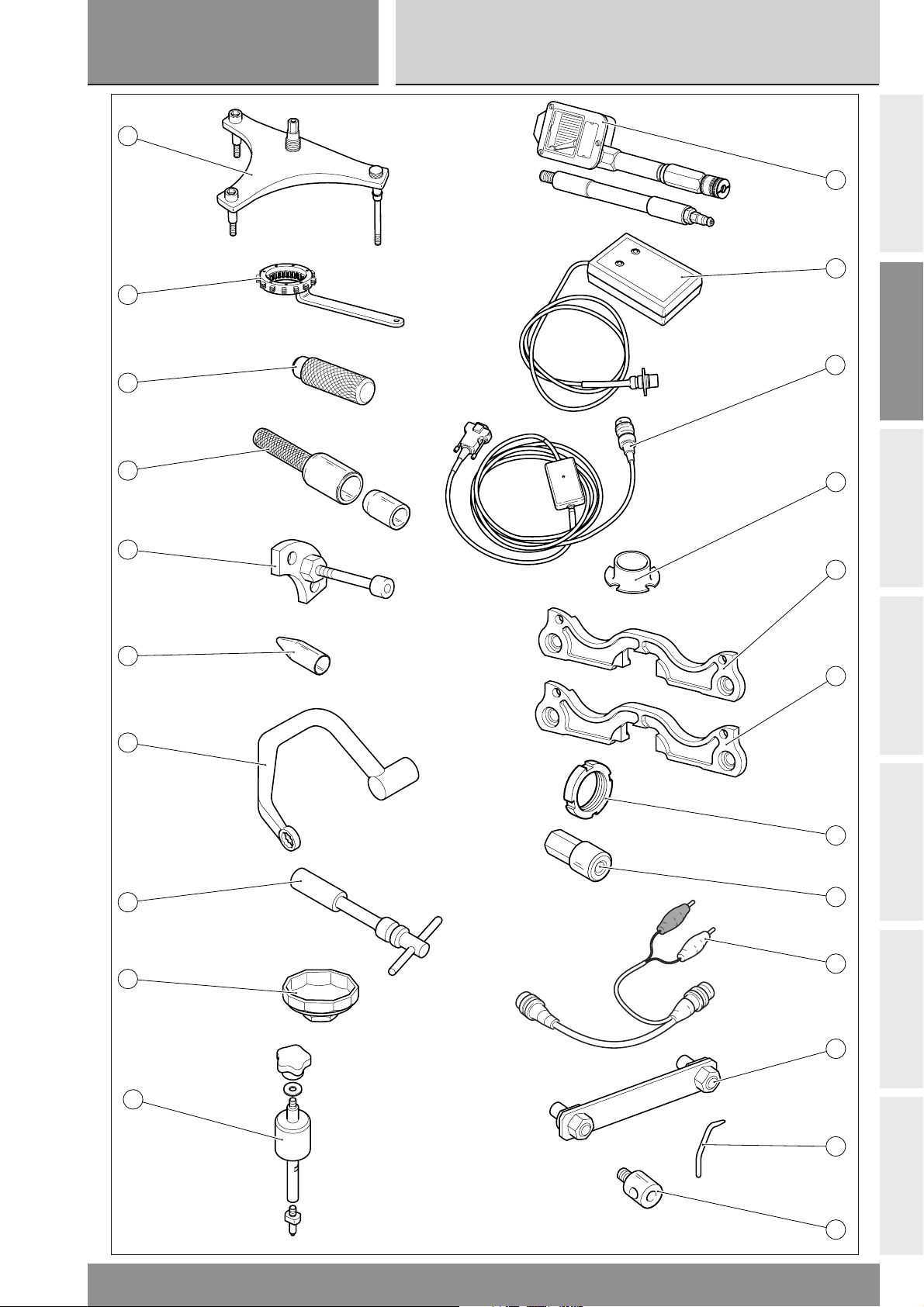
34) 041.1.032.2A Attrezzo per estrarre il coperchio frizione
35) 88713.0146 Chiave ferma campana tamburo frizione
999RS04
Interventi raccomandati
Engine reassembly
Maintenance schedule
36) 88713.2012 Attrezzo per montaggio controfaccia
37) 88713.2163 Attrezzo per piantaggio anello tenuta
38) 88713.1091 Piastrino per posizionamento forcella innesto marce
39) 88713.1920 Attrezzo inserimento anelli OR su prigionieri
40) 88713.2096 Chiave per bloccaggio dadi testa
41) 88713.1914 Chiave per candele
42) 0675.03.210 Chiave smontaggio cartuccia olio
43) 047.1.070.1A Estrattore spine nonio
44) 041.1.050.1A Attrezzo per prova compressione
45) 286.1.025.1A Centralina taratura leva cambio
46) 510.1.140.1A Cablaggio programmazione
47) 041.1.029.2A Protezione per biella
48) 041.1.047.1A Attrezzo fasatura spine SPIROL
49) 041.1.048.1A Attrezzo fasatura spine SPIROL
A
B
C
50) 703.1.028.1A Ghiera
51) 041.1.058.1A Attrezzo per il serraggio dei prigionieri nel carter
52) 510.1.232.2A Cablaggio taratura potenziometri
53) 041.1.179.1A Attrezzo per bloccare le pulegge
54) 88765.1266 Tastatore per comparatore alzata valvole
55) 041.1.222.1A Prolunga per comparatore
D
E
F
999RS - M.Y. 2004 - edizione/edition 01
G
37
Page 38

sezione / section
B
SPECIAL TOOLS
1) 041.1.049.1A Head mounting base
999RS04
Interventi raccomandati
Maintenance schedule
A
B
C
2) 88763.1352
3) 88763.1353
4) 88765.1271 Master gauge for intake valve
5) 88765.1272 Master gauge for exhaust valve
6) 041.1.055.1A Tool to fit valve collets
7) 041.1.056.1A Tool to remove closing shims
8) 88765.1129 Gauge to check opening shim
9) 713.1.014.1D Service shim
10) 88765.1316 Piston rings gap gauge
11) 041.1.107.1A SPIROL pins fitting tool
12) 041.1.080.1A Camshaft rotation tool
13) 041.1.038.1A Ring settling tool
14) 88713.1994 Rocker arm shaft puller
15) 88713.1980 Drift to drive retainers on shafts
Tool to measure intake valve pockets depth
Tool to measure exhaust valve pockets depth
D
E
F
16) 88713.2066 Tool to fit cam blanking caps
17) 88713.1906 Tool to fit seals on camshafts
18) 88713.2068 Closing rocker arm pre-load kit
19) 88713.2069 Rocker arm spring pre-load kit
20) 88765.1188 T.D.C. control gauge
21) 041.1.034.1A Horizontal cylinder valve lift gauge
22) 041.1.235.1B Tool to fit gearbox circlips
23) 041.1.079.1C Tool to fit piston rings
24) 88713.2207 Degree wheel holder tool to check ignition advance
25) 041.1.014.1A Frequency meter “CLAVIS BELT TENSIONMETER-TYPE”
26) 88713.1821 Wrench to tighten tensioner pins
27) 88713.1805 Drive roller tightening tool
28) 88713.1806 Reaction tool to tighten belt rollers
29) 88713.1309 Fork feeler gauge 2.35 mm
G
30) 88713.1781 Micrometer to tighten connecting rods
31) 041.1.078.1A Primary drive gear tightening tool
32) 041.1.075.1A Generator locking tool for nut tightening
33) 88713.1749 Drive roller puller
38
999RS - M.Y. 2004 - edizione/edition 01
Page 39

Ricomposizione motore
sezione / section
B
34) 041.1.032.2A Piston cover removal tool
35) 88713.0146 Clutch drum housing locking wrench
999RS04
Interventi raccomandati
Engine reassembly
Maintenance schedule
36) 88713.2012 Tool to fit counter - washer
37) 88713.2163 Seal ring driving tool
38) 88713.1091 Gear selector fork plate
39) 88713.1920 Tool to fit OR seals onto stud bolts
40) 88713.2096 Head nuts wrench
41) 88713.1914 Spark plug tool
42) 0675.03.210 Wrench to remove oil filter cartridge
56) 047.1.070.1A Nonius pin puller
44) 041.1.050.1A Compression test tool
45) 286.1.025.1A Gear change lever calibration CPU
46) 510.1.140.1A Programming wiring
47) 041.1.029.2A Protection for connecting rod
48) 041.1.047.1A SPIROL pins timing tool
49) 041.1.048.1A SPIROL pins timing tool
A
B
C
50) 703.1.028.1A Ring nut
51) 041.1.058.1A Tool to tighten stud bolts to casing
52) 510.1.232.2A Throttle position sensor calibration wiring
53) 041.1.179.1A Belt rollers locking tool
54) 88765.1266 Valve lift dial gauge stylus
55) 041.1.222.1A Dial gauge extension
D
E
F
999RS - M.Y. 2004 - edizione/edition 01
G
39
Page 40
sezione / section
B
999RS04
Interventi raccomandati
Maintenance schedule
A
B
C
1
2
3
11
8
14
9
10
D
E
F
4
12
5
15
6
13
7
G
40
999RS - M.Y. 2004 - edizione/edition 01
Page 41

Ricomposizione motore
sezione / section
B
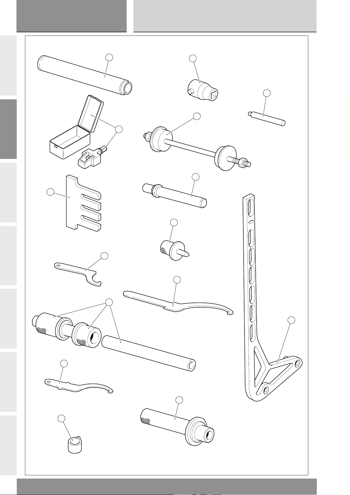
ATTREZZI SPECIALI
1) 88713.1072 Tampone piantaggio semicuscinetto base di sterzo
999RS04
Interventi raccomandati
Engine reassembly
Maintenance schedule
2) 88713.1964 Attrezzo montaggio catena
3) 041.1.021.1A Piastra ferma pastiglie freno
4) 88713.1043 Chiave per ghiera di sterzo
5) 88713.1135 Attrezzo montaggio cuscinetti a sfere del forcellone
6) 88713.1037 Chiave regolazione cannotto di sterzo
7) 041.1.006.1A Goniometro regolazione avanzamento
8) 88713.1865 Chiave perno ruota anteriore
9) 88713.1062 Attrezzo montaggio cuscinetti del cannotto di sterzo
10) 88713.1071 Tampone montaggio cuscinetti a rullini del bilanciere
11) 88765.1177 Bussola misura per telaio
12) 88713.1867 Chiave regolazione mozzo eccentrico
13) 88713.1068 Tampone montaggio cuscinetti a rullini del forcellone
14) 88713.1057 Tampone introduzione del cuscinetto dell’ammortizzatore di sterzo
15) 041.1.187.1A Kit variazione assetto
A
B
C
D
E
F
999RS - M.Y. 2004 - edizione/edition 01
G
41
Page 42

sezione / section
B
SPECIAL TOOLS
1) 88713.1072 Drift to drive the bottom yoke half bearing
999RS04
Interventi raccomandati
Maintenance schedule
A
B
C
2) 88713.1861 Tool for fitting the swingarm
3) 041.1.021.1A Brake pads stop plate
4) 88713.1043 Tool for steering ring nut
5) 88713.1135 Tool to install swingarm ball bearings
6) 88713.1037 Wrench to adjust the steering tube
7) 041.1.006.1A Degree wheel for advance adjustment
8) 88713.1865 Wrench for front wheel shaft
9) 88713.1062 Tool to install the steering tube bearings
10) 88713.1071 Drift to install the rocker arm needle roller bearings
11) 88765.1177 Bush for frame measurement
12) 88713.1867 Wrench to adjust eccentric hub
13) 88713.1068 Drift to install swingarm needle roller bearings
14) 88765.1057 Drift to drive bearing into steering damper
15) 041.1.187.1A Kit to change motorcycle track alignment
D
E
F
G
42
999RS - M.Y. 2004 - edizione/edition 01
Page 43

Ricomposizione motore
sezione / section
B
CARATTERISTICHE PRODOTTI
I prodotti usati per il serraggio, la sigillatura e la lubrificazione degli elementi verranno rappresentati all'interno della
figura con un simbolo. La tabella riporta i simboli utilizzati e le caratteristiche relative ai vari prodotti.
999RS04
Interventi raccomandati
Engine reassembly
Maintenance schedule
Simbolo Caratteristiche Prodotto consigliato
Olio motore gradazione SAE 20W 60 SHELL
Viscosità cinematica a 40°C: 172,6 Cst Ducati Racing Oil M1854
Viscosità cinematica a 100°C: 24,4 Cst
Densità a 20°C: 0,893 Kg/l
Liquido speciale per sistemi idraulici DOT 4. SHELL
Advance Brake DOT 4
Olio per ingranaggi SAE 80-90 o prodotti specifici per catene SHELL Advance Chain o
con anelli OR. Advance Teflon Chain
A
B
C
D
E
GREASE A Grasso a base di litio, a fibra media, di tipo "multipurpose". SHELL Alvania R3
GREASE B Grasso al bisolfuro di molibdeno resistente ad estreme SHELL Retinax HDX2
sollecitazioni meccaniche e termiche.
GREASE C Grasso per cuscinetti e articolazioni sottoposti a prolungate SHELL Retinax LX2
sollecitazioni meccaniche. Temperatura di utilizzo da –10 a 110 °C.
GREASE D Grasso con proprietà protettive, anticorrosive e di idrorepellenza. SHELL Retinax HD2
GREASE E Grasso per viti di biella in titanio PANKL PLB07
A
B
C
F
1
LOCK
2
LOCK
3
LOCK
4
LOCK
5
LOCK
6
LOCK
7
LOCK
GREASE F Grasso a base di vasellina con alta percentuale di MoS2 , adatto ROCOL DRY
ad evitare il verificarsi di rigature e graffiature sugli organi da MOLY PASTE
assemblare, resistente ad alti carichi (fino a 7000 kg/cm
a alte temperature (fino a 450 C°)
LOCK 1 Frenafiletti a debole resistenza meccanica. LOCTITE 222
LOCK 2 Frenafiletti a media resistenza meccanica. LOCTITE 243
LOCK 3 Frenafiletti ad alta resistenza meccanica per sigillatura di LOCTITE 270
parti filettate.
LOCK 4 Sigillante per piani ad alta resistenza meccanica e ai solventi. LOCTITE 510
Resiste ad alte temperature (fino a 200 °C), sigilla pressioni fino
a 350 Atm e colma giochi fino a 0,4 mm.
LOCK 5 Adesivo strutturale permanente per accoppiamenti cilindri a LOCTITE 648
scorrimento libero o filettati su parti meccaniche. Alta resistenza
meccanica ed ai solventi. Temperatura di utilizzo da –55 a 175 °C.
LOCK 6 Sigillante di tubazioni e raccorderie medio-grandi, per acqua e LOCTITE 577
ogni tipo di gas (ad eccezione dell'ossigeno). Massima capacità
di riempimento: 0,40 mm (gioco diametrale).
LOCK 7 Adesivo istantaneo gomma - plastica, con base etilica caricato LOCTITE 480
ad elastomeri.
2
) ed
D
E
F
8
LOCK
9
LOCK
10
LOCK
999RS - M.Y. 2004 - edizione/edition 01
LOCK 8 Bloccante permanente di parti filettate, cuscinetti, bussole, LOCTITE 601
scanalati e chiavette. Temperatura di esercizio da –55 a 150 °C.
LOCK 9 Bloccante per parti cilindriche con giochi fino a 0,25 mm e con LOCTITE 638
elevatissima resistenza a temperatura ambiente.
LOCK 10 Bloccante per parti cilindriche con giochi fino a 0,25 mm e con LOCTITE 620
elevatissima resistenza fino a 150 °C.
G
43
Page 44

sezione / section
B
Simbolo Caratteristiche Prodotto Consigliato
A
B
PRODUCT SPECIFICATIONS
Symbols inside the diagram show the type of threadlocker, sealant or lubricants to be used at the points indicated. The
table below shows the symbols together with the specifications for the threadlockers, sealants and lubricants to be used.
Symbol Specifications Advised product
Interventi raccomandati
999RS04
Guarnizione liquida siliconica, rsistente a temperature comprese THREE BOND
tra -60°C e + 250°C con ottima resistenza a pressione, urti,
vibrazioni, benzina, olio ed acqua.
Pasta sigillante per tubi di scarico. Autosigillante si indurisce al calore
e resiste a temperature superiori a 1000 °C.
Spray impiegato nel trattamento degli impianti elettrici. Rimuove SHELL
umidità e condensa e offre alta resistenza alla corrosione. Advance Contact Cleaner
Idrorepellente.
Maintenance schedule
C
D
E
A
B
C
D
E
F
Engine oil - Grade SAE 20W 60 SHELL
Kinematic viscosity at 40°C: 172.6 Cst Ducati Racing Oil M1854
Kinematic viscosity at 100°C: 24.4 Cst
Density at 20°C: 0.893 Kg/l
DOT 4 special hydraulic brake fluid. SHELL
Advance Brake DOT 4
SAE 80-90 gear oil or special products for chains with O-rings. SHELL Advance Chain or
Advance Teflon Chain
GREASE A Multipurpose, medium fibre, lithium grease. SHELL Alvania R3
GREASE B Molybdenum disulphide grease, high mechanical stress and high SHELL Retinax HDX2
temperature resistant.
GREASE C Bearing/joint grease for parts subject to prolonged SHELL Retinax LX2
mechanical stress. Temperature range: -10 to 110°C.
GREASE D Protective grease. Corrosion protectant, waterproof. SHELL Retinax HD2
GREASE E Grease for titanium con-rod bolts PANKL PLB07
GREASE F Vaseline grease with a high MoS2 percentage, suitable to ROCOL DRY
avoid scores and scrapes on the parts to be assembled, MOLY PASTE
resistant to high loads (up to 7000 kg/sq. cm.) and high
temperatures (up to 450 °C)
F
G
44
1
LOCK
2
LOCK
3
LOCK
4
LOCK
LOCK 1 Low-strength threadlocker. LOCTITE 222
LOCK 2 Medium-strength threadlocker. LOCTITE 243
LOCK 3 High-strength thread sealant for threaded parts. LOCTITE 270
LOCK 4 Flange sealant. Resistant to high mechanical stress, solvents LOCTITE 510
and high temperatures (up to 200°C). For pressures up
to 350 Atm. Fills gaps up to 0.4 mm.
999RS - M.Y. 2004 - edizione/edition 01
Page 45

Ricomposizione motore
sezione / section
B
Symbol Specifications Advised product
999RS04
Interventi raccomandati
Engine reassembly
Maintenance schedule
5
LOCK
6
LOCK
7
LOCK
8
LOCK
9
LOCK
10
LOCK
LOCK 5 Permanent adhesive for smooth or threaded cylindrical fasteners LOCTITE 648
on mechanical parts. High resistance to mechanical stresses
and solvents.Temperature range: -55 to 175°C.
LOCK 6 Pipe sealant for pipes and medium to large fasteners. LOCTITE 577
For water and gases (except oxygen). Maximum filling capacity:
diameter gaps up to 0.40 mm.
LOCK 7 Speed bonder for rubber and plastics. Elastomer loaded LOCTITE 480
ethylic base.
LOCK 8 High-strength retaining compound for threaded parts, bearings, LOCTITE 601
bushes, splines and keys. Temperature range: -55 to 150°C.
LOCK 9 Retaining compound for tapered parts. Fills gaps until 0.25 mm. LOCTITE 638
Highly resistant at ambient temperature.
LOCK 10 Product for sealing parallel couplings with gaps up to 0.25 mm. LOCTITE 620
Resistant to high temperature up to 150 °C
Sylicon fluid gasket, resistant to temperatures between THREE BOND
-60°C and + 250°C. Highly resistant to pressure, shocks,
vibrations, fuel, oil and water.
Exhaust pipe paste. Self-curing sealant, hardens when heated.
For temperatures over 1000°C.
Spray used in treating electrical systems to eliminate moisture SHELL
and condensation. Provides high resistance to corrosion. Advance Contact Cleaner.
Waterproof.
A
B
C
D
E
F
999RS - M.Y. 2004 - edizione/edition 01
G
45
Page 46

sezione / section
B
COPPIE DI SERRAGGIO MOTORE
applicazione filettatura Nm note
A
Dadi teste M10x1,5 1) Ingrassare sottodado, rosetta e filetto con
Viti biella M9x1 1) Svitare le viti della biella. Sgrassare i filetti della
B
Dado di fissaggio ingranaggio albero motore M25x1,5 1) Ingrassare sottotesta dado con GREASE F
999RS04
Interventi raccomandati
Maintenance schedule
/passo tolleranza ±5%
GREASE F
2) Avvicinare a 15 Nm
3) Avvicinare a 25 Nm
4) Serrare a 44 Nm
biella e delle viti con con DET AT/Ai CR mediante
scovolini
2) Lubrificare vite e sottotesta con GREASE E
3) Serrare per avvicinamento con allungamento di
0,050±0,005 mm
4) Proseguire il serraggio fino alla lettura di un
allungamento pari a 0,175±0,005 mm
2) Serrare a 200 Nm
3) Eseguire doppia ribaditura anti-svitamento
C
D
E
Dado rotore alternatore M24x1 270 GREASE F da mettere sotto la testa nel collo
Dado tamburo frizione M25x1,5 130 GREASE F da mettere sotto la testa nel collo
Eseguire ribaditura anti-svitamento
Dado ingranaggio albero rinvio distribuzione M14x1 80 LOCK 5 + doppia ridaditura anti-svitamento
Ghiera pulegge distribuzione su rinvio M15x1 80 GREASE B
Ghiera pulegge distribuzione su teste M17x1 80 GREASE B
Perni tenditore fisso e mobile M20x1 50 LOCK 2
Vite ferma cuscinetto tenditore fisso M14x2 50 GREASE F
Vite campana frizione M8x1,25 40 THREE BOND
Viti cannotto candela (Titanio) M6x1 12 LOCK 2
Candela accensione M10x1 12
Tappo ex posizionatore folle su tamburo cambio M18x1,5 25
Vite forata mandata olio carter in acciaio M8x1,25 18
Viti unione carter (Titanio) M8x1,25 25
Viti unione carter (Titanio) M6x1 12
F
G
Vite speciale unione carter cilindro oriz. gambo M7x1 15
scaricato
Viti ferma cuscinetto primario cambio (Titanio) M6x1 12 LOCK 2
Tappo by-pass pompa M15x1 20
Tappo su coperchio pompa acqua M10x1 20 Legatura di sicurezza
Tappo condotto aspirazione olio (Alluminio) M14x1,5 24 LOCK 8
Viti piastrino cuscinetto cambio M6x1 12 LOCK 2
Tappo esterno galleria olio M10x1,5 20 LOCK 8
Nipplo filtro olio in acciaio M16x1,5 40 LOCK 2
46
999RS - M.Y. 2004 - edizione/edition 01
Page 47

Ricomposizione motore
sezione / section
B
applicazione filettatura Nm note
Tappo scarico olio con calamita (Alluminio) M12x1,5 20 THREE BOND
Vite forata mandata olio alle teste M10x1 12 Legatura di sicurezza
Filtro olio a cartuccia M16x1,5 11 Ungere la guarnizione
Cappellotto sfiato M40x1,5 40 THREE BOND
Viti ferma cuscinetto pompa acqua (Titanio) M6x1 12 LOCK 2
999RS04
Interventi raccomandati
Engine reassembly
Maintenance schedule
/passo tolleranza ±5%
Legatura di sicurezza
con olio motore
A
Viti fissaggio cartelle laterali (Titanio) M6x1 12
Dado fissaggio tenditore mobile (Titanio) M8x1,25 25
Tappo ispezione sensore pick-up M12x1 20 THREE BOND
Bocchettone mandata acqua M22x1,5 25 THREE BOND
Bocchettone aspirazione acqua M30x1,5 25 THREE BOND
Viti raccordi entrata acqua ai cilindri (Titanio) M6x1 12
Vite fissaggio levetta fermo-marce M8x1,25 25 LOCK 2
Viti coperchio alternatore (Titanio) M6x1 12
Viti coperchio frizione (Titanio) M6x1 12
Viti corpo pompa olio (Titanio) M8x1,25 25
Viti corpo pompa olio M6x1 12
Viti TCEIR coperchio pompa olio M6x1 10
Viti coperchi testa in acciaio M6x1 10
Grano centraggio coperchio testa verticale M6x1 12 LOCK 2
B
C
D
Viti raccordo uscita acqua dalle teste (Titanio) M6x1 12
Viti pick-up (Titanio) M5x0,8 8 * THREE BOND
Vite 12,9 fissaggio volano - rotore DENSO M6x1 18 LOCK 2
Viti fissaggio statore DENSO (Titanio) M6x1 12 LOCK 2
Prigionieri testa (Acciaio) M10x1,5 25 LOCK 2
Prigionieri flangie scarico M6x1 10 LOCK 2
Prigionieri in acciaio per fissaggio coperchio M6x1 12 LOCK 2
testa verticale (al centro del cappelli camme)
Viti fissaggio cappelli camme in acciaio M8x1,25 Avvicinare a 10 Nm Ingrassare filetto con
Serrare a 22 Nm grasso GREASE F
Vite fissaggio coperchio filtro a rete (Titanio) M6x1 12 Legatura di sicurezza
Vite forata tubi olio alle teste su coperchio frizione M10x1 12 Legatura di sicurezza
Tappo su condotto olio lato M10x1 15
aspirazione teste
Dado eccentrico leva cambio M6x1 10 LOCK 9
E
F
G
999RS - M.Y. 2004 - edizione/edition 01
47
Page 48

sezione / section
B
applicazione filettatura Nm note
Vite STEI foro inclinato doppia presa M6x1 5 LOCK 8 + cianfrinatura
A
di pressione su coperchio frizione
Tappo su foro inclinato albero motore M10x1 30 Loctite 620
Nipplo sensore di pressione su coperchio frizione M10x1 14 Loctite 620 e legatura di
Tappo condotto inclinato olio su coperchio frizione M10x1 20 LOCK 8 e legatura di
999RS04
Interventi raccomandati
Maintenance schedule
/passo tolleranza ±5%
sicurezza + three bond
sotto rosetta
sicurezza
B
C
D
M5x0,8 8 *
M6x1 10
M6x1 12
Viti e dadi in generale
(Acciaio e Titanio) M8x1,25 25
M10x1,5 35
M12x1,75 55
* La coppia di serraggio eccede il 70% della sigma 0,2
E
F
G
48
999RS - M.Y. 2004 - edizione/edition 01
Page 49

Ricomposizione motore
sezione / section
B
ENGINE TORQUE SETTINGS
part thread Nm notes
Head nuts M10x1.5 1) Smear underhead, washer and thread with
Con-rod bolts M9x1 1) Loosen con-rod bolts. Degrease con-rod and
Crankshaft gear locking nut M25x1.5 1) Grease nut underhead with GREASE F
999RS04
Interventi raccomandati
Engine reassembly
Maintenance schedule
/pitch tolerance ±5%
GREASE F
2) Snug to 15 Nm
3) Snug to 25 Nm
4) Tighten to 44 Nm
screw threads with DET AT/Ai CR and brushes
2) Lubricate screw and underhead with GREASE E
3) Tighten for snugging with a stretch of
0.050±0.005 mm
4) Continue tightening until reading a stretch of
0.175±0.005 mm
2) Tighten to 200 Nm
3) Double rivet to prevent loosening
A
B
Generator rotor nut M24x1 270 GREASE F under head.
Clutch drum nut M25x1.5 130 GREASE F under head.
Rivet to prevent loosening
Timing layshaft gear nut M14x1 80 LOCK 5 + Double rivet to prevent loosening
Ring nut for belt rollers on transmission shaft M15x1 80 GREASE B
Ring nut for timing belt rollers on head M17x1 80 GREASE B
Mobile and fixed tensioner pins M20x1 50 LOCK 2
Fixed tensioner bearing locking screw M14x2 50 GREASE F
Clutch housing screw M8x1.25 40 THREE BOND
Spark plug tube screws (Titanium) M6x1 12 LOCK 2
Spark plug M10x1 12
Former neutral positioner plug on gearbox drum M18x1.5 25
Casing drilled screw in steel (for oil delivery) M8x1.25 18
Casing jointing screws (Titanium) M8x1.25 25
Casing jointing screws (Titanium) M6x1 12
C
D
E
Horizontal cylinder casing jointing special screw M7x1 15
(waisted shank)
Gearbox primary bearing stop screws (Titanium) M6x1 12 LOCK 2
By-pass pump plug M15x1 20
Water pump cover plug M10x1 20 Safety binding
Oil intake duct plug (Aluminum) M14x1.5 24 LOCK 8
Gearbox bearing stop plate screws M6x1 12 LOCK 2
Oil duct outer plug M10x1.5 20 LOCK 8
Oil filter nipple (steel) M16x1.5 40 LOCK 2
999RS - M.Y. 2004 - edizione/edition 01
F
G
49
Page 50

sezione / section
B
part thread Nm notes
Oil drain plug with magnet (Aluminum) M12x1.5 20 THREE BOND
A
Drilled screw for oil delivery to heads M10x1 12 Safety binding
Oil cartridge filter M16x1.5 11 Smear seal with
Oil breather cover M40x1.5 40 THREE BOND
Coolant pump bearing stop screws (Titanium) M6x1 1 2 LOCK 2
999RS04
Interventi raccomandati
Maintenance schedule
/pitch tolerance ±5%
Safety binding
engine oil
B
C
D
Side cover fixing screws (Titanium) M6x1 12
Mobile tensioner fixing nut (Titanium) M8x1.25 25
Pick-up sensor inspection cap M12x1 2 0 THREE BOND
Coolant delivery union M22x1.5 2 5 THREE BOND
Coolant intake union M30x1.5 2 5 THREE BOND
Screws of water inlet fittings to cylinder (Titanium) M6x1 12
Gear stop lever retaining screw M8x1.25 25 LOCK 2
Generator cover screws (Titanium) M6x1 1 2
Clutch cover screws (Titanium) M6x1 1 2
Oil pump body screws (Titanium) M8x1.25 25
Oil pump body screws M6x1 1 2
TCEIR oil pump cover screws M6x1 10
Head cover screws (steel) M6x1 10
Vertical head cover centering dowel M6x1 12 LOCK 2
E
F
G
Retaining screws for water outlet from heads M6x1 12
Pick-up screws (Titanium) M5x0.8 8 * THREE BOND
Flywheel - DENSO rotor 12.9 retaining screw M6x1 18 LOCK 2
DENSO stator retaining screws (Titanium) M6x1 1 2 LOCK 2
Head stud bolts (Steel) M10x1.5 25 LOCK 2
Exhaust flange stud bolts M6x1 10 LOCK 2
Steel stud bolts for vertical head cover M6x1 12 LOCK 2
(at the center of cam covers)
Cam caps retaining screws (steel) M8x1.25 Snug to 10 Nm Grease thread with
Tighten to 22 Nm GREASE F
Mesh filter cover retaining screw (Titanium) M6x1 12 Safety binding
Drilled screw for oil pipes to heads on clutch cover M10x1 12 Safety binding
50
999RS - M.Y. 2004 - edizione/edition 01
Page 51

Ricomposizione motore
sezione / section
B
part thread Nm notes
Plug on head-intake-side oil duct M10x1 15
Gear lever eccentric nut M6x1 10 LOCK 9
STEI screw with slanting hole, double M6x1 5 LOCK 8 + calking
pressure pick-up on clutch cover
Blanking plug onto crankshaft slanted hole M10x1 30 Loctite 620
Pressure sensor nipple on clutch cover M10x1 14 Loctite 620 and safety
Oil slanted channel plug onto clutch cover M10x1 20 LOCK 8 and safety binding
Screws and nuts in general
(Steel and Titanium) M8x1.25 25
999RS04
Interventi raccomandati
Engine reassembly
Maintenance schedule
/pitch tolerance ±5%
M5x0.8 8 *
M6x1 10
M6x1 12
binding + three bond
under washer
A
B
C
* Tightening torque exceeds 70% of sigma 0.2
M10x1.5 35
M12x1.75 55
D
E
999RS - M.Y. 2004 - edizione/edition 01
F
G
51
Page 52

sezione / section
B
COPPIE DI SERRAGGIO MOTOTELAIO
applicazione filettatura Nm note
A
Dado fissaggio corona 10x1,25 44 LOCK 2
Perno ruota posteriore 28x1,5 80 GREASE B
Vite fissaggio boccola filettata piedino forcella 5x0,8 7
Perno ruota anteriore 25x1,5 59 GREASE B sul filetto
Vite superiore ammortizzatore 10x1,25 35 GREASE B sul filetto
B
Vite inferiore ammortizzatore 10x1,25 35 GREASE B sul filetto
Vite superiore puntone sospensione 10x1,25 35 GREASE B sul filetto
Dado bilanciere sospensione al telaio 10x1,25 40 GREASE B sul filetto
Vite perno forcellone 15x1,25 70 GREASE B
999RS04
Interventi raccomandati
Maintenance schedule
(mm) Tolleranza ±5%
C
D
E
Vite fissaggio boccola filettata perno ruota post. 6x1 8 GREASE A
Vite testa di sterzo 8x1,25 15 GREASE B sul filetto
Vite base di sterzo 8x1,25 12 GREASE B sul filetto (1)
Tappo superiore perno sterzo 20x1,5 40 GREASE B sul filetto
Vite conica inferiore perno sterzo 26x1,5 60 GREASE B solo sul filetto
Vite fissaggio pinza freno anteriore 10x1,5 40 GREASE B sul filetto
Vite fissaggio cannotto di sterzo 8x1,25 18 GREASE B sul filetto
Vite fissaggio semimanubri 6x1 8 Grasso sul filetto (1)
Vite fissaggio morsetti semimanubri 6x1 8 GREASE B sul filetto (1)
Vite fissaggio semimanubri alla testa di sterzo 5x0,8 7 GREASE B sul filetto (1)
Vite fissaggio pompa frizione 6x1 8 GREASE B sul filetto
Vite fissaggio pompa freno anteriore 6x1 8 GREASE B sul filetto
Vite fissaggio pinza freno posteriore 7x1 18 LOCK 2
Vite fissaggio parafango posteriore 6x1 8 LOCK 2
F
G
Dado pignone 25x1,5 140 Doppia pigatura rosetta
GREASE B
Vite fissaggio telaietto posteriore 8x1,25 24
Ghiera cuscinetti di sterzo 35x1 20 Allentare 30°
Vite fissaggio ghiera registro cuscinetti sterzo 4x0,7 3
Dado fissaggio disco freno posteriore 8x1,25 24 LOCK 2
Vite fissaggio pattino catena 6x1 10 LOCK 2
Dado sferico fissaggio motore 12x1,25 40 GREASE B sul filetto
Vite supporto telaietto anteriore 6x1 8
52
999RS - M.Y. 2004 - edizione/edition 01
Page 53

Ricomposizione motore
sezione / section
B
applicazione filettatura Nm note
Vite fissaggio radiatore acqua 6x1 10 GREASE B sul filetto
Vite fissaggio radiatore olio 6x1 10 GREASE B sul filetto
Vite fissaggio disco freno anteriore 8x1,25 24
Raccordo freno 10x1 18
Raccordo tubo frizione 10x1 18
Vite snodo ammortizzatore sterzo su testa 7x1 15 LOCK 2
Tappo riferimento cannotto 12x1 18 GREASE B sul filetto
Vite piede forcella 8x1,25 15 GREASE B sul filetto (1)
Vite supporto scarico al telaietto 6x1 10 GREASE B sul filetto
Vite fissaggio supporto batteria 6x1 9
Vite supporto pompa freno posteriore 6x1 10 GREASE B sul filetto
999RS04
Interventi raccomandati
Engine reassembly
Maintenance schedule
(mm) Tolleranza ±5%
A
B
Vite supporto staffa pompa freno posteriore 10x1,5 34 GREASE B sul filetto
Perno leva freno posteriore 10x1,5 29 GREASE B sul filetto
Vite fissaggio supporto pedane al telaio 8x1,25 25 GREASE B sul filetto
Vite fissaggio snodo pedane 8x1,25 25 LOCK 2
Viti collettore aspirazione 6x1 8 Serraggio a mano
Viti chiusura fori laterali collettore aspirazione 6x1 12
Dadi flangia scarico 6x1 10
Sensore tamburo cambio 18x1,5 25 Serraggio a mano
Vite fissaggio comando gas 6x1 8
Vite fissaggio serbatoio freno posteriore 6x1 4 LOCK 2
Sensore temperatura acqua 6x1,5 7
Vite fissaggio bobina 4x0,7 3
Vite serbatoio frizione 4x0,7 3
Vite attacchi su serbatoio 5x0,8 7
C
D
E
Viti staffa radiatore acqua 6x1 12
Tubo benzina pompa 10x1 12
Tubo benzina filtro 12x1,5 25
Tubo benzina filtro 14x1,5 25
Raccordo rapido benzina 14x1 25 LOCK 2
Vite piastrina fissaggio iniettori 5x0,8 5 Legatura
Vite posizionamento doccia 5x0,8 7 Legatura
999RS - M.Y. 2004 - edizione/edition 01
F
G
53
Page 54

sezione / section
B
applicazione filettatura Nm note
Vite traversino rinforzo telaio 8x1,25 24
A
Viti e dadi in genere 5x0,8 5
Viti e dadi in genere 6x1 10
Viti e dadi in genere 8x1,25 23
Viti e dadi in genere 10x1,5 35
Viti e dadi in genere 12x1,75 55
B
(1)Sequenza di serraggio 1-2-1
(2) Sequenza di serraggio 1(UP) -2-1
(3) Non ingrassare il cono ma soltanto il filetto in minima parte.
(4) Contrastare con chiave radiatore
(5) Contrastare con nipplo
(6) Rispettare ordine di fissaggio iniziale
Interventi raccomandati
999RS04
Con dadi o ruote nuovi eseguire n° 10 serraggi di assestamento
Maintenance schedule
(mm) Tolleranza ±5%
C
D
E
F
G
54
999RS - M.Y. 2004 - edizione/edition 01
Page 55

Ricomposizione motore
sezione / section
B
FRAME TORQUE SETTINGS
part thread Nm notes
Rear sprocket nut 10x1.25 44 LOCK 2
Rear wheel shaft nut 28x1.5 80 GREASE B
Fork bottom end threaded bush screw 5x0.8 7
Front wheel shaft 25x1.5 59 GREASE B on thread
Rear shock absorber upper screw 10x1.25 35 GREASE B on thread
Rear shock absorber lower screw 10x1.25 35 GREASE B on thread
Suspension linkage upper screw 10x1.25 35 GREASE B on thread
Suspension rocker arm to frame fixing nut 10x1.25 4 0 GREASE B on thread
999RS04
Interventi raccomandati
Engine reassembly
Maintenance schedule
(mm) tolerance ±5%
A
B
Swingarm pivot bolt 15x1.25 70
Rear wheel shaft threaded bush screw 6x1 8 GREASE A
Steering head screw 8x1.25 15 GREASE B on thread
Bottom yoke screw 8x1.25 12 GREASE B on thread (1)
Steering tube upper cap 20x1.5 40 GREASE B on thread
Steering tube lower tapered screw 26x1.5 60 GREASE B on thread only
Front brake caliper screw 10x1.5 40 GREASE B on thread
Steering tube retaining screw 8x1.25 18 GREASE B on thread
Handlebar fixing screw 6x1 8 Grease on thread (1)
Handlebar clip fixing screw 6x1 8 GREASE B on thread (1)
Screw securing handlebars to steering head 5x0.8 7 GREASE B on thread (1)
Clutch master cylinder fixing screw 6x1 8 GREASE B on thread
Front brake master cylinder fixing screw 6x1 8 GREASE B on thread
Rear brake caliper fixing screw 7x1 18 LOCK 2
GREASE B
C
D
E
Rear mudguard fixing screw 6x1 8 LOCK 2
Sprocket nut 25x1.5 140 Double bend washer
GREASE B
Rear subframe fixing screw 8x1.25 24
Steering head bearing ring nut 35x1 20 Loosen by 30°
Steering head bearing adjusting ring nut fixing 4x0.7 3
screw
Rear brake disc fixing nut 8x1.25 24 LOCK 2
999RS - M.Y. 2004 - edizione/edition 01
F
G
55
Page 56

sezione / section
B
part thread Nm notes
Chain sliding shoe retaining screw 6x1 1 0 LOCK 2
A
Engine fixing ball nut 12x1.25 40 GREASE B on thread
Front subframe holder screw 6x1 8
Water radiator fixing screw 6x1 1 0 GREASE B on thread
Oil cooler fixing screw 6x1 10 GREASE B on thread
Front brake disc fixing screw 8x1.25 24
999RS04
Interventi raccomandati
Maintenance schedule
(mm) Tolerance ±5%
B
C
D
Brake coupling 10x1 18
Clutch line connector 10x1 18
Steering damper on head joint screw 7x1 15 LOCK 2
Steering tube reference plug 12x1 18 GREASE B on thread
Fork bottom end bolt 8x1.25 15 GREASE B on thread (1)
Exhaust support to subframe screw 6x1 1 0 GREASE B on thread
Battery mount fixing screw 6x1 9
Rear brake master cylinder support screw 6x1 1 0 GREASE B on thread
Rear brake master cylinder bracket support screw 10x1.5 34 GREASE B on thread
Rear brake lever pin 10x1.5 29 GREASE B on thread
Footpeg plate to frame retaining screw 8x1.25 25 GREASE B on thread
Footpeg joint retaining screw 8x1.25 25 LOCK 2
Intake manifold screws 6x1 8 Hand tightening
Intake manifold side holes blanking screws 6x1 12
E
F
G
Exhaust flange nuts 6x1 10
Gearbox drum sensor 18x1.5 25 Hand tightening
Throttle control screw 6x1 8
Rear brake reservoir fixing screw 6x1 4 LOCK 2
Coolant temperature sensor 6x1.5 7
Coil retaining screw 4x0.7 3
56
999RS - M.Y. 2004 - edizione/edition 01
Page 57

Ricomposizione motore
sezione / section
B
part thread Nm notes
Clutch reservoir screw 4x0.7 3
Tank connector screw 5x0.8 7
Radiator bracket screws 6x1 1 2
Fuel pump line 10x1 12
Fuel filter line 12x1.5 25
Fuel filter line 14x1.5 25
999RS04
Interventi raccomandati
Engine reassembly
Maintenance schedule
(mm) Tolerance ±5%
A
Fuel quick coupling 14x1 25 LOCK 2
Injectors fixing plate screw 5x0.8 5 Binding
Jet positioning screw 5x0.8 7 Binding
Frame reinforcement bar screw 8x1.25 24
Screws and nuts in general 5x0.8 5
Screws and nuts in general 6x1 10
Screws and nuts in general 8x1.25 23
Screws and nuts in general 10x1.5 3 5
Screws and nuts in general 12x1.75 5 5
(1) Tightening sequence: 1-2-1
(2) Tightening sequence: 1(UP) -2-1
(3) Do not grease cone. Slightly grease thread only.
When using new nuts or ring nuts, make 10 settling tightenings
(4) Hold with cooler wrench
(5) Hold with nipple
(6) Comply with the original fixing order
B
C
D
999RS - M.Y. 2004 - edizione/edition 01
E
F
G
57
Page 58

Page 59

Scomposizione motore
Engine disassembly
A
B
C
D
E
F
G
Page 60

sezione / section
C
999RS04
Scomposizione motore
Engine disassembly
INDICE DI SEZIONE
SCARICO OLIO
SCARICO LIQUIDO DI RAFFREDDAMENTO
A
CANDELE, CINGHIE E TENDITORI MOBILI
TESTE
CILINDRO E PISTONE
COPERCHIO ALTERNATORE
ALTERNATORE E VOLANO
B
INGRANAGGI COMANDO DISTRIBUZIONE
LEVERAGGIO SELEZIONE MARCE
FRIZIONE
COPERCHIO FRIZIONE
INGRANAGGIO CONDOTTO DELLA
C
TRASMISSIONE PRIMARIA E CAMPANA
FRIZIONE
SECTION INDEX
DRAINING OIL
61
DRAINING COOLANT
61
SPARK PLUGS, TIMING BELTS AND MOBILE
61
TENSIONERS
62
CYLINDER HEADS
63
CYLINDERS AND PISTONS
64
ALTERNATOR COVER
66
ALTERNATOR AND FLYWHEEL
67
TIMING GEARS
67
GEAR SELECTOR LEVER
68
CLUTCH
70
CLUTCH COVER
CLUTCH HOUSING AND PRIMARY
DRIVEN GEAR
71
61
61
61
62
63
64
66
67
67
68
70
71
POMPA OLIO
INGRANAGGIO ALBERO MOTORE DELLA
TRASMISSIONE PRIMARIA
PULEGGE RINVIO DISTRIBUZIONE
D
ACCESSORI BASAMENTO
PRIGIONIERI, BOCCOLE E GRANI DI
CENTRAGGIO
APERTURA CARTER
ELEMENTI INTERNI SEMICARTER
SCOMPOSIZIONE TESTE
E
F
OIL PUMP
72
CRANKSHAFT PRIMARY DRIVE GEAR
73
TIMING BELT ROLLERS
74
CRANKCASE FITTINGS
75
STUD BOLTS, CENTERING BUSHES AND
LOCATORS
76
OPENING THE CRANKCASE
77
CASINGS INNER PARTS
78
HEADS DISASSEMBLY
80
72
73
74
75
76
77
78
80
G
60
999RS - M.Y. 2004 - edizione/edition 01
Page 61
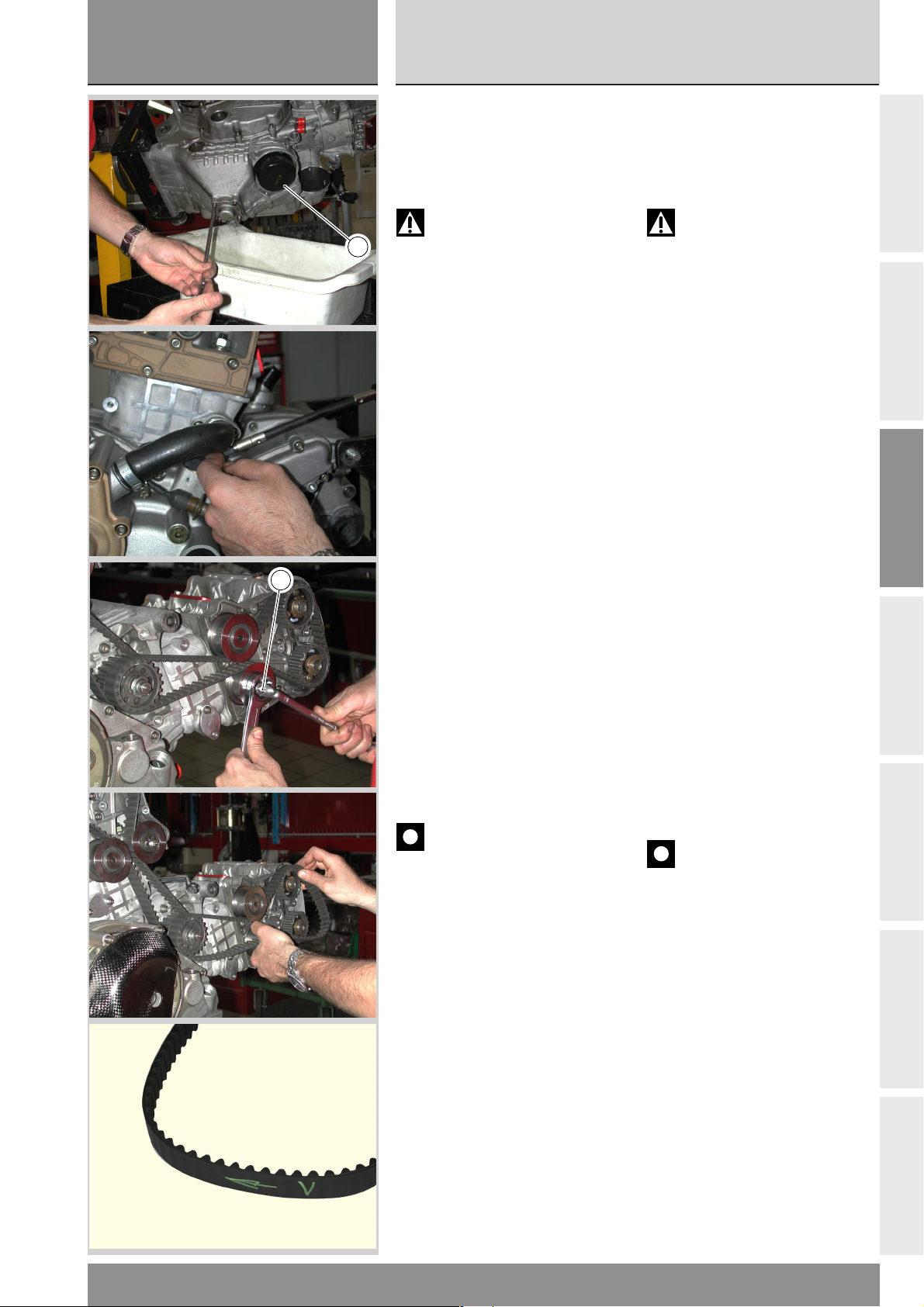
sezione / section
C
999RS04
Ricomposizione motore
Scomposizione motore
Engine reassembly
Engine disassembly
SCARICO OLIO
❍ Rimuovere le 4 viti di ritenzione
tappo filtro a rete, quindi rimuovere
il tappo e la relativa guarnizione.
❍
Rimuovere il filtro olio (1).
Attenzione
Non disperdere l’olio esausto
1
nell’ambiente.
SCARICO LIQUIDO DI
RAFFREDDAMENTO
❍ Svitare le viti dei raccordi di
mandata acqua dalla pompa ai
cilindri e lasciare drenare il liquido
contenuto nel motore.
❍ Rimuovere i manicotti di
collegamento pompa-cilindri.
DRAINING OIL
❍ Remove the 4 screws on the
mesh filter cap, then remove cap
and seal.
❍
Remove oil filter (1).
Warning
Do not dispose of used oil in
the environment.
DRAINING COOLANT
❍ Undo the screws on the unions
for coolant delivery from pump to
cylinders and allow engine fluid to
drain off.
❍ Remove pump-to-cylinders
connecting unions.
A
B
C
1
CANDELE, CINGHIE E
TENDITORI MOBILI
❍ Rimuovere le candele di
accensione.
❍ Allentare e rimuovere il dado di
fissaggio del tenditore mobile (1) e
sfilare contemporaneamente il
tenditore mobile e la cinghia.
● In caso di riutilizzo, praticare sulla
superficie esterna di ogni cinghia
una freccia indicante il senso di
rotazione (antiorario) ed un
riferimento indicante la testa sulla
quale è montata (“V” o “O”).
Importante
Piegature brusche (raggio
minimo di curvatura 20 mm), olio,
benzina o solventi danneggiano
irreparabilmente le cinghie dentate.
SPARK PLUGS, TIMING BELTS
AND MOBILE TENSIONERS
❍ Remove the spark plugs.
❍ Loosen and remove mobile
tensioner fixing nut (1) and, at the
same time, slide out mobile
tensioner and timing belt.
● If belts will be re-used after
disassembly, mark the outer face of
each belt with an arrow indicating
the direction of travel
(counterclockwise) and a letter
indicating the head on which the
belt is to be reassembled (e.g. “V”
for vertical or “O” for horizontal).
Caution
Tight bends (minimum radius
20 mm), oil, fuel or solvents cause
permanent damage to toothed belts.
D
E
F
999RS - M.Y. 2004 - edizione/edition 01
G
61
Page 62
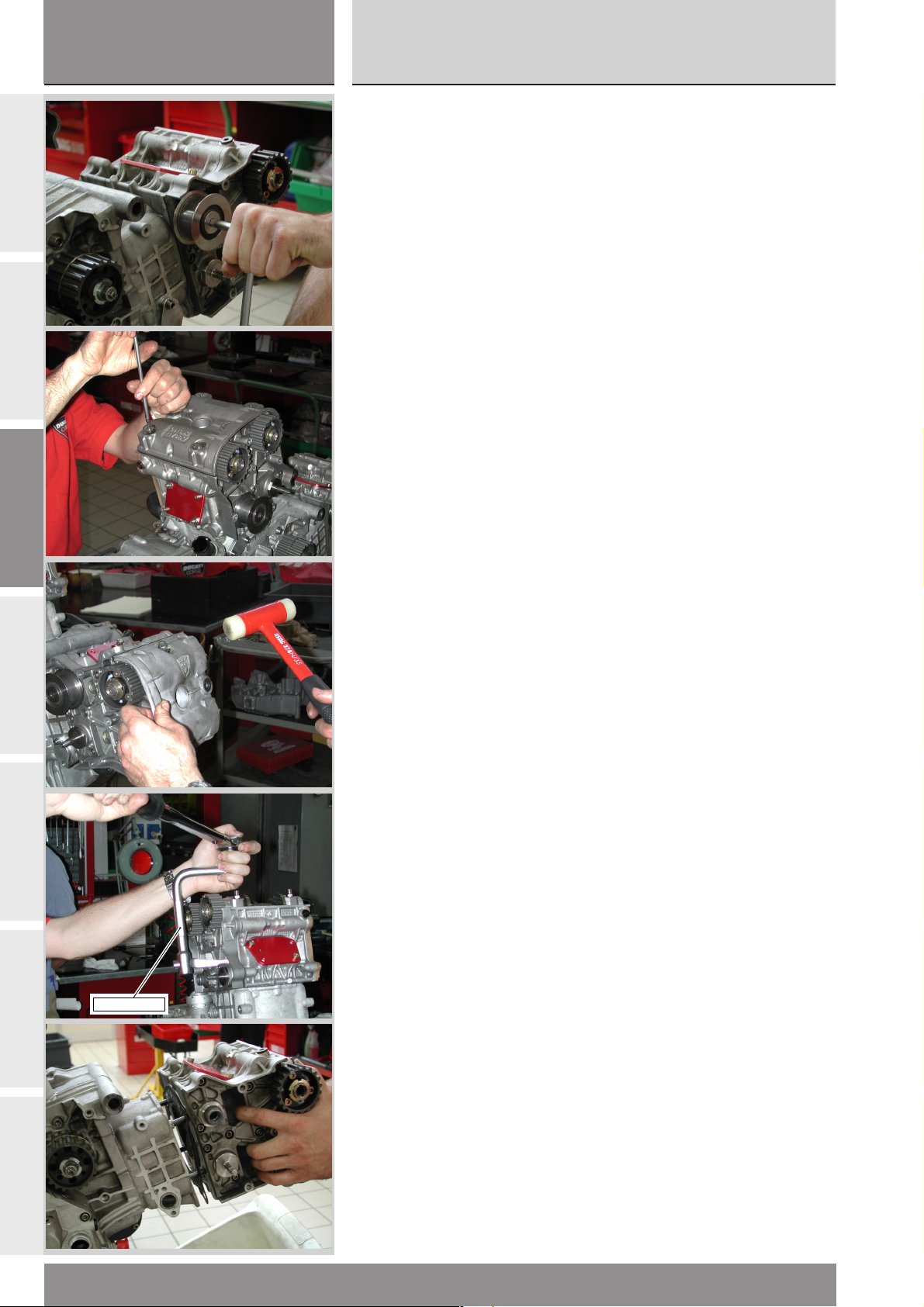
sezione / section
C
999RS04
Scomposizione motore
Engine disassembly
A
B
C
❍
Rimuovere il tenditore fisso.
TESTE
❍ Allentare e rimuovere le viti
coperchio testa.
❍
Rimuovere i coperchi teste
aiutandosi eventualmente con
qualche colpo di martello di plastica
senza danneggiarle.
❍
Rimuovere i raccordi acqua in
modo da svuotare completamente il
circuito di raffreddamento.
❍ Allentare, procedendo con
sequenza “a croce”, i dadi della
testa utilizzando la chiave cod.
88713.2096 abbinata ad una chiave
a cricchetto.
❍
Sfilare leggermente la testa.
❍
Rimuovere i dadi e le rosette
speciali.
❍
Sfilare la testa dai prigionieri.
❍ Remove fixed tensioner.
CYLINDER HEADS
❍ Loosen and remove head cover
screws.
❍
Remove head covers. Gently tap
with a plastic mallet if necessary.
❍
Remove coolant unions in order
to drain cooling circuit completely
off.
❍ Working crossways and using
wrench part no. 88713.2096 with a
ratchet wrench, loosen head nuts.
❍
Slightly slide head out.
❍
Remove nuts and special
washers.
❍
Remove head from stud bolts.
D
E
F
88713.2096
G
62
999RS - M.Y. 2004 - edizione/edition 01
Page 63
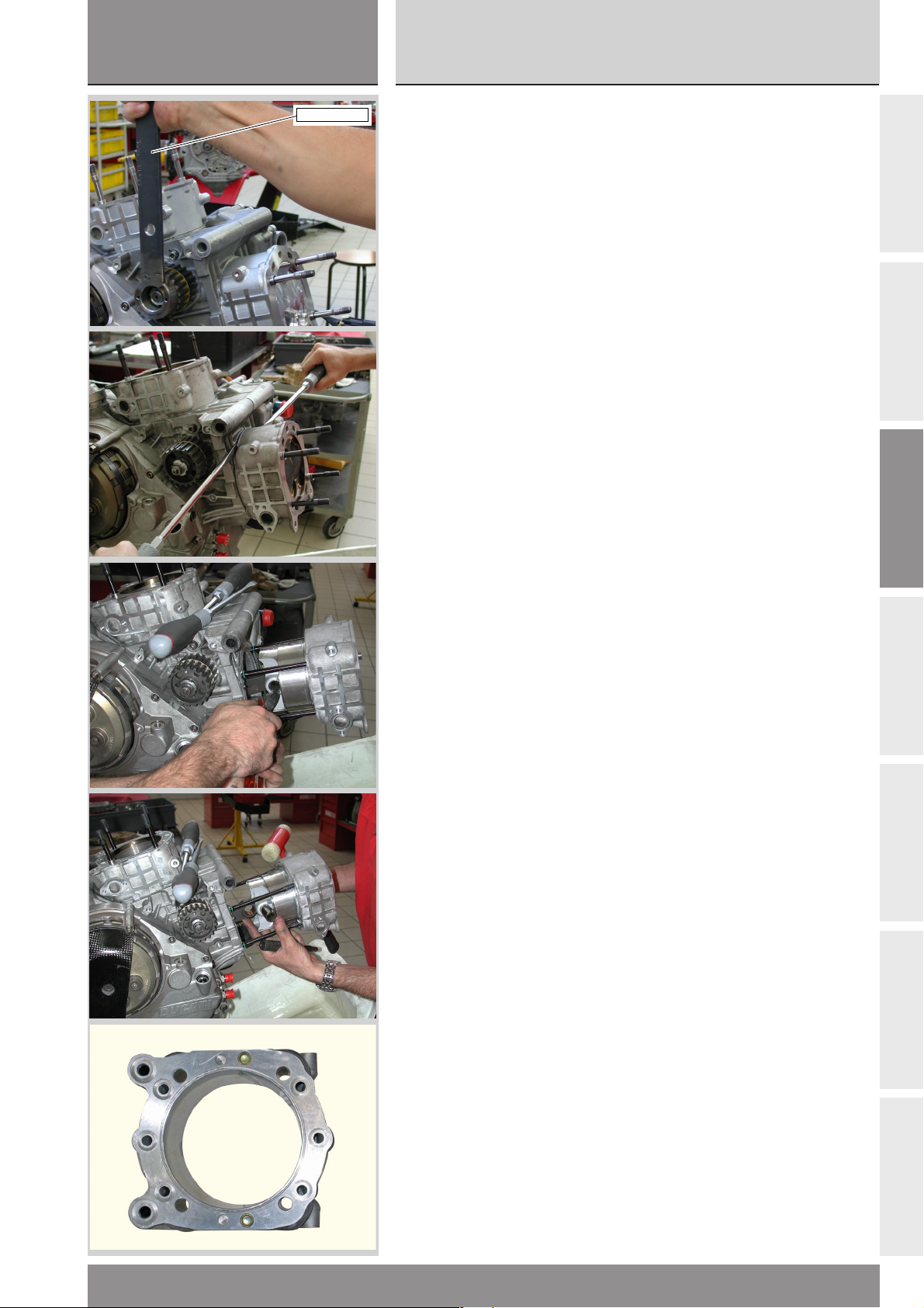
sezione / section
C
999RS04
Ricomposizione motore
Scomposizione motore
Engine reassembly
Engine disassembly
88713.1805
CILINDRO E PISTONE
❍ Rimuovere l’anello Willis
aiutandosi con un punteruolo
facendo attenzione a non rovinare la
sede sul cilindro
Si consiglia di sostituire l’anello
Willis ad ogni smontaggio.
● Portare il pistone del cilindro
orizzontale al punto morto superiore
ruotando le pulegge sull’albero di
rinvio distribuzione con la chiave
cod. 88713.1805. I perni della chiave
devono essere inseriti nei 2 fori non
filettati della puleggia.
❍ Sfilare delicatamente il cilindro,
aiutandosi con due grossi cacciaviti,
come in foto, quindi sollevarlo fino a
che risulti accessibile lo spinotto del
pistone.
❍ Rimuovere il fermo dello spinotto
dal lato frizione.
❍ Operando dal lato opposto, sfilare
lo spinotto quel tanto che basta da
disimpegnare la biella.
❍ Sfilare completamente dai
prigionieri il gruppo completo
pistone-cilindro. In caso di rimozione
del pistone dal cilindro
contrassegnare gli elementi per
poterli accoppiare nel rimontaggio.
● Portare il pistone del cilindro
verticale al punto morto superiore
ed agire analogamente al cilindro
orizzontale.
❍
Rimuovere dai cilindri le boccole
di centraggio.
● A questo punto è consigliabile
otturare le aperture del carter con
uno straccio per impedire che corpi
estranei possano cadere all’interno.
CYLINDERS AND PISTONS
❍ Remove the Willis ring with a
punch, pay attention not to damage
the seat on the cylinder. It is
recommended to change the Willis
ring every time it is removed.
● Move the horizontal cylinder
piston to top dead center by turning
the rollers of the timing layshaft with
the special tool part no. 88713.1805.
Insert the spanner pins in the two
unthreaded holes in the roller; do
not use the threaded holes.
❍ Using two large screwdrivers,
gently slide cylinder out as shown in
the picture. Then lift it until you gain
access to piston gudgeon pin.
❍ Remove the circlip from the
gudgeon pin on the clutch-side.
❍ Working from the other side,
move the gudgeon pin out until the
con-rod is released.
❍ Lift the piston-cylinder assembly
and remove it from the stud bolts. If
you are going to remove the piston
from the cylinder, mark all the parts
accordingly so that they can be
matched at reassembly.
● Move the vertical cylinder piston
to top dead center and then repeat
the procedure already followed for
the horizontal cylinder piston.
❍
Remove the centring bushes from
the cylinders.
● Block off the crankcase opening
with a rag to prevent foreign bodies
from entering inside.
A
B
C
D
999RS - M.Y. 2004 - edizione/edition 01
E
F
G
63
Page 64
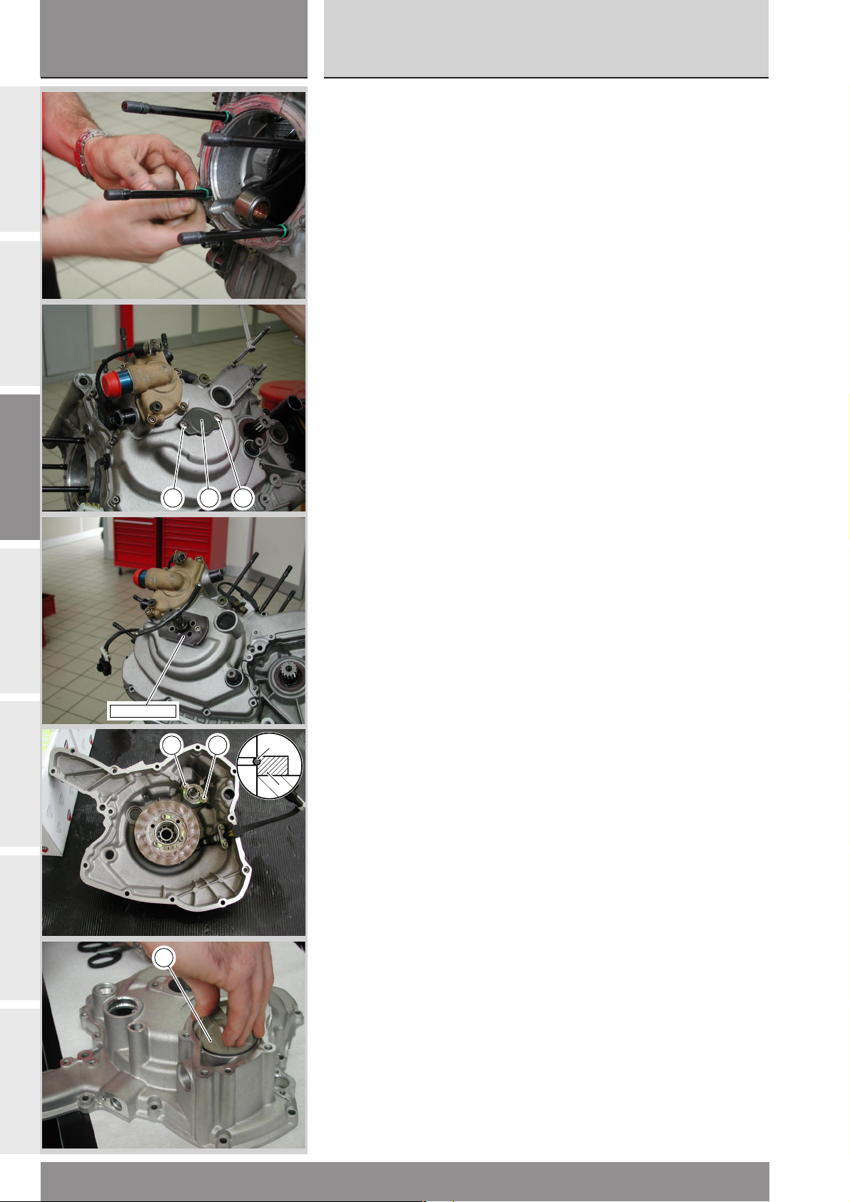
sezione / section
C
A
999RS04
Scomposizione motore
Engine disassembly
❍ Rimuovere gli OR dai prigionieri.
❍ Rimuovere la guarnizione base
cilindro.
❍
Remove OR-seals from stud bolts.
❍ Remove cylinder base gasket.
B
C
D
E
88713.1749
1 12
5 5
COPERCHIO ALTERNATORE
❍ Svitare le 2 viti (1) che fissano il
coperchietto (2) di chiusura del foro
in corrispondenza dell’albero
motore.
❍
Rimuovere il coperchietto (2).
❍
Svitare le viti di fissaggio del
coperchio alternatore. Vincolati a
questo coperchio si trovano lo
statore del generatore, i sensori
numero di giri e fase e il gruppo
pompa acqua.
❍
Fissare l’estrattore cod.
88713.1749 nei fori delle viti (1) di
fissaggio del coperchietto
precedentemente rimosso.
●
Ruotare lentamente il perno
centrale dell’attrezzo fino ad
ottenere il distacco del coperchio
dal semicarter alternatore.
Se si deve sostituire la tenuta
meccanica o i cuscinetti di supporto
della girante utilizzare la seguente
procedura:
●
Premere la girante mandando a
pacco la molla;
●
Mandare in battuta il distanziale (3)
4
3
in modo da poter sfilare l'anello
elastico di bloccaggio (4);
❍
Sfilare anche il distanziale (3);
❍
Svitare e rimuovere le due viti (5)
con rosetta per rimuovere il
cuscinetto sottostante;
❍
Sfilare la girante (6) con anello di
tenuta dal lato esterno.
ALTERNATOR COVER
❍ Unscrew the 2 bolts (1) fixing the
small cover (2) to the hole over the
crankshaft.
❍
Remove the cover (2).
❍ Unscrew the retaining screws
from the alternator cover. The
alternator cover houses the
generator stator, the rpm and timing
sensors and the coolant pump unit.
❍
Fix puller part no. 88713.1749 to
the screw holes (1) of the small
cover removed previously.
●
Slowly turn the center pin of the
puller to detach the cover from the
alternator cover.
To change the mechanical seal or
the rotor bearings, proceed as
follows:
●
Press the rotor so to fully
compress the spring;
●
Push the spacer (3) fully home
and remove the snap ring (4);
❍
Remove the spacer (3);
❍
Undo and remove the two screws
(5) with washers and then remove
bearing underneath.
❍
Take out the rotor (6) and seal
from the outside.
F
G
64
6
999RS - M.Y. 2004 - edizione/edition 01
Page 65
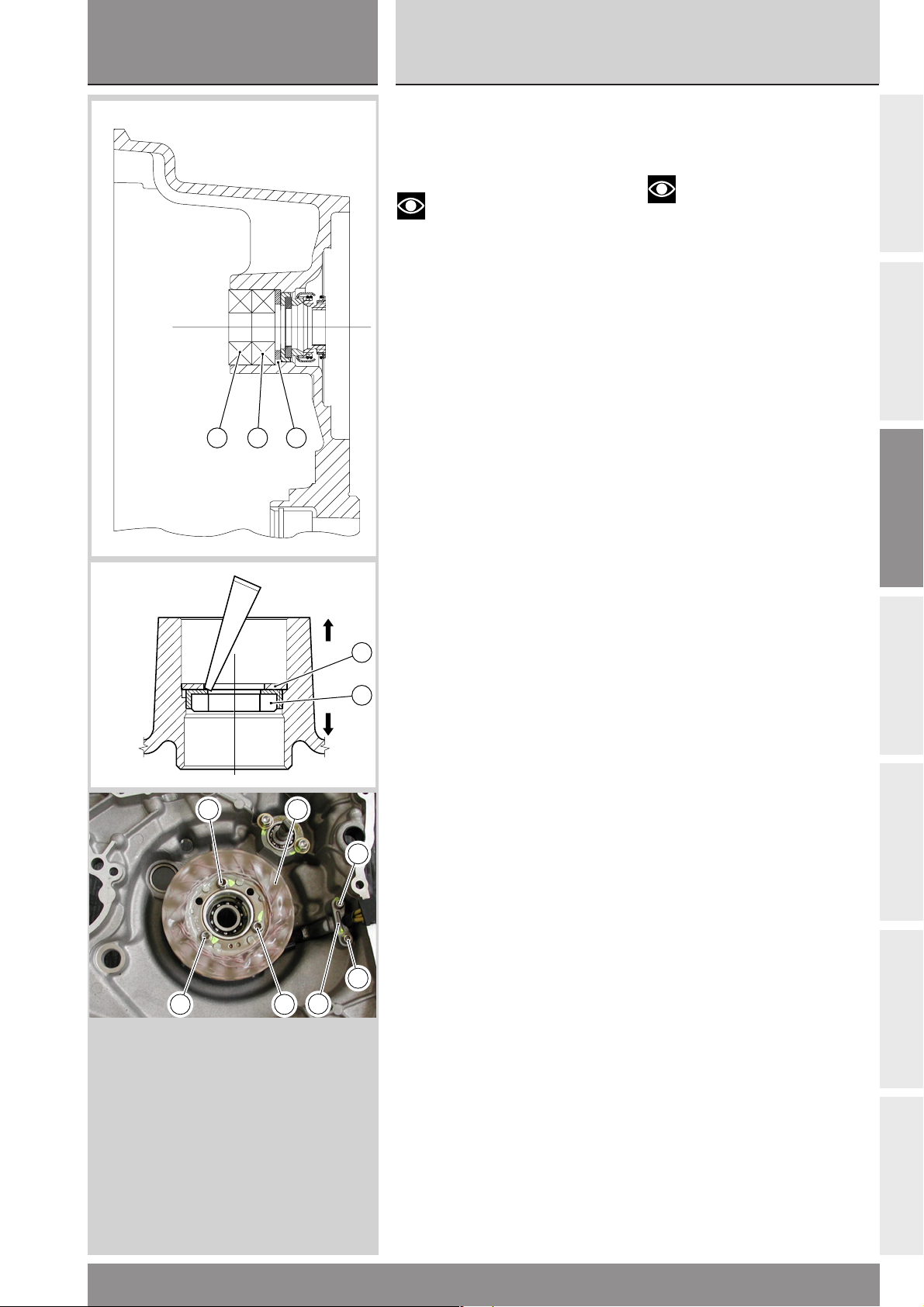
sezione / section
C
999RS04
Ricomposizione motore
Scomposizione motore
Engine reassembly
Engine disassembly
7 8 9
Operando dal lato girante con un
❍
punzone adatto, spingere sull’anello
interno del cuscinetto (7) di
estremità fino ad ottenerne
l’estrazione dal coperchio.
Note
Durante l’estrazione dei
cuscinetti cambiare continuamente
punto di appoggio del punzone in
modo da estrarre il cuscinetto in
squadro.
❍
Rimuovere allo stesso modo
l’altro cuscinetto (8).
❍
Sfilare il distanziale (9).
❍
Operando dal lato interno del
coperchio, rimuovere la
controfaccia (10) dell’anello di
tenuta.
❍ Rimuovere il distanziale interno (11).
❍ Se si vuole rimuovere lo statore
(12) del generatore dal suo fissaggio
all’interno del coperchio è
necessario rimuovere le viti (13) e la
piastrina (14) di fissaggio cavo
alternatore.
❍
Svitare le tre viti (15).
❍ Working with a suitable drift from
the rotor side, push the inner ring of
the bearing (7) until bearing is
removed from the cover.
Note
Change drift point of
application to remove bearings
squarely.
❍
Remove the other bearing (8).
❍ Slide out spacer (9).
❍
Working from cover inner side,
remove counter washer (10) from oil
seal.
❍
Remove inner spacer (11).
❍
If you wish to remove generator
stator (12) from inside the cover,
remove screws (13) and generator
cable holder plate (14) first.
❍
Loosen the three screws (15).
A
B
C
15
15 15
12
14
13
13
11
D
10
E
F
999RS - M.Y. 2004 - edizione/edition 01
G
65
Page 66
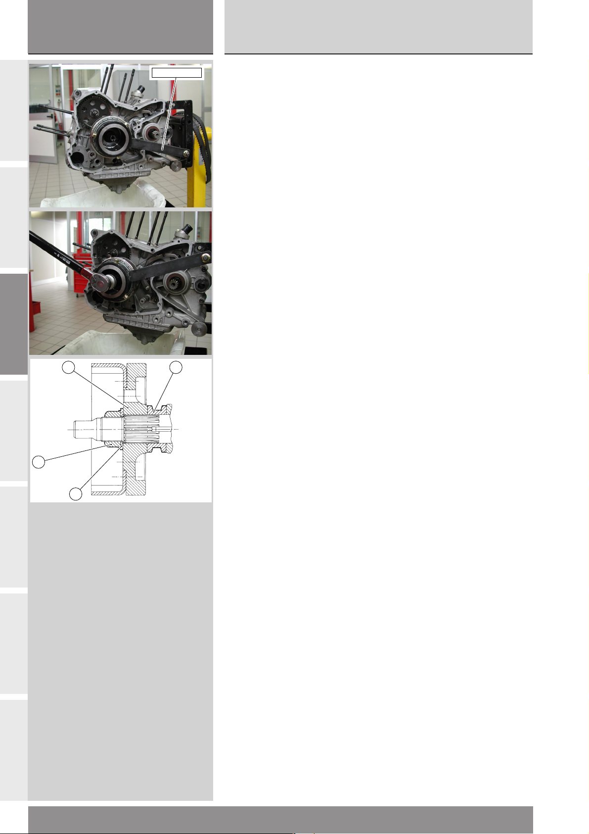
sezione / section
C
999RS04
Scomposizione motore
Engine disassembly
A
B
C
041.1.075.1A
ALTERNATORE E VOLANO
▲ Montare sul rotore del generatore
l’attrezzo cod. 041.1.075.1A e
bloccarne la rotazione portando
l’impugnatura a contatto con la parte
posteriore del carter.
❍
Svitare il dado di fissaggio del
rotore ruotandolo in senso
antiorario. Per poter eseguire
correttamente questa operazione è
necessario disporre di una chiave a
bussola con braccio
sufficientemente lungo, inoltre,
mentre si svita, spingere
assialmente la bussola per evitare
dannosi contraccolpi in caso di
fuoriuscita della bussola dal dado.
❍
Rimuovere il dado (1), la molla a
tazza (2), e il volano (3).
Nel caso la rimozione risulti
difficoltosa, adoperare un estrattore
commerciale (USAG 454/3).
❍
Sfilare il distanziale (4) volano.
ALTERNATOR AND FLYWHEEL
▲ Fit tool part no. 041.1.075.1A on
alternator rotor and bring tool handle
in contact with casing rear side to
prevent rotation.
❍
Unscrew the rotor retaining nut
counterclockwise. To unscrew the
nut, use a box spanner with a long
tommy bar. As you unscrew, press
axially down on the box spanner to
prevent the spanner from slipping
off the nut and damaging
components.
❍
Remove nut (1), Belleville washer
(2), and flywheel (3).
If removal proves difficult, use a
standard puller(USAG 454/3).
❍
Remove flywheel spacer (4).
D
E
F
3
1
2
4
G
66
999RS - M.Y. 2004 - edizione/edition 01
Page 67
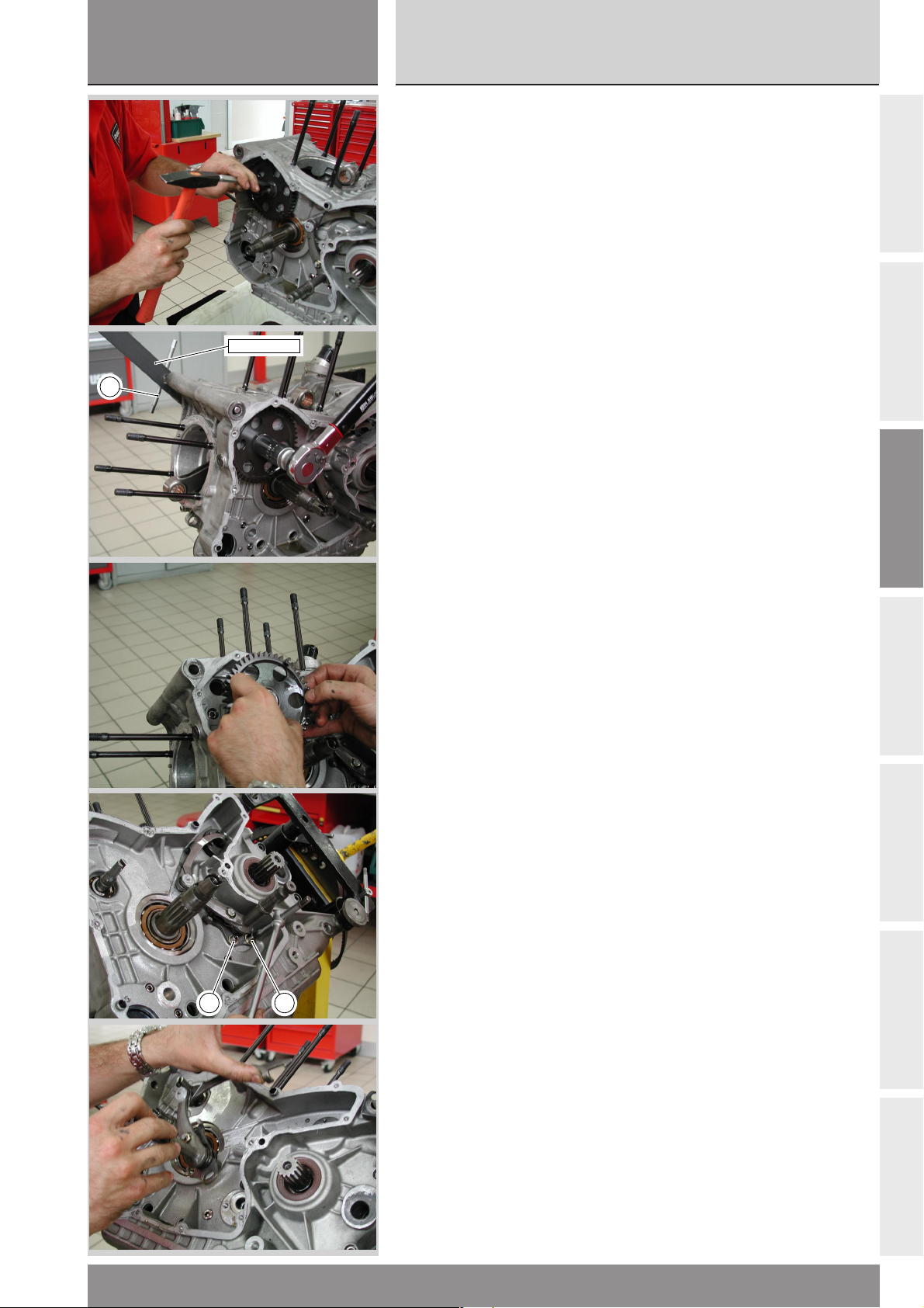
sezione / section
C
999RS04
Ricomposizione motore
Scomposizione motore
Engine reassembly
Engine disassembly
INGRANAGGI COMANDO
DISTRIBUZIONE
● Raddrizzare la rondella di sicurezza
del dado di bloccaggio ingranaggio
condotto distribuzione.
●
Montare nei 2 fori non filettati
della puleggia esterna sull’albero
rinvio distribuzione la chiave
cod. 88713.1805 e bloccarne la
rotazione inserendo un perno (1) nel
foro dell’impugnatura della chiave e
nella sede della vite di fissaggio
anteriore blocco motore al telaio.
❍
Svitare il dado di fissaggio
88713.1805
1
ingranaggio condotto ruotandolo in
senso antiorario con una chiave
adatta.
❍
Rimuovere il dado, la rondella,
l’ingranaggio condotto della
distribuzione e la linguetta.
❍
Sfilare dall’albero motore
l’ingranaggio di comando
distribuzione e la relativa linguetta.
TIMING GEARS
● Straighten the safety washer of
the timing driven gear locking nut.
●
Fit the service tool part no.
88713.1805 to the two unthreaded
holes in the outer roller of timing
layshaft. Insert a pin (1) through the
hole of the tool handle and into the
front engine-to-frame mounting bolt
hole to clamp the roller in position.
❍
To unscrew the retaining nut of
the driven gear, turn it
counterclockwise with a suitable
tool.
❍
Remove nut, washer, driven gear
and key.
❍
Remove timing drive gear and its
key from crankshaft.
A
B
C
1 1
LEVERAGGIO SELEZIONE
MARCE
❍ Svitare le 2 viti (1) di fissaggio del
leveraggio di selezione del cambio.
❍ Rimuovere il leveraggio completo
dal carter.
GEAR SELECTOR LEVER
❍ Unscrew the 2 retaining bolts (1)
from the gear selector lever.
❍ Remove the complete lever
assembly from casing.
D
E
F
999RS - M.Y. 2004 - edizione/edition 01
G
67
Page 68
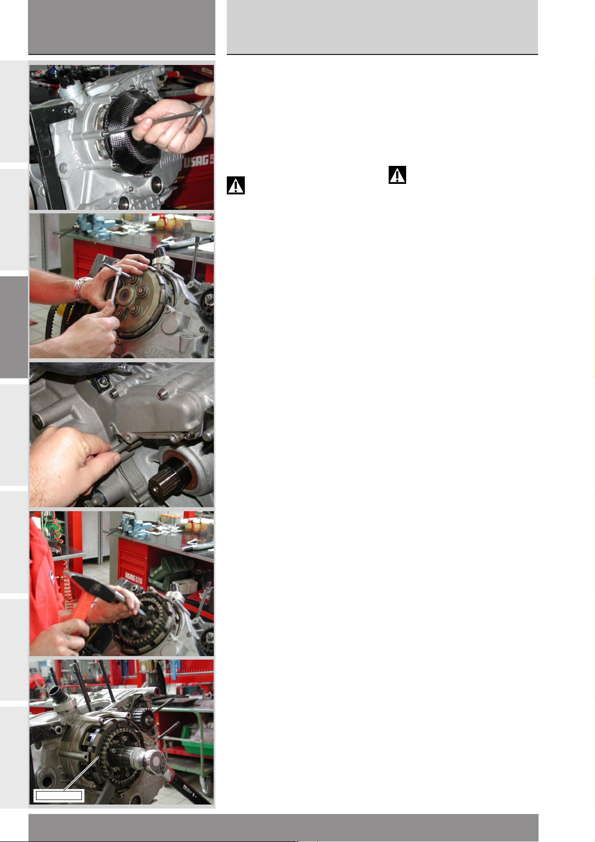
sezione / section
C
999RS04
Scomposizione motore
Engine disassembly
A
B
C
FRIZIONE
❍ Svitare le 3 viti di fissaggio del
coperchio di protezione frizione e
rimuoverlo.
❍ Svitare e rimuovere le quattro viti
di fissaggio del pacco frizione e
sfilare le molle.
❍ Sfilare lo spingidisco e i dischi
della frizione.
Attenzione
Sfilare l’asta di comando
frizione dal lato alternatore,
altrimenti si rischia di rovinare il
labbro del paraolio inserito
nell’albero del cambio.
● Raddrizzare la rosetta di sicurezza
del dado di bloccaggio tamburo
frizione.
▲
Montare sul tamburo l’attrezzo
cod. 88713.0146 e bloccarne la
rotazione portando l’impugnatura
dell’attrezzo a contatto con un perno
inserito in uno dei fori di fissaggio
blocco motore al telaio.
CLUTCH
❍ Loosen the 3 clutch cover screws
and remove cover.
❍ Unscrew and remove the 4
retaining screws of the clutch plate
set and remove the springs.
❍ Slide out plate pusher and clutch
plates.
Warning
Slide out clutch pushrod from
the generator side in order not to
damage the oil seal lip on gearbox
shaft.
● Straighten safety washer of the
clutch drum nut.
▲
Fit tool part no. 88713.0146 on
clutch drum and lock it by making
the tool handle contact a pin
inserted in one of the holes fixing
engine block to frame.
D
E
F
G
88713.0146
68
999RS - M.Y. 2004 - edizione/edition 01
Page 69
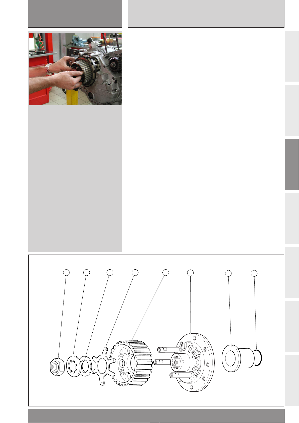
sezione / section
C
999RS04
Ricomposizione motore
Scomposizione motore
Engine reassembly
Engine disassembly
❍ Con una chiave a bussola adatta
svitare il dado di bloccaggio
tamburo frizione.
Rimuovere:
- il dado (1);
- la rondella (tenera) (2);
- il distanziale (3);
- la molla antisaltellamento (4);
- il tamburo frizione (5);
- il gruppo flangia (6);
- il distanziale (7) con OR (8).
❍ Using a suitable socket wrench,
unscrew the clutch drum lock nut.
Remove
- nut (1);
- (soft) washer (2);
- spacer (3);
- anti-slip spring (4);
- clutch drum (5);
- flange assembly (6);
- spacer (7) with OR seal (8).
A
B
C
1 2 3 4 5
D
6
7 8
E
F
999RS - M.Y. 2004 - edizione/edition 01
G
69
Page 70
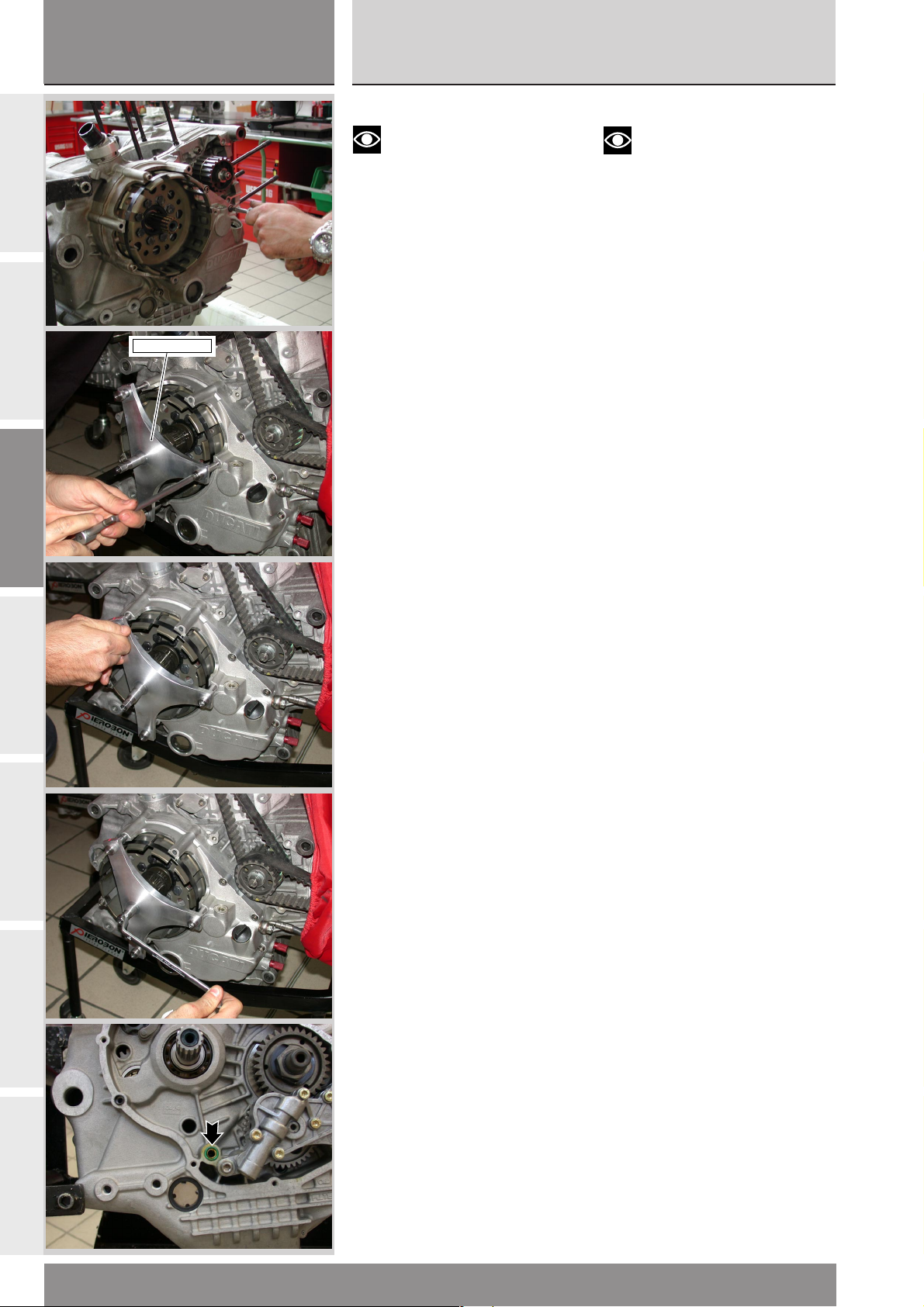
sezione / section
C
999RS04
Scomposizione motore
Engine disassembly
A
B
C
D
041.1.032.2A
COPERCHIO FRIZIONE
Note
Se non deve essere eseguito
nessun intervento sugli elementi che
compongono il coperchio frizione,
evitare di rimuovere la campana e
l’ingranaggio della primaria dal
coperchio.
❍
Svitare e rimuovere le 8 viti di
fissaggio del coperchio frizione e,
aiutandosi con un martello di
plastica, battere in vari punti sul
contorno del coperchio per favorirne
il distacco dal semicarter.
❍
Per rimuovere il coperchio
frizione adoperare l’attrezzo
cod. 041.1.032.2A.
● Avvitare le due viti corte
dell’attrezzo sul coperchio frizione,
nelle sede per le viti di supporto del
coperchio.
● Avvitare la terza vite, quella più
lunga, di qualche filetto, evitando di
portarla in battuta.
●
Ruotare la vite centrale
dell’attrezzo fino al distacco del
coperchio frizione dal carter centrale
e svitare completamente la vite
lunga dell’attrezzo.
❍
Rimuovere l’anello OR in
corrispondenza del passaggio olio
tra coperchio frizione e semicarter.
❍
Sfilare dall’albero primario il
distanziale.
CLUTCH COVER
Note
If clutch cover parts do not
have to be serviced, do not remove
clutch housing and primary drive
gear from clutch cover.
❍ Undo and remove the 8 retaining
screws from the clutch cover and tap
at different positions around cover
with a plastic mallet to separate
cover from casing.
❍
To remove clutch cover, use tool
part no. 041.1.032.2A.
●
Screw the two short screws of the
tool into the holes of the clutch
cover mount.
● Screw the third longer screw. Do
not tighten it.
●
Turn tool central screw until clutch
cover separates from central casing.
Then fully loosen tool longer screw.
❍
Remove OR-seal at the oil duct
between clutch cover and casing.
❍
Remove spacer from gearbox
primary shaft.
E
F
G
70
999RS - M.Y. 2004 - edizione/edition 01
Page 71
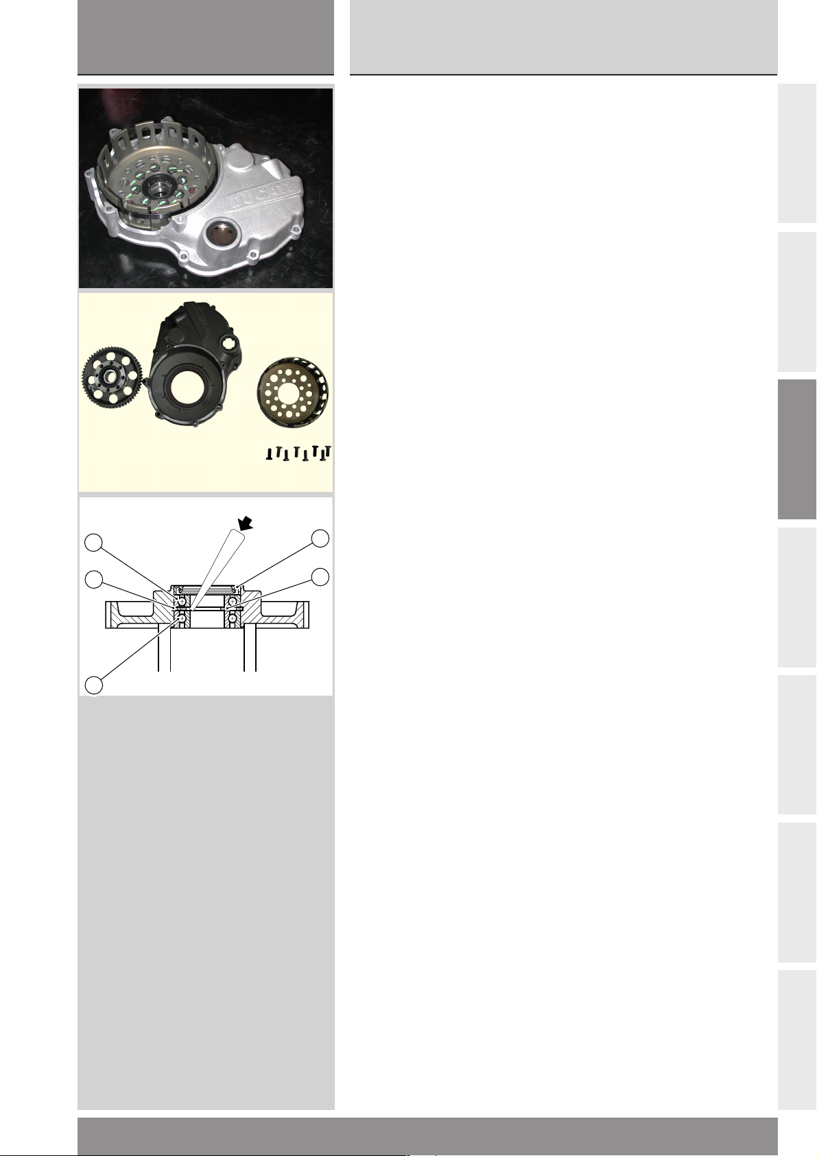
sezione / section
C
999RS04
Ricomposizione motore
Scomposizione motore
Engine reassembly
Engine disassembly
INGRANAGGIO CONDOTTO
DELLA TRASMISSIONE
PRIMARIA E CAMPANA
FRIZIONE
❍ Svitare e rimuovere le 8 viti che
bloccano la campana frizione
all’ingranaggio primario.
❍
Rimuovere la campana frizione.
❍ Rimuovere l’ingranaggio condotto
della trasmissione primaria.
Per la sostituzione degli elementi
interni all’ingranaggio operare come
segue:
❍
Rimuovere il paraolio (1)
dall’ingranaggio.
❍
Con un piccolo punzone scostare
il distanziale (2) interno ai due
cuscinetti.
❍
Con un punzone adatto,
appoggiato all’anello interno del
cuscinetto (3), spingere
quest’ultimo verso l’esterno
cambiando continuamente punto di
appoggio per ottenere un’estrazione
in squadro del cuscinetto.
❍
Rimuovere il distanziale interno (2)
e l’anello seeger speciale (4) (questi
elementi vanno sempre sostituiti in
coppia).
1
❍
5
4
2
Rimuovere l’altro cuscinetto (5)
utilizzando un tampone adatto che
appoggi sull’anello esterno.
CLUTCH HOUSING AND
PRIMARY DRIVEN GEAR
❍ Loosen and remove the 8 screws
fixing clutch housing to primary
driven gear.
❍
Remove cluctch housing.
❍ Remove primary driven gear.
To change gear inner parts, proceed
as follows:
❍
Remove the oil seal (1) from the
gear.
❍
Using a small drift, move aside
the spacer (2) positioned between
the two bearings.
❍
Using a suitable drift on the inner
ring of the bearing (3) push the
bearing outwards; change the drift
position frequently so that the
bearing is pushed out squarely.
❍
Remove the inner spacer (2) and
the special snap ring (4) (always
change these two components as a
pair).
❍
Using a suitable drift on the outer
ring, remove the other bearing (5).
A
B
C
D
3
E
F
999RS - M.Y. 2004 - edizione/edition 01
G
71
Page 72
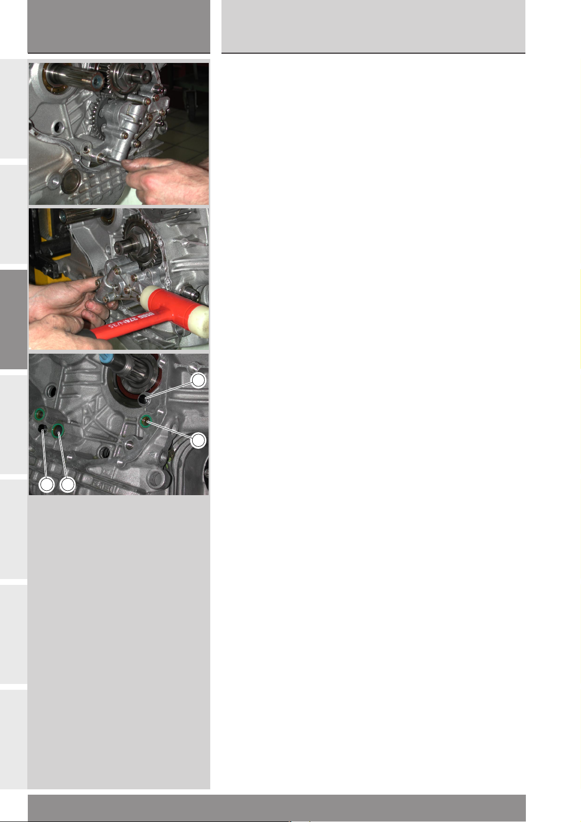
sezione / section
C
999RS04
Scomposizione motore
Engine disassembly
A
B
C
POMPA OLIO
❍ Svitare e rimuovere le viti di
fissaggio della pompa olio
completa.
❍
Rimuovere la pompa olio,
eventualmente aiutandosi con un
martello di plastica e sfilare dal
semicarter i due anelli OR (1) e le 2
boccole di centraggio (2).
OIL PUMP
❍ Undo and remove the oil pump
retaining bolts.
❍
Remove oil pump. If necessary,
use a plastic mallet to remove the
OR-seals (1) and the two centering
bushes (2) from casings.
D
E
F
2
1
2 1
G
72
999RS - M.Y. 2004 - edizione/edition 01
Page 73
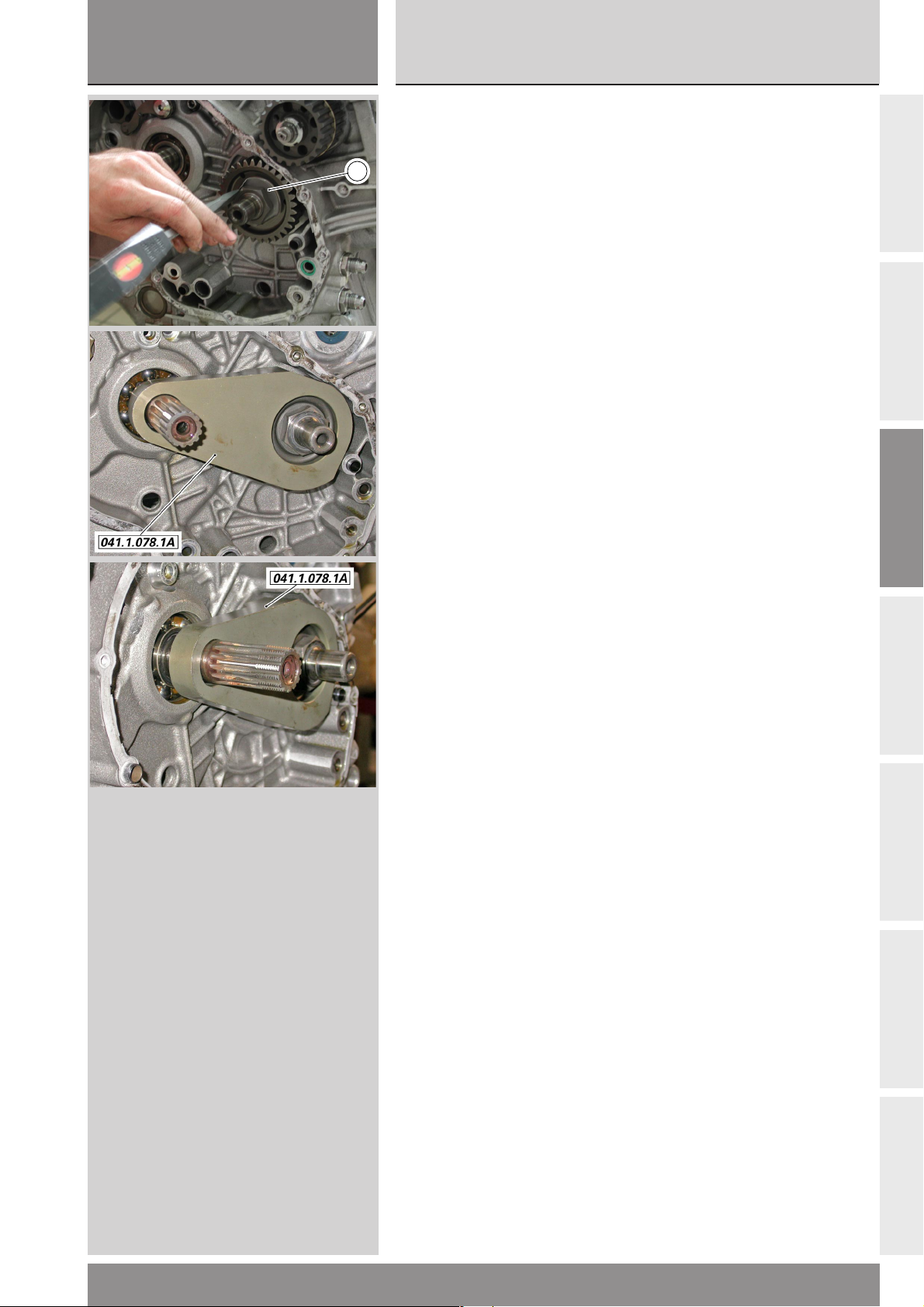
sezione / section
C
999RS04
Ricomposizione motore
Scomposizione motore
Engine reassembly
Engine disassembly
INGRANAGGIO ALBERO
MOTORE DELLA
TRASMISSIONE PRIMARIA
● Raddrizzare la rosetta (1) di
1
sicurezza del dado di bloccaggio
ingranaggio sollevando la parte
ribadita sull'ingranaggio stesso ed
abbassando la parte ribadita sul
dado.
▲
Montare sull’ingranaggio l’attrezzo
cod. 041.1.078.1A e bloccarne la
rotazione inserendo il mozzetto
sull’albero primario.
❍
Utilizzando una chiave a bussola
con braccio sufficientemente lungo
allentare il dado di fissaggio
ingranaggio primario.
❍ Rimuovere il dado, la rosetta di
sicurezza e l’ingranaggio ed il
distanziale dietro di esso.
CRANKSHAFT PRIMARY
DRIVE GEAR
● Straighten the primary drive gear
retaining nut safety washer (1). Lift
the bent end on the gear and press
down the bent end over the nut.
▲
Fit tool part no. 041.1.078.1A on
gear and prevent rotation inserting
the hub onto the primary shaft.
❍
Using a socket spanner with
suitably long handle, loosen the
primary drive gear retaining nut.
❍ Remove nut, safety washer, gear
and spacer.
A
B
C
D
E
F
999RS - M.Y. 2004 - edizione/edition 01
G
73
Page 74
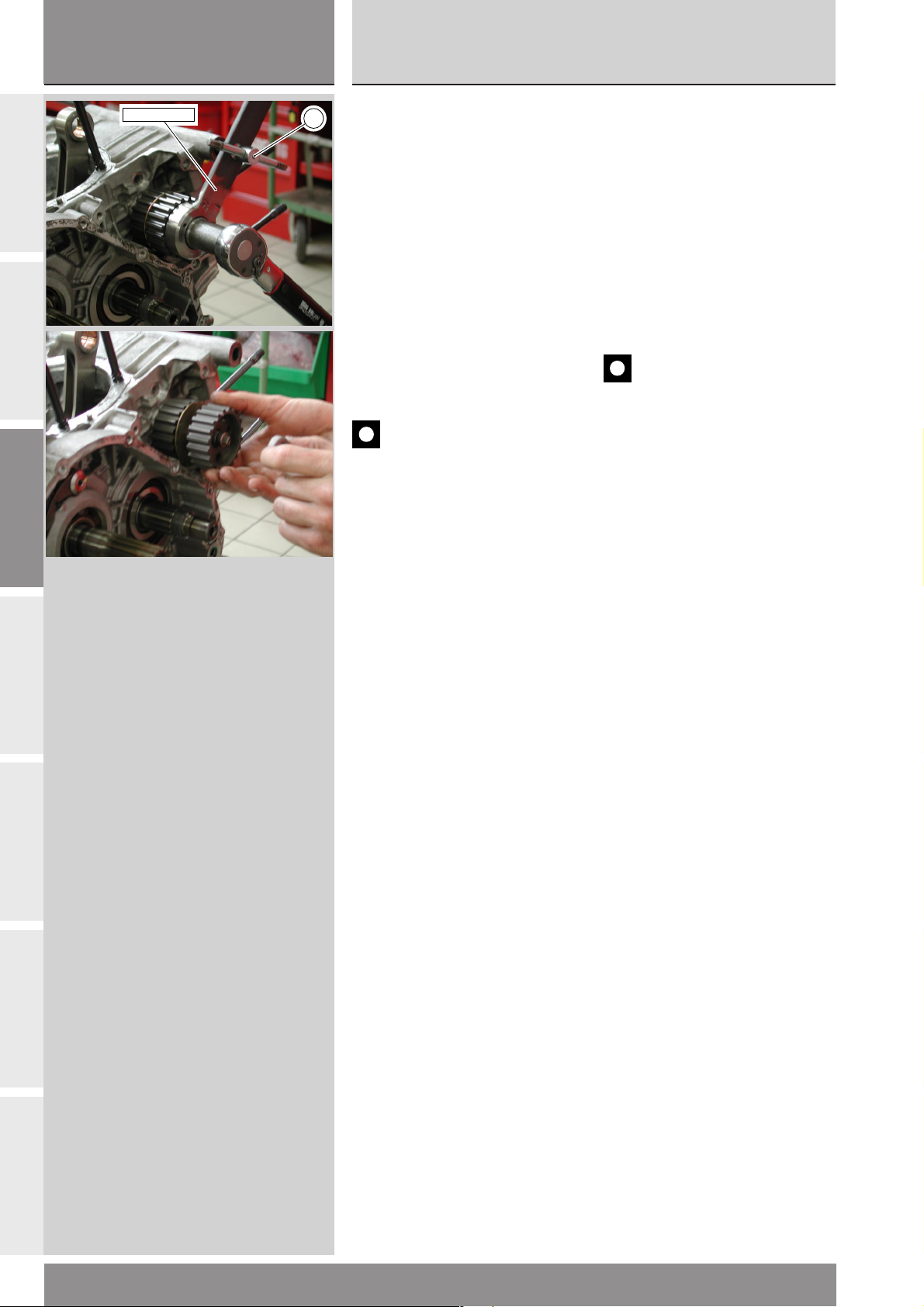
sezione / section
C
999RS04
Scomposizione motore
Engine disassembly
A
B
C
88713.1805
PULEGGE RINVIO
DISTRIBUZIONE
A
● Montare nei due fori non filettati
della puleggia esterna la chiave cod.
88713.1805 e bloccarne la rotazione
inserendo un perno (A) nel foro
dell’impugnatura dell’attrezzo e
nella sede della vite di fissaggio
anteriore blocco motore al telaio.
❍
Utilizzando la bussola dell’attrezzo
inserita in una chiave a cricchetto
allentare la ghiera di fissaggio
pulegge distribuzione.
❍
Sfilare la ghiera, la rosetta, la
puleggia esterna, la prima linguetta,
la rondella di guida, la puleggia
interna, la seconda linguetta e il
distanziale interno.
Importante
In fase di rimontaggio,
utilizzare una ghiera e una rosetta
nuove.
Se l’operazione di rimozione delle
pulegge risulta difficoltosa, utilizzare
l’estrattore cod. 88713.1749,
precedentemente utilizzato per la
rimozione del coperchio alternatore,
applicato nei due fori filettati della
puleggia da rimuovere.
TIMING BELT ROLLERS
● Fit service tool part no.
88713.1805 to the two unthreaded
holes of the outer roller. Clamp the
roller in position by inserting a pin
(A) into the hole of the tool handle
and into the front engine-to-frame
mounting hole.
❍
Fit service tool socket into a
ratchet wrench, and loosen the
timing roller ring nut.
❍
Remove ring nut, washer, outer
roller, first key, guide washer, inner
roller, second key and inner spacer.
Caution
At reassembly, fit a new ring
nut and a new washer.
If rollers prove difficult to remove,
use puller part no. 88713.1749
previously used to remove alternator
cover. Insert tool into the two
threaded holes of the roller to be
removed.
D
E
F
G
74
999RS - M.Y. 2004 - edizione/edition 01
Page 75
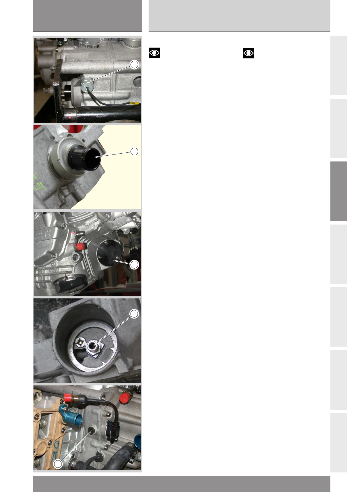
sezione / section
C
999RS04
Ricomposizione motore
Scomposizione motore
Engine reassembly
Engine disassembly
ACCESSORI BASAMENTO
Note
La rimozione degli elementi di
seguito illustrata è finalizzata alla
1
sostituzione e/o alla completa
pulizia dei semicarter. In caso di
riutilizzo dei semicarter la loro
rimozione non è indispensabile.
❍ Svitare e rimuovere il sensore
posizione cambio (1) dal retro del
carter.
❍
Rimuovere il raccordo (2) di sfiato
vapori olio dal basamento. Per
eseguire questa operazione è
necessario munirsi di una chiave a
settore con dentino cilindrico (tipo
USAG 282/45-50).
2
❍ Svitare e rimuovere il nipplo (3) di
supporto filtro olio.
❍ Svitare e rimuovere il tappo (4),
con relativa guarnizione, per
controllo traferro sensore di fase
motore.
❍
Rimuovere il coperchio (5) di
chiusura sede motorino avviamento
svitando le 3 viti di fissaggio.
CRANKCASE FITTINGS
Note
Remove the parts described in
this paragraph if casings need
replacing and/or complete
cleaning. Do not remove them if
casings are to be used again.
❍ Undo and remove gearbox
position sensor (1) from behind the
casing.
❍ Remove the oil breather
connector (2) from the crankcase.
To remove this part use a spanner
with round pins (e.g. USAG 282/45-
50).
❍ Unscrew and remove oil filter
nipple (3).
❍ Unscrew and remove plug (4) with
seal in order to check the engine air
gap of sensors.
❍ Unscrew the 3 retaining screws
and remove the cover (5) from the
starter motor housing.
A
B
C
D
5
3
E
F
4
999RS - M.Y. 2004 - edizione/edition 01
G
75
Page 76
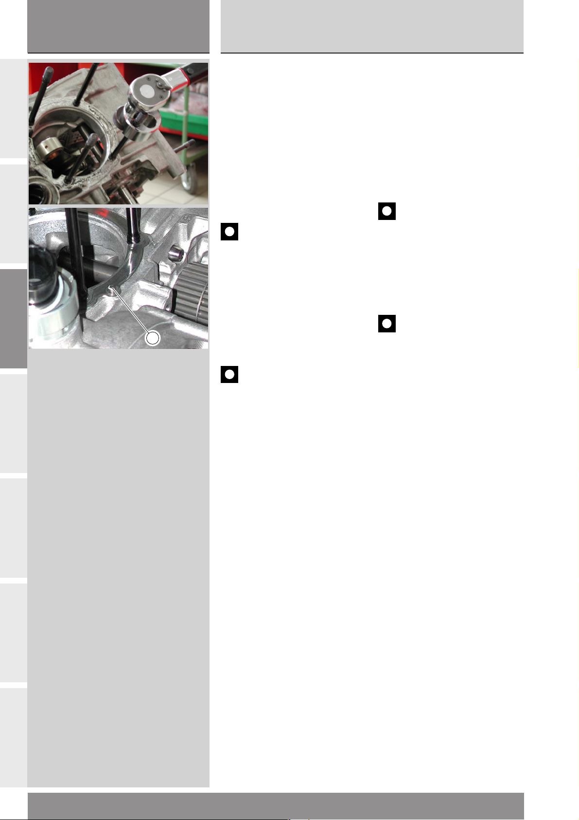
sezione / section
C
999RS04
Scomposizione motore
Engine disassembly
A
B
C
PRIGIONIERI, BOCCOLE E
GRANI DI CENTRAGGIO
Verificare che le aperture del carter
siano tappate con uno straccio
quindi procedere alla rimozione dei
prigionieri. Per eseguire
correttamente questa operazione è
necessario disporre di un attrezzo
che non segni eccessivamente il
prigioniero (del tipo con ganasce a
rulli). Applicare l’attrezzo in modo
che la presa avvenga alla fine della
filettatura del prigioniero, nella parte
cilindrica di diametro maggiore.
Importante
Sostituire i prigionieri che
risultano eccessivamente segnati o
rovinati dopo questa operazione.
Se l’operazione di rimozione dagli
alloggiamenti sul carter delle
boccole di centraggio dei coperchi
alternatore, del coperchio frizione e
della pompa olio risulta difficoltosa è
1
consigliabile utilizzare un maschio
sinistro n° 4 con il quale forzare in
uscita le boccole.
Importante
Sostituire sempre le boccole
rimosse.
STUD BOLTS, CENTERING
BUSHES AND LOCATORS
Before removing the stud bolts,
make sure that all the openings in
the crankcase have been blocked off
with rags. To remove stud bolts, use
a tool which will not excessively
mark the stud bolts (e.g. a tool with
roller jaws). Grip the stud bolts with
the tool at the end of the threading
on the cylindrical section with the
largest diameter.
Caution
Change all stud bolts which
are badly marked or damaged.
If the centring bushes (of the
alternator, clutch and oil pump
covers) prove difficult to remove
from the crankcase, use a left-hand
n° 4 screw tap to force the bushes
out.
Caution
At reassembly, always fit new
bushes.
To remove the cylinder centering
locators (1), use pliers.
At re-assembly, fit new locators.
D
E
F
Per quanto riguarda i grani di
centraggio (1) dei cilindri è possibile
rimuoverli utilizzando un paio di
pinze. Anche questi è consigliabile
sostituirli, una volta rimossi.
G
76
999RS - M.Y. 2004 - edizione/edition 01
Page 77
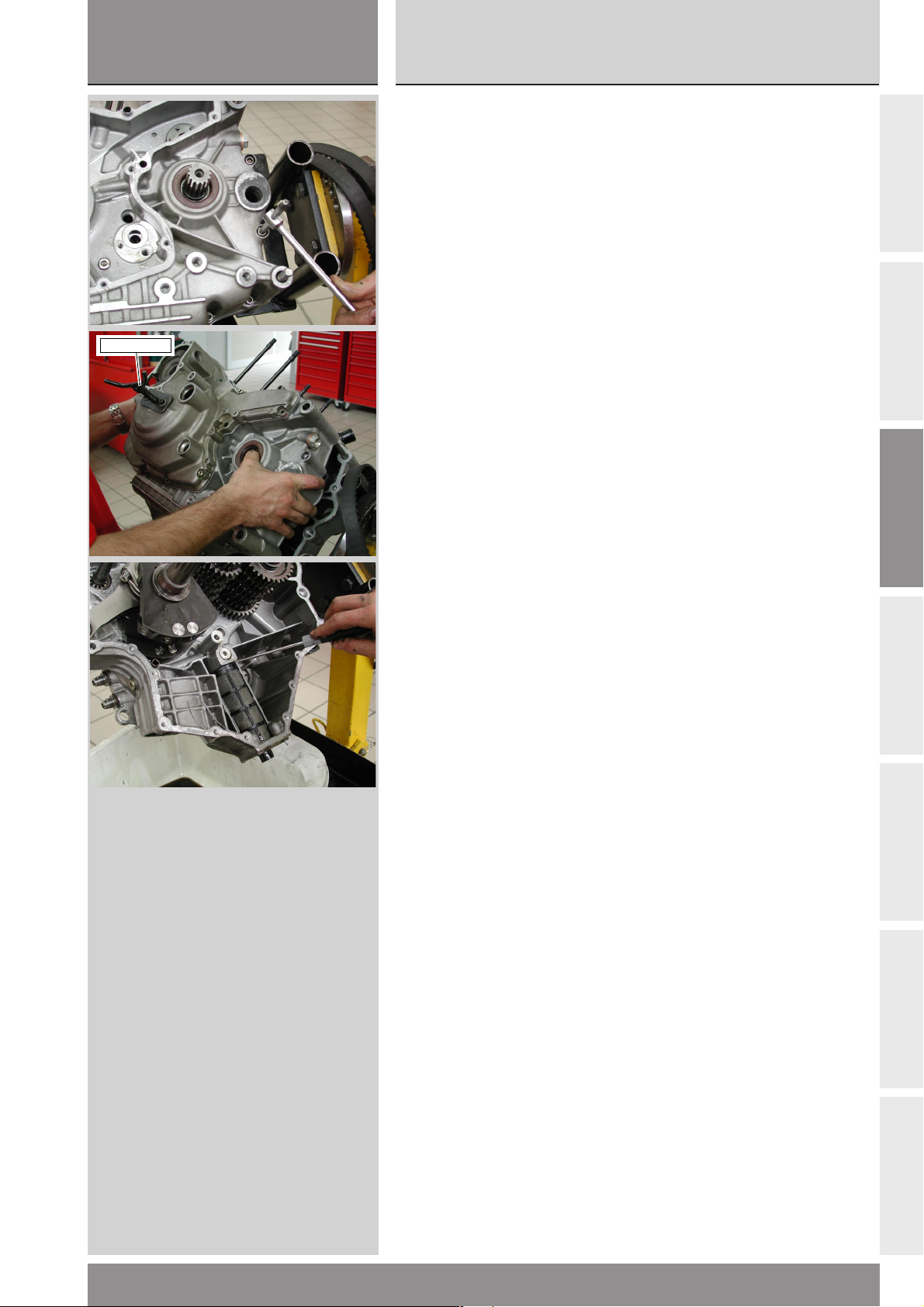
sezione / section
C
999RS04
Ricomposizione motore
Scomposizione motore
Engine reassembly
Engine disassembly
88713.1749
APERTURA CARTER
❍ Svitare per prime le due viti,
M8x90, poste sul semicarter
frizione, in corrispondenza della
sede del cilindro verticale.
❍
Capovolgere il carter e svitare le
rimanenti viti di fissaggio dei due
semicarter.
●
Riutilizzare il coperchio alternatore
(o un coperchio di servizio come in
foto) con l’estrattore cod.
88713.1749 montato; fissarlo al
semicarter con tre viti originali
diametralmente opposte.
❍
Azionare il perno centrale
dell’attrezzo e
contemporaneamente battere con
un martello in plastica sull’albero
secondario del cambio fino ad
ottenere la separazione dei
semicarter.
❍
Rimuovere il semicarter
alternatore prestando attenzione ai
rasamenti installati in
corrispondenza degli alberi cambio,
motore e tamburo selettore.
❍
Rimuovere dall’estremità
dell’albero primario l’anello interno
e introdurlo nel relativo cuscinetto
sul semicarter alternatore.
❍
Rimuovere il filtro a rete, facendo
leva con un cacciavite.
OPENING THE CRANKCASE
❍ Unscrew the first two M8x90
screws on the clutch-side casing at
the vertical cylinder location.
❍
Overturn the crankcase and
unscrew the other screws on
casings.
●
Re-use alternator cover (or a
service cover as shown in the
picture) with puller part no.
88713.1749 fitted. Secure it to the
casing using three original opposite
screws.
❍
Turn the puller center pin and at
the same time tap the gearbox
secondary shaft with a plastic
hammer until the two casings
separate.
❍
Remove the alternator-side
casing. Take care not to lose the
shims on the gearbox shaft, the
crankshaft and the selector drum
shaft.
❍
Remove the inner ring from the
primary shaft and insert it in the
corresponding bearing in the
alternator-side casing.
❍
Lever with a screwdriver to
remove mesh filter.
A
B
C
D
E
F
999RS - M.Y. 2004 - edizione/edition 01
G
77
Page 78
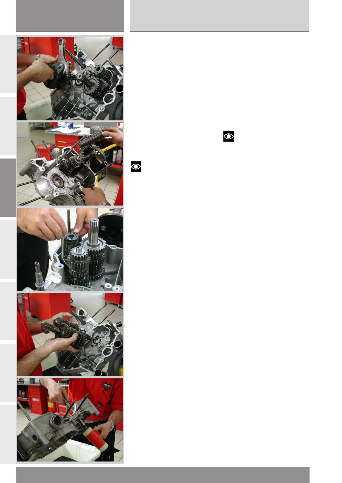
sezione / section
C
999RS04
Scomposizione motore
Engine disassembly
A
B
C
ELEMENTI INTERNI
SEMICARTER
❍ Sfilare l’albero motore dal
semicarter e recuperare il rasamento
interno.
❍
Sfilare gli alberi di guida delle
forcelle.
❍
Spostare le forchette in modo da
disimpegnarle dalle cave del
tamburo selettore ed estrarre il
tamburo recuperando il relativo
rasamento.
❍
Rimuovere le forcelle di innesto
delle marce facendo attenzione alle
boccole inserite nei perni di guida.
❍
Rimuovere gli alberi primario e
secondario del cambio completi di
ingranaggi e recuperare i relativi
rasamenti.
Note
Per comodità di rimontaggio si
consiglia di lasciare l’anello interno
del cuscinetto di estremità
sull’albero secondario montato su
quest’ultimo.
CASINGS INNER PARTS
❍ Remove the crankshaft from the
casing. Keep the inner shim.
❍
Slide out the fork guide rods.
❍ Move the forks so that they
disengage from the grooves in the
selector drum. Remove the drum
and keep the shim.
❍
Remove the gear selector forks
taking care not to lose the bushes in
the guide pins.
❍
Remove the gearbox primary and
secondary shafts complete with
gears and keep the shims.
Note
To facilitate reassembly, leave
the inner ring of the end bearing on
the secondary shaft.
❍
Working on the outer side of the
clutch-side casing, remove the
circlip from the timing layshaft.
❍
Working from the inside of the
casing, remove the timing layshaft.
D
E
❍
Rimuovere l’anello elastico
sull’albero rinvio distribuzione, nella
parte esterna al semicarter frizione.
❍
Sfilare l’albero rinvio distribuzione
dal lato interno del semicarter.
F
G
78
999RS - M.Y. 2004 - edizione/edition 01
Page 79
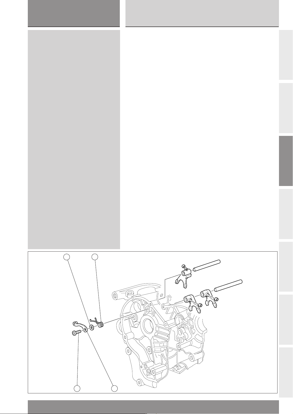
sezione / section
2
1
3
4
C
999RS04
Ricomposizione motore
Scomposizione motore
Engine reassembly
Engine disassembly
❍ Rimuovere la levetta ferma
marce (1) svitando la vite (2) di
fissaggio al semicarter. Recuperare
il rasamento (3) e la molla (4).
❍ To remove the gear stop lever (1),
unscrew the fixing bolt (2) from
casing. Remove shim (3) and spring
(4).
A
B
C
D
E
F
999RS - M.Y. 2004 - edizione/edition 01
G
79
Page 80
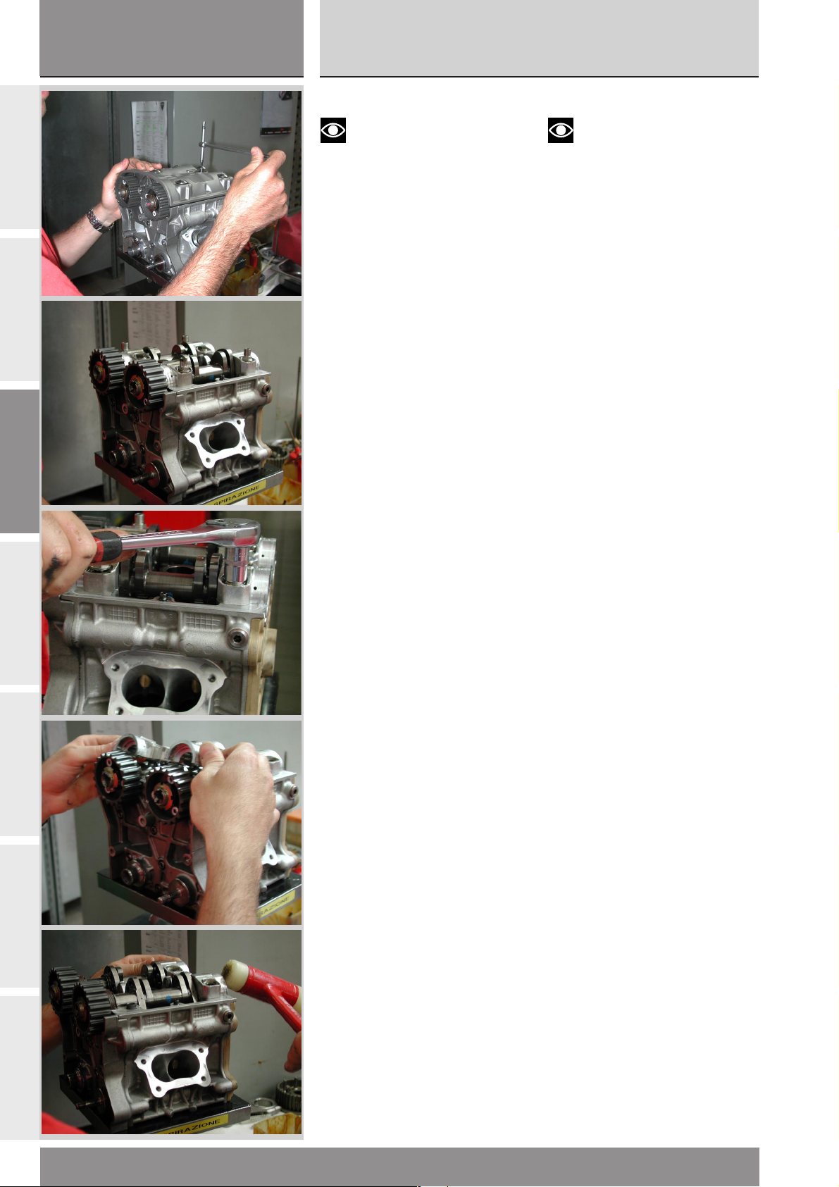
sezione / section
C
999RS04
Scomposizione motore
Engine disassembly
A
B
C
SCOMPOSIZIONE TESTE
Note
La procedura di smontaggio
qui riportata è riferita ad una testa
verticale; per la testa orizzontale
procedere in modo analogo sebbene
cambino alcuni componenti come
coperchi testa, tipo e numero di viti
dei cappellotti.
❍
Svitare e rimuovere le viti di
fissaggio testa, rimuovere il
coperchio testa e la guarnizione.
❍
Svitare le viti e le colonnette
fissaggio cappellotti camme.
❍
Rimuovere i cappellotti camme
aiutandosi eventualmente con dei
leggeri colpi di martello con battenti
in plastica.
HEADS DISASSEMBLY
Note
The disassembly procedure
contained in this paragraph refers to
a vertical head; repeat it on the
horizontal head even if some parts,
such as head covers, the type and
number of bolts of head caps, may
vary.
❍
Undo and remove head bolts,
remove head cover and gasket.
❍
Undo camshaft cover screws and
stud bolts.
❍
Remove camshaft covers. Use a
plastic mallet, if necessary.
D
E
F
G
80
999RS - M.Y. 2004 - edizione/edition 01
Page 81
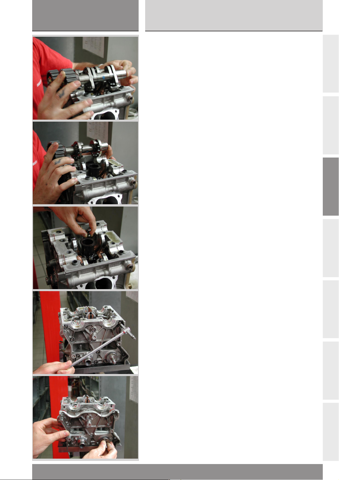
sezione / section
C
999RS04
Ricomposizione motore
Scomposizione motore
Engine reassembly
Engine disassembly
Rimuovere gli alberi a camme.
❍
❍ Rimuovere i registri di apertura,
avendo cura di riporre i registri di
apertura, quelli di chiusura e le
valvole in modo da non mescolarli.
Ciò risulterà utile per richiudere il
motore eventualmente si dovessero
riutilizzare gli stessi registri.
❍
Rimuovere le viti di fissaggio
cartelle lato cinghia.
❍
Rimuovere la cartella lato cinghia.
❍ Remove camshafts.
❍ Remove opening shims. Take
care not to make confusion between
opening and closing shims and
valves. This proves useful in case
the same shims are used to close
engine.
❍
Remove belt-side cover fixing
screws.
❍
Remove belt-side cover.
A
B
C
D
E
F
999RS - M.Y. 2004 - edizione/edition 01
G
81
Page 82
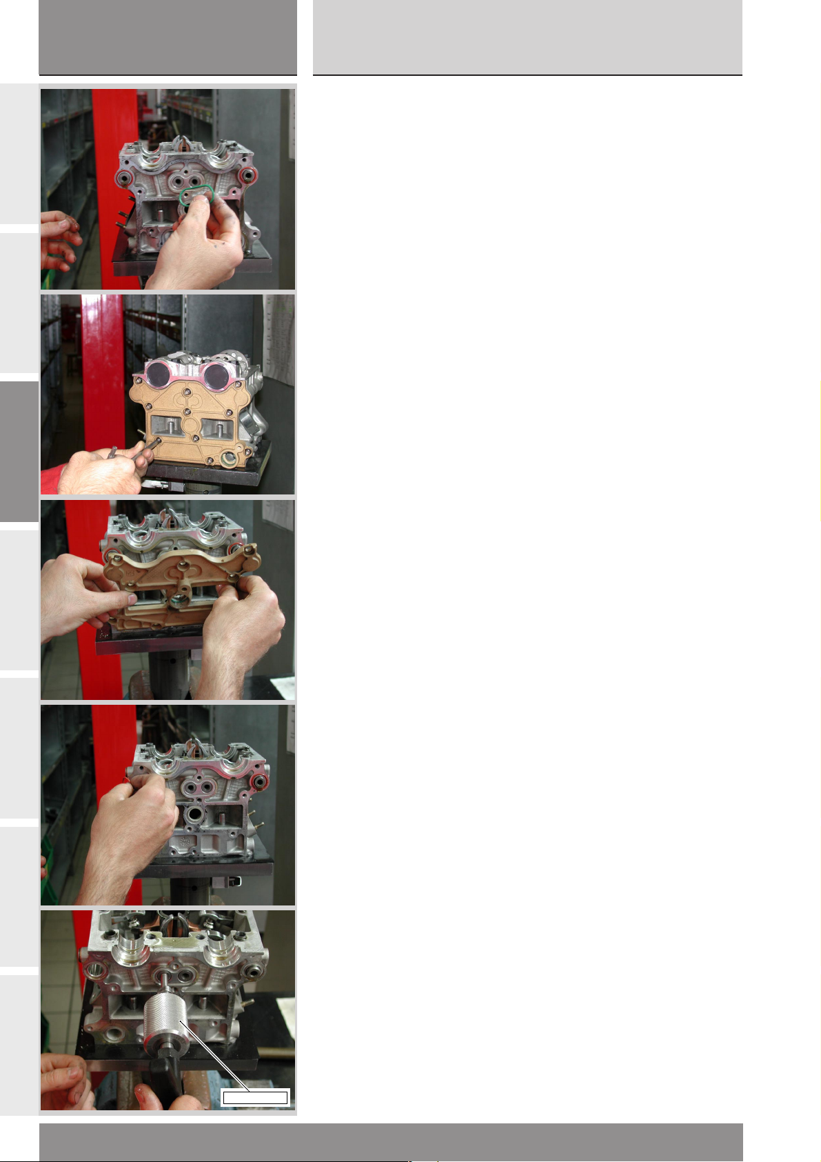
sezione / section
C
999RS04
Scomposizione motore
Engine disassembly
A
B
C
●
Recuperare i tre OR (uno color
verde e due rossi) posti tra testa e
cartella.
❍
Svitare le viti di fissaggio della
cartella lato raccordo acqua.
❍
Rimuovere la cartella lato raccordo
acqua.
●
Preoccuparsi di recuperare gli OR
(uno color verde e due rossi).
❍
Per rimuovere i perni bilanciere
usare l’attrezzo cod. 88713.1994;
avvitare il perno filettato
dell’attrezzo all’interno del perno
bilanciere e, con un movimento
rapido, tirare il battente dell’attrezzo
in modo che l’urto del battente
contro il fine corsa provochi la
fuoriuscita del perno bilanciere.
● Keep the three OR seals (one is
green and two are red) between
head and cover.
❍
Unscrew the coolant union side
cover fastening screws.
❍
Remove coolant union side cover.
●
Keep the OR seals (one is green
and two are red).
❍
Use tool part no. 88713.1994 to
remove rocker arm shafts. Screw
tool threaded pin inside rocker arm
shaft and, with a rapid movement,
pull the tool beating face so that its
impact against the limit stop will
make the rocker arm shaft come out.
D
E
F
G
82
88713.1994
999RS - M.Y. 2004 - edizione/edition 01
Page 83
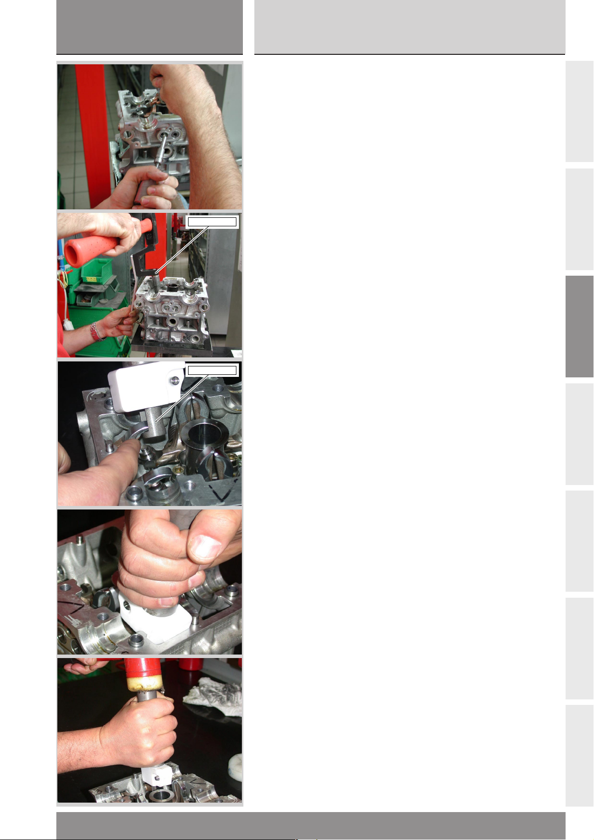
sezione / section
C
999RS04
Ricomposizione motore
Scomposizione motore
Engine reassembly
Engine disassembly
041.1.056.1A
❍
Rimuovere completamente il
perno bilanciere, il bilanciere e le
molle di richiamo (nel caso dei
bilancieri di chiusura).
❍
Per rimuovere il registro di
chiusura ed i semiconi adoperare
l’attrezzo cod. 041.1.056.1A,
picchiando con un martello come
illustrato nell’immagine, oppure
l’attrezzo cod. 041.1.055.1A.
Infilare il bilanciere di apertura, se
non è ancora stato rimosso, nella
feritoia ricavata nell’attrezzo stesso;
appoggiare l’attrezzo al bordo
interno della testa, quindi battere
con martello con battenti in plastica
sulla sommità dell’attrezzo.
❍ Remove the complete rocker arm
shaft, the rocker arm and, for closing
rocker arms only, also the return
springs.
❍
Use tool part no. 041.1.056.1A to
remove closing shim and valve
collets, tap with a hammer as
indicated in the figure or use tool
part no. 041.1.055.1A.
If not yet removed, position opening
rocker arm in the tool slot; rest the
tool on head inner edge, and tap
with a plastic hammer on top of the
tool.
A
B
C
041.1.055.1A
D
E
F
999RS - M.Y. 2004 - edizione/edition 01
G
83
Page 84
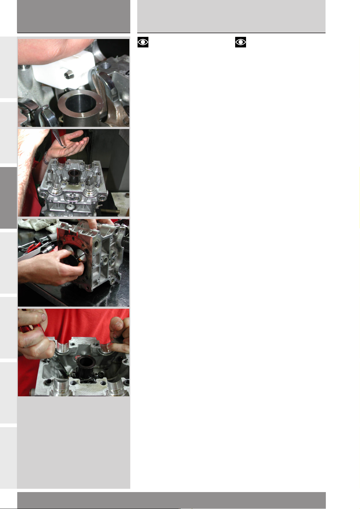
sezione / section
C
999RS04
Scomposizione motore
Engine disassembly
A
B
C
Note
L’attrezzo è realizzato in modo
che la corsa venga arrestata dal
bilanciere di chiusura onde evitare
che urti il gommino o la testa,
entrambi danneggiabili.
●
Recuperare quindi i registri di
chiusura ed i semiconi, evitando di
mescolarli se si ha l’intenzione di
riutilizzarli.
❍
Sfilare le valvole.
❍
Rimuovere i gommini di tenuta
valvola aiutandosi con una pinza.
Note
The tool is made in such a way
that the stroke stops against closing
rocker arm to prevent damages to
rubber seal or cylinder head.
●
Keep closing shims and collets. If
they have to be re-used, make sure
not to mix them.
❍
Remove valves.
❍
Remove valve rubber seals with
pincers.
D
E
F
G
84
999RS - M.Y. 2004 - edizione/edition 01
Page 85

Revisione motore
Engine overhaul
A
B
C
D
E
F
G
Page 86

sezione / section
D
999RS04
Revisione motore
Engine overhaul
INDICE DI SEZIONE
PULIZIA DEI PARTICOLARI
ACCOPPIAMENTI
A
SOSTITUZIONE ANELLI DI TENUTA OLIO
(PARAOLI)
ANELLI DI ARRESTO (SEEGER)
CUSCINETTI
CILINDRO
Modalità di misura dell’alesaggio 90
B
PISTONE
SPINOTTO
Montaggio anelli di fissaggio (circlip) dello spinotto 91
SEGMENTI
ACCOPPIAMENTO SEGMENTO-CAVA SUL
PISTONE
C
ACCOPPIAMENTO SEGMENTI-CILINDRO
SECTION INDEX
88
CLEANING PARTS
88
CLEARANCES AND FITS
CIRCLIPS
89
BEARINGS
89
CHANGING OIL SEALS
89
CYLINDER
90
Bore measuring procedure 90
PISTONS
90
GUDGEON PINS
91
Fitting the gudgeon pin circlips 91
PISTON RINGS
92
PISTON RING - PISTON GROOVE COUPLING
92
PISTON RING - CYLINDER COUPLING
93
CONNECTING RODS
88
88
89
89
89
90
90
91
92
92
93
93
IMBIELLAGGIO
SCHEDA RILEVAMENTO DATI
Biella 96
Semicuscinetti 97
Installazione cuscinetti 97
Albero motore 98
D
Accoppiamento semicuscinetti-perno biella 99
Ricomposizione imbiellaggio 99
TESTA
CONTROLLO PROFONDITÁ VALVOLE
NELLA TESTA
CONTROLLO TENUTA VALVOLE
E
VALVOLA
BILANCIERI
REGISTRI DI APERTURA E CHIUSURA - MOLLE
ALBERO A CAMME
PULEGGE - CINGHIE - TENDITORI
F
SEMICARTER MOTORE
Pulizia carter 106
CUSCINETTI DI BANCO
CIRCUITO DI LUBRIFICAZIONE
SCHEMA DI LUBRIFICAZIONE
93
DATA RECORD SHEET
Connecting rods 96
94
Assembling the bearings 97
Connecting rod bearings 97
Crankshaft 98
Connecting rod reassembly 99
Big-end bearing - crankpin clearance 99
CYLINDER HEADS
101
VALVE LEAK TEST
CHECKING THE VALVE POCKET DEPTH
102
VALVES
102
ROCKER ARMS
103
OPENING AND CLOSING SHIMS - SPRINGS
104
CAMSHAFT
104
ROLLERS - BELTS - TENSIONERS
105
CASINGS
105
Cleaning the casings 106
106
MAIN BEARINGS
LUBRICATION CIRCUIT
107
LUBRICATION CIRCUIT DIAGRAM
108
OIL PUMP
109
Cleaning the filter cartridge 110
95
101
102
102
103
104
104
105
105
106
107
108
109
110
POMPA OLIO
G
Pulizia cartuccia filtro 110
POMPA ACQUA
86
110
WATER PUMP
111
111
999RS - M.Y. 2004 - edizione/edition 01
Page 87

sezione / section
D
999RS04
Ricomposizione motore
Revisione motore
Engine reassembly
Engine overhaul
REVISIONE COMPONENTI FRIZIONE
Campana 112
Dischi 113
Controllo pacco dischi frizione 113
Piatto spingidisco 113
Tamburo 114
Flangia 114
Molle 114
Molla antisaltellamento 115
Anomalie frizione 115
GRUPPO DI RINVIO FRIZIONE
GRUPPO CAMBIO
TAMBURO COMANDO FORCHETTE
FORCHETTE SELEZIONE MARCE
SPESSORAZIONE ALBERI CAMBIO E
TAMBURO COMANDO FORCELLE
112
116
117
118
118
119
CLUTCH COMPONENTS OVERHAUL
Clutch housing 112
Clutch plates 113
Checking the clutch plates 113
Pressure plate 113
Drum 114
Flange 114
Springs 114
Anti-slip spring 115
Clutch troubleshooting 115
CLUTCH TRANSMISSION UNIT
GEARBOX
GEAR SELECTOR DRUM
GEAR SELECTOR FORKS
SHIMMING THE GEARBOX SHAFTS AND
THE FORK SELECTOR DRUM
112
116
117
118
118
119
A
B
C
D
E
F
999RS - M.Y. 2004 - edizione/edition 01
G
87
Page 88

sezione / section
D
999RS04
Revisione motore
Engine overhaul
A
B
C
PULIZIA DEI PARTICOLARI
Tutti i particolari metallici devono
essere puliti e lavati con solvente
specifico, possibilmente
biodegradabile, ed asciugati con
aria compressa.
Attenzione
Durante questa operazione si
sviluppano vapori infiammabili e
particelle di metallo possono essere
espulse ad alta velocità. Si
raccomanda di operare in un
ambiente privo di fiamme libere o
scintille e di indossare protezioni
adeguate.
Soffiare con aria compressa dentro
ai condotti di passaggio olio dei
semicarter e delle teste. Togliere
accuratamente dalle superfici di
accoppiamento eventuali tracce di
sigillante, con estrema cautela, per
non danneggiarle: utilizzare a tal
fine raschietto e diluente specifico.
Prima del rimontaggio, ripassare le
filettature di alloggiamento dei
prigionieri nei semicarter e quelle
delle viti, per eliminare i residui di
Loctite o sigillante.
CLEANING PARTS
All metal components must be
cleaned and washed using suitable
biodegradable solvents and then
dried with compressed air.
Warning
Cleaning solvents give off
inflammable fumes. Metal particles
may be projected at high speed from
engines during cleaning. Cleaning
must take place away from naked
flames or sparks. Always wear
suitable protections during cleaning
operations.
Blow through the oilways in the
casings and the cylinder heads with
compressed air. Remove residues of
sealant from all contact and
fastening surfaces. Do not damage
these surfaces. Use a suitable
scraper and solvent. Before
reassembling the engine, clean all
traces of Loctite and sealant from
the threads of the stud bolt holes in
the casings and of the screws.
D
E
F
ACCOPPIAMENTI
Per consentire al motore di
funzionare nelle migliori condizioni,
fornendo quindi il massimo
rendimento, è indispensabile che
tutti gli accoppiamenti rientrino
nelle tolleranze prescritte dalla casa
costruttrice.
CLEARANCES AND FITS
To ensure top engine performance,
all the clearances and fits must be
within the tolerances specified by
the manufacturer.
G
88
999RS - M.Y. 2004 - edizione/edition 01
Page 89
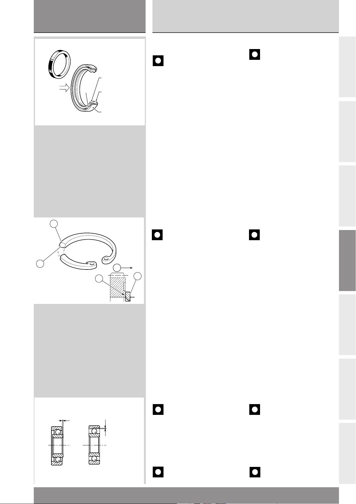
sezione / section
e
D
999RS04
Ricomposizione motore
Revisione motore
Engine reassembly
Engine overhaul
Olio
Oil
Molla
Spring
Labbro primario
Main lip
Labbro secondario
Secondary lip
Supporto
Support
SOSTITUZIONE ANELLI DI
TENUTA OLIO (PARAOLI)
Importante
Sostituire sempre i paraolio ad
ogni revisione del motore. Installare
i paraolio nuovi inserendoli
correttamente nei loro alloggiamenti
utilizzando tamponi adatti. Montare
sempre il paraolio con il lato
provvisto di molla rivolto verso la
direzione di uscita dell’olio (vedi
figura). Durante il montaggio,
lubrificare con olio motore i labbri di
tenuta del paraolio.
CHANGING OIL SEALS
Caution
Change oil seals at each
engine overhaul. Fit new oil seals
using suitable drifts.
Always fit oil seals with the spring
side facing the oil outfeed direction
(see drawing).
At reassembly, lubricate the seal
lips with a small amount of engine
oil.
A
B
C
2
1
2
F
ANELLI DI ARRESTO (SEEGER)
Importante
Sostituire sempre gli anelli di
arresto che risultano deformati o che
hanno perduto l’elasticità originale.
Tutti gli anelli di arresto presentano
un lato (1) completamente piano
con spigolo vivo e un lato (2) a
1
spigolo leggermente arrotondato.
Quando si montano nelle gole degli
alberi o nelle sedi dei coperchi, il
lato a spigolo vivo (1) deve sempre
essere opposto alla direzione della
forza (F) esercitata dall’elemento da
fermare.
CIRCLIPS
Caution
Change all circlips which are
deformed or which have lost their
original spring.
Circlips have a flat side (1) with a
sharp edge and a side (2) with a
slightly rounded edge. Circlips must
be fitted into shafts and covers
grooves with the sharp-edged side
(1) always facing the force (F)
applied by the part being held in
position.
D
E
CUSCINETTI
BEARINGS
F
Gioco assiale
Axial clearance
Gioco radiale
Radial clearanc
999RS - M.Y. 2004 - edizione/edition 01
Importante
Lavare accuratamente i
cuscinetti con benzina ed asciugarli
con aria compressa, senza farli
ruotare. Lubrificare leggermente e
ruotare lentamente a mano l’anello
interno: non si devono riscontrare
irregolarità di rotazione, attriti
anomali o giochi eccessivi.
Importante
Sostituire i cuscinetti ad ogni
revisione del motore.
Caution
Wash bearings thoroughly
with fuel. Do not rotate bearings
during washing. Dry with
compressed air.
Lightly oil the bearings. Slowly
rotate the inner ring by hand and
check for irregular rotation, jamming
and excessive play.
Caution
Use new bearings every time
engine is overhauled.
89
G
Page 90
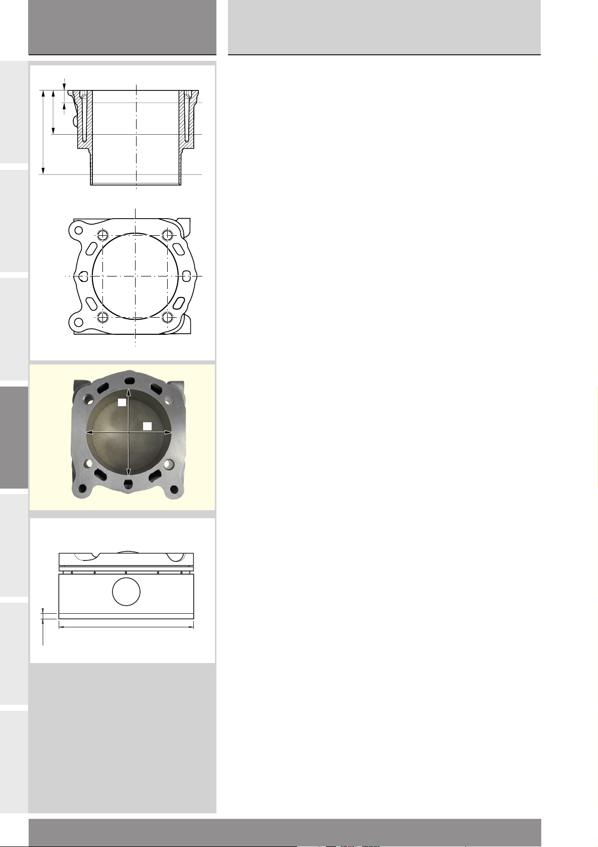
sezione / section
D
999RS04
Revisione motore
Engine overhaul
A
B
C
75
40
10
CILINDRO
Controllare che la superficie di
scorrimento del pistone sia
1
perfettamente liscia. Controllare la
misura dell’alesaggio.
2
Modalità di misura
dell’alesaggio
La misura dell’alesaggio deve
essere realizzata su 3 piani (1), (2) e
3
(3) distanti dal piano testa - cilindro
risp. 10, 40, 75 mm e lungo due
direzioni: asse spinotto (A) e asse
perpendico-lare ad esso (B) (tot. sei
misure). L’alesaggio si ottiene come
media delle sei misure così
effettuate. perpendicolare allo
spinotto. L’alesaggio deve risultare
compreso tra 104,01 ÷ 104,02 mm.
CYLINDER
Check that the walls are perfectly
smooth. Check bore size.
Bore measuring procedure
Bore shall be measured on three
different flat surfaces (1), (2) and (3)
at a distance of 10, 40 and 75 mm
respectively from the cylinder-head
and along two directions: gudgeon
pin axis (A) and the axis (B)
perpendicular to this one (six
readings in total). Bore is the
average value of the six readings
taken perpendicularly to the
gudgeon pin. Bore should be
between 104.01 and 104.02 mm.
D
E
F
G
4 mm
A
B
PISTONE
Dopo aver rimosso i segmenti,
pulire accuratamente il cielo del
pistone e le cave dei segmenti dalle
incrostazioni carboniose. Procedere
ad un accurato controllo visivo e
dimensionale del pistone: non
devono apparire tracce di
forzamenti, rigature, crepe o altri
danni.
Misurare il diametro del pistone a
4 mm dalla base del mantello, in
direzione perpendicolare all’asse
dello spinotto. La misura del pistone
deve risultare compresa tra 103,917
÷ 103,923 mm.
Per determinare il gioco di
accoppiamento pistone cilindro
bisogna confrontare la misura del
diametro del pistone con la media
delle tre misure di diametro del
cilindro effettuate nella direzione
ortogonale all’asse spinotto.
- Gioco di accoppiamento con il
cilindro:
0,090 ÷ 0,100 mm.
PISTONS
Remove piston rings. Clean all
carbon deposits from the ring
grooves and the piston crowns.
Thoroughly check pistons for wear
or damage. There must be no
scoring, scuffing, cracks or visible
damage.
Measure the piston diameter at
4 mm from the skirt base at right
angles to the axis of the gudgeon
pin. Piston size should be between
103.917 mm and 103.923 mm .
Compare piston diameter with the
average value of the three cylinder
diameters taken at right angles to
the gudgeon pin axis to determine
cylinder-piston coupling clearance.
- Cylinder coupling clearance:
0.090 - 0.100 mm.
90
999RS - M.Y. 2004 - edizione/edition 01
Page 91
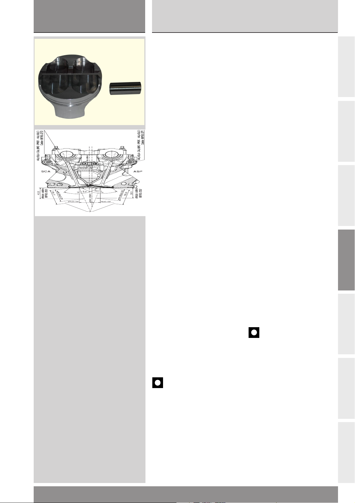
sezione / section
D
999RS04
Ricomposizione motore
Revisione motore
Engine reassembly
Engine overhaul
SPINOTTO
Deve risultare perfettamente
lappato, senza rigature, scalini o
colorazioni bluastre dovute a
eccessivo riscaldamento. Lo
spinotto ben lubrificato deve poter
scorrere all’interno della sede del
pistone senza forzature.
Montaggio anelli di fissaggio
(circlip) dello spinotto
❍ Inserire lo spinotto nelle portate
del pistone.
● Inserire l’estremità dritta del circlip
all’interno del foro presente nella
portata del pistone collocando l’altra
estremità del circlip nel lato del
pistone in cui è presente lo smanco
per agevolare l’estrazione del circlip.
Inserire l’attrezzo speciale cod.
041.1.079.1C nel foro dello spinotto
con lo smusso dell’attrezzo verso
l’alto avendo cura di tenere lo
spinotto in posizione.
● Ruotare di 90° in senso antiorario
l’attrezzo speciale.
❍ Spingere assialmente l’attrezzo
per avvicinare l’anello alla portata del
pistone.
● Ruotare di 360° l’attrezzo
spingendo assialmente per inserire
completamente il circlip.
● Assestare il circlip inserito,
utilizzando l’apposito tampone cod.
041.1.038.1A battendo il circlip dal
lato esterno contro lo smusso dello
spinotto
● Misurare con il calibro il diametro
interno d
dell’estremità libera ed il diametro
interno d
riportare i valori nell’apposito foglio
di montaggio.
● La misura deve essere compresa
rispettivamente nell’intervallo 18,20-
18,24 mm e nell’intervallo 18,0918,13 mm.
- Gioco diametrale di
dell’anello in prossimità
2
nella direzione ortogonale;
1
accoppiamento con pistone:
0,015 ÷ 0,023 mm
GUDGEON PINS
Gudgeon pins must be smooth,
without scoring, stepping or blue
overheating marks. A well lubricated
gudgeon pin must rotate smoothly
and easily in its seat.
Fitting the gudgeon pin
circlips
❍ Fit the gudgeon pin in its seat in
the piston.
● Fit the circlip straight end in the
hole on the piston seat and fit the
other circlip end on the waisted
piston side featured to ease circlip
removal.
Fit the special tool part no.
041.1.079.1C in the gudgeon pin
hole with the tool chamfer up, make
sure to keep the gudgeon pin in
position.
● Turn the special tool by 90°
counter-clockwise.
❍ Push the tool axially to bring the
ring close to piston seat.
● Turn the tool by 360° and push
axially to fit the circlip fully home.
● Use the suitable drift part no.
041.1.038.1A to tap onto circlip from
outside toward gudgeon pin
chamfer to settle it.
● Measure with a dial gauge the
inner diameter d
open end and inner diameter d
right angles; note the values on the
relevant assembly sheet.
● The reading must be respectively
within the range 18.20-18.24 mm
and 18.09-18.13 mm.
- Piston coupling clearance on the
diameter:
0.015 - 0.023 mm
Caution
Change worn gudgeon pins.
Gudgeon pins are matched with
pistons. If you change the gudgeon
pin, you must also change the
piston.
of the ring at the
2
1
at
A
B
C
D
E
999RS - M.Y. 2004 - edizione/edition 01
Importante
Se le condizioni di usura non
permettono il riutilizzo dello
spinotto, sostituirlo assieme al
relativo pistone.
F
G
91
Page 92
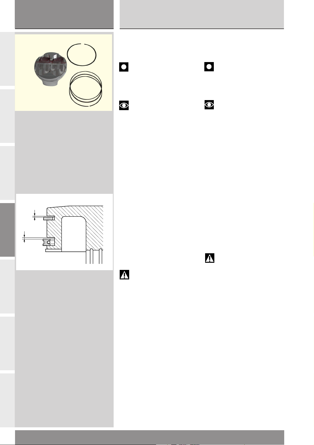
sezione / section
D
999RS04
Revisione motore
Engine overhaul
A
B
C
SEGMENTI
Non devono presentare tracce di
forzamenti o rigature.
Importante
Sostituire sempre i segmenti
ad ogni revisione, consultando la
tabella degli intervalli di
manutenzione riportata all’inizio del
manuale.
Note
Il segmento superiore deve
essere montato con la “R” rivolta
verso l’alto.
PISTON RINGS
Piston rings must be free of scoring,
scuffing and signs of forcing.
Caution
Change piston rings at each
engine overhaul, respecting the
intervals indicated in the
maintenance schedule.
Note
Upper piston ring shall be
assembled with the “R” marking
facing up.
D
E
F
ACCOPPIAMENTO
SEGMENTO-CAVA SUL
PISTONE
La figura riporta il corretto gioco
assiale che deve presentare il
segmento nella relativa cava del
pistone.
- Gioco assiale segmento
superiore:
0,03 ÷ 0,07 mm
- Gioco assiale raschiaolio:
0,04 ÷ 0,12 mm
Attenzione
In caso di sostituzione dei
segmenti, controllare sempre prima
del montaggio il gioco assiale dei
segmenti nuovi nel pistone.
PISTON RING - PISTON
GROOVE COUPLING
The figure shows the correct axial
play of the piston rings inside the
piston grooves.
- Upper piston ring axial play:
0.03 ÷ 0.07 mm
- Scraper ring axial play:
0.04 ÷ 0.12 mm
Warning
When changing piston rings,
always check their axial play inside
piston before assembly.
G
92
999RS - M.Y. 2004 - edizione/edition 01
Page 93
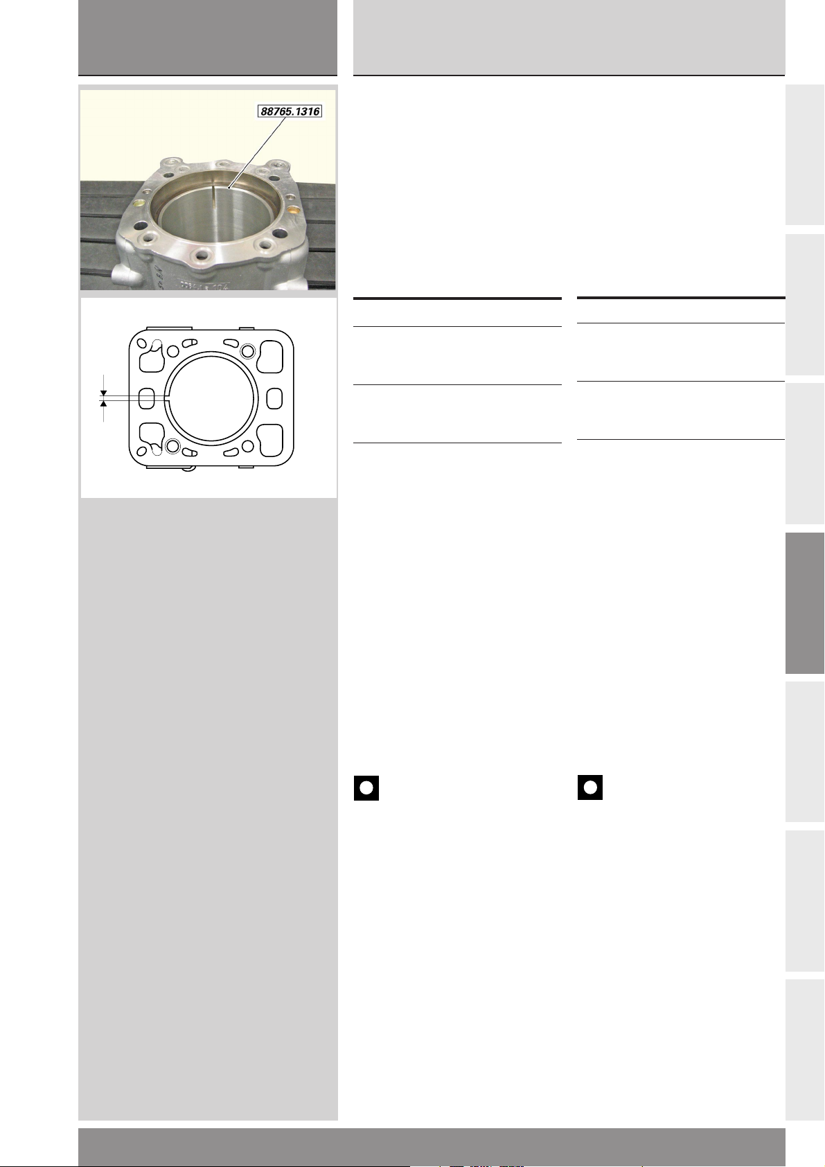
sezione / section
D
999RS04
Ricomposizione motore
Revisione motore
Engine reassembly
Engine overhaul
ACCOPPIAMENTO SEGMENTICILINDRO
Infilare il tampone cod. 88765.1316
per la misura delle luci dei segmenti
all’interno del cilindro.
Posizionare i segmenti sopra il
tampone facendo corrispondere la
cava del tampone con la luce del
segmento.
Misurare con uno spessimetro la
luce del segmento.
Il gap così misurato deve essere pari
a:
Sezione cilindro
1° segmento
121.1.105.1A 0,08÷0,21
Raschiaolio
121.1.106.1A 0,23÷0,76
N.B. Se il gioco è insufficiente,
limare il segmento o sceglierne uno
di lunghezza differente.
PISTON RING - CYLINDER
COUPLING
Fit tool part no. 88765.1316 to
measure piston rings gap inside the
cylinder.
Position the piston rings on the tool,
make the tool groove match with
the piston ring gap.
Measure the ring end gap with a
feeler gauge.
The readings should be the
following:
Cylinder section
1st piston ring
121.1.105.1A 0.08-0.21
Oil scraper ring
121.1.106.1A 0.23-0.76
N.B. If gap is below the specified
limits, file ring or choose a different
one.
A
B
C
IMBIELLAGGIO
Scomporre l’imbiellaggio separando
le bielle dall’albero motore.
Importante
Fare attenzione a non
scambiare le bielle tra loro e a
mantenere l’orientamento originale,
con la scritta “PANKL” rivolta verso
l’esterno (estremità albero motore,
cioé visibile ad imbiellaggio chiuso
con bielle affiancate).
Per agevolare i tecnici addetti alla
revisione dei componenti
l’imbiellaggio riportiamo un facsimile di “Scheda rilevamento dati”,
da utilizzare come documento per la
trascrizione e per l’archivio dei dati
rilevati sul motore.
CONNECTING RODS
Remove the connecting rods from
the crankshaft.
Caution
Do not mix up the connecting
rods and reassemble them in their
original positions. Be sure the
“PANKL” wording is facing outwards
(crankshaft end - this means it
should be visible with the
connecting rods reassembled and
lined up side by side).
To facilitate the work of the
mechanic overhauling the con-rods
we have provided the following copy
of a “Data record sheet”. Use this
sheet to record and file engine data
measured during work.
D
E
F
999RS - M.Y. 2004 - edizione/edition 01
G
93
Page 94
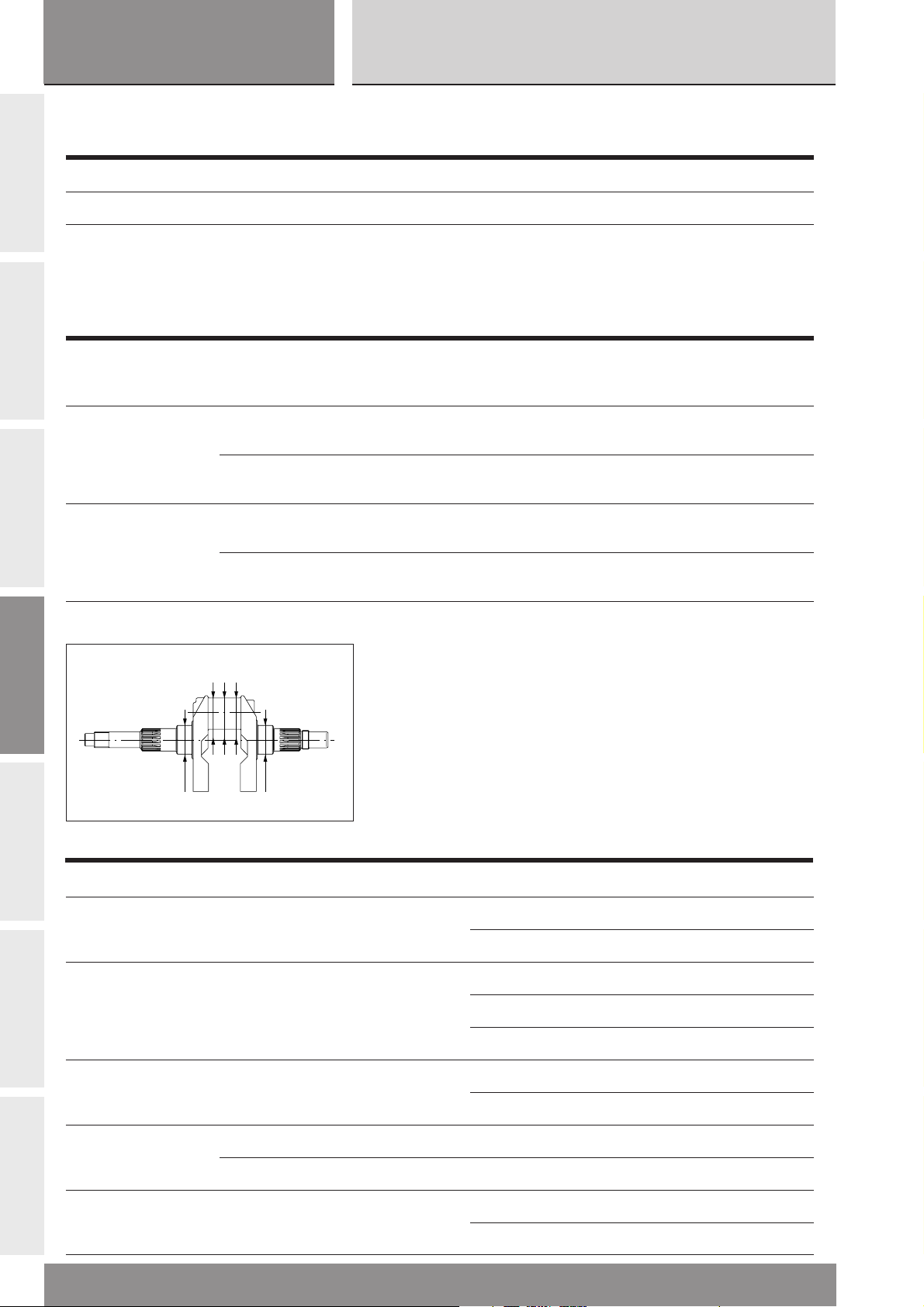
sezione / section
D
Fac-simile
SCHEDA RILEVAMENTO DATI
999RS04
Revisione motore
Engine overhaul
A
B
C
motore numero montaggio numero data
albero motore n° = km = Bielle km
Procedura di serraggio
numero numero posizione numero spessore o lunghezza lunghezza allung. coppia coppia
biella e serraggi viti serraggio selezione iniziale finale viti finale di disselezione biella viti bronzine viti viti serraggio serraggio
lato lato
frizione numero
N°
lato
selezione
lato lato
alternatore numero
N°
lato
selezione
M9x1 1)Sgrassare superfici biella e viti con DET AT/AI CR
2) Lubrificare vite e sottotesta con GREASE E
3) Serrare per avvicinamento con allungamento di 0,050±0,005 mm
4) Proseguire il serraggio fino alla lettura di un allungamento pari a
0,175±0,005 mm
D
E
F
2
Lato
34
alternatore
15
campo tolleranza posizione valore misurato
perno di banco 34,988 ÷ 34,972 mm lato frizione (5)
perno di biella Selezione A: 42,006 ÷ 42,014 mm lato frizione (4)
Selezione B: 41,998 ÷ 42,006 mm
diametro testa Selezione A: 46,021 ÷ 46,025 mm lato frizione
di biella Selezione B: 46,017 ÷ 46,021 mm
Lato
frizione
lato alternatore (1)
centro (3)
lato alternatore (2)
lato alternatore
G
diametro testa di lato frizione d25° = d0° = d25° = dm =
biella con bronzine
lato alternatore d25° = d0° = d25° = dm =
accoppiamento 0,055 ÷ 0,065 mm lato frizione
nominale
biella-perno di biella lato alternatore
94
999RS - M.Y. 2004 - edizione/edition 01
Page 95
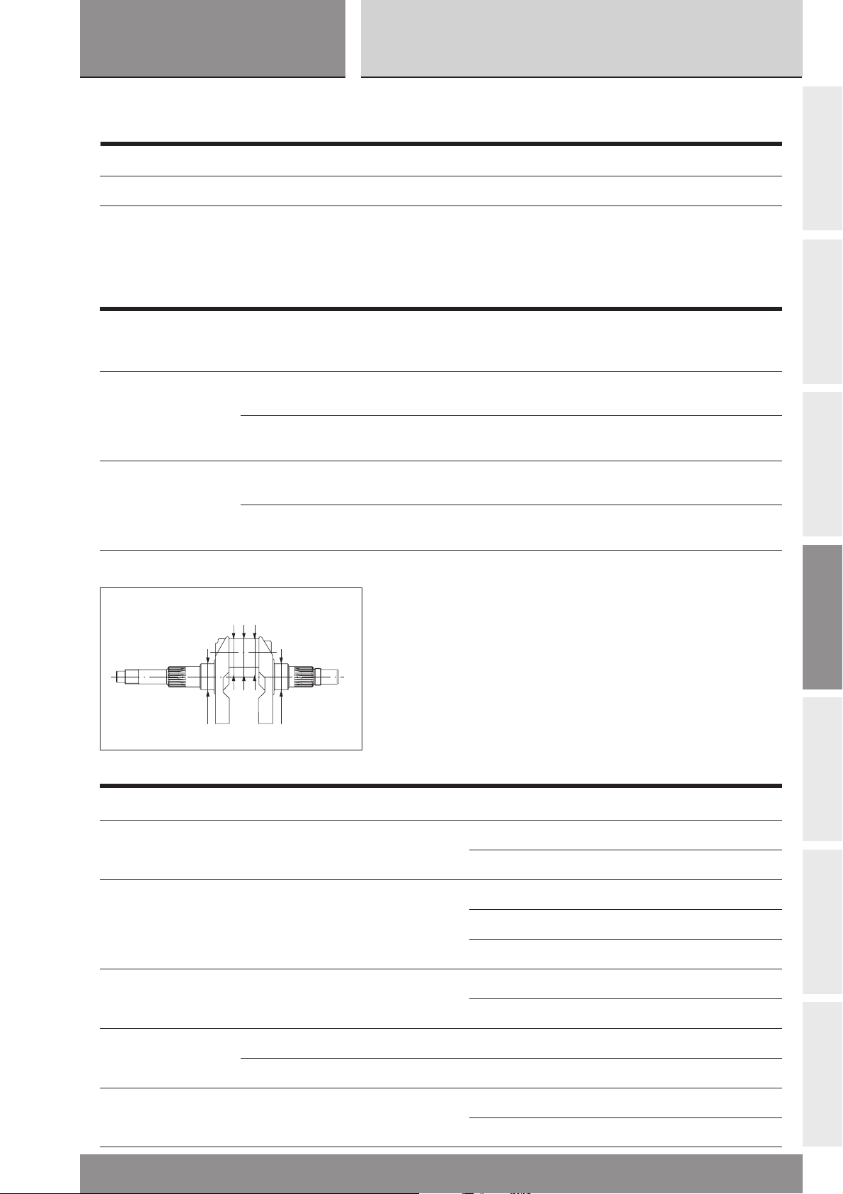
sezione / section
D
Facsimile
DATA RECORD SHEET
999RS04
Ricomposizione motore
Revisione motore
Engine reassembly
Engine overhaul
Engine number Assembly number Date
Crankshaft no. = km = Con-rods km
Tightening
procedure
con-rod con-rod screw screw bear. shell screw screw screw final final
and class tightenings position tightenings thick. or initial final stretch tight. loos.
number number number class length length torque torque
clutch number
side side
no.
alternator number
side side
no.
M9x1 1)Degrease con-rod and bolt surfaces using DET AT/AI CR
2) Lubricate screw and underside with GREASE E
3) Tighten for snugging with a stretch of 0.050±0.005 mm
4) Continue tightening until reading a stretch of 0.175±0.005 mm
class
side
class
side
A
B
C
2
3
Alternator
4
side
15
tolerance range position measured value
Main bearing 34.988 - 34.972 mm clutch side (5)
Crankpin Class A: 42.006 - 42.014 mm clutch side (4)
Class B: 41.998 - 42.006 mm
Con-rod big-end Class A: 46.021 - 46.025 mm clutch side
diameter Class B: 46.017 - 46.021 mm
Clutch
side
alternator side (1)
center (3)
alternator side (2)
alternator side
D
E
F
Con-rod big-end clutch side d25° = d0° = d25° = dm =
diameter with bearings
alternator side d25° = d0° = d25° = dm =
Con-rod - crank pin 0.055 - 0.065 mm clutch side
nominal coupling
alternator side
999RS - M.Y. 2004 - edizione/edition 01
G
95
Page 96
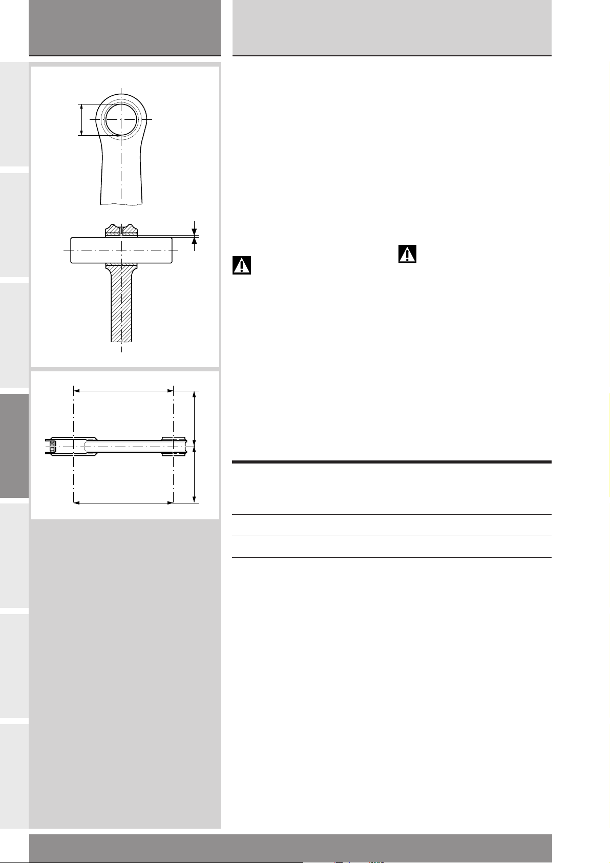
sezione / section
D
999RS04
Revisione motore
Engine overhaul
A
B
C
D
Procedere alla revisione dei
componenti l’imbiellaggio:
Biella
La boccola sul piede di biella deve
risultare in buone condizioni e
saldamente piantata nel proprio
alloggiamento.
- Diametro nominale boccola piede
di biella:
20,040 ÷ 20,045 mm
- Gioco di accoppiamento nominale
boccola piede di biella-spinotto:
0,040 ÷ 0,051 mm
In caso di usura eccessiva sostituire
la biella.
Attenzione
I pezzi in titanio devono
essere maneggiati con la massima
cura. Anche piccoli urti possono
causare cricche invisibili ad occhio
nudo che producono rotture per
fatica in funzionamento.
Controllare l’errore di parallelismo
rilevato a 100 mm dall’asse
longitudinale della biella. Deve
H
100 mm
risultare:
H - h inferiore a 0,02 mm
In caso contrario sostituire la biella.
Ogni biella è classificata da due
selezioni A e B, punzonate sulla
testa, riferite all’accoppiamento con
l’albero motore.
Proceed to connecting rods overhaul
as follows:
Connecting rods
The small-end bush must be in good
conditions and securely located into
its seat.
- Nominal diameter of small-end
bush:
20.040 - 20.045 mm
- Small-end bush-gudgeon pin
nominal play:
0.040 - 0.051 mm
If the bush is excessively worn,
change the con-rod.
Warning
Handle titanium parts with
great care. Even minor damage can
cause cracks invisible to the eye that
will lead to fatigue failure during
operation.
Measure the straightness error at
100 mm from the con-rod
longitudinal axis. The straightness
error must be:
H - h less than 0.02 mm
In the event of a greater error,
change the con-rod.
Con-rods are classified, and marked
on their big ends, as two classes, A
and B, indicating their coupling with
the crankshaft.
E
F
Selezione Diametro nominale testa di
h
100 mm
Class Con-rod big-end nominal
A 46,021 ÷ 46,025 mm
B 46,017 ÷ 46,021 mm
Eliminare dal cappello e dallo stelo,
operando con tela abrasiva N. 400
bagnata nel solvente usato per
sgrassare il particolare, le eventuali
segnature prodotte dal retro della
bronzina.
biella
diameter
Using emery cloth N. 400 soaked in
a degreaser, rub away any marks
left by the back of the bearing shell
on the cap and the stem.
G
96
999RS - M.Y. 2004 - edizione/edition 01
Page 97
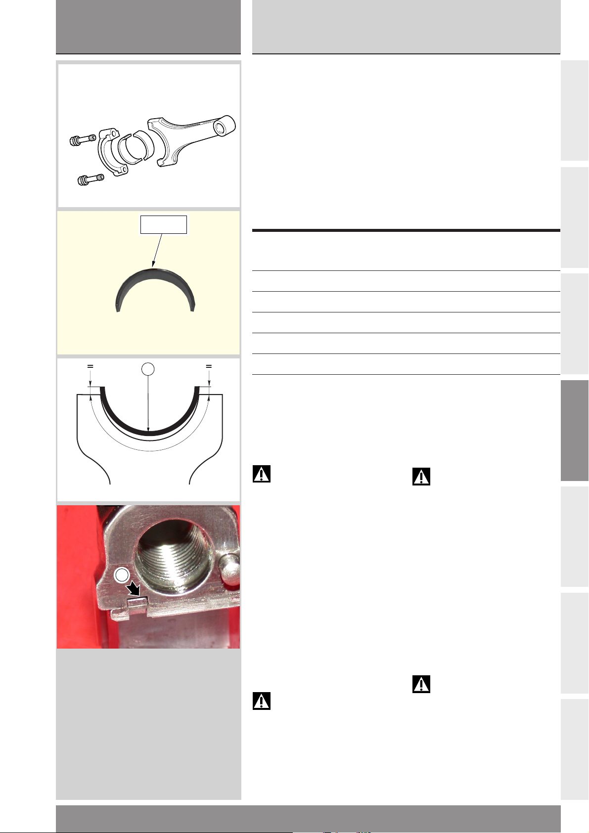
sezione / section
D
999RS04
Ricomposizione motore
Revisione motore
Engine reassembly
Engine overhaul
COLORE
COLOR
F
Semicuscinetti
È buona norma sostituire i
semicuscinetti ad ogni revisione o
comunque secondo gli intervalli
prescritti nella tabelle delle
manutenzioni periodiche riportata
nella sezione B.
I semicuscinetti nuovi vengono
forniti già pronti per il montaggio e
non devono essere ritoccati con
raschietti o tela smeriglio.
Appartengono a sei classi
dimensionali identificabile ciascuna
da un colore (GIALLO, ROSSO,
ROSSO-NERO, BLU-NERO, NERO,
BLU).
Colore Codice Dimensione
Colors Part no. Nominal Size
Blu-Nero
Blue-Black
Rosso-Nero
Red-Black
Rosso
Red
Blu
Blue
Giallo
Yellow
Nero
Black
Installazione cuscinetti
I semicuscinetti, e quindi il loro
alloggiamento nella testa di biella,
sono dotati di due dentini per tenerli
in posizione.
112.1.023.1AG 1,979 ÷ 1,984
112.1.023.1AF 1,983 ÷ 1,988
112.1.023.1AA 1,987 ÷ 1,992
112.1.023.1AB 1,991 ÷ 1,996
112.1.023.1AC 1,995 ÷ 2,000
112.1.023.1AD 1,999 ÷ 2,004
Connecting rod bearings
Change the bearings every time the
engine is overhauled or at regular
intervals as specified in the
maintenance schedule table of
Section B.
Spare bearings are supplied ready
for fitting. They must not be
reworked with scrapers or emery
cloth.
These bearings can belong to six
different size classes identified by
different colors (YELLOW, RED,
RED-BLACK, BLUE-BLACK, BLACK,
BLUE).
nominale
Assembling the bearings
Bearings, as well as their location
inside con-rod big end, are provided
with two small teeth holding them
in place.
A
B
C
D
Attenzione
La bronzina è dotata di due
denti. Il verso di montaggio è
indifferente.
●
Appoggiare il semicuscinetto sulla
testa o sul cappello di biella in modo
che la sporgenza delle estremità
rispetto alla superficie di unione
risulti equidistante.
●
A
Verificare anche che risulti
centrato assialmente nella testa o
nel cappello di biella.
●
Con le dita spingere il
semicuscinetto in sede facendo
pressione (F) sulla mezzeria del
cuscinetto.
●
Eliminare eventuali bave che
possono formarsi nello sfregamento
dell’estremità del cuscinetto con lo
spigolo della sede sulla biella.
Attenzione
Verificare che esista
comunque un po’ di gioco (A), tra il
dente del semicuscinetto e il vano
del dente su bronzina (o sul
cappello), onde evitare che il dente
allontani il semicuscinetto dalla
biella (o dal cappello).
Warning
The con-rod bearing features
two small teeth. It does not matter
in which direction you fit it.
●
Put the bearing onto the
connecting rod big end or cap so
that an equal portion of bearing
protrudes over the big end on either
side.
●
Make sure it is properly centered
with the big end or cap axis.
●
Press onto the bearing axis (F)
with your fingers and seat it
properly.
● Remove any burrs due to bearing
edge friction against the seat on the
con-rod.
Warning
Check that between bearing
tooth and tooth location on
the bearing shell (or cap) there is
some clearance (A) in order to avoid
that bearing is not moved away from
connecting rod (or cap) by the tooth.
E
F
G
999RS - M.Y. 2004 - edizione/edition 01
97
Page 98
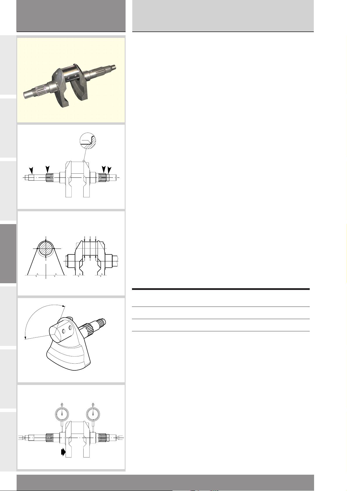
sezione / section
D
999RS04
Revisione motore
Engine overhaul
A
B
C
D
Albero motore
Pulire con estrema cura le
canalizzazioni olio interne all’albero,
adoperando liquido sgrassante tipo
DETA T / AL ed aria compressa.
Procedere al controllo visivo
dell’albero motore: i perni di banco
e di biella non devono presentare
solchi o rigature. Eventualmente
levigare la superficie con tela
abrasiva finissima e olio. Verificare
che nella zona di raccordo tra perno
e spallamento non vi siano segni di
lavoro o bave.
- Raggio di raccordo:
2 mm
2 mm
1
2
a
bc
Le filettature, le sedi delle linguette
e le scanalature devono essere in
buone condizioni.
Rilevare la rettilineità e la circolarità
del perno di biella.
Per la rettilineità, effettuare tre
misure su tre generatrici a 120° per
metà della lunghezza del perno
(valore nominale max. 0,005 mm).
Per la circolarità effettuare tre
misure sul piano di mezzeria e tre a
90° da queste (valore nominale max.
0,005 mm).
Rilevare con comparatore
l’allineamento dei perni di banco,
posizionando l’albero motore tra due
contropunte:
- Errore di allineamento nominale:
0,01 mm
Ogni albero motore è classificato da
due selezioni A e B, punzonate sul
fianco mannaia, lato pignone,
riferite al perno di biella.
Crankshaft
Thoroughly clean shaft oil inner
ducts with a degreaser such as
DETA T / AL and blow with
compressed air.
Visually inspect the crankshaft. The
main bearings and the crankpins
must not be scored or grooved. If
necessary, polish the surface with
fine emery cloth soaked in oil. Check
that the area between the bearing
and the shoulder is free from wear
or burrs.
- Radius:
2 mm
Check that the threads, keyways
and splines are in good condition.
Measure the straightness and
roundness of crank pin.
Make three readings on three
generating lines at 120° for half of
the pin length (max. nominal value
0.005 mm) to measure straightness.
Make three readings on the center
surface and three at 90° from the
first points (max. nominal value
0.005 mm) to measure roundness.
Fit the crankshaft between two
centers and then use a dial gauge to
check the alignment of the main
bearings.
- Nominal alignment error:
0.01 mm
Crankshafts are classified in two
types: A and B. The type is punched
on the side of the crank web on the
sprocket side close to the main
bearing.
E
F
G
120˚
Selezione
Type
Selezione Diametro nominale
Type Nominal diameter
A 42,006 ÷ 42,014 mm
B 41,998 ÷ 42,006 mm
98
999RS - M.Y. 2004 - edizione/edition 01
Page 99
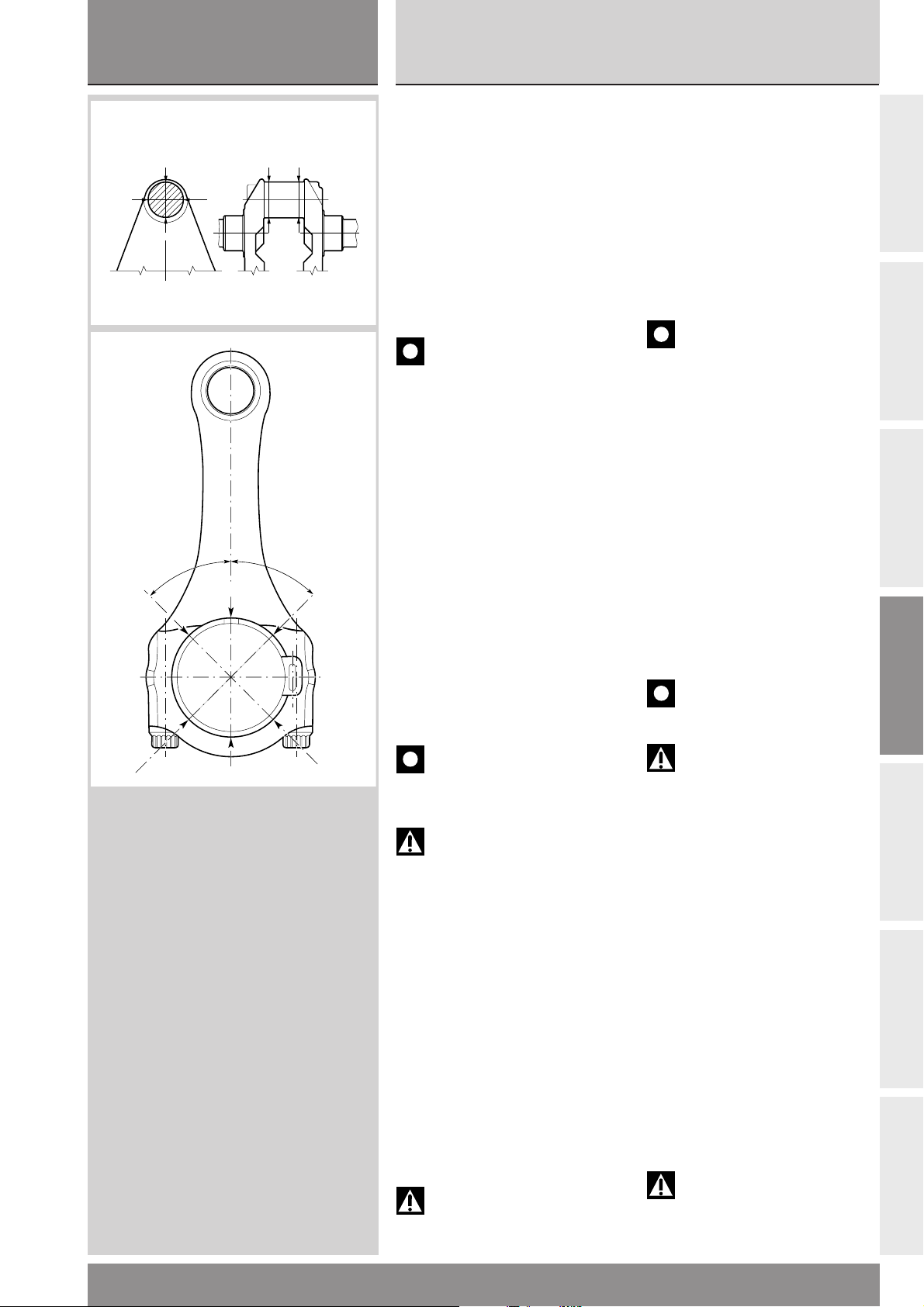
sezione / section
D
999RS04
Ricomposizione motore
Revisione motore
Engine reassembly
Engine overhaul
1
2
45˚ 45˚
a
d
fe
Accoppiamento
semicuscinetti-perno biella
Per verificare il gioco di
b
accoppiamento tra semicuscinetti e
albero motore procedere come
segue:
●
Rilevare il diametro del perno di
biella in posizioni intermedie ed
equidistanti (a - b).
In riferimento agli assi ortogonali
(1 - 2), determinare il valore medio.
▲
Serrare le viti della biella, alla
coppia prescritta sezione B (senza
semicuscinetti).
Importante
Per svolgere le operazioni di
verifica del gioco di accoppiamento
è consigliato utilizzare delle viti di
biella di servizio, evitando così un
ulteriore serraggio delle viti da gara.
Le viti da gara, infatti, possono
subire al massimo tre serraggi.
●
Rilevare il diametro interno della
biella, in riferimento agli assi (d - e - f)
e determinare il valore medio.
●
Applicare la formula:
SPESSORE SEMICUSCINETTO =
(DIAMETRO BIELLA - DIAMETRO
PERNO - K) / 2
K = 0,037 mm
Gioco di accoppiamento nominale:
0,060 ± 0,005 mm
Scegliere lo spessore dei semicuscinetti nella classe di appartenenza,
che permetta la migliore centratura.
Big-end bearing - crankpin
clearance
To check the clearance between the
big-end bearings and the crankpin
proceed as follows:
●
Measure the crankpin diameter in
intermediate and equidistant
positions (a - b).
Calculate the average value at right
angles (1 - 2).
▲
Tighten the con-rod bolts to the
specified torque (Section B) (without
bearings).
Caution
To check coupling clearance,
use service con-rod bolts in order to
avoid one more tightening of racing
bolts. Racing bolts can be used for a
total of three tihtenings only.
●
Measure the internal diameter of
the con-rod with reference to (d - e f) axes. Calculate the average value.
●
Use the formula:
BEARING THICKNESS = (CON-ROD
DIAMETER - CRANKPIN DIAMETER K) / 2
K = 0.037 mm
Nominal clearance:
0.060 - 0.005 mm
Select a bearing for proper centering
(refer to bearing classes).
Caution
Do not use con-rods with
clearances of less than 0.055 mm.
A
B
C
D
Importante
Evitare di utilizzare imbiellaggi
che presentano un gioco inferiore a
0,055 mm.
Attenzione
I pezzi in titanio devono essere
maneggiati con la massima cura.
Anche piccoli urti possono causare
cricche invisibili ad occhio nudo che
producono rotture per fatica in
funzionamento.
Ricomposizione imbiellaggio
● Verificare che su ogni biella, tra
cappello e il relativo fusto, siano
montate le spine di centraggio.
●
Pulire accuratamente bielle e viti
bielle con solvente sgrassante DETA
T/AI CR, adoperando degli scovolini
in nylon Ø 15 mm.
●
Lubrificare con grasso GREASE E il
filetto e il sottotesta delle viti nuove
e la sede filettata sul fusto,
introducendo grasso dalle due
estremità del foro.
Attenzione
Il grasso utilizzato è irritante al
contatto con la pelle; indossare
guanti protettivi.
Warning
Handle the titanium parts with
great care. Even minor damage can
cause cracks invisible to the eye that
will lead to fatigue failure during
operation.
Connecting rod reassembly
● Check that centering pins are
positioned between the cap and
shaft of all connecting rods.
●
Thoroughly clean all connecting
rods and bolts with DETA T/AI CR
degreaser and nylon brushes Ø 15
mm.
●
Lubricate the new bolt underside
and the threaded hole on the shaft
with GREASE E. Fill grease from
both sides of the hole.
Warning
Corrosion and irritant hazard.
The grease used is corrosive. Avoid
contact with skin and wear
protective gloves.
E
F
G
999RS - M.Y. 2004 - edizione/edition 01
99
Page 100

sezione / section
D
999RS04
Revisione motore
Engine overhaul
A
B
C
D
E
Importante
La lubrificazione delle viti di
biella è fondamentale per ottenere
l’accoppiamento prescritto ed
evitare la rottura dei componenti.
Le viti di biella possono essere
utilizzati solo per tre serraggi.
▲
Montare le bielle (con bronzine)
sull’albero avvitando a mano le viti
nella biella senza serrarle.
●
Inserire tra le teste di biella
l’apposita forchetta-distanziale per
annullare il gioco assiale bielle-perno
ed inserire lo spinotto nei piedi di
biella allineati.
●
Posizionare i due comparatori
PANKL sulle due viti di una stessa
biella ed azzerarli.
●
Applicare un serraggio “di
avvicinamento” allungando prima
una e poi l’altra vite di 0.050 ± 0.005
mm.
●
Proseguire il serraggio su
entrambe le viti fino a leggere un
allungamento totale pari a 0.175 ±
0.005 mm.
●
Ripetere sulla seconda biella.
Importante
Nel maneggiare e
movimentare le bielle in titanio
occorre prestare la massima
attenzione ad evitare urti con corpi
duri, che possono intaccare gli
spigoli della biella creando pericolosi
effetti di intaglio. In particolar modo
si deve assolutamente evitare l’urto
della costa della biella sui bordi del
foro di montaggio dei cilindri sul
carter, durante tutte le operazioni di
montaggio/revisione nelle quali si
trascina a mano l’albero senza che
siano montati i gruppi cilindro pistone. A tal fine si consiglia di
utilizzare la flangia parabordi in PVC
(cod. 041.1.029.2A) da infilare nel-
l’ apertura carter onde evitare urti
che potrebbero danneggiare le
bielle.
Caution
Con-rod bolts lubrication is
critical for a correct coupling and to
avoid parts breakage.
Con-rod bolts may be used for a total
of 3 tightenings only.
▲
Fit the con-rods (with bearings)
onto the shaft, snug bolts by hand
and do not tighten them yet.
●
Fit the suitable fork-shaped spacer
in-between the big ends to take up
any axial play between con-rod and
crank pin. Align the small ends and
fit the gudgeon pin.
●
Fit the two PANKL dial gauges on
the two bolts of the same con-rod
and reset the gauges.
●
First snug the bolts so to stretch
them one at a time by 0.050 ± 0.005
mm.
●
Tighten both screws until reading
a total stretch of 0.175 ± 0.005 mm.
●
Repeat procedure for the bolts on
the other connecting rod.
Caution
Handle titanium parts with
great care. Take care to avoid
impacts with hard bodies that could
damage the con-rod edges and lead
to dangerous notch effects. Avoid
impact of con-rod face with the
cylinder hole edges for fitting on
casing during all the assembly/
overhaul operations where
crankshaft is turned by hand without
the cylinder-piston assemblies. To
this end, to avoid possible impacts
leading to connecting rod damages,
the use of PVC bumper flange (part
no. 041.1.029.2A) to be installed
into the casing opening is strongly
recommended.
F
G
100
999RS - M.Y. 2004 - edizione/edition 01
 Loading...