

Ducane (HVAC) SH13 User Manual
INSTALLATION AND
MAINTENANCE INSTRUCTIONS
(2,4)SH13 Series
Self-Contained Heat Pump
WARNING
Improper installation, adjustment, alteration, service, or maintenance can cause injury or
property damage. Refer to this manual. For assistance or additional information, consult a
qualified installer or service agency.
WARNING
Installation and servicing of air conditioning
equipment can be hazardous due to internal
refrigerant pressure and live electrical components. Only trained and qualified service
personnel should install or service this equipment. Installation and service performed by
unqualified persons can result in property
damage, personal injury, or death.
WARNING
If this unit is to be installed in a mobile or manufactured home application, the ductwork must
be sized to achieve static pressures within the
manufacturer’s guidelines. All other installation
guidelines must also be followed. Failure to do
so may result in equipment damage, personal
injury, and improper performance of the unit.
*48369K005*
WARNING
Sharp metal edges can cause injury. When
installing the unit, use care to avoid sharp
edges.
TABLE OF CONTENTS
INSTALLATION ...................................... 2
OPERATION .......................................... 7
MAINTENANCE................................... 10
WIRING DIAGRAM .............................. 11
WARRANTY ........................................ 12
Manufactured By
A.A.C.
A Lennox International Inc. Company
421 Monroe Street
Bellevue, OH 44811
CAUTION
The installation of this appliance must conform to the requirements of the National Fire Protection Association;
the National Electrical Code, ANSI/NFPA No. 70 (latest edition) in the United States; the Canadian Electrical
Code Part 1, CSA 22.1 (latest edition) in Canada; and any state or provincial laws or local ordinances. Local
authorities having jurisdiction should be consulted before installation is made. Such applicable regulations or
requirements take precedence over the general instructions in this manual.
# 48369K005 Page 1
Save these instructions for future reference
INSTALLATION
Location
These instructions explain the recommended method of
installation of the SH heat pump unit and associated
electrical wiring.
This unit is designed and approved for use as a selfcontained air-to-air outdoor heat pump system.
The units are factory equipped with a transformer and
blower control for applications without auxiliary heat.
Electric heat accessory kits (PHK) can be ordered for field
installation of additional heat where required.
These instructions, and any instructions packaged with
mating components and/or accessories, should be carefully read prior to beginning installation. Note particularly
any CAUTIONS or WARNINGS in these instructions and
all labels on the units.
These instructions are intended as a general guide only, for
use by qualified personnel and do not supersede any national
or local codes in any way. Compliance with all local, state,
provincial, or national codes pertaining to this type of
equipment should be determined prior to installation.
IMPORTANT: This product has been designed and manufactured to meet ENERGY STAR criteria for energy efficiency.
However, proper refrigerant charge and proper air flow are
critical to achieve rated capacity and efficiency. Installation
of this product should follow the manufacturer’s refrigerant
charging and air flow instructions. Failure to confirm
proper charge and airflow may reduce energy efficiency and shorten equipment life.
The unit is designed to be located outdoors with sufficient
clearance for free entrance to the air inlet and discharge air
openings. The location must also allow for adequate
service access.
The unit must be installed on a solid foundation that will not
settle or shift. Adequate structural support must be provided. Maintain minimum clearances as shown in Figure 1
and Table 1 and install the unit in level position. Isolate the
base from the building structure to avoid possible transmission of sound or vibration into the conditioned space.
The unit foundation should be raised to a minimum of
3" above finish grade. In areas which have prolonged
periods of temperature below freezing and snowfall, the
unit should be elevated above the average snow line. Extra
precaution should be taken to allow free drainage of
condensate from defrost cycles to prevent ice accumulation. The unit should not be located near walkways to
prevent possible icing of surface from defrost condensate.
Avoid placing the unit near quiet areas such as
sleeping quarters or study rooms. Normal operating
sound levels may be objectionable if the unit is placed
near certain rooms.
Do not permit overhanging structures or shrubs to
obstruct condenser air discharge inlet or outlet.
For improved start-up performance, the indoor coil
should be washed with suitable detergent to remove
any residue from manufacturing processes.
Inspection of Shipment
Upon receipt of equipment, carefully inspect it for possible
shipping damage. If damage is found, it should be noted on
the carrier’s freight bill. Take special care to examine the
unit inside the carton if the carton is damaged. File a claim
with the transportation company.
If any damages are discovered and reported to the carrier
DO NOT INSTALL THE UNIT, as claim may be denied.
Check the unit rating plate to confirm specifications
are as ordered.
Limitations
The unit should be installed in accordance with all national
and local safety codes.
Limitations of the unit and appropriate accessories must
also be observed.
The unit must not be installed with any ductwork in the
outdoor air stream. The outdoor fan is not designed to
operate against any additional static pressure.
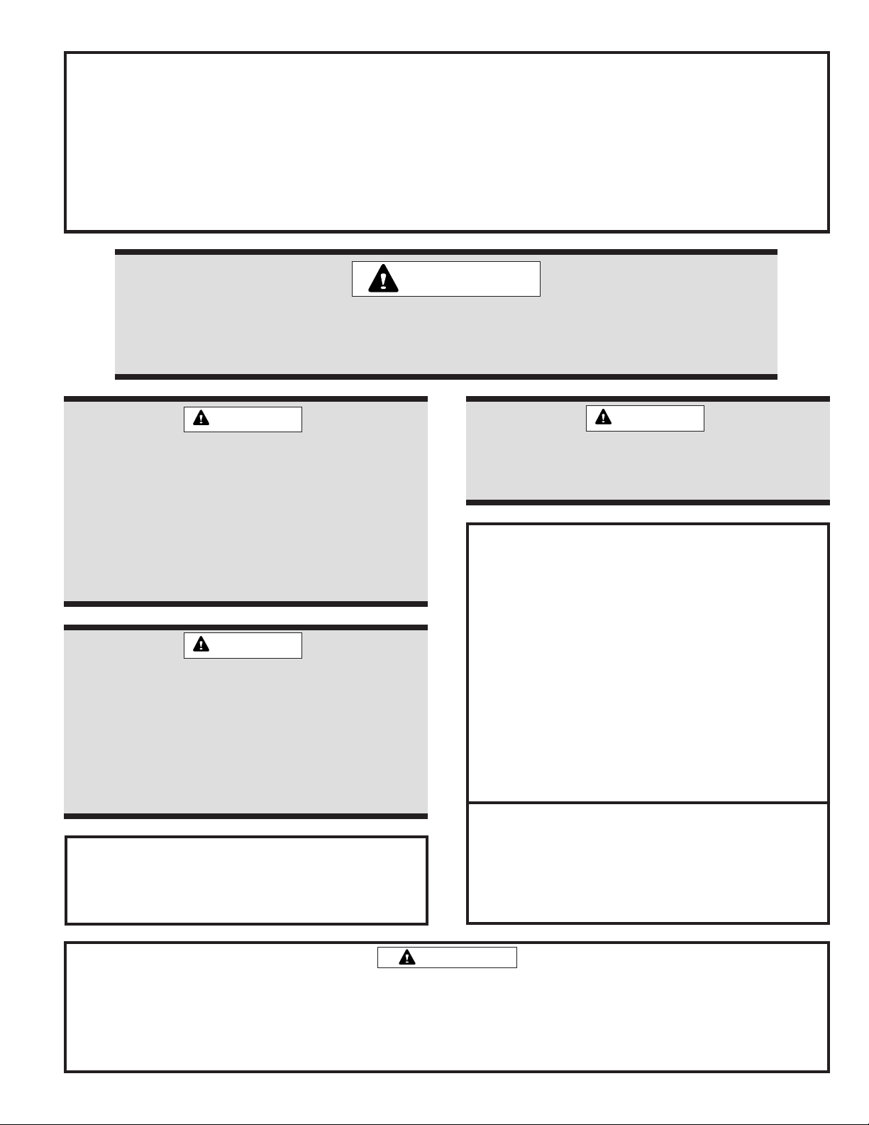
Exercise care when moving the unit. Do not remove any
packaging until the unit is near the place of installation. An
accessory lift kit can be purchased to aid in rigging (see
Figure 1). Spreaders whose length exceed the largest
dimension across the unit must be used across the top
of the unit. Recommended spreader length: 3 ton and smaller
package units – 44", 3.5 ton and larger units – 54".
Units may also be moved or lifted with a forklift while still
in the factory-supplied packaging. The lengths of the
forks of the forklift must be a minimum of 42".
CAUTION
Before lifting a unit, make sure that the weight
is distributed equally on the cables so that it
will lift evenly.
Page 2 # 48369K005
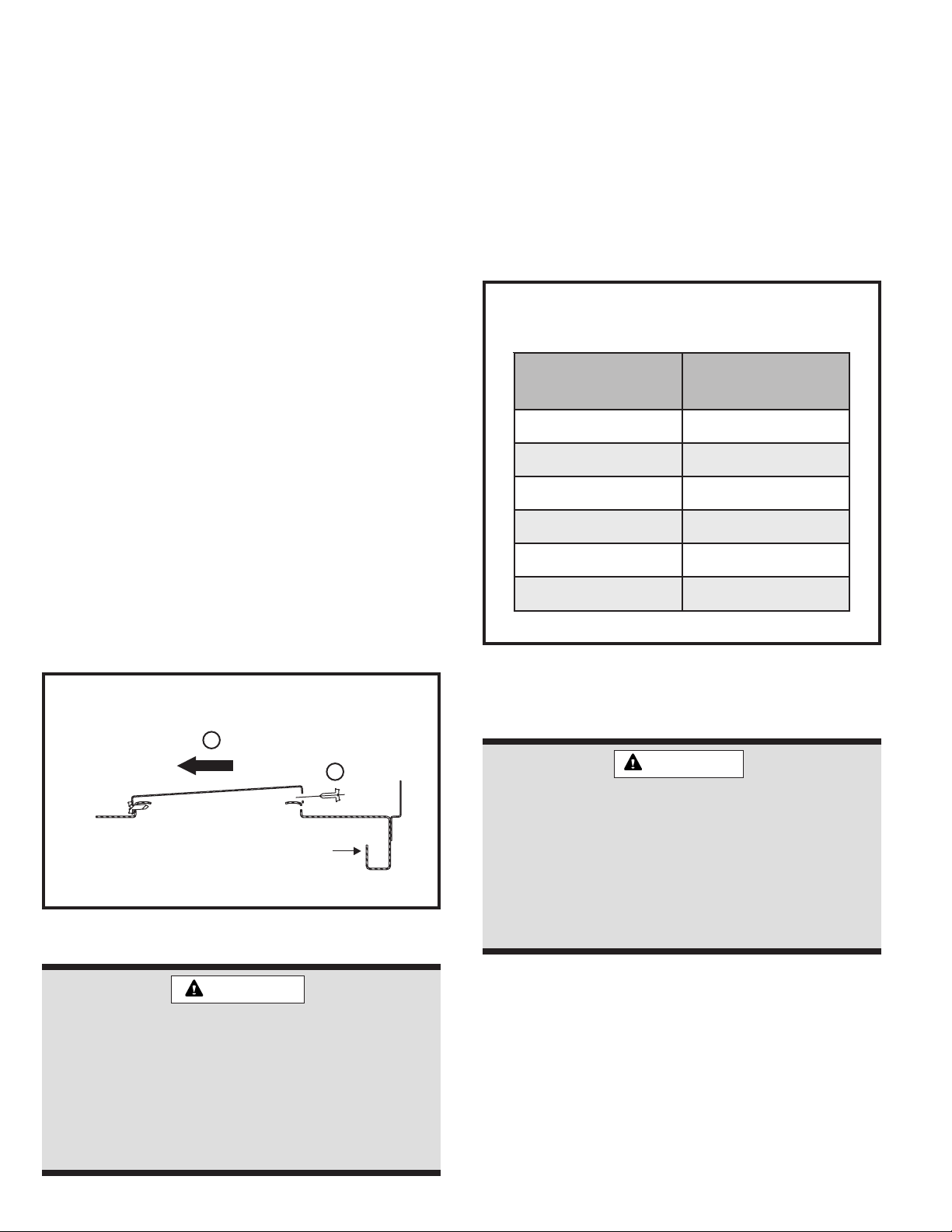
Unit
Drain Connection
Positive Liquid Seal Required
3.00" Min.
1.00" Min.
12.00"
Max.
Using Accessory Lift Kit
Minimum Clearance Requirements
Lifting Bracket
Spreaders
(Field Supplied)
Accessory
Sheet Metal
Screw
To avoid possible
damage to unit
panels from lifting
clevis, place
packing material
between clevis
and panels before
lifting unit.
Figure 1
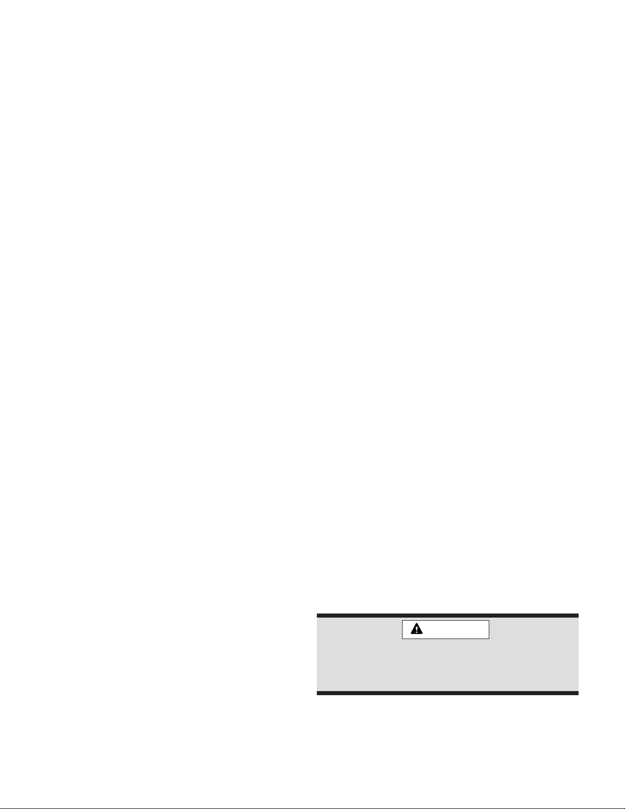
Roof Curb Installation
If a roof curb is used, follow the manufacturer’s Installation
Instructions and be sure that all required clearances are
observed (see following Clearances section).
Roof Curb Assembly
oT
elbitsubmoC
lairetaM
tnorF"0"84"3
raeR "0 "42 "3
resnednoC
dnE
rewolB
dnE
poT"0"63"63
"0"42"3
"0 "03 "0
roF
ecivreS
roF
reporP
noitarepO
Table 1
Condensate Drain
The SH package unit is equipped with a 3/4" FPT coupling for condensate line connection. Plumbing must
conform to local codes. Use a sealing compound on male
pipe threads.
The condensate drain line must be properly trapped
and routed to a suitable drain. See Figure 3 for proper
drain arrangement. The drain line must pitch to an open
drain or pump to prevent clogging of the line. Seal around
the drain connection with suitable material to prevent air
leakage into the return air system.
Figure 2
Typical Condensate Drain Connection
Clearances
All units require certain clearances for proper operation and
service. Refer to Table 1 for the minimum clearances to
combustibles as well as minimum clearances necessary
for servicing and proper unit operation.
In the U.S., units may be installed on combustible floors
made from wood or class A, B, or C roof covering material.
In Canada, units may be installed on combustible floors.
Service Access
Access to all serviceable components is provided by four
removable panels: filter compartment, blower compartment, heater compartment, and top panel.
# 48369K005 Page 3
Figure 3
Ductwork
Filters
Ductwork should be designed and sized according to the
methods in Manual Q of the Air Conditioning Contractors of
America (ACCA).
A closed return duct system shall be used. This shall not
preclude use of economizers or outdoor fresh air intake. It
is recommended that supply and return duct connections
at the unit be made with flexible joints.
The supply and return air duct systems should be designed for the CFM and static requirements of the job.
They should not be sized by matching the dimensions
of the duct connections on the unit.
Outdoor ductwork must be insulated and waterproofed.
Equipment is shipped for side ductwork connection. The
unit can be converted to bottom ductwork connection by
removing the duct covers located over the bottom duct
openings and placing these covers over the side duct
openings (see Figure 4).
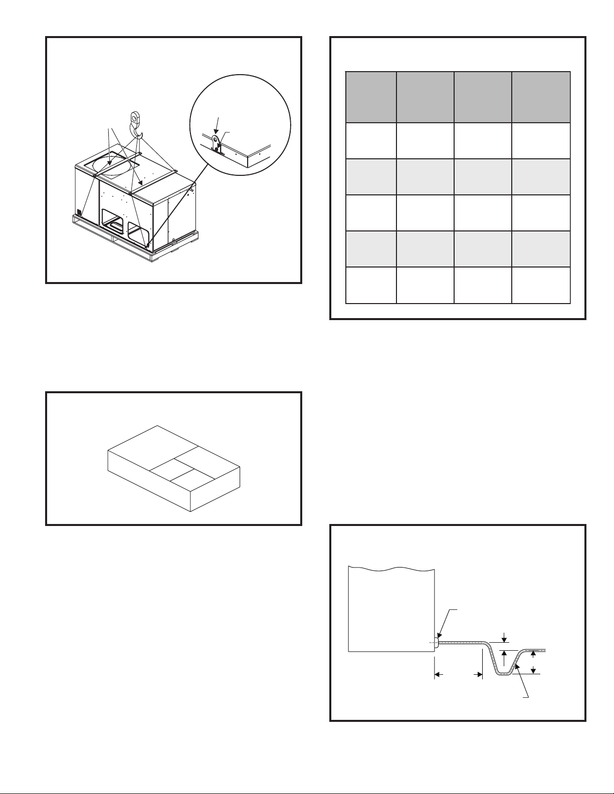
To remove the bottom duct cover over supply opening:
1. Remove screw on cover nearest side opening.
2. Lift end of cover slightly and push to slide back screw/
pin free from duct flange.
Air filters are to be used with this heating/cooling unit.
Filters are not factory supplied in the unit. However, a filter
frame accessory is available from the manufacturer that
allows filters to be installed within the unit. If the filter
frame accessory is not used, a filter must be installed in
the duct work by the installer. Filters must always be
installed ahead of the evaporator coil and must be kept
clean or replaced. Dirty filters will reduce the airflow of the
unit. Filters should be sized in accordance with Table 2.
Minimum Required Surface Area
for Disposable Filters
gnilooClanimoN
000,4276.2
000,03 33.3
000,6300.4
000,24 76.4
000,8433.5
000,06 76.6
aerAretliF
).tf.qs(
3. Slide duct cover out the side duct opening.
Removing Bottom Duct Covers
2
1
1. Remove screw and lift.
2. Slide cover to free back pin.
Base
Figure 4
CAUTION
When fastening ductwork to side duct flanges
on unit, insert screws through duct flanges
only; do not insert screws through casing. If
using bottom duct work, do not use screws to
secure ductwork to bottom duct opening
under drain pan side. Using screws to secure
bottom duct may damage drain pan.
Table 2
Electrical Wiring
WARNING
Line voltage is present at all components when
unit is not in operation on units with single pole
contactors. Disconnect all remote electric
power supplies before opening access panel.
Unit may have multiple power supplies. Failure
to disconnect all power supplies could result in
personal injury or death.
All wiring should be done in accordance with the
National Electrical Code, ANSI/NFPA No. 70 (latest
edition); Canadian Electrical Code Part 1, CSA C22.1
(latest edition); or local codes where they prevail. Use
wiring with a temperature limitation of 75°C minimum. Run
the 208 or 230 volt, 60 hertz electric power supply through
a fused disconnect switch to the connection box of the unit
and connect as shown in the wiring diagram located on the
inside of the control access panel.
Page 4 # 48369K005
 Loading...