

Ducane (HVAC) 2HP13-14 User Manual
2HP13/14 & 4HP13 SPLIT SYSTEM HEAT PUMP
INSTALLATION / START-UP INSTRUCTIONS
/HOMEOWNERS INFORMATION MANUAL
These instructions must be read and understood completely before attempting installation.
TABLE OF CONTENTS
Safety Precautions ..................................... 2
Unit Location & Installation ............................... 2
Rooftop Installation & Recommendations . . . . . . . . . . . . . . . . . . . . 3
Indoor Coil Piston Selection .............................. 3
Refrigeration Line Sets .................................. 3
Installation of Line Sets .................................. 4
Leak Check ........................................... 4
Evacuating & Charging .................................. 4
Opening Service Valve .................................. 5
Electrical Connections................................... 5
Control Wiring ......................................... 5
Start-Up Procedure ..................................... 6
Adjusting charge ....................................... 6
Defrost System ........................................ 7
Single Phase Wiring Diagram ............................. 9
3 Phase Wiring Diagram ................................. 10
Homeowner's Information ................................ 11
These units are designed for use in residential and light commercial type buildings. Heat Pumps may only be
installed with indoor combinations listed in the Air-Conditioning and Refrigeration Institute (ARI) Directory of
Certified Products.
Inspect the unit for any damage before installation. If damage is found, notify the transportation company
immediately and file a concealed damage claim.
Installation or repairs made by unqualified persons can result in hazards to you and others. Installation
MUST conform with local building codes and with the National Electrical Code NFPA 70/ANSI C1-1993 or
current edition and Canadian Electrical Code Part 1 CSA C22.1.
Improper installation, adjustment, alteration, service or maintenance will void the warranty. The qualified installer or
agency must use factory-authorized kits or accessories when added to this products. Refer to the individual instructions
included with the specific accessory kit.
NOTE
These instructions are intended as a general guide and do not supersede national, state or local codes in any way.
These instructions must be left with the property owner.
506162-02 Issue 0847 Page 1 of 14
NOTE TO INSTALLING DEALER
These instructions and warranty are to be given
to the owner or prominently displayed near the
indoor air handler unit.
UNIT LOCATION & INSTALLATION
NOTE: In some cases noise in the living area has been
traced to gas pulsations from improper installation
of equipment.
1. Locate unit away form windows, patios, decks, etc.
where unit operation sounds may disturb customer.
This product and/or the indoor unit that is matched
with may contain fiberglass wool.
Disturbing the insulation during installation,
maintenance, or repair will expose you to fiberglass
wool dust. (Fiberglass wool is known to the State of
California to cause cancer.)
Fiberglass wool may also cause respiratory, skin,
and eye irritation.
To reduce exposure to this substance or for further
inform ation, consult material safety data sheets
available from your distributor.
Before installing, modifying, or servicing system,
main electrical disconnect switch must be in the OFF
position. There may be more than 1 disconnect
switch. Lock out and tag switch with a suitable
warning label. Electrical shock can cause personal
injury or death.
2. Ensure that vapor and liquid tube diameters are
appropriate to capacity of unit.
3. Run refrigerant tubes as directly as possible by
avoiding unnecessary turns and bends.
4. Leave some slack between structure and unit to
absorb vibration.
5. When passing refrigerant tubes through the wall, seal
opening with RTV or other silicon-based caulk.
6. Avoid direct tubing contact with water pipes, duct work,
floor joists, wall studs, floors, walls, and any structure.
7. Do not suspend refrigerant tubing from joists and studs
with a rigid wire or strap which comes in direct contact
with tubing.
8. Ensure that tubing insulation is pliable and completely
surrounds vapor tube.
When outdoor unit is connected to factory-approved
indoor unit, outdoor unit contains system refrigerant charge
for operation with indoor unit of the same size when
connected by 15 ft. of field-supplied tubing. For proper unit
operation, check refrigerant charge using charging
information located on control box cover.
IMPORTANT: Maximum liquid-line size is 3/8 in. O.D. for
all residential applications including long
Safety Precautions
Follow all safety codes. Wear safety glasses and work
gloves. Use quenching cloth for brazing operations. Have
fire extinguisher available. Read these instructions
thoroughly and follow all warning or cautions attached to
the unit.
1. Always wear proper personal protection equipment.
2. Always disconnect electrical power before removing
panel or servicing equipment.
3. Keep hands and clothing away from moving parts.
4. Handle refrigerant with caution, refer to proper MSDS
from refrigerant supplier.
5. Use care when lifting, avoid contact with sharp edges.
506162-02 Issue 0847 Page 2 of 14
Outdoor Section
Zoning ordinances may govern the minimum distance
the condensing unit can be installed from the property line.
Install on a Solid, Level Mounting Pad
The outdoor section is to be installed on a solid
foundation. This foundation should extend a minimum of
2" (inches) beyond the sides of the outdoor section. To
reduce the possibility of noise transmission, the foundation
slab should NOT be in contact with or be an integral part of
the building foundation.
lines.
Elevate Unit
Accumulation of water and ice in base pan may
cause equipment damage.
DO LOCATE THE UNIT:
! W ith proper clearances on sides and top of unit
! On a solid, level foundation or pad
! To minimize refrigerant line lengths
Elevate unit per local climate and code requirem ents to
provide clearance above estim ated snowfall level and
ensure adequate drainage of unit. Use snow stand in
areas where prolonged freezing temperatures are
encountered.
If conditions or local codes require the unit be attached
to pad or mounting frame, tie down bolts should be used
and fastened through knockouts provided in unit base pan.
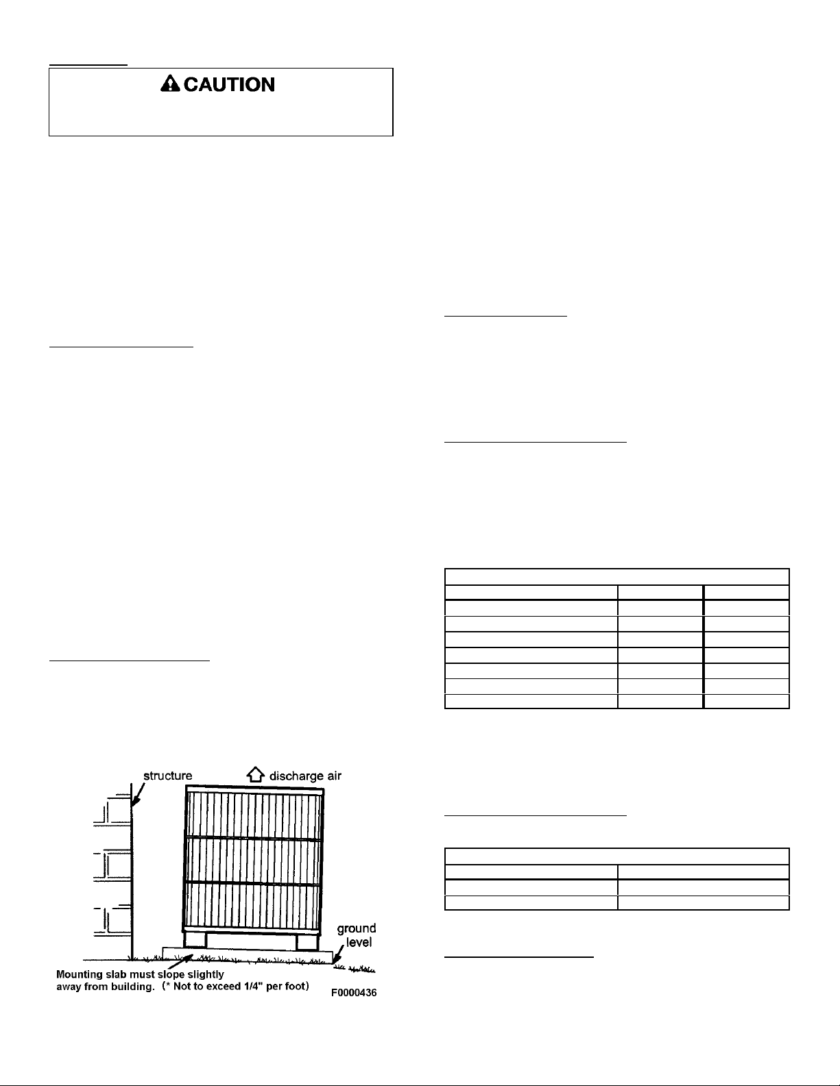
Roof Top Installations
Mount on level platform or frame 6 inches above roof
surface. Place unit above a load-bearing wall and isolate
unit and tubing set from structure. Arrange supporting
members to adequately support unit and m inimize
transmission of vibration to building. Ensure roof structure
and anchoring method is adequate for location. Consult
local codes governing rooftop applications.
Roof mounted units exposed to winds above 5 mph
may require wind baffles to achieve adequate defrost. A
sheet metal baffle should be spaced 6-1/2" from the fall of
the coil. The height should cover the face of the coil and
the length should be 6" from the access panel.
NOTE: Unit must be level to within ± 2/ (± 3/8 in./ft) per
compressor manufacturer specifications.
Clearance Requirements
When installing, allow sufficient space for airflow
clearance, wiring, refrigerant piping, and service. For
proper airflow, quiet operation and maxim um efficiency.
Position so water, snow, or ice from roof or eaves cannot
fall directly on unit.
DO NOT LOCATE THE UNIT:
! On brick, concrete blocks or unstable surfaces
! Near clothes dryer exhaust vents
! Near sleeping area or near windows
! Under eaves where water, snow or ice can fall
directly on the unit
! w ith clearance less than 2 ft. from a second unit
! w ith clearance less than 4 ft. on top of unit
Operating Ambient
The minimum outdoor operating ambient in cooling
mode is 55/F, and the maximum outdoor operating
ambient in cooling mode is 125/F. The maximum outdoor
operating ambient in heating mode is 66/F.
Indoor Coil Piston Selection
The outdoor heat pump section must be matched to a
factory approved indoor section. It is mandatory that the
installer ensure that the correct piston is installed in the
indoor section. If necessary remove the existing piston and
replace it with the correct piston See indoor unit
instructions for details of changing the piston. Contact
your distributor for accessory piston kits.
Indoor (Cooling) Piston Size
13 SEER Heat Pump Indoor Piston Sizes
Unit Size 2HP13 4HP13
18 .055 .051
24 .063 .055
30 .068 .059
36 .076 .070
42 .076 .070
48 .082 .082
60 .098 .082
The evaporator coil may use an expansion valve (TXV) in place of piston.
NOTE: If a TXV is installed a hard start kit is required on
all models with reciprocating compressors. See spec
sheet for proper kit selection.
14 SEER Heat Pum p Models
All 14 SEER heat pump models are only rated with TXV on
the indoor side.
14 SEER Heat Pump Indoor TXV
Unit Size TX V Kit
18 thru 36 TXV3
42 thru 48 TXV5
Refrigeration Line Sets
Use only refrigerant grade copper tubes. Split
systems may be installed with up to 50 feet of line set (no
more than 20 feet vertical) without special consideration
(see long line set guidelines).
506162-02 Issue 0847 Page 3 of 14
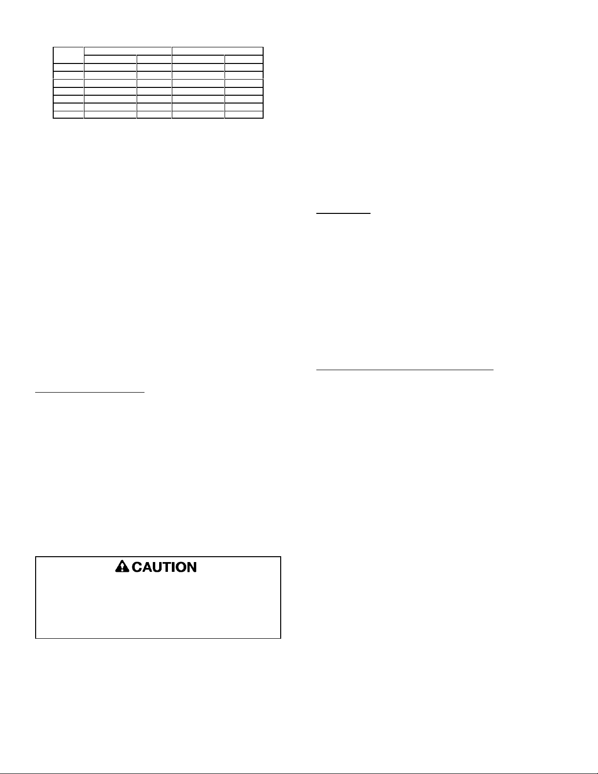
Recommended Liquid & Vapor Tube Diameters (In.)
Unit
Size
Connection Dia. Tube Dia. Connection Dia. Tube Dia.
018 3/8" 3 /8" 3/4 3/4
024 3/8" 3 /8" 3/4 3/4
030 3/8" 3 /8" 3/4 3/4
036 3/8" 3 /8" 3 /4 3/4
042 3/8" 3 /8" 7/8 7/8
048 3/8" 3 /8" 7/8 7/8
060 3/8" 3 /8" 7/8 *1-1/8
*FIELD SUPPLIED 7/8 X 1-1/8 CONNECTOR REQUIRED ON BOTH
ENDS OF VAPOR TUBING.
LIQUID VAPOR
It is important that no tubing be cut or seals broken
until you are ready to actually make connections to the
evaporator and to the condenser section. DO NOT remove
rubber plugs or copper caps from the tube ends until ready
to make connections at evaporator and condenser. Under
no circumstances leave the lines open to the atmosphere
for any period of time, if so unit requires additional
evacuation to remove moisture.
Be extra careful with sharp bends. Tubing can "kink"
very easily, and if this occurs, the entire tube length will
have to be replaced. Extra care at this time will eliminate
future service problems.
It is recommended that vertical suction risers not be
up-sized. Proper oil return to the compressor should be
maintained with suction gas velocity.
The following is the recommended method for making
braze connections at the refrigerant line connections:
1. Debur and clean refrigerant tube end with emery
cloth or steel brush.
2. Insert tubing into swage fitting connection.
3. W rap wet rags over valves to protect from heat.
4. Allow dry nitrogen to flow through refrigerant lines.
5. Braze joint, using a suitable brazing alloy for copper
to copper joints.
6. Quench the joint and tubing with water using a wet
rag. Leave rag on fitting body and re-wet with water
to help cool area.
Leak Check
Refrigeration lines and indoor coil must be checked for
leaks after brazing and before evacuation. The
recommended procedure is to apply a trace amount of
vapor refrigerant (approximately two ounces or 3 psig) into
the line set and indoor coil, then pressurize with 150 psig
of dry nitrogen. Use a refrigerant leak detector to check all
joints. The system may also be checked for leaks using a
halide torch or pressure and soapy solution. After
completion of leak check, relieve all pressure from system
before evacuation.
Installation of Line Sets
DO NOT fasten liquid or suction lines in direct contact
with the floor or ceiling joist. Use an insulated or
suspension type of hanger. Keep both lines separate, and
always insulate the suction line. Long liquid line runs (30
feet or more) in an attic will require insulation. Route
refrigeration line sets to minimize length.
DO NOT let refrigerant lines come in direct contact with
foundation. When running refrigerant lines through the
foundation or wall, openings should allow for a sound and
vibration absorbing material to be placed or installed
between tubing and foundation. Any gap between
foundation or wall and refrigerant lines should be filled with
a vibration damping m aterial.
If ANY refrigerant tubing is buried, provide a 6 inch
vertical rise at service valve. Refrigerant tubing
lengths up to 36 inches may be buried without further
special consideration. For lengths above 36 inches,
consult your local distributor.
Before making braze connections, be sure all joints are
clean. Before heat is applied for brazing, dry nitrogen
should be flowing through the tubing to prevent oxidation
and scale formation on the inside of the tubing.
Evacuating And Charging Instructions
NOTE: Intentional release of CFC or HCFC refrigerant
to the atmosphere violates Federal Law. It may
also violate State and Local Codes. Check all
Federal, State and Local Codes before
proceeding.
These outdoor units are pre-charged at the factory with
adequate refrigerant to handle 15 feet of refrigerant tubing.
NOTE: DO NOT use any portion of the charge for purging
or leak testing. It is mandatory that a thorough
evacuation of the refrigeration lines and indoor coil
be performed.
The liquid line and suction line service valves have been
closed after final testing at the factory. DO NOT disturb
these valves until the lines have been leak checked and
evacuated or the charge in the unit may be lost.
1. Connect the vacuum pump to the center hose of the
manifold gauge set, the low-pressure m anifold
gauge to the vapor service valve and the high
pressure manifold gauge to the liquid service valve.
NOTE: Unnecessary switching of hoses can be avoided
and complete evacuation of all lines can be
achieved by also connecting a branch hose from
the manifold gauge center port to a cylinder of the
proper refrigerant. Provide a separate shut-off
valve to vacuum pump to avoid contaminating
vacuum pump oil with refrigerant.
506162-02 Issue 0847 Page 4 of 14
2. The valves should be kept in the "front seated"
(closed) position. This will allow evacuation of the
refrigeration lines and the indoor coil, without
disturbing the factory charge in the outdoor unit.
3. Follow the vacuum pump manufacturer's
instructions. Allow the pump to operate until the
system has been evacuated down to 300 microns.
Allow the pump to continue running for an additional
15 minutes. Turn OFF the pump and leave the
connections secured to the two (2) service valves.
After 5 minutes, if the system fails to hold 500
microns or less, check all connections for tight fit and
repeat the evacuation procedure.
4. Isolate the vacuum pump from the system by closing
the shutoff valves on the gauge-set. Disconnect the
vacuum pump.
Opening Service Valves
After evacuation of the connecting lines, remove the
service valve cap and fully insert the hex wrench into the
stem . A back-up wrench is required on the valve body to
open the valve stem. Back-out counterclockwise until the
valve stem just touches the coined edge.
Wrench sizes:
3/8 service valve: 3/16" Hex wrench
3/4 service valve: 5/16" Hex wrench
7/8 service valve: 5/16" Hex wrench
Replace service valve cap and torque to 8-11 ft-lb on 3/8"
valves; 12-15 ft-lb on 3/4" valves; 15-20 ft-lb on 7/8" valves.
Use backup wrench on valve body when torqueing valve
cap.
Provide line voltage power supply to unit from a properly
sized disconnect switch. Route power and ground wires
from disconnect switch to unit. Line voltage connections
are made at the line side of the contactor in the control box
of the outdoor unit. Follow the appropriate wiring diagram
attached to inside of the access panel.
Proper circuit protection recomm endations are indicated
on Unit Rating Plate. Time delay fuses are required to
prevent blowing due to starting current (the current in rush
when equipment starts is referred to as the Locked Rotor
Amps or (LRA). A fuse of this kind properly sized will give
maximum equipment protection.
Use copper wire only between disconnect switch and
unit.
Remove access panel to gain access to unit wiring.
Extend wires from disconnect through power wiring hole
provided and into unit control box. Flexible conduit is
required for the swing out control box feature.
The unit cabinet must have an uninterrupted or
unbroken ground to minimize personal injury if an
electrical fault should occur. The ground may consist
of electrical wire or metal conduit when installed in
accordance with existing electrical codes. Failure to
follow this warning can result in an electric shock,
fire, or death.
Connect ground wire to ground connection in control box
for safety. Connect power wiring to contactor.
Install Electrical Accessories
Refer to the instructions packaged with the accessories.
Electrical Connections
....
ELECTRICAL SHOCK HAZARD!
Turn OFF electric power before connecting unit,
performing any maintenance or removing
panels or doors. More than one disconnect
may be required to turn off all power.
FAILURE TO DO SO COULD RESULT IN BODILY
INJURY OR DEATH.
Be sure to check all local codes to determine that the unit
is installed accordance with local requirements. Consult
the National Electric Code for wire size requirements. Use
60/ C wire or higher. Always provide ground connections
to the outdoor unit. Power supply m ust agree with rating
on unit nameplate.
High voltage power connections to 3-phase m odels is
made to "Pig Tail" leads with field supplied splice
connectors.
Control Wiring
The control voltage is 24 Vac. NEC Class I insulated 18
AWG is required for control wiring. For lengths longer than
150 feet, contact your local distributor for technical service.
Ensure the room thermostat is properly installed per
instructions shipped with room thermostat. Generally the
thermostat should not be exposed to sunlight, drafts or
vibration and should not be mounted on exterior walls.
Low voltage control wire connections should be made to
the screw connection terminal board mounted on the
defrost control as shown. All low voltage control wiring
must be separated from incoming power leads.
506162-02 Issue 0847 Page 5 of 14
 Loading...