

Page 1
INSTALLATION INSTRUCTIONS
Warm Air Gas Furnace
Downow Air Discharge
97G2DFV
This manual must be left with the homeowner for future reference.
This is a safety alert symbol and should never be ignored. When you see this symbol on labels or in manuals, be alert to
the potential for personal injury or death.
Direct Vent & Non-Direct Vent
Table of Contents
Unit Dimensions ........................................................ 2
WARNING
Improper installation, adjustment, alteration, service
or maintenance can cause property damage, personal
injury or loss of life. Installation and service must be
performed by a licensed professional installer (or
equivalent), service agency or the gas supplier.
CAUTION
As with any mechanical equipment, personal injury can
result from contact with sharp sheet metal edges. Be
careful when you handle this equipment.
Parts Arrangement..................................................... 3
Gas Furnace .............................................................. 4
Shipping and Packing List ......................................... 4
Safety Information ..................................................... 4
General ...................................................................... 6
Combustion, Dilution & Ventilation Air ....................... 7
Installation ............................................................... 10
Filters ....................................................................... 12
Duct System ............................................................ 12
Venting Practices ..................................................... 15
Condensate Piping .................................................. 31
Gas Piping ............................................................... 34
Electrical .................................................................. 36
Testing for Proper Venting and Sucient Combustion
Air for Non-Direct Vent Applications ........................ 44
Unit Start-Up ............................................................ 45
Blower Performance ................................................ 48
Service..................................................................... 50
Planned Service ...................................................... 52
Repair Parts List ...................................................... 52
Manufactured By
Allied Air Enterprises LLC
A Lennox International, Inc. Company
215 Metropolitan Drive
West Columbia, SC 29170
508405-01 Page 1 of 53Issue 2332
*P508405-01*
(P) 508405-01
Page 2
9/16
(14)
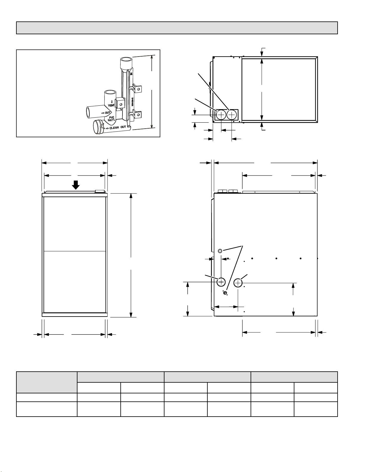
Unit Dimensions
9/16
(14)
Flue Condensate Trap Assembly
Furnished for external
field installation
on either side of unit.
(See installation instructions
for additional
information.)
A
B
AIR
FLOW
9/16
(14)
33
(838)
COMBUSTION
AIR INTAKE
7
(178)
EXHAUST AIR
GAS PIPING INLET
(Either Side)
9-1/8 (232) Right
6-9/16 (167) Left
OUTLET
2-1/16 (52)
1 (25)
Front Panel
2 (51)
Either Side
5
(127)
RETURN AIR
B
OPENING
2-1/4
(57)
9/16
(14)
TOP VIEW
27-3/4
(705)
19-7/16
(494)
ELECTRICAL INLET
(Either Side)
CONDENSATE
TRAP CONNECTION
(Either Side)
6-7/16 (163)
Either Side
9 (229)
Either Side
3/4
(19)
C
Supply
Air
3/4
(19)
19-1/4
(489)
Supply
FRONT VIEW SIDE VIEW
Capacity
070-16 17-1/2 446 16-3/8 416 16 406
090-20
110-20
in. mm in. mm in. mm
21 533 19-7/8 504 19-1/2 495
A B C
Air
3/4
(19)
508405-01Page 2 of 53 Issue 2332
Page 3
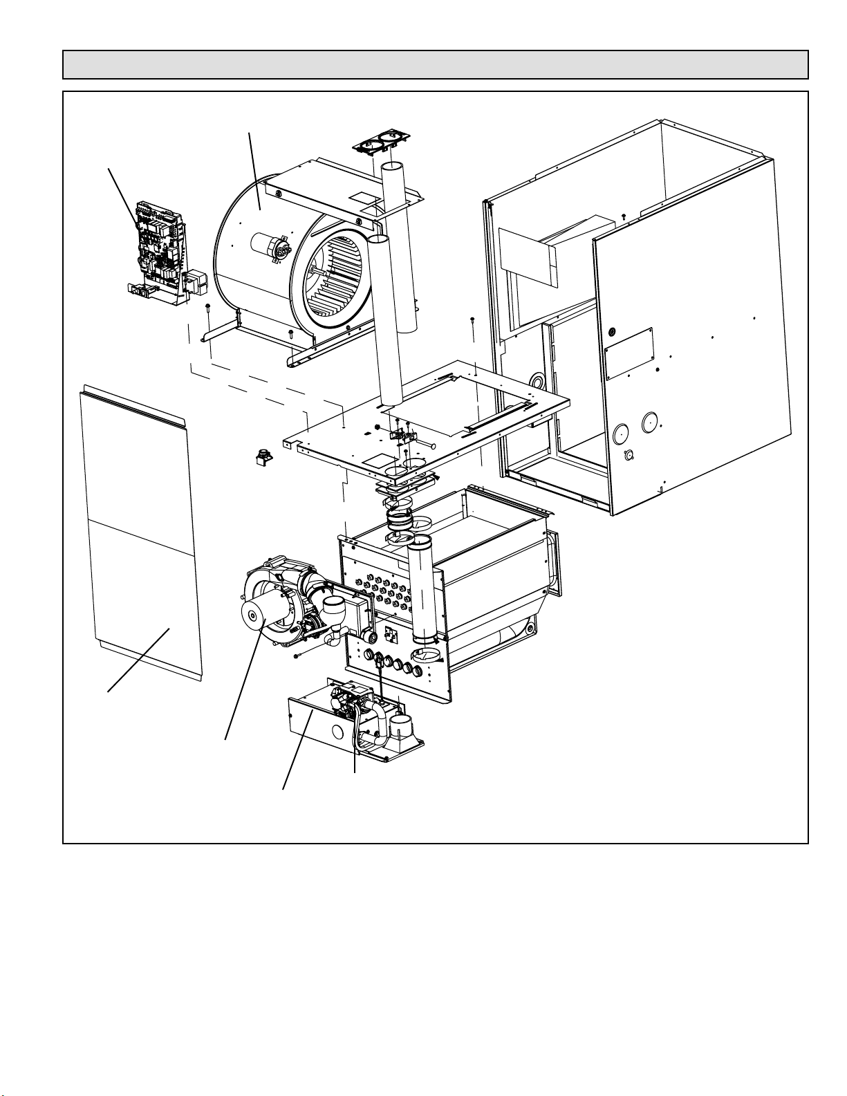
Parts Arrangement
Blower Assembly
Control Box
Access Panel
Combustion Air
Inducer
Gas Valve
Burner Box
Assembly
Figure 1.
508405-01 Page 3 of 53Issue 2332
Page 4
Gas Furnace
Shipping and Packing List
This Category IV gas furnace is shipped ready for
installation in the downow position.
The furnace is equipped for installation in natural gas
applications. A conversion kit (ordered separately) is
required for use in LP/propane gas applications.
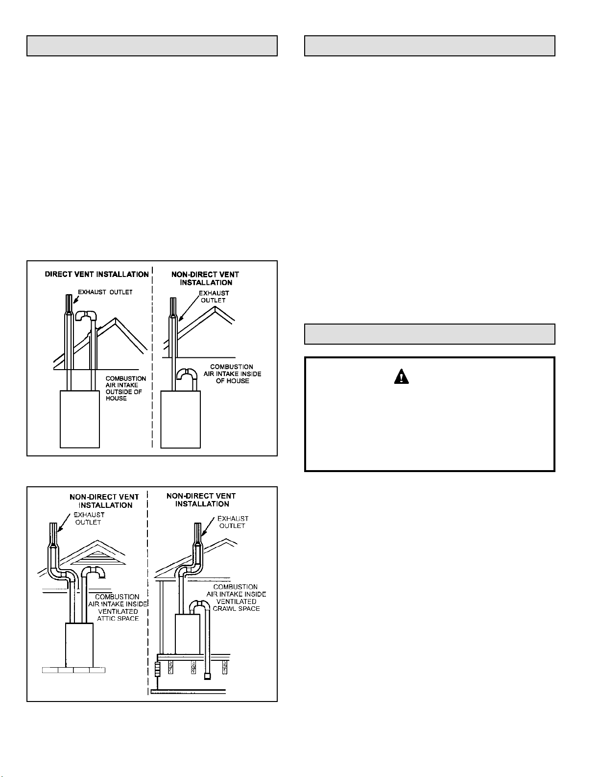
This unit can be installed as either a Direct Vent or a NonDirect Vent gas central furnace.
NOTE: In Direct Vent installations, combustion air is taken
from outdoors and ue gases are discharged outdoors.
Non-Direct Vent installations, combustion air is taken from
indoors or ventilated attic or crawl space and ue gases
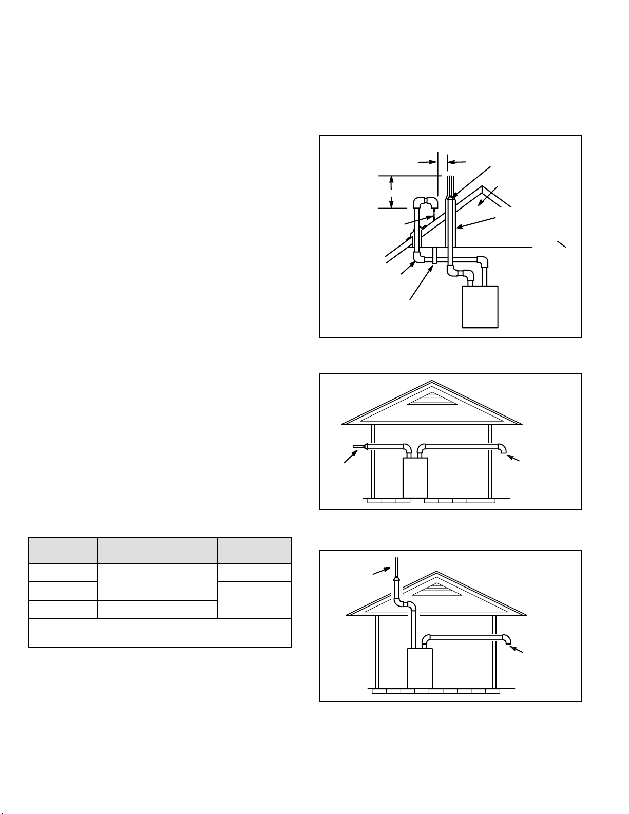
are discharged outdoors. See Figure 2 and Figure 3 for
application involving roof termination.
Package 1 of 1 contains:
1 - Assembled Gas Unit
1 - Bag assembly containing the following:
1 - Snap bushing
1 - Snap Plug
1 - Wire tie
1 - Condensate trap
1 - Condensate trap cap
1 - Condensate trap clamp
1 - 2” diameter debris screen
1 - 3/4” Threaded street elbow
Check equipment for shipping damage. If you nd any
damage, immediately contact the last carrier.
Please refer to specication sheets for available
accessories.
Safety Information
Figure 2.
DANGER
DANGER OF EXPLOSION!
There are circumstances in which odorant used with
LP/propane gas can lose its scent. In case of a leak,
LP/propane gas will settle close to the oor and may be
dicult to smell. An LP/propane leak detector should be
installed in all LP applications.
Use only the type of gas approved for use with this furnace.
Refer to unit nameplate.
This unit is CSA International certied to ANSI Z21.47 and
CSA 2.3 standards.
Building Codes
In the USA, installation of gas furnaces must conform with
local building codes. In the absence of local codes, units
must be installed according to the current National Fuel
Gas Code (ANSI Z223.1/NFPA 54). The National Fuel Gas
Code is available from the American National Standards
Institute, Inc., 11 West 42nd Street, New York, NY 10036.
In Canada, installation must conform with current National
Standard of Canada CSA-B149 Natural Gas and Propane
Installation Codes, local plumbing or waste water codes
and other applicable local codes.
Figure 3.
In order to ensure proper unit operation in non-direct vent
applications, combustion and ventilation air supply must
508405-01Page 4 of 53 Issue 2332
Page 5

be provided according to the current National Fuel Gas
Code or CSA-B149 standard.
Locations and Clearances
This furnace is CSA International certied for installation
clearances to combustible material as listed on the unit
nameplate and in the table in Figure 14. Accessibility
and service clearances must take precedence over re
protection clearances.
NOTE: When furnace is installed on a combustible oor,
a downow combustible ooring base must be installed
between the furnace and the oor.
For installation in a residential garage, the furnace must be
installed so that the burner(s) and the ignition source are
located no less than 18 inches (457 mm) above the oor.
The furnace must be located or protected to avoid physical
damage by vehicles. When a furnace is installed in a public
garage, hangar, or other building that has a hazardous
atmosphere, the furnace must be installed according to
recommended good practice requirements and current
National Fuel Gas Code or CSA B149 standards.
NOTE: Furnace must be adjusted to obtain a temperature
rise within the range specied on the unit nameplate.
Failure to do so may cause erratic limit operation and
premature heat exchanger failure.
This gas furnace must be installed so that its electrical
components are protected from water.
Figure 4.
In Canada, all electrical wiring and grounding for the unit
must be installed according to the current regulations of
the Canadian Electrical Code Part I (CSA Standard C22.1)
and/or local codes.
NOTE: This furnace is designed for a minimum continuous
return air temperature of 60°F (16°C) or an intermittent
operation down to 55°F (13°C) dry bulb for cases where a
night setback thermostat is used. Return air temperature
must not exceed 85°F (29°C) dry bulb.
Installed in Combination with a Cooling Coil
When this furnace is used with cooling units (Figure 4),
it shall be installed in parallel with, or on the upstream
side of, cooling units to avoid condensation in the heating
compartment. With a parallel ow arrangement, a damper
(or other means to control the ow of air) must adequately
prevent chilled air from entering the furnace. If the damper
is manually operated, it must be equipped to prevent
operation of either the heating or the cooling unit, unless it
is in the full HEAT or COOL setting.
When installed, this furnace must be electrically grounded
according to local codes. In addition, in the United States,
installation must conform with the current National
Electric Code, ANSI/NFPA No. 70. The National Electric
Code (ANSI/NFPA No. 70) is available from the following
address:
National Fire Protection Association
1 Battery March Park
Quincy, MA 02269
This gas furnace may be installed in alcoves, closets,
attics, basements, garages, and utility rooms.
This furnace design has NOT been CSA certied for
installation in mobile homes, recreational vehicles, or
outdoors.
Never use an open ame to test for gas leaks. Check all
connections using a commercially available soap solution
made specically for leak detection.
Use of Furnace as a Construction Heater
Units may be used for heating of buildings or structures
under construction, if the following conditions are met to
ensure proper operation.
DO NOT USE THE UNIT FOR CONSTRUCTION HEAT
UNLESS ALL OF THE FOLLOWING CRITERIA ARE
MET:
a. Furnace must be in its nal location. The vent system
must be permanently installed per these installation
instructions.
b. Furnace must be installed as a two pipe system
and one hundred percent (100%) outdoor air must
be provided for combustion air requirements during
construction.
508405-01 Page 5 of 53Issue 2332
Page 6
c. A room thermostat must control the furnace. The use
of xed jumpers that will provide continuous heating is
prohibited.
d. The input rate and temperature rise must be set per
the furnace rating plate.
e. Supply and Return air ducts must be provided and
sealed to the furnace. Return air must be terminated
outside of the space where furnace is installed.
f. Return air temperature range between 60°F (16°C)
and 80°F (27°C) must be maintained.
g. MERV 11 or greater air lters must be installed in
the system and must be regularly inspected and
maintained (e.g., regular static checks and replaced at
end of life) during construction.
h. Blower and vestibule access panels must be in place
on the furnace at all times.
i. The furnace heat exchanger, components, duct
system, and evaporator coils must be thoroughly
cleaned following nal construction clean−up.
j. Air lters must be replaced upon construction
completion.
k. All furnace operating conditions (including ignition,
input rate, temperature rise and venting) must
be veried in accordance with these installation
instructions.
EQUIPMENT MAY EXPERIENCE PREMATURE
COMPONENT FAILURE AS A RESULT OF FAILURE TO
FOLLOW THE ABOVE INSTALLATION INSTRUCTIONS.
FAILURE TO FOLLOW THE ABOVE INSTALLATION
INSTRUCTIONS VOIDS THE MANUFACTURER’S
EQUIPMENT LIMITED WARRANTY. ALLIED AIR
DISCLAIMS ALL LIABILITY IN CONNECTION WITH
INSTALLER’S FAILURE TO FOLLOW THE ABOVE
INSTALLATION INSTRUCTIONS.
NOTWITHSTANDING THE FOREGOING, INSTALLER
IS RESPONSIBLE FOR CONFIRMING THAT THE USE
OF CONSTRUCTION HEAT IS CONSISTENT WITH
THE POLICIES AND CODES OF ALL REGULATING
ENTITIES. ALL SUCH POLICIES AND CODES MUST BE
ADHERED TO.
General
These instructions are intended as a general guide and do
not supersede local codes in any way. Consult authorities
having jurisdiction before installation.
In addition to the requirements outlined previously, the
following general recommendations must be considered
when installing one of these furnaces:
• Place the furnace as close to the center of the air
distribution system as possible. The furnace should
also be located close to the vent termination point.
• When the furnace is installed in non-direct vent
applications, do not install the furnace where drafts
might blow directly into it. This could cause improper
combustion and unsafe operation.
• When the furnace is installed in a non-direct vent
applications, do not block the furnace combustion air
opening with clothing, boxes, doors, etc. Air is needed
for proper combustion and safe unit operation.
• When the furnace is installed in an attic or other
insulated space, keep insulation away from the
furnace.
• When the furnace is installed in an unconditioned
space, consider provisions required to prevent freezing
of the condensate drain system.
NOTE: The Commonwealth of Massachusetts stipulates
these additional requirements:
• Gas furnaces shall be installed by a licensed plumber
or tter only.
• The gas cock must be “T handle” type.
• When a furnace is installed in an attic, the passageway
to and service area surrounding the equipment shall
be oored.
CAUTION
These units should not be installed in areas normally
subject to freezing temperatures.
508405-01Page 6 of 53 Issue 2332
Page 7
Combustion, Dilution & Ventilation Air
If this unit is installed as a Non-Direct Vent Furnace, follow
the guidelines in this section.
NOTE: In Non-Direct Vent Installations, combustion air is
taken from indoors and ue gases are discharged outdoors.
the National Fuel Gas Code (ANSI-Z223.1/NFPA 54). This
reprinted material is not the complete and ocial position
of ANSI on the referenced subject, which is represented
only by the standard in its entirely.
In Canada, refer to the CSA B149 Installation codes.
CAUTION
WARNING
Insucient combustion air can cause headaches,
nausea, dizziness or asphyxiation. It will also cause
excess water in the heat exchanger resulting in rusting
and premature heat exchanger failure. Excessive
exposure to contaminated combustion air will result
in safety and performance related problems. Avoid
exposure to the following substances in the combustion
air supply:
• Permanent wave solutions
• Chlorinated waxes and cleaners
• Chlorine base swimming pool chemicals
• Water softening chemicals
• De-icing salts or chemicals
• Carbon tetrachloride
• Halogen type refrigerants
• Cleaning solvents (such as perchloroethylene)
• Printing inks, paint removers, varnishes, etc.
• Hydrochloric acid
• Cements and glues
• Antistatic fabric softeners for clothes dryers
• Masonry acid washing materials
In the past, there was no problem in bringing in sucient
outdoor air for combustion. Inltration provided all the air
that was needed. In today’s homes, tight construction
practices make it necessary to bring in air from outside
for combustion. Take into account that exhaust fans,
appliance vents, chimneys, and replaces force additional
air that could be used for combustion out of the house.
Unless outside air is brought into the house for combustion,
negative pressure (outside pressure is greater than inside
pressure) will build to the point that a down draft can
occur in the furnace vent pipe or chimney. As a result,
combustion gases enter the living space creating a
potentially dangerous situation.
In the absence of local codes concerning air for combustion
and ventilation, use the guidelines and procedures in this
section to install these furnaces to ensure ecient and safe
operation. You must consider combustion air needs and
requirements for exhaust vents and gas piping. A portion
of this information has been reprinted with permission from
Do not install the furnace in a corrosive or contaminated
atmosphere. Meet all combustion and ventilation air
requirements, as well as all local codes.
All gas-red appliances require air for the combustion
process. If sucient combustion air is not available,
the furnace or other appliance will operate ineciently
and unsafely. Enough air must be provided to meet the
needs of all fuel-burning appliances and appliances such
as exhaust fans which force air out of the house. When
replaces, exhaust fans, or clothes dryers are used at the
same time as the furnace, much more air is required to
ensure proper combustion and to prevent a down draft.
Insucient air causes incomplete combustion which can
result in carbon monoxide.
In addition to providing combustion air, fresh outdoor air
dilutes contaminants in the indoor air. These contaminants
may include bleaches, adhesives, detergents, solvents
and other contaminants which can corrode furnace
components.
The requirements for providing air for combustion and
ventilation depend largely on whether the furnace is
installed in an unconned or a conned space.
Unconned Space
An unconned space is an area such as a basement
or large equipment room with a volume greater than 50
cubic feet (1.42 m³) per 1,000 Btu (.29 kW) per hour of
the combined input rating of all appliances installed in that
space. This space also includes adjacent rooms which are
not separated by a door. Though an area may appear to
be unconned, it might be necessary to bring in outdoor air
for combustion if the structure does not provide enough air
by inltration. If the furnace is located in a building of tight
construction with weather stripping and caulking around
the windows and doors, follow the procedures in the “Air
from Outside” section.
Conned Space
A conned space is an area with a volume less than 50
cubic feet (1.42 m³) per 1,000 Btu (.29 kW) per hour of
the combined input rating of all appliances installed in that
space. This denition includes furnace closets or small
equipment rooms.
When the furnace is installed so that supply ducts carry
air circulated by the furnace to areas outside the space
508405-01 Page 7 of 53Issue 2332
Page 8
containing the furnace, the return air must be handled by
ducts which are sealed to the furnace casing and which
terminate outside the space containing the furnace. This
is especially important when the furnace is mounted on
a platform in a conned space such as a closet or small
equipment room. Even a small leak around the base of the
unit at the platform or at the return air duct connection can
cause a potentially dangerous negative pressure condition.
Air for combustion and ventilation can be brought into the
conned space either from inside the building or from
outside.
Air from Inside
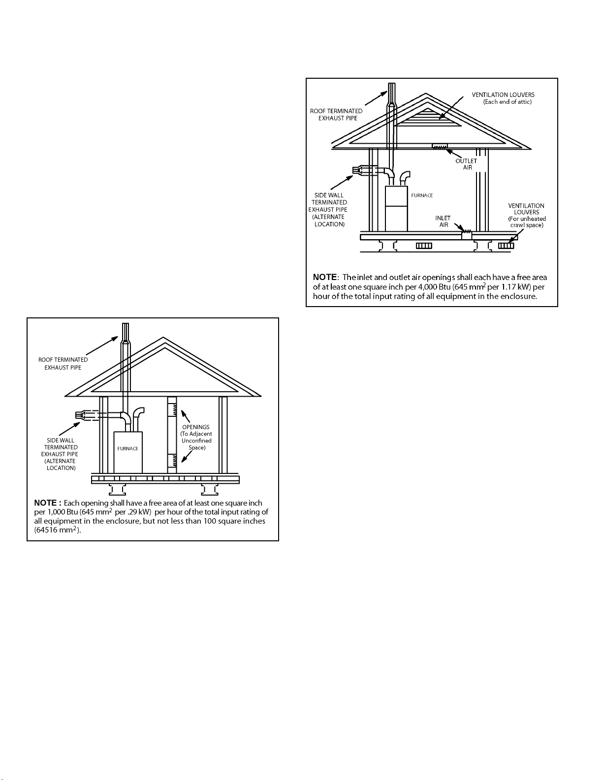
If the conned space that houses the furnace adjoins a
space categorized as unconned, air can be brought in
by providing two permanent openings between the two
spaces. Each opening must have a minimum free area of 1
square inch (645 mm²) per 1,000 Btu (.29 kW) per hour of
total input rating of all gas-red equipment in the conned
space. Each opening must be at least 100 square inches
(64516 mm²). One opening shall be within 12 inches (305
mm) of the top of the enclosure and one opening within 12
inches (305 mm) of the bottom. See Figure 5.
It is also permissible to bring air for combustion from a
ventilated attic (Figure 9) or ventilated crawl space (Figure
10).
Figure 6. Equipment in Conned Space - All Air from
Outside
(Inlet Air from Crawl Space and Outlet Air to
Ventilated Attic)
Figure 5. Equipment in Conned Space - All Air from
Inside
Air from Outside
If air from outside is brought in for combustion and
ventilation, the conned space shall be provided with two
permanent openings. One opening shall be within 12” (305
mm) of the top of the enclosure and one within 12” (305 mm)
of the bottom. These openings must communicate directly
or by ducts with the outdoors or spaces (crawl or attic) that
freely communicate with the outdoors or indirectly through
vertical ducts. Each opening shall have a minimum free
area of 1 square inch per 4,000 Btu (645 mm² per .59 kW)
per hour of the total input rating of all equipment in the
enclosure (see Figure 6 and Figure 7).
When communicating with the outdoors through horizontal
ducts, each opening shall have a minimum free area of 1
square inch (645 mm²) per 2,000 Btu (.56 kW) per hour of
the total input rating of all equipment in the enclosure. See
Figure 8.
When ducts are used, they shall be of the same crosssectional area as the free area of the openings to which
they connect. The minimum dimension of rectangular
air ducts shall be no less than 3 inches (75 mm). In
calculating free area, the blocking eect of louvers, grilles,
or screens must be considered. If the design and free area
of protective covering is not known for calculating the size
opening required, it may be assumed that wood louvers
will have 20 to 25 percent free area and metal louvers and
grilles will have 60 to 75 percent free area. Louvers and
grilles must be xed in the open position or interlocked
with the equipment so that they are opened automatically
during equipment operation.
508405-01Page 8 of 53 Issue 2332
Page 9
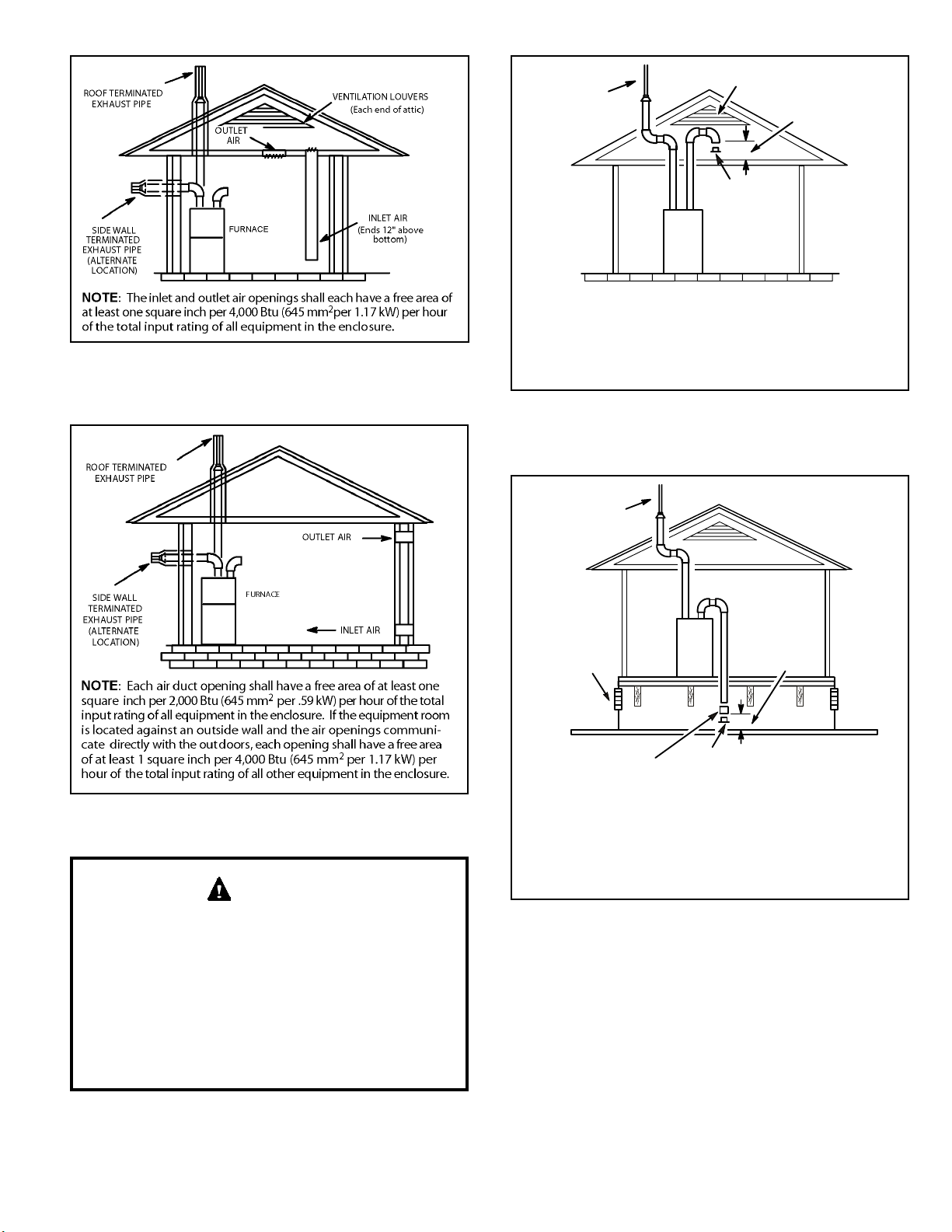
Figure 7. Equipment in Conned Space - All Air from
Outside
(All Air Through Ventilated Attic)
Ventilation Louvers
Roof Terminated
Exhaust Pipe
*Intake Debris
Screen
(Provided)
Furnace
Inlet Air
(Minimum 12 in.
(305mm) above
Attic Floor)
* See Maximum Vent Lengths table
NOTE-The inlet and outlet air openings shall each have a
free area of at least one square inch per 4,000 Btu (645mm2
per 1.17kW) per hour of the total input rating of all equipment
in the enclosure.
Figure 9. Equipment in Conned Space
(Inlet Air from Ventilated Attic and Outlet Air to
Outside)
Roof Terminated
Exhaust Pipe
Figure 8. Equipment in Conned Space - All Air from
Outside
WARNING
If this unit is being installed in an application with
combustion air coming in from a space serviced by an
exhaust fan, power exhaust fan, or other device which
may create a negative pressure in the space, take care
when sizing the inlet air opening. The inlet air opening
must be sized to accommodate the maximum volume
of exhaust air as well as the maximum volume of
combustion air required for all gas appliances serviced
by this space.
Inlet Air
Minimum
Ventilation
Louvers
(Crawl Space)
Coupling or
3 in. to 2 in.
Transition
(Field Provided)
Furnace
12 in. (305mm)
above Crawl
Space Floor
*Intake Debris Screen Provided
* See Maximum Vent Lengths table
NOTE-The inlet and outlet air openings shall each have a
free area of at least one square inch per 4,000 Btu (645mm
per 1.17kW) per hour of the total input rating of all equipment
in the enclosure.
2
Figure 10. Equipment in Conned Space
(Inlet Air from Ventilated Crawl Space and Outlet Air
to Outside)
508405-01 Page 9 of 53Issue 2332
Page 10
Installation
Setting Equipment
WARNING
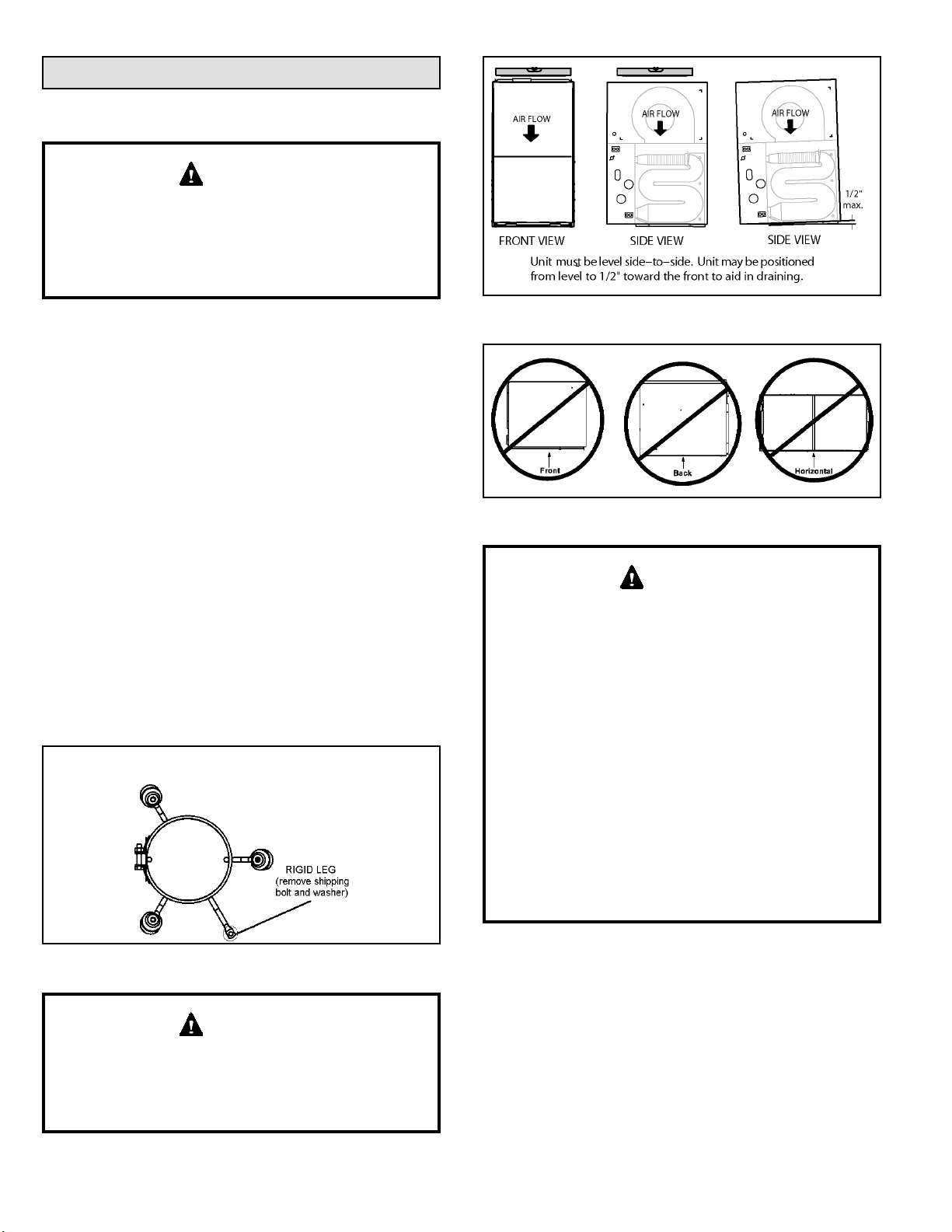
Do not install the furnace on its front, back or in the
horizontal position. See Figure 13. Do no connect the
return air ducts to the back of the furnace. Doing so
will adversely aect the operation of the safety control
devices, which could result in personal injury or death.
Select a location that allows for the required clearances
that are listed on the unit nameplate. Also consider gas
supply connections, electrical supply, vent connection,
condensate trap and drain connections, and installation
and service clearances [24 inches (610 mm) at unit front].
The unit must be level from side to side. Tilt the unit slightly
(maximum 1/2 in. from level) from back to front to aid in the
draining of the heat exchanger. See Figure 12.
Shipping Bolt Removal
NOTE: Units with a 1/2 hp blower motors are equipped
with three exible legs and one rigid leg. The rigid leg
is equipped with a shipping bolt and a at white plastic
washer (rather than the rubber mounting grommet used
with a exible mounting leg). See Figure 11. The bolt and
washer must be removed before the furnace is placed into
operation. After the bolt and washer have been removed,
the rigid leg will not touch the blower housing.
Allow for clearances to combustible materials as indicated
on the unit nameplate. Minimum clearances for closet or
alcove installations are shown in Figure 14.
Units with 1/2 HP Blower Motor
Figure 12. Setting Equipment
Figure 13.
WARNING
Improper installation of the furnace can result in
personal injury or death. Combustion and ue products
must never be allowed to enter the return air system or
air in the living space. Use sheet metal screws and joint
tape to seal return air system to furnace.
In platform installations with furnace return, the furnace
should be sealed airtight to the return air plenum. A door
must never be used as a portion of the return air duct
system. The base must provide a stable support and an
airtight seal to the furnace. Allow absolutely no sagging,
cracks, gaps, etc.
For no reason should return and supply air duct systems
ever be connected to or from other heating devices
such as a replace or stove, etc. Fire, explosion, carbon
monoxide poisoning, personal injury and/or property
damage could result.
Figure 11.
WARNING
Blower access panel must be securely in place when
blower and burners are operating. Gas fumes, which
could contain carbon monoxide, can be drawn into
living space resulting in personal injury or death.
The unit may be installed three ways in downow
applications: on non-combustible ooring, on combustible
ooring using an additive base, or on a reverse-ow
cooling coil cabinet. Do not drag the unit across the oor
in the downow position. Floor and furnace ange damage
will result.
Refer to Figure 14 for clearances in downow applications.
508405-01Page 10 of 53 Issue 2332
Page 11
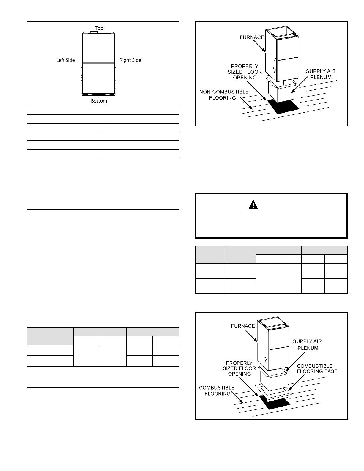
Top 0
* Front 0
Back 0
Sides 0†
Vent 0
Floor NC‡
* Front clearance in alcove installation must be 24 in. (610
mm). Maintain a minimum of 24 in. (610 mm) for front service
access.
† Allow proper clearances to accommodate condensate trap.
‡ The furnace may be installed on a combustible wood oor if
an optional additive base is installed between the furnace and
the combustible oor.
Figure 14. Downow Application Installation
Clearances
Installation on Non-Combustible Flooring
1. Cut oor opening keeping in mind clearances listed
on unit rating plate. Also keep in mind gas supply
connections, electrical supply, ue and air intake
connections and sucient installation and servicing
clearances. See Table 1 for correct oor opening size.
2. Flange warm air plenum and lower the plenum into the
opening.
3. Set the unit over the plenum and seal the plenum to
the unit.
4. Ensure that the seal is adequate.
Figure 15.
Installation on Combustible Flooring
1. When unit is installed on a combustible oor, a
downow combustible ooring base must be installed
between the furnace and the oor. The base must be
ordered separately. See Table 2 for opening size to
cut in oor.
CAUTION
The furnace and combustible ooring base shall not be
installed directly on carpeting, tile, or other combustible
material other than wood ooring.
Cabinet
Width
B cabinet
(17.5”)
C cabinet
(21”)
Catalog
Number
11M60
11M61 22-3/4 578
Table 2. Combustible Flooring Base Opening Size
Front to Rear Side to Side
in. mm in. mm
18-3/4 476
22 559
Cabinet Width
B cabinet (17.5”)
C cabinet (21”) 20-1/8 511
NOTE: Floor opening dimensions listed are 1/4 in. (6 mm)
larger than the unit opening. See dimension drawing on Page
2.
Front to Rear Side to Side
in. mm in. mm
16-5/8 422
19-3/4 502
Table 1. Non-Combustible Floor Opening Size
508405-01 Page 11 of 53Issue 2332
Figure 16.
Page 12
2. After opening is cut, set the combustible ooring base
into opening.
3. Check berglass strips on the combustible ooring
base to make sure they are properly glued and
positioned.
4. Lower supply air plenum into the combustible ooring
base until plenum anges seal against berglass
strips.
NOTE: Be careful not to damage berglass strips.
Check for a tight seal.
5. Set the furnace over the plenum.
6. Ensure that the seal between the furnace and plenum
is adequate.
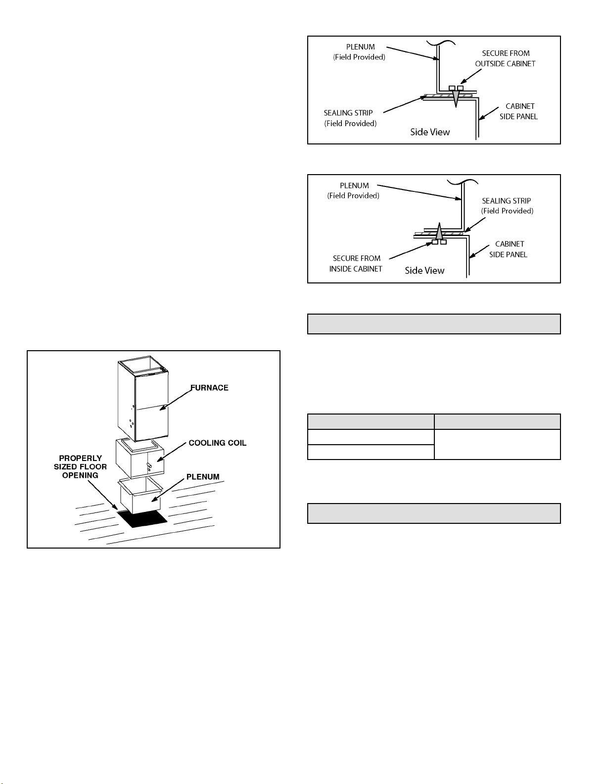
Installation on Cooling Coil Cabinet
NOTE: Downow combustible ooring kit is not used.
1. Refer to reverse-ow coil installation instructions for
correctly sized opening in oor and installation of
cabinet.
2. When cooling cabinet is in place, set and secure the
furnace according to the instructions that are provided
with the cooling coil. Secure the furnace to the cabinet.
3. Seal the cabinet and check for air leaks.
Figure 18.
Figure 19.
Filters
Figure 17.
Return Air Opening - Downow Units
Return air may be brought in only through the top opening of
a furnace installed in the downow position. The following
steps should be taken when installing plenum:
1. Bottom edge of plenum should be anged with a
hemmed edge (see Figure 18 or Figure 19).
2. Sealing strips should be used to ensure an airtight
seal between the cabinet and the plenum.
3. In all cases, plenum should be secured to top of
furnace using sheet metal screws.
4. Make certain that an adequate seal is made.
This unit is not equipped with a lter or rack. A eld provided
lter is required for the unit to operate properly. Table 3 lists
recommended lter sizes.
A lter must be in place whenever the unit is operating.
Furnace Cabinet Width Filter Size
17-1/2”
21”
Table 3.
16 x 25 x 1 (1)
Duct System
Use industry-approved standards to size and install the
supply and return air duct system. This will result in a quiet
and low-static system that has uniform air distribution.
NOTE: This furnace is not certied for operation in heating
mode (indoor blower operating at selected heating speed)
with an external static pressure which exceeds 0.8 inches
w.c. Operation at these conditions may result in improper
limit operation.
Supply Air Plenum
If the furnace is installed without a cooling coil, a removable
access panel should be installed in the supply air duct. The
access panel should be large enough to permit inspection
(by reected light) of the heat exchanger for leaks after the
508405-01Page 12 of 53 Issue 2332
Page 13
furnace is installed. The furnace access panel must always
be in place when the furnace is operating and it must not
allow leaks into the supply air duct system.
Return Air Plenum
NOTE: Return air must not be drawn from a room where
this furnace, or any other gas-fueled appliance (i.e., water
heater), or carbon monoxide-producing device (i.e., wood
replace) is installed.
When return air is drawn from a room, a negative pressure
is created in the room. If a gas appliance is operating in
a room with negative pressure, the ue products can be
pulled back down the vent pipe and into the room. This
reverse ow of the ue gas may result in incomplete
combustion and the formation of carbon monoxide gas.
This toxic gas might then be distributed throughout the
house by the furnace duct system.
Use berglass sealing strips, caulking, or equivalent
sealing method between the plenum and the furnace
cabinet to ensure a tight seal. If a lter is installed, size the
return air duct to t the lter frame.
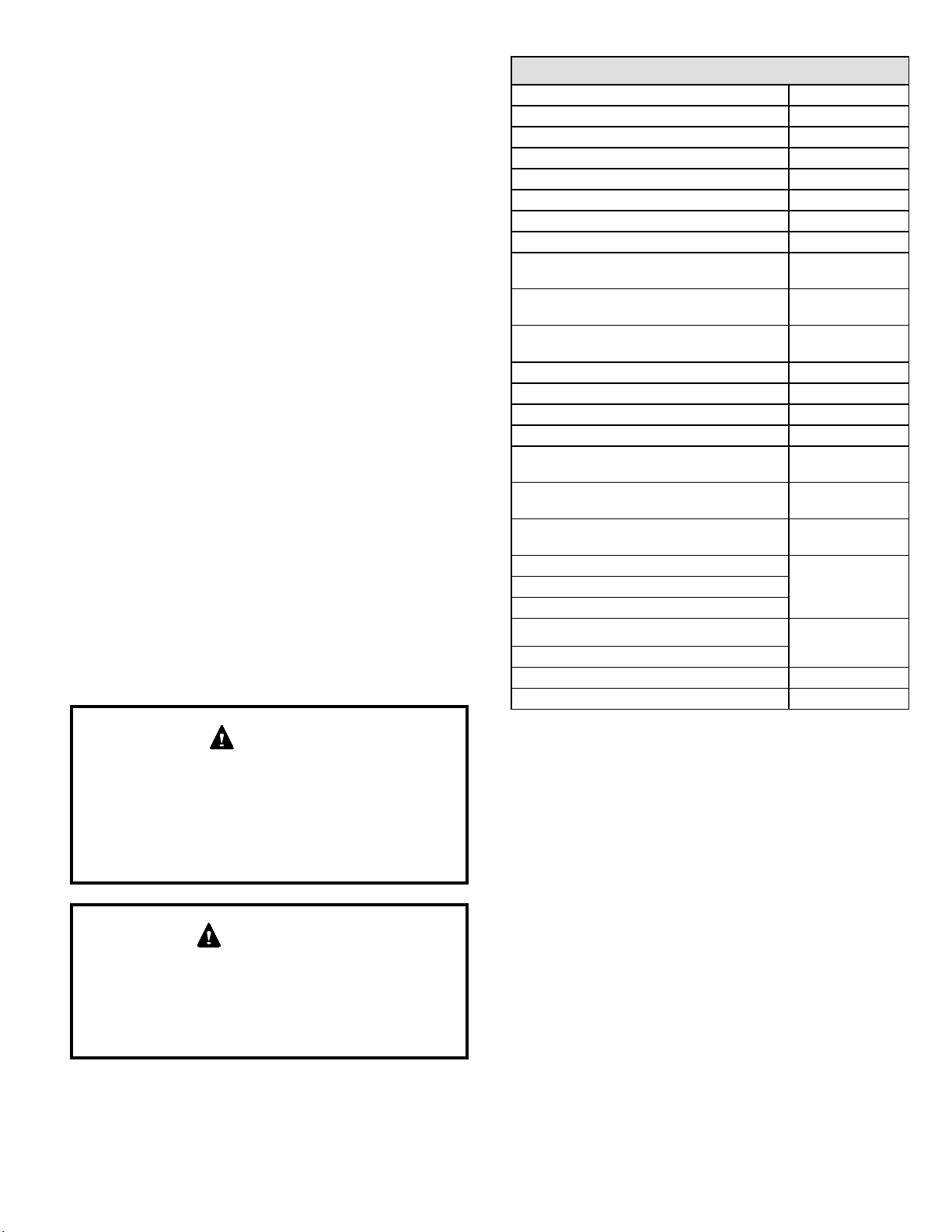
Pipe & Fittings Specications
All pipe, ttings, primer and solvent cement must conform
with American National Standard Institute and the American
Society for Testing and Materials (ANSI/ASTM) standards.
The solvent shall be free owing and contain no lumps,
undissolved particles or any foreign matter that adversely
aects the joint strength or chemical resistance of the
cement. The cement shall show no gelation, stratication,
or separation that cannot be removed by stirring. Refer to
Table 4 below for approved piping and tting materials.
Piping and Fittings Specications
Schedule 40 PVC (Pipe) D1785
Schedule 40 PVC (Fittings) D2466
Schedule 40 CPVC (Pipe) F441
Schedule 40 CPVC (Fittings) F438
SDR-21 PVC or SDR-26 PVC (Pipe) D2241
SDR-21 CPVC or SDR-26 CPVC (Pipe) F442
Schedule 40 ABS (Pipe) D1527
Schedule 40 ABS (Fittings) D2468
ABS-DWV (Drain Waste & Vent)
(Pipe & Fittings)
PVC-DWV (Drain Waste & Vent)
Pipe & Fittings)
PRIMER & SOLVENT CEMENT
PVC & CPVC Primer F656
PVC Solvent Cement D2564
CPVC Solvent Cement F493
ABS Solvent Cement D2235
PVC/CPVC/ABS All Purpose Cement For
Fittings & Pipe of the same material
ABS to PVC or CPVC Transition Solvent
Cement
CANADA PIPE & FITTING & SOLVENT
CEMENT
PVC & CPVC Pipe and Fittings
ABS to PVC or CPVC Transition Cement
POLYPROPYLENE VENTING SYSTEM
PolyPro® by Duravent
InnoFlue® by Centrotherm ULC-S636
ECCO Polypropylene Vent
TM
D2661
D2665
ASTM
SPECIFICATION
D2564, D2235,
F493
D3138
MARKING
ULCS636PVC & CPVC Solvent Cement
ULC-S636
ULC-S636
CAUTION
Solvent cements for plastic pipe are ammable liquids
and should be kept away from all sources of ignition.
Do not use excessive amounts of solvent cement when
making joints. Good ventilation should be maintained to
reduce re hazard and to minimize breathing of solvent
vapors. Avoid contact of cement with skin and eyes.
IMPORTANT
The exhaust and intake connections are made of PVC.
Use PVC primer and solvent cement when using PVC
vent pipe. When using ABS vent pipe, use transitional
solvent cement to make connections to the PVC tting
in the unit.
508405-01 Page 13 of 53Issue 2332
Table 4.
Use PVC primer and solvent cement or ABS solvent
cement meeting ASTM specications, refer to Table 4.
As an alternate, use all purpose cement, to bond ABS,
PVC, or CPVC pipe when using ttings and pipe made of
the same materials. Use transition solvent cement when
bonding ABS to either PVC or CPVC.
Low temperature solvent cement is recommended during
cooler weather. Metal or plastic strapping may be used as
vent pipe hangers. Uniformly apply a liberal coat of PVC
primer for PVC or use a clean dry cloth for ABS to clean
inside socket surface of tting and male end of pipe to
depth of tting socket.
Canadian Applications Only
Pipe, ttings, primer and solvent cement used to vent
(exhaust) this appliance must be certied to ULC S636 and
supplied by a single manufacturer as part of an approved
vent (exhaust) system. When bonding the vent system to
the furnace, use ULC S636 approved One-Step Transition
Cement to bond the pipe to the ue collar. In addition, the
Page 14
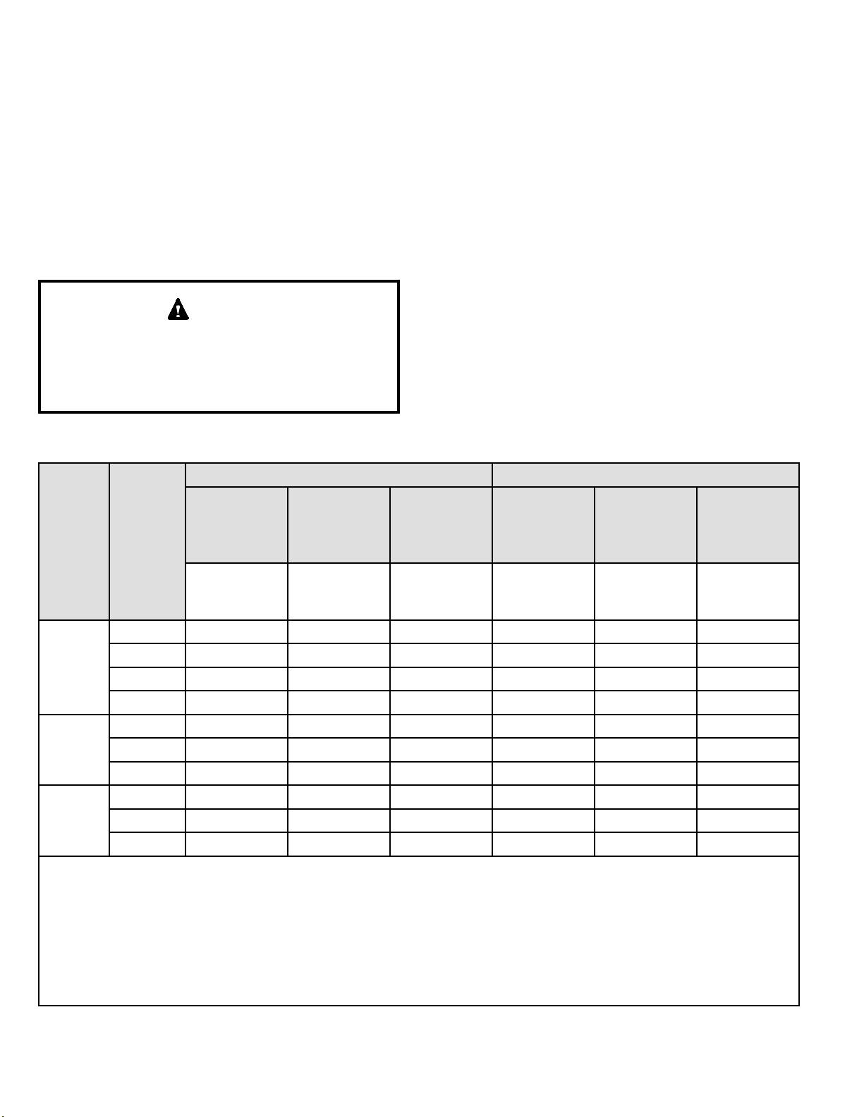
rst three feet of vent pipe from the furnace ue collar must
be accessible for inspection.
Table 5 lists the available exhaust termination kits. All vent
terminations are PVC.
Joint Cementing Procedure
All cementing of joints should be done according to the
specications outlined in ASTM D 2855.
NOTE: A sheet metal screw may be used to secure the
intake pipe to the connector, if desired. Use a drill or self
tapping screw to make a pilot hole.
DANGER
DANGER OF EXPLOSION!
Fumes from PVC glue may ignite during system check.
Allow fumes to dissipate for at least 5 minutes before
placing unit into operation.
1. Measure and cut vent pipe to desired length.
2. Debur and chamfer end of pipe, removing any ridges
or rough edges. If end is not chamfered, edge of pipe
may remove cement from tting socket and result in a
leaking joint.
3. Clean and dry surfaces to be joined.
4. Test t joint and mark depth of tting on outside of pipe.
5. Uniformly apply a liberal coat of PVC primer for PVC
or use a clean dry cloth for ABS to clean inside socket
surface of tting and male end of pipe to depth of tting
socket.
6. Promptly apply solvent cement to end of pipe and
inside socket surface of tting. Cement should be
applied lightly but uniformly to inside of socket. Take
care to keep excess cement out of socket. Apply
second coat to end of pipe.
NOTE: Time is critical at this stage. Do Not allow
primer to dry before applying cement.
STANDARD CONCENTRIC
Outdoor
VENT
Capacity
070
090
110
1
2 inch to 1-1/2 inch reducer required, must be eld provided.
* Requires eld-provided and installed 1-1/2” exhaust accelerator.
** Kit 51W11 is provided with a 1-1/2” accelerator, which must be used for all 70,000 furnace installations. When using 1-/2 in. piping,
the pipe must be transitioned to 2 in. pipe when used with the Flush Mount Kit.
† Termination kits 44W92, 44W93, 30G28 and 81J20 approved for use in Canadian installations to meet CSAB149.
†† The 44W92 concentric kit is provided with a 1-1/2” accelerator, which must be installed on the exhaust outlet when this kit is used
with the 70,000 furnaces. When using 1-1/2 in. piping, the pipe must be transitioned to 2 in. pipe when used with the Concentric
Kit.
PIPE DIA.
(in.)
1
1-1/2 YES YES
2 YES YES YES
2-1/2" YES YES YES
3 YES YES YES
2 YES YES YES YES
2-1/2" YES YES YES YES
3 YES YES YES YES
2 YES YES YES YES
2-1/2" YES YES YES YES
3 YES YES YES YES
Exhaust
Accelerator
(Dia. X Length)
1-1/2" x 12" 2" x 12" 51W11**
Outdoor
Exhaust
Accelerator
(Dia. X Length)
Flush Mount
Kit
1-1/2"
Concentric Kit
71M80
OR
+44W92++
2" Concentric
Kit
69M29
OR
+44W92++
3" Concentric
Kit
60L46
OR
44W93+
Table 5. Outdoor Termination Kits Usage
508405-01Page 14 of 53 Issue 2332
Page 15
7. Immediately after applying last coat of cement to pipe,
and while both inside socket surface and end of pipe
are wet with cement, forcefully insert end of pipe into
socket until it bottoms out. Turn PVC pipe 1/4 turn
during assembly (but not after pipe is fully inserted) to
distribute cement evenly. Do not turn ABS or cellular
core pipe.
NOTE: Assembly should be completed within 20
seconds after last application of cement. Hammer
blows should not be used when inserting pipe.
8. After assembly, wipe excess cement from pipe at end
of tting socket. A properly made joint will show a bead
around its entire perimeter. Any gaps may indicate
an improper defective assembly due to insucient
solvent.
9. Handle joints carefully until completely set.
Venting Practices
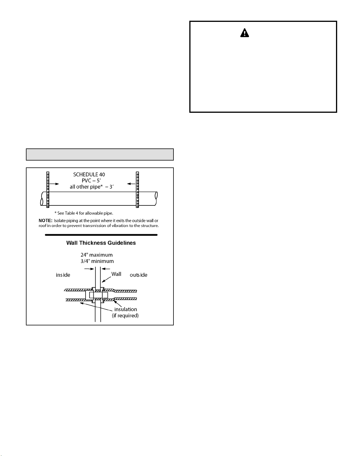
Figure 20. Piping Suspension Guidelines
Removal of the Furnace from Common Vent
In the event that an existing furnace is removed from
a venting system commonly run with separate gas
appliances, the venting system is likely to be too large to
properly vent the remaining attached appliances.
WARNING
CARBON MONOXIDE POISONING HAZARD
Failure to follow the steps outlined below for each
appliance connected to the venting system being
placed into operation could result in carbon monoxide
poisoning or death.
The following steps shall be followed for each appliance
connected to the venting system being placed into
operation, while all other appliances connected to the
venting system are not in operation.
1. Seal any unused openings in the common venting
system.
2. Inspect the venting system for proper size and
horizontal pitch. Determine that there is no blockage,
restriction, leakage, corrosion, or other deciencies
which could cause an unsafe condition.
3. Close all building doors and windows and all doors
between the space in which the appliances remaining
connected to the common venting system are located
and other spaces of the building. Turn ON clothes
dryers and any appliances not connected to the
common venting system. Turn ON any exhaust fans,
such as range hoods and bathroom exhausts, so they
will operate at maximum speed. Do not operate a
summer exhaust fan. Close replace dampers.
4. Follow the lighting instructions. Turn ON the appliance
that is being inspected. Adjust the thermostat so that
the appliance operates continuously.
5. After the main burner has operated for 5 minutes, test
for leaks of ue gases at the draft hood relief opening.
Use the ame of a match or candle.
6. After determining that each appliance connected to
the common venting system is venting properly, (step
3) return all doors, windows, exhaust fans, replace
dampers, and any other gas burning appliances to
their previous mode of operation.
7. If a venting problem is found during any of the
preceding tests, the common venting system must be
modied to correct the problems.
Resize the common venting system to the minimum vent
pipe size determined by using the appropriate tables in
Appendix G. These are in the current standards of the
National Fuel Gas Code ANSI Z223.1.
Conduct the following test while each appliance is operating
and the other appliances (which are not operating) remain
connected to the common venting system. If the venting
system has been installed improperly, you must correct the
system as indicated in the general venting requirements
section.
508405-01 Page 15 of 53Issue 2332
Page 16
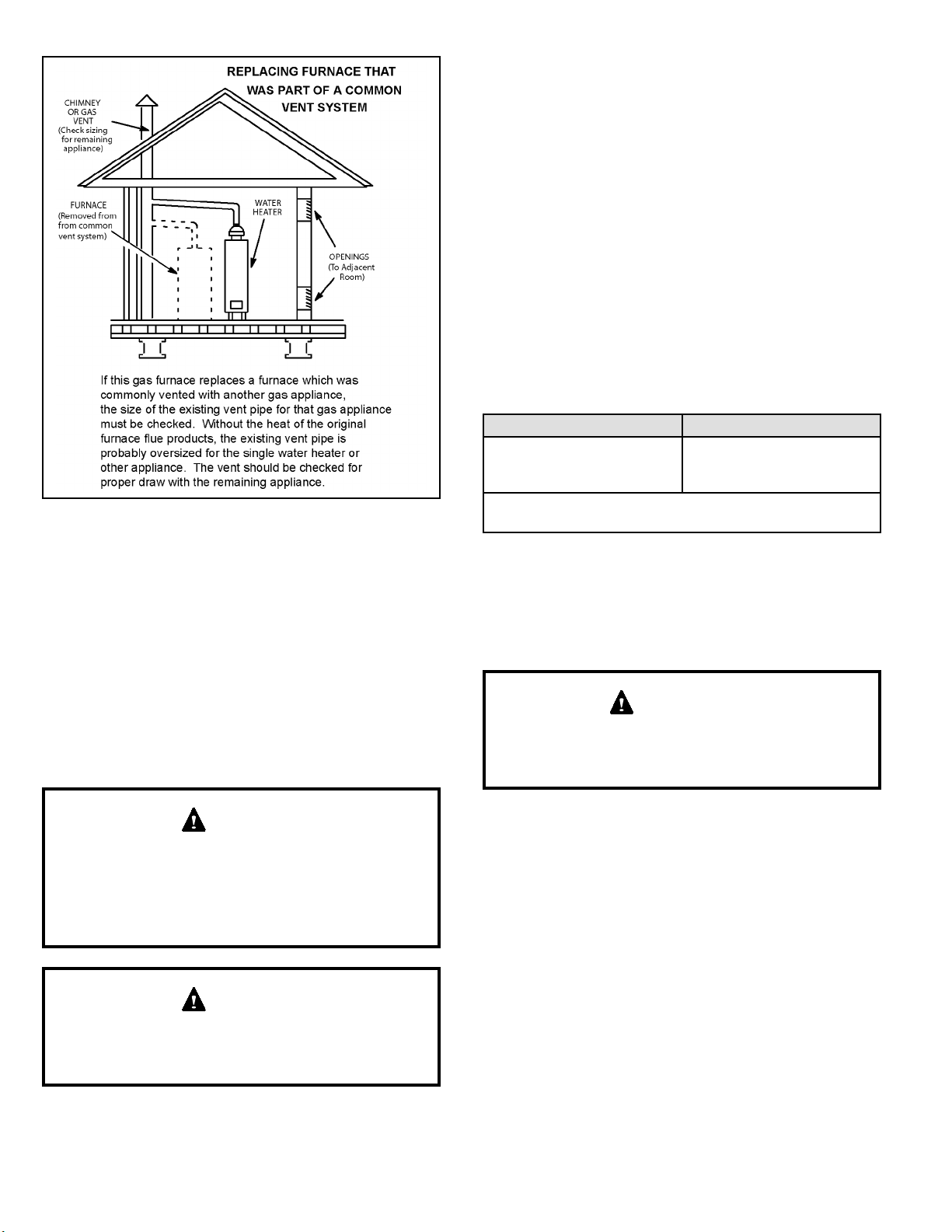
Figure 21.
Vent Piping Guidelines
This gas furnace can be installed as either a Non-Direct
Vent or a Direct Vent gas central furnace.
NOTE: In non-Direct Vent installations, combustion air is
taken from indoors and ue gases are discharged outdoors.
In Direct Vent installations, combustion air is taken from
outdoors and ue gases are discharged outdoors.
Intake and exhaust pipe sizing - Size pipe according to
Table 6 and Table 7A through Table 7C. Table 6 lists the
minimum vent pipe lengths permitted. Table 7A through
Table 7C lists the maximum pipe lengths permitted.
Regardless of the diameter of pipe used, the standard roof
and wall terminations described in section Exhaust Piping
Terminations should be used. Exhaust vent termination
pipe is sized to optimize the velocity of the exhaust gas as
it exits the termination.
Capacity Min. Vent Length*
15 ft. or
070, 090, 110
* Any approved termination may be added to the minimum
length listed.
5 ft. plus 2 elbows or
10 ft. plus 1 elbow
1. In areas where piping penetrates joist or interior walls,
hole must be large enough to allow clearance on all
sides of pipe through center of hole using a hanger.
2. When furnace is installed in a residence where unit
is shut down for an extended period of time, such
as a vacation home, make provisions for draining
condensate collection trap and lines.
Exhaust Piping
Route piping to outside of structure. Continue with
installation following instructions given in piping termination
section.
CAUTION
Do not discharge exhaust into an existing stack or
stack that also serves another gas appliance. If vertical
discharge through an existing unused stack is required,
insert PVC pipe inside the stack until the end is even
with the top or outlet end of the metal stack.
Table 6. Minimum Vent Pipe Lengths
In some applications which permit the use of several
dierent sizes of vent pipe, a combination vent pipe may
be used. Contact Allied Air Technical Service for assistance
in sizing vent pipe in these applications.
IMPORTANT
Do not use screens or perforated metal in exhaust or
intake terminations. Doing so will cause freeze-ups and
may block the terminations.
CAUTION
The exhaust vent pipe operates under positive pressure
and must be completely sealed to prevent leakage of
combustion products into the living space.
508405-01Page 16 of 53 Issue 2332
Page 17
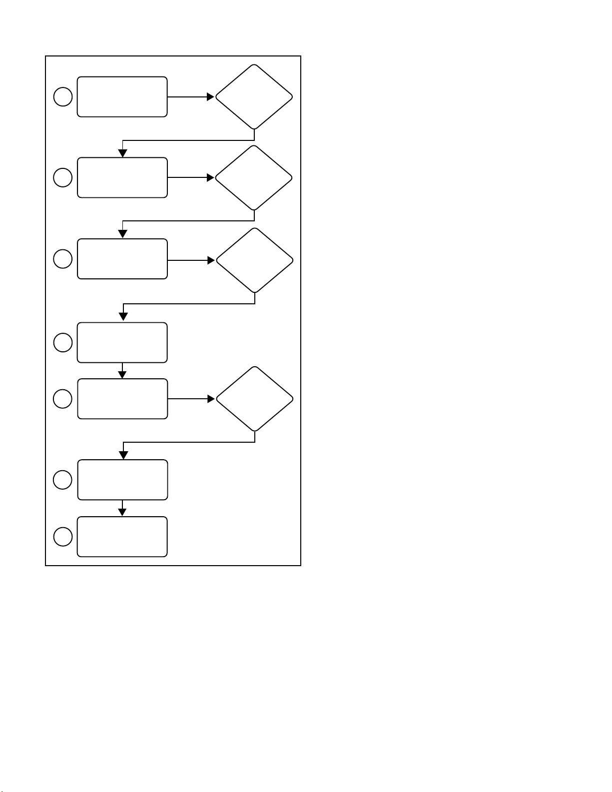
Use the following steps to correctly size vent pipe diameter.
070, 090,
110
Standard or
Concentric?
See Table 5
Intake or
Exhaust?
1-1/2”, 2”,
2-1/2”
or 3”
Furnace capacity?
1
Which termination?
2
Which needs most
elbows?
3
How many?
4
Desired pipe size?
5
What is the altitude?
6
Use Table 7 to find
max pipe length.
7
Figure 22.
508405-01 Page 17 of 53Issue 2332
Page 18
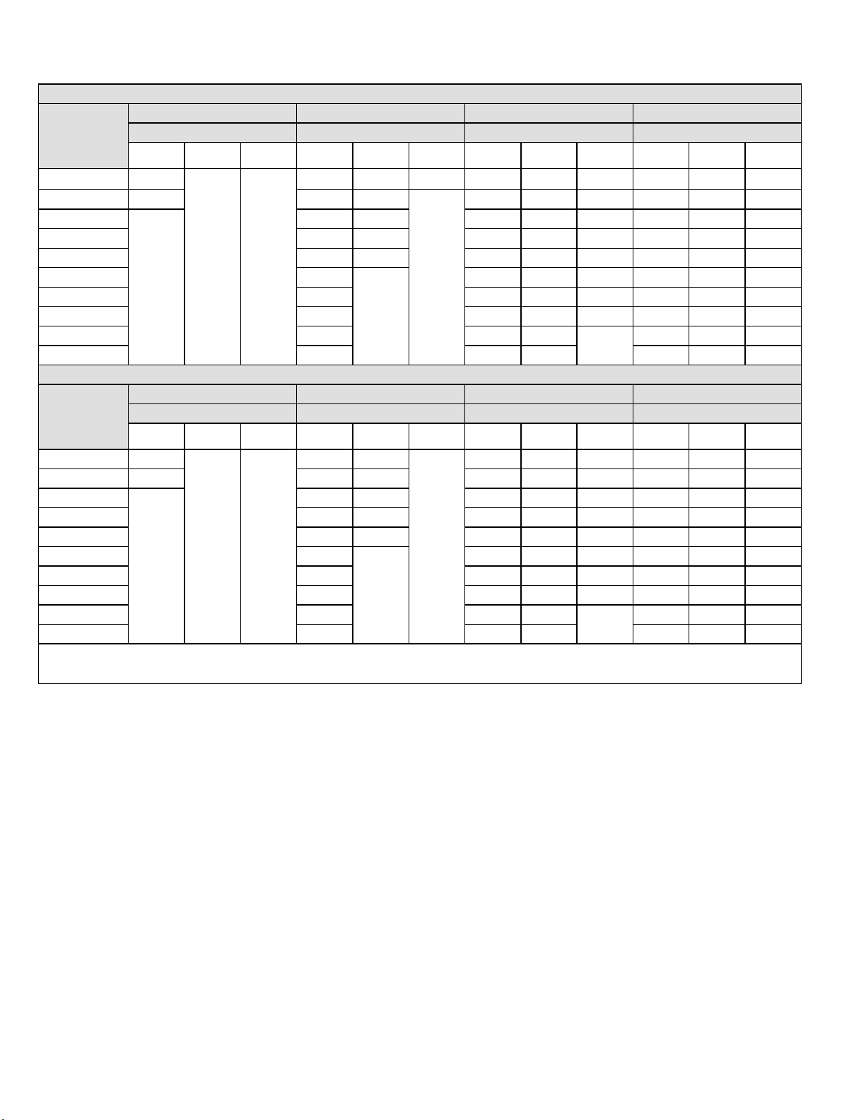
Maximum Allowable Intake or Exhaust Vent Length in Feet
Standard Termination at Elevation 0 - 4,500 ft
Number of
90° Elbows
Used
1 15
2 10 46 24
3
4 36 14 85 63 28 107 88 88
5 31 9 80 58 23 102 83 83
6 26
7 21 70 48 13 92 73 73
8 16 65 43 8 87 68 68
9 11 60 38
10 6 55 33 77 58 58
Number of
90° Elbows
Used
1 15
2 10 46 24 95 73 38 11 7 98 98
3
4 36 14 85 63 28 107 88 88
5 31 9 80 58 23 102 83 83
6 26
7 21 70 48 13 92 73 73
8 16 65 43 8 87 68 68
9 11 60 38
10 n/a 55 33 77 58 58
*Size intake and exhaust pipe length separately. Values in table are for intake OR Exhaust, not combined total. Both Intake and
Exhaust must be same pipe size.
1-1/2” Pipe 2” Pipe 2-1/2” Pipe 3" Pipe
Capacity Capacity Capacity Capacity
070 090 110 070 090 11 0 070 090 110 070 090 11 0
51 29 9 100 78 43 122 103 103
95 73 38 117 98 98
41 19 90 68 33 112 93 93
n/a n/a
n/a
n/a
Standard Termination at Elevation 4,501 - 10,000 ft
1-1/2” Pipe 2” Pipe 2-1/2” Pipe 3" Pipe
Capacity Capacity Capacity Capacity
070 090 110 070 090 11 0 070 090 110 070 090 11 0
51 29
41 19 90 68 33 112 93 93
n/a n/a
n/a
n/a
n/a
n/a
75 53 18 97 78 78
n/a
100 78 43 122 103 103
75 53 18 97 78 78
n/a
82 63 63
82 63 63
Table 7A.
508405-01Page 18 of 53 Issue 2332
Page 19
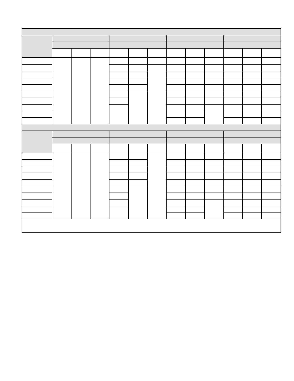
Maximum Allowable Intake or Exhaust Vent Length in Feet
Concentric Termination at Elevation 0 - 4,500 ft
Number of
90° Elbows
Used
1
2 38 22
3 33 17 80 64 29 96 89 89
4 28 12 75 59 24 91 84 84
5 23 7 70 54 19 86 79 79
6 18
7 13 60 44 9 76 69 69
8
9 50 34 66 59 59
10 45 29 61 54 54
Number of
90° Elbows
Used
1
2 38 22 85 69 34 101 94 94
3 33 17 80 64 29 96 89 89
4 28 12 75 59 24 91 84 84
5 23 7 70 54 19 86 79 79
6 18
7 13 60 44 9 76 69 69
8 8 55 39
9
10 45 29 61 54 54
*Size intake and exhaust pipe length separately. Values in table are for intake OR Exhaust, not combined total. Both Intake and
Exhaust must be same pipe size.
1-1/2” Pipe 2” Pipe 2-1/2" Pipe 3" Pipe
Capacity Capacity Capacity Capacity
070 090 110 070 090 11 0 070 090 110 070 090 11 0
43 27 7 90 74 39 106 99 99
85 69 34 101 94 94
n/a n/a n/a
n/a
n/a
Concentric Termination at Elevation 4,501 - 10,000 ft
1-1/2” Pipe 2” Pipe 2-1/2" Pipe 3" Pipe
Capacity Capacity Capacity Capacity
070 090 110 070 090 11 0 070 090 110 070 090 11 0
43 27
n/a n/a n/a
n/a
n/a
n/a
n/a
65 49 14 81 74 74
55 39
n/a
90 74 39 106 99 99
65 49 14 81 74 74
50 34 66 59 59
n/a
71 64 64
71 64 64
Table 7B.
508405-01 Page 19 of 53Issue 2332
Page 20
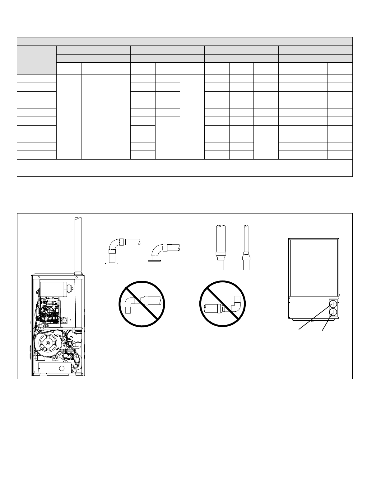
Maximum Allowable Exhaust Vent Length Using Ventilated Attic or Crawl Space for Intake Air in Feet
Standard Termination at Elevation 0 - 10,000 ft
Number of
90° Elbows
Used
1
1-1/2” Pipe 2” Pipe 2-1/2" Pipe 3" Pipe
Capacity Capacity Capacity Capacity
070 090 110 070 090 11 0 070 090 110 070 090 11 0
41 24
85 63 28 102 83 83
2 36 19 80 58 23 97 78 78
3 31 14 75 53 18 92 73 73
4 26 9 70 48 13 87 68 68
5 21 4 65 43 8 82 63 63
6 16
7 11 55 33
8 6 50 28 67 48 48
9 1 45 23 62 43 43
n/a n/a n/a
n/a
n/a
60 38 3 77 58 58
72 53 53
n/a
10 n/a 40 18 57 38 38
NOTE: Additional vent pipe and elbows used to terminate the vent pipe outside the structure must be included in the total vent length
calculation.
Table 7C.
Pipe size determined in table 7.
2”
2”
* When transitioning up in pipe size, use the shortest length of 2” PVC pipe possible.
NOTE: Exhaust pipe and intake pipe must be the same diameter.
2”
2”
or
DO NOT transition
from smaller to larger
pipe in horizontal runs
of exhaust pipe.
2”
3”
TRANSITION
*2”
DO NOT transition
from larger to smaller
pipe in horizontal runs
of exhaust pipe.
or
NOTE: 1-1/2” Vent Pipe
Diameter Allowed Only
on 045/070 Units
1-1/2”
TRANSITION
*2”
Figure 23. Typical Exhaust Pipe Connections
INTAKE
EXHAUST
TOP VIEW
508405-01Page 20 of 53 Issue 2332
Page 21
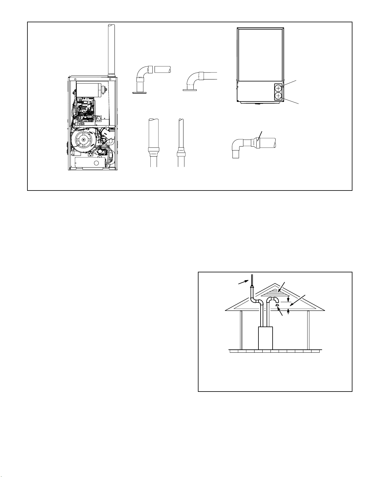
Pipe size determined in table 7.
2”
2”
3”
TRANSITION
*2”
* When transitioning up in pipe size, use the shortest length of 2” PVC pipe possible.
NOTE: Exhaust pipe and intake pipe must be the same diameter.
2”
or
or
Figure 24. Typical Intake Pipe Connections (Direct Vent Applications)
Intake Piping
This furnace may be installed in either direct vent or nondirect vent applications. In non-direct vent applications,
when intake air will be drawn into the furnace from
the surrounding space, the indoor air quality must be
considered. Guidelines listed in Combustion, Dilution and
Ventilation Air section must be followed.
2”
NOTE: 1-1/2” Vent Pipe
Diameter Allowed Only
on 045/070 Units
1-1/2”
TRANSITION
*2”
2”
INTAKE
EXHAUST
*2”
TOP VIEW
TRANSITION
*2”
3”
2. If intake air is drawn from a ventilated crawl space
(Figure 26) or ventilated attic (Figure 25) the exhaust
vent length must not exceed those listed in Table 7C.
If 3” diameter pipe is used, reduce to 2” diameter pipe
to accommodate the debris screen.
3. Use a sheet metal screw to secure the intake pipe to
the connector, if desired.
Use the following steps when installing the unit in Direct
Vent applications, where combustion air is taken from
outdoors and ue gases are discharged outdoors. The
provided air intake screen must not be used in direct vent
applications (outdoors).
1. Use cement or a sheet metal screw to secure the
intake pipe to the inlet air connector.
2. Route piping to outside of structure. Continue with
installation following instructions given in general
guide lines for piping terminations and intake and
exhaust piping terminations for direct vent sections.
Refer to Table 7A through Table 7C for pipe sizes.
Use the following steps when installing the unit in NonDirect Vent applications where combustion air is taken
from indoors and ue gases are discharged outdoors.
1. Use eld-provided materials and the factory-provided
air intake screen to route the intake piping. Maintain
a minimum clearance of 3” (76 mm) around the air
intake opening. The air intake opening (with the
protective screen) should always be directed forward,
or sideways.
Roof Terminated
Exhaust Pipe
Ventilation Louvers
*Intake Debris
Screen
(Provided)
Furnace
Inlet Air
(Minimum 12 in.
(305mm) above
Attic Floor)
* See Maximum Vent Lengths table
NOTE-The inlet and outlet air openings shall each have a
free area of at least one square inch per 4,000 Btu (645mm2
per 1.17kW) per hour of the total input rating of all equipment
in the enclosure.
Figure 25. Equipment in Conned Space
(Inlet Air from Ventilated Attic and Outlet Air to
Outside)
508405-01 Page 21 of 53Issue 2332
Page 22
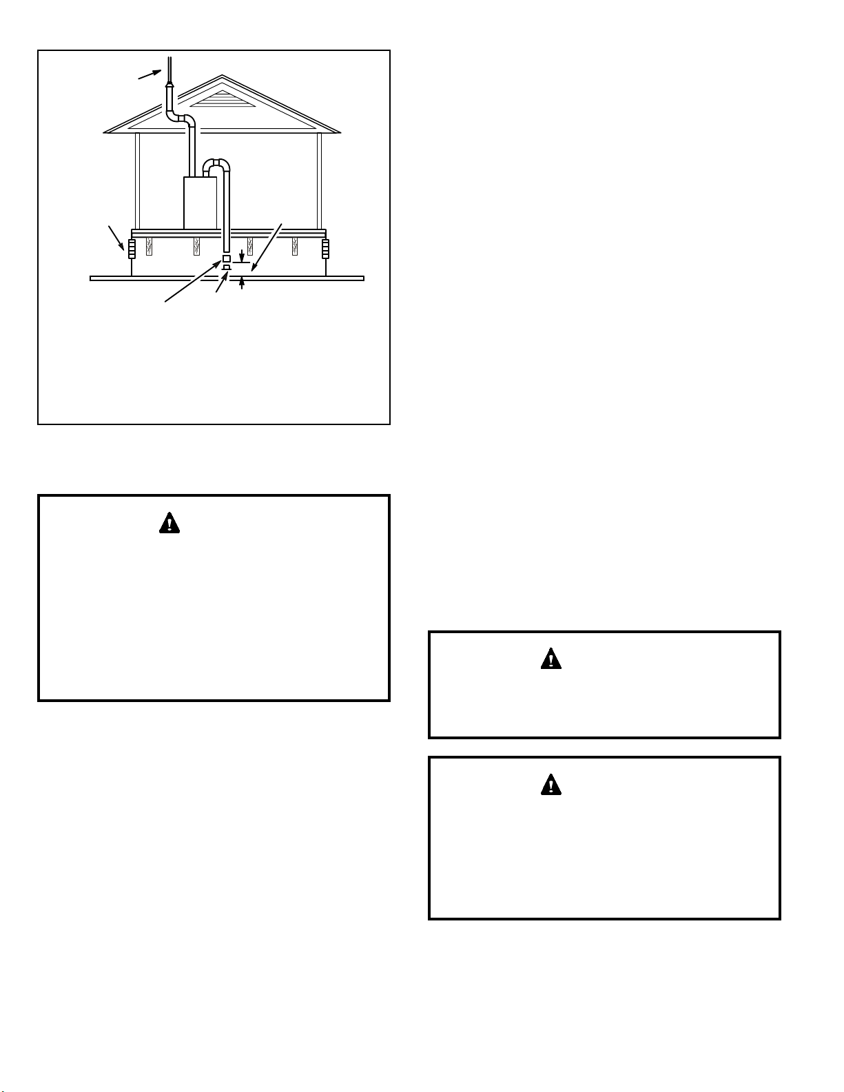
Roof Terminated
Exhaust Pipe
Inlet Air
Minimum
Ventilation
Louvers
(Crawl Space)
Coupling or
3 in. to 2 in.
Transition
(Field Provided)
Furnace
12 in. (305mm)
above Crawl
Space Floor
*Intake Debris Screen Provided
* See Maximum Vent Lengths table
NOTE-The inlet and outlet air openings shall each have a
free area of at least one square inch per 4,000 Btu (645mm
per 1.17kW) per hour of the total input rating of all equipment
in the enclosure.
2
Figure 26. Equipment in Conned Space
(Inlet Air from Ventilated Crawl Space and Outlet Air
to Outside)
WARNING
If this unit is being installed in an application with
combustion air coming in from a space serviced by an
exhaust fan, power exhaust fan, or other device which
may create a negative pressure in the space, take care
when sizing the inlet air opening. The inlet air opening
must be sized to accommodate the maximum volume
of exhaust air as well as the maximum volume of
combustion air required for all gas appliances serviced
by this space.
General Guidelines for Vent Terminations
In Non-Direct Vent applications, combustion air is taken
from indoors and the ue gases are discharged to the
outdoors. This unit is then classied as a non-direct vent,
Category IV gas furnace.
In Direct Vent applications, combustion air is taken from
outdoors and the ue gases are discharged to the outdoors.
This unit is then classied as a direct vent, Category IV gas
furnace.
In both Non-Direct Vent and Direct Vent applications, the
vent termination is limited by local building codes. In the
absence of local codes, refer to the current National Fuel
Gas Code ANSI Z223-1/NFPA 54 in U.S.A., and current
CSA-B149 Natural Gas and Propane Installation Codes in
Canada for details.
Position termination according to location given in Figure
28 or Figure 29. In addition, position termination so it is
free from any obstructions and 12” above the average
snow accumulation.
At vent termination, care must be taken to maintain
protective coatings over building materials (prolonged
exposure to exhaust condensate can destroy protective
coatings). It is recommended that the exhaust outlet not be
located within 6 feet (1.8 m) of a condensing unit because
the condensate can damage the painted coating.
NOTE: See Table 8 for maximum allowed exhaust pipe
length without insulation in unconditioned space during
winter design temperatures below 32° F (0° C). If required,
exhaust pipe should be insulated with 1/2” (13 mm),
Armaex or equivalent when run through an unconditioned
area. In extremely cold climate areas with temperature
below 20° F (6.7° C) it is recommended that 3/4” (19 mm)
Armaex or equivalent be used. Insulation on outside
runs of exhaust pipe should be painted or wrapped to
protect insulation from deterioration in accordance with
the insulation manufacturers recommendation. Exhaust
pipe insulation may not be necessary in some specic
applications.
NOTE: During extremely cold temperatures, below
approximately 20° F (6° C), units with long runs of vent
pipe through unconditioned space, even when insulated,
may form ice in the exhaust termination that prevents the
unit from operating properly. Longer run times of at least 5
minutes will alleviate most icing problems. Also, a heating
cable may be installed on exhaust piping and termination
to prevent freeze-ups. Heating cable installation kits are
available, see unit specication sheets for part numbers.
IMPORTANT
Do not use screens or perforated metal in exhaust
terminations. Doing so will cause freeze-ups and may
block the terminations.
IMPORTANT
For Canadian Installations Only:
In accordance to CSA International B149 installation
codes, the minimum allowed distance between the
combustion air intake inlet and the exhaust outlet of
other appliances shall not be less than 12 inches (305
mm).
508405-01Page 22 of 53 Issue 2332
Page 23
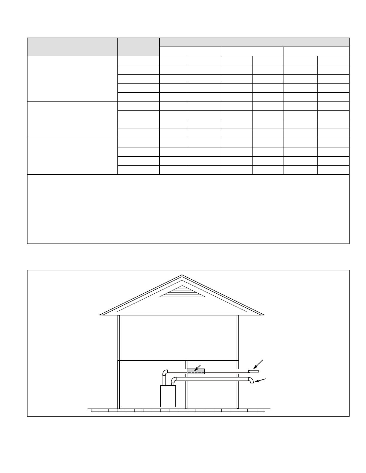
Maximum Allowable Exhaust Vent Pipe Length3 (in ft.) without Insulation in Unconditioned Space for Winter Design
Temperatures
Winter Design Temperatures
(ºC)
1
ºF
Vent Pipe
Diameter
070 090 110
PVC
2
PP PVC
Unit Input Size
2
PP PVC
2
PP
1-1/2 in. 20 N/A N/A N/A N/A N/A
32 to 21
(0 to -6)
2 in. 33 30 46 42 30 30
2-1/2 in. 26 N/A 37 N/A 36 N/A
3 in. 21 21 30 30 29 29
1-1/2 in. 20 N/A N/A N/A N/A N/A
20 to 1
(-7 to -17)
2 in. 19 17 28 25 27 24
2-1/2 in. 14 N/A 21 N/A 20 N/A
3 in. 9 9 16 16 14 14
1-1/2 in. 13 N/A N/A N/A N/A N/A
0 to -20
(-18 to -29)
2 in. 12 10 19 16 18 15
2-1/2 in. 7 N/A 13 N/A 12 N/A
3 in. N/A N/A 8 8 7 7
1
Refer to 99% Minimum Design Temperature table provided in the current edition of the ASHRAE Fundamentals Handbook.
2
Poly-Propylene vent pipe (PP) by Duravent and Centrotherm
3
Vent length in table is equivalent length. Each elbow is equivalent to 5ft of straight pipe and should be included when measuring
total length.
NOTE - Concentric terminations are the equivalent of 5’ and should be considered when measuring pipe length.
NOTE- Maximum uninsulated vent lengths listed may include the termination (vent pipe exterior to the structure ) and cannot exceed
5 linear feet or the maximum allowable intake or exhaust vent length listed in Table 6 or Table 7A through Table 7C.
NOTE - If insulation is required an unconditioned space, it must be located on the pipe closed to the furnace.
Conditioned
Space
Table 8.
Conditioned
Space
Pipe Insulation
Unconditioned
Space
Exhaust
Pipe
Intake
Pipe
Figure 27. Insulating Exhaust Pipe in an Unconditioned Space
508405-01 Page 23 of 53Issue 2332
Page 24
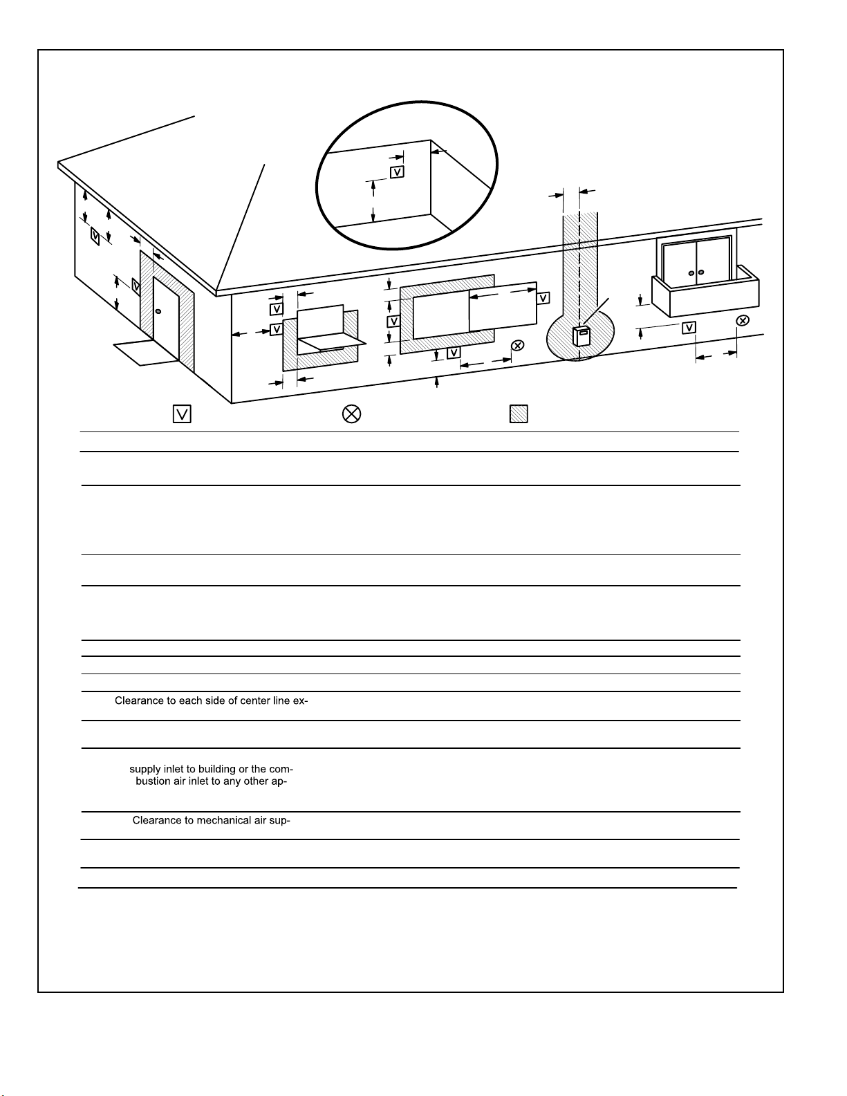
VENT TERMINATION CLEARANCES
FOR NON-DIRECT VENT INSTALLATIONS IN THE US AND CANADA
INSIDE CORNER
DETAIL
G
D
A
E
B
L
C
Fixed
F
Closed
Operable
B
B
B
VENT TERMINAL
AIR SUPPLY INLET
US Installations
A =
B =
C =
Clearance above grade, veranda,
porch, deck or balcony
Clearance to window or
door that may be opened
Clearance to permanently
12 inches (305mm) or 12 inches (305mm)
above average snow accumulation.
4 feet (1.2 m) below or to side of opening;
1 foot (30cm) above opening
closed window
Vertical clearance to ventilated soffit
D =
located above the terminal within a
* Equal to or greater than soffit depth.
horizontal distance of 2 feet (610 mm)
from the center line of the terminal
E =
F =
G =
Clearance to unventilated soffit
Clearance to outside corner
Clearance to inside corner
H =
tended above meter / regulator assembly
I =
Clearance to service regulator
vent outlet
J =
Clearance to non-mechanical air
* Equal to or greater than soffit depth.
* No minimum to outside corner * No minimum to outside corner
3 feet (.9m) within a height 15 feet (4.5m)
*
above the meter / regulator assembly
* 3 feet (.9m)
4 feet (1.2 m) below or to side of opening;
1 foot (30 cm) above opening
pliance
K =
ply inlet
L =
Clearance above paved sidewalk or
paved driveway located on public property
M =
Clearance under veranda, porch, deck or balcony
1
In accordance with the current ANSI Z223.1/NFPA 54 Natural Fuel Gas Code
In accordance with the current CSA B149.1, Natural Gas and Propane Installation
2
Code
†
A vent shall not terminate directly above a sidewalk or paved driveway that is
located between two single family dwellings and serves both dwellings.
‡
Permitted only if veranda, porch, deck or balcony is fully open on a minimum of
two sides beneath the floor. Avoiding this location is recommended if possible.
3 feet (.9m) above if within 10 feet
(3m) horizontally
7 feet (2.1m)†
*12 inches (305mm)‡
Operable
A
* 12”
H
Fixed
Closed
J
B
I
M
K
AREA WHERE TERMINAL
IS NOT PERMITTED
1
Canadian Installations
2
12 inches (305mm) or 12 inches (305mm)
above average snow accumulation.
6 inches (152mm) for appliances <10,000
Btuh (3kw), 12 inches (305mm) for
appliances > 10,000 Btuh (3kw) and
<100,000 Btuh (30kw), 36 inches (.9m)
for appliances > 100,000 Btuh (30kw)
* 12”
* Equal to or greater than soffit depth.
* Equal to or greater than soffit depth.
**
3 feet (.9m) within a height 15 feet (4.5m)
above the meter / regulator assembly
3 feet (.9m)
6 inches (152mm) for appliances <10,000
Btuh (3kw), 12 inches (305mm) for
appliances > 10,000 Btuh (3kw) and
<100,000 Btuh (30kw), 36 inches (.9m)
for appliances > 100,000 Btuh (30kw)
6 feet (1.8m)
7 feet (2.1m)†
12 inches (305mm)‡
*For clearances not specified in ANSI Z223.1/NFPA 54 or CSA
B149.1, clearance will be in accordance with local installation
codes and the requirements of the gas supplier and these
installation instructions.”
NOTE - This figure is intended to illustrate clearance
requirements and does not serve as a substitute for locally
adopted installation codes.
Figure 28. Vent Termination Clearances
For Non-Direct Vent Installations in the USA and Canada
508405-01Page 24 of 53 Issue 2332
Page 25
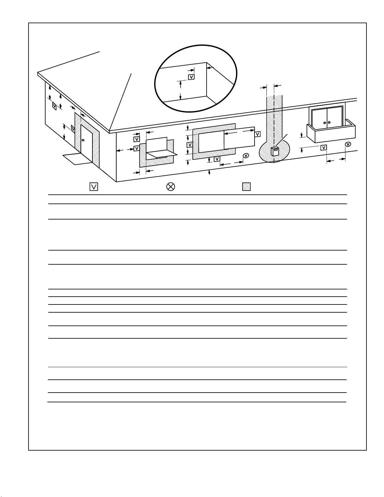
VENT TERMINATION CLEARANCES
FOR DIRECT VENT INSTALLATIONS IN THE USA AND CANADA
INSIDE CORNER
DETAIL
G
D
A
E
B
L
C
Fixed
F
Closed
Operable
B
B
B
VENT TERMINAL
AIR SUPPLY INLET
US Installations
A =
B =
Clearance above grade, veranda,
porch, deck or balcony
Clearance to window or
door that may be opened
12 inches (305mm) or 12 inches (305mm)
above average snow accumulation.
6 inches (152mm) for appliances <10,000
Btuh (3kw), 9 inches (228mm) for ap-
pliances > 10,000 Btuh (3kw) and <50,000
Btuh (15kw), 12 inches (305mm) for ap-
pliances > 50,000 Btuh (15kw)
C =
Clearance to permanently
closed window
Vertical clearance to ventilated soffit
D =
located above the terminal within a
horizontal distance of 2 feet (610mm)
* Equal to or greater than soffit depth* Equal to or greater than soffit depth
from the center line of the terminal
E =
F =
G =
H =
Clearance to unventilated soffit
Clearance to outside corner
Clearance to inside corner
Clearance to each side of center line ex-
tended above meter / regulator assembly
I =
Clearance to service regulator
vent outlet
J =
Clearance to non-mechanical air
supply inlet to building or the com-
bustion air inlet to any other ap-
pliance
* Equal to or greater than soffit depth * Equal to or greater than soffit depth
* No minimum to outside corner
3 feet (.9m) within a height 15 feet (4.5m)
above the meter / regulator assembly
*
3 feet (.9m)
6 inches (152mm) for appliances <10,000
Btuh (3kw), 9 inches (228mm) for ap-
pliances > 10,000 Btuh (3kw) and <50,000
Btuh (15kw), 12 inches (305mm) for ap-
pliances > 50,000 Btuh (15kw)
K =
Clearance to mechanical air sup-
ply inlet
Clearance above paved sidewalk or
L =
paved driveway located on public property
Clearance under veranda, porch, deck or balcony
M =
In accordance with the current ANSI Z223.1/NFPA 54 Natural Fuel Gas Code
1
In accordance with the current CSA B149.1, Natural Gas and Propane Installation
2
Code
†
A vent shall not terminate directly above a sidewalk or paved driveway that is
located between two single family dwellings and serves both dwellings.
‡
Permitted only if veranda, porch, deck or balcony is fully open on a minimum of
two sides beneath the floor. Avoiding this location is recommended if possible.
3 feet (.9m) above if within 10 feet
(3m) horizontally
* 7 feet (2.1m)
*12 inches (305mm)‡
Operable
A
* 12”
*
H
Fixed
Closed
J
B
I
M
K
AREA WHERE TERMINAL
IS NOT PERMITTED
1
Canadian Installations
2
12 inches (305mm) or 12 inches (305mm)
above average snow accumulation.
6 inches (152mm) for appliances <10,000
Btuh (3kw), 12 inches (305mm) for
appliances > 10,000 Btuh (3kw) and
<100,000 Btuh (30kw), 36 inches (.9m)
for appliances > 100,000 Btuh (30kw)
* 12”
* No minimum to outside corner
*
3 feet (.9m) within a height 15 feet (4.5m)
above the meter / regulator assembly
3 feet (.9m)
6 inches (152mm) for appliances <10,000
Btuh (3kw), 12 inches (305mm) for
appliances > 10,000 Btuh (3kw) and
<100,000 Btuh (30kw), 36 inches (.9m)
for appliances > 100,000 Btuh (30kw)
6 feet (1.8m)
7 feet (2.1m)†
12 inches (305mm)‡
*For clearances not specified in ANSI Z223.1/NFPA 54 or CSA
B149.1, clearance will be in accordance with local installation
codes and the requirements of the gas supplier and these
installation instructions.”
NOTE - This figure is intended to illustrate clearance
requirements and does not serve as a substitute for locally
adopted installation codes.
Figure 29. Vent Termination Clearances
For Direct Vent installations in the USA and Canada
508405-01 Page 25 of 53Issue 2332
Page 26
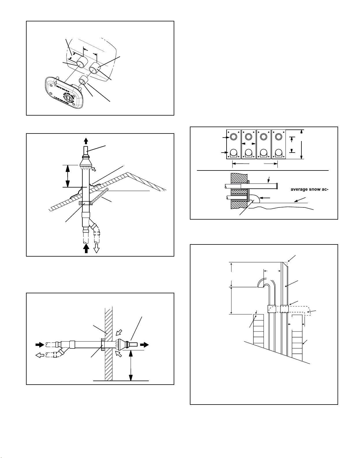
Details of Intake and Exhaust Piping
Terminations for Direct Vent Installations
NOTE: In Direct Vent installations, combustion air is taken
from outdoors and ue gases are discharged to outdoors.
NOTE: Flue gas may be slightly acidic and may adversely
aect some building materials. If any vent termination
is used and the ue gases may impinge on the building
material, a corrosion-resistant shield (minimum 24 inches
square) must be used to protect the wall surface. If the
optional tee is used, the protective shield is required.
The shield should be constructed using wood, plastic,
sheet metal or other suitable material. All seams, joints,
cracks, etc. in the aected area should be sealed using an
appropriate sealant. See Figure 38.
Intake and exhaust pipes may be routed either horizontally
through an outside wall or vertically through the roof. In
attic or closet installations, vertical termination through the
roof is preferred. Figure 30 through Figure 37 show typical
terminations.
1. Vent terminations are not required to be in the same
pressure zone. You may exit the intake on one side of
the structure and the exhaust on another side (Figure
31). You may exit the exhaust out the roof and the
intake out the side of the structure (Figure 32).
2. Intake and exhaust pipes should be placed as close
together as possible at termination end (refer to
illustrations). Minimum separation is 3” (76 mm)
on roof terminations and 6” (152 mm) on side wall
terminations.
3. On roof terminations, the intake piping should terminate
straight down using two 90° elbows (see Figure 30).
4. Exhaust piping must terminate straight out or up as
shown. A reducer may be required on the exhaust
piping at the point where it exits the structure to
improve the velocity of exhaust away from the intake
piping. See Table 9.
Capacity Exhaust Pipe Size
*070
*090
110 3” (76 mm)
*070 and 090 units with the ush-mount termination must use
the 1-1/2” accelerator supplied with the kit.
2” (51 mm),
2-1/2” (64 mm),
3” (76 mm)
Table 9. Exhaust Pipe Termination Size Reduction
5. On eld supplied terminations for side wall exit,
exhaust piping may extend a maximum of 12 inches
(305 mm) for 2” PVC and 20 inches (508 mm) for 3”
(76 mm) PVC beyond the outside wall. Intake piping
should be as short as possible. See Figure 38.
Termination
Pipe Size
1-1/2” (38 mm)
2” (51 mm)
NOTE: Care must be taken to avoid recirculation of
exhaust back into intake pipe.
6. On eld supplied terminations, a minimum distance
between the end of the exhaust pipe and the end of
the intake pipe without a termination elbow is 8” and a
minimum distance of 6” with a termination elbow. See
Figure 38.
Inches (MM)
8” (203MM) MIN
12” (305MM) ABOVE
AVERAGE SNOW
ACCUMULATION
3” (76MM) OR
2” (51MM) PVC
PROVIDE SUPPORT
FOR INTAKE AND
EXHAUST LINES
3” (76MM) MIN.
SIZE PER EXHAUST PIPE
TERMINATION SIZE
REDUCTION TABLE
UNCONDITIONED
ATTIC SPACE
1/2” (13MM) FOAM
INSULATION IN
UNCONDITIONED
SPACE
Figure 30. Direct Vent Roof Termination Kit
Inlet Air
Exhaust
Pipe
Furnace
Minimum 12 in.
(305MM) above
grade or snow
accumulation
Figure 31. Exiting Exhaust and Intake Vent
(no common pressure zone)
Roof T
erminated
Exhaust Pipe
Inlet Air
Furnace
Minimum 12 in.
(305MM) above
grade or snow
accumulation
Figure 32. Exiting Exhaust and Intake Vent
(no common pressure zone)
508405-01Page 26 of 53 Issue 2332
Page 27
2” EXTENSION FOR 2” PVC
PIPE1” EXTENSION FOR 3”
PVC PIPE
FURNACE
EXHAUST
PIPE
GLUE EXHAUST
END FLUSH INTO
TERMINATION
1-1/2” ACCELERATOR
FURNACE
INTAKE
PIPE
4''
FLAT
SIDE
(all -45, -070 and -090 units)
Figure 33. Flush-Mount Side Wall Termination 51W11
7. If intake and exhaust piping must be run up a side
wall to position above snow accumulation or other
obstructions, piping must be supported every 24” (610
mm) as shown in Figure 38.
When exhaust and intake piping must be run up an
outside wall, the exhaust piping must be terminated
with pipe sized per Table 9. The intake piping may be
equipped with a 90° elbow turndown. Using turndown
will add 5 feet (1.5 m) to the equivalent length of the
pipe.
8. Based on the recommendation of the manufacturer, a
multiple furnace installation may use a group of up to
four terminations assembled together horizontally, as
shown in Figure 36.
1 1/2” (38mm) accelerator
EXHAUST
12” (305mm)
Minimum
Above Average
Snow
Accumulation
VENT
provided on 71M80 & 44W92
kits for -045 and -070 models
INTAKE
AIR
FLASHING
(Not Furnished)
SHEET METAL STRAP
(Clamp and sheet metal strap
must be field installed to support
the weight of the termination kit.)
CLAMP
FIELD-PROVIDED
REDUCER MAY BE REQUIRED
TO ADAPT DIFFERENT VENT
PIPE SIZE TO TERMINATION
Figure 34. Direct Vent Concentric Rooftop
Termination
71M80, 69M29 or 60L46 (US)
41W92 or 41W93 (Canada)
FIELD-PROVIDED
REDUCER MAY BE REQUIRED
TO ADAPT DIFFERENT VENT
PIPE SIZE TO TERMINATION
OUTSIDE
WALL
EXHAUST
VENT
1-1/2” (38mm) accelerator
provided on 71M80 & 44W92
kits for -045 and -070 models
INTAKE
AIR
EXHAUST
VENT
EXHAUST
VENT
5”
(127mm)
5-1/2”
(140mm)
12”
(305mm)
INTAKE
AIR
18” MAX.
(457mm)
Front View
EXHAUST VENT
12” (305mm) Min.
above grade or
Inches (mm)
INTAKE
cumulation.
AIR
optional intake elbow
Side View
Figure 36. Optional Vent Termination for Multiple Unit
Installation of Direct Vent Wall Termination Kit
STRAIGHT-CUT OR
ANGLE-CUT IN DIRECTION
OF ROOF SLOPE *
(203mm - 305mm)
Minimum 12” (305mm)
above chimney top
plate or average snow
accumulation
* SIZE TERMINATION
PIPE PER EXHAUST
PIPE TERMINATION
SIZE REDUCTION
TABLE
8” - 12”
INTAKE PIPE
INSULATION (optional)
SHEET
METAL TOP
PLATE
INSULATE
TO FORM
SEAL
3” - 8”
(76mm 203mm)
EXHAUST VENT
1/2” (13mm)
WEATHERPROOF
INSULATION
SHOULDER OF FITTINGS
PROVIDE SUPPORT
OF PIPE ON TOP PLATE
ALTERNATE
INTAKE PIPE
3” - 8”
(76mm 203mm)
EXTERIOR
PORTION OF
CHIMNEY
INTAKE
AIR
CLAMP
(Not Furnished)
INTAKE
AIR
12” (305mm) Min.
above grade or
average snow
accumulation.
GRADE
Figure 35. Direct Vent Concentric Wall Termination
71M80, 69M29 or 60L46 (US)
41W92 or 41W93 (Canada)
508405-01 Page 27 of 53Issue 2332
NOTE: Do not discharge exhaust gases directly into any chimney
or vent stack. If vertical discharge through an existing unused
chimney or stack is required, insert piping inside chimney until
the pipe open end is above top of chimney and terminates as
illustrated. In any exterior portion of chimney, the exhaust vent
must be insulated.
Figure 37. Direct Vent Application Using Existing
Chimney
Page 28
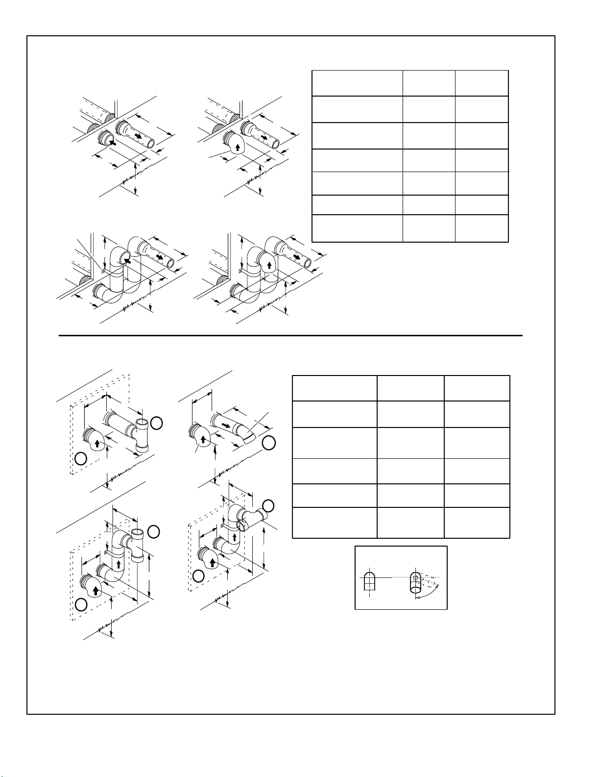
NOTE − FIELD−PROVIDED
REQUIRED TO ADAPT
LARGER VENT PIPE SIZE
* WALL
SUPPORT
C1
REDUCER MAY BE
TO TERMINATION
C1
A
E
D
B
Intake
Elbow
STRAIGHT
APPPLICATION
D
B
A
EXTENDED
APPLICATION
FIELD FABRICATED WALL TERMINATION
A− Minimum clearance
above grade or average
snow accumulation
B− Maximum horizontal
separation between
intake and exhaust
C1 -Minimum from end of
exhaust to inlet of intake
C2 -Minimum from end of
exhaust to inlet of intake
D− Maximum exhaust
pipe length
E− Maximum wall support
distance from top of each
pipe (intake/exhaust)
D
B
* Use wall support every 24” (610 mm). Use two
wall supports if extension is greater than
24” (610 mm) but less than 48” (1219 mm).
NOTE − One wall support must be within 6” (152 mm)
from top of each pipe (intake and exhaust) to prevent
movement in any direction.
C2
D
B
C2
A
E
A
2” (51mm)
Vent Pipe
12” (305 mm)
12” (305 mm)
3” (76mm)
Vent Pipe
12” (305 mm)
6” (152 mm)6” (152 mm)
8” (203 mm)8” (203 mm)
6” (152 mm)6” (152 mm)
20” (508 mm)
6” (152 mm)6” (152 mm)
ALTERNATE TERMINATIONS (TEE & FORTY−FIVE DEGREE ELBOWS ONLY)
2” (51MM)
Vent Pipe
12” (305 mm) Min. 12” (305 mm) Min.
6” (152 mm) Min.
24” (610 mm) Max.
9” (227 mm) Min.
12” (305 mm) Min.
16” (405 mm) Max.
6” (152 mm) Max.
Front View of
Intake and Exhaust
Intake
Exhaust
Intake
Elbow
B
C
Exhaust
D
3
A
D
E
B
C
1
12”
A− Clearance above
grade or average snow
accumulation
B− Horizontal
separation between
intake and exhaust
C− Minimum from
end of exhaust to
inlet of intake
D− Exhaust pipe length
E− Wall support distance
from top of each pipe
(intake/exhaust)
2
A
D
B
1
C
2
A
D
E
B
C
1
12”
2
A
1
The exhaust termination tee should be connected to the 2” or 3” PVC flue pipe as shown in the illustration.
Do not use an accelerator in applications that include an exhaust termination tee.
The accelerator is not required.
2
As required. Flue gas may be acidic and may adversely affect some building materials. If a side wall vent
termination is used and flue gases will impinge on the building materials, a corrosion-resistant shield
(24 inches square) should be used to protect the wall surface. If optional tee is used, the protective shield
is recommended. The shield should be constructed using wood, sheet metal or other suitable material.
All seams, joints, cracks, etc. in affected area, should be sealed using an appropriate sealant.
3
Exhaust pipe 45° elbow can be rotated to the side away from the combustion air inlet to direct exhaust
away from adjacent property. The exhaust must never be directed toward the combustion air inlet.
3” (76MM)
Vent Pipe
6” (152 mm) Min.
24” (610 mm) Max.
9” (227 mm) Min.
12” (305 mm) Min.
20” (508 mm) Max.
6” (152 mm) Max.
Figure 38. Field Supplied Wall Termination
508405-01Page 28 of 53 Issue 2332
Page 29
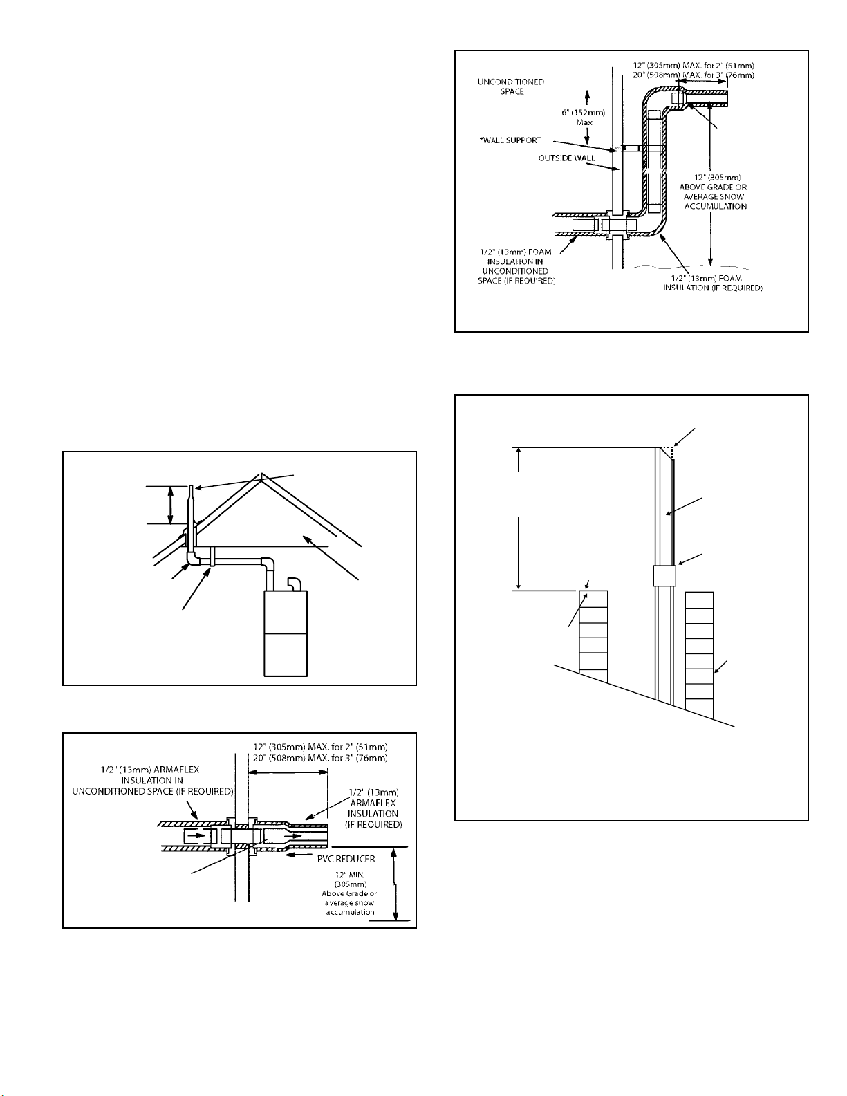
Details of Exhaust Piping Terminations for Non-
Direct Vent Applications
Exhaust pipe may be routed either horizontally through
an outside wall or vertically through the roof. In attic or
closet installations, vertical termination through the roof
is preferred. Figure 39 through Figure 42 show typical
terminations.
1. Exhaust piping must terminate straight out or up as
shown. The termination pipe must be sized as listed
in Table 9. The specied pipe size ensures proper
velocity required to move the exhaust gases away
from the building.
2. On eld supplied terminations for side wall exit,
exhaust piping may extend a maximum of 12 inches
(305 mm) for 2” PVC and 20” (508 mm) for 3” (76 mm)
PVC beyond the outside wall. See Figure 40.
3. If exhaust piping must be run up a sidewall to position
above snow accumulation or other obstructions, piping
must be supported every 24” (610 mm) as shown in
Figure 41. When exhaust piping must be run up an
outside wall, any reduction in exhaust pipe size must
be done after the nal elbow.
SIZE TERMINATION
PER EXHAUST PIPE
TERMINATION SIZE
REDUCTION TABLE
FIELD-PROVIDED
REDUCER MAY BE
REQUIRED TO
ADAPT DIFFERENT
VENT PIPE SIZE TO
TERMINATION
* Use wall support every 24” (610 mm). Use two supports of extension is greater than 24”
(610 mm) but less than 48” (1219 mm).
Figure 41. Non-Direct Vent Field Supplied Wall
Termination - Extended
* SIZE TERMINATION PIPE PER EXHAUST
PIPE TERMINATION SIZE REDUCTION TABLE
STRAIGHT-CUT OR
ANGLE-CUT IN DIRECTION
OF ROOF SLOPE *
SIZE PER EXHAUST PIPE
12” (305MM)
ABOVE AVE.
SNOW
ACCUMULATION
3” (76MM) OR
2” (51MM) PVC
PROVIDE SUPPORT
FOR EXHAUST LINES
TERMINATION SIZE
REDUCTION TABLE
UNCONDITIONED
ATTIC SPACE
Figure 39. Non-Direct Vent Roof Termination Kit
FIELD-PROVIDED
REDUCER MAY BE
REQUIRED TO
ADAPT DIFFERENT
VENT PIPE SIZE TO
TERMINATION
SIZE TERMINATION
PER EXHAUST PIPE
TERMINATION SIZE
REDUCTION TABLE
Minimum 12” (305mm)
above chimney top
plate or average snow
accumulation
INTAKE PIPE
INSULATION (optional)
METAL TOP
INSULATE
TO FORM
SEAL
SHEET
PLATE
EXHAUST VENT
1/2” (13mm)
WEATHERPROOF
INSULATION
SHOULDER OF FITTINGS
PROVIDE SUPPORT
OF PIPE ON TOP PLATE
EXTERIOR
PORTION OF
CHIMNEY
NOTE: Do not discharge exhaust gases directly into any
chimney or vent stack. If vertical discharge through an existing
unused chimney or stack is required, insert piping inside
chimney until the pipe open end is above top of chimney and
terminate as illustrated. In any exterior portion of chimney, the
exhaust vent must be insulated.
Figure 42. Non-Direct Vent Application Using Existing
Chimney
Figure 40. Non-Direct Vent Field Supplied Wall
Termination
508405-01 Page 29 of 53Issue 2332
Page 30
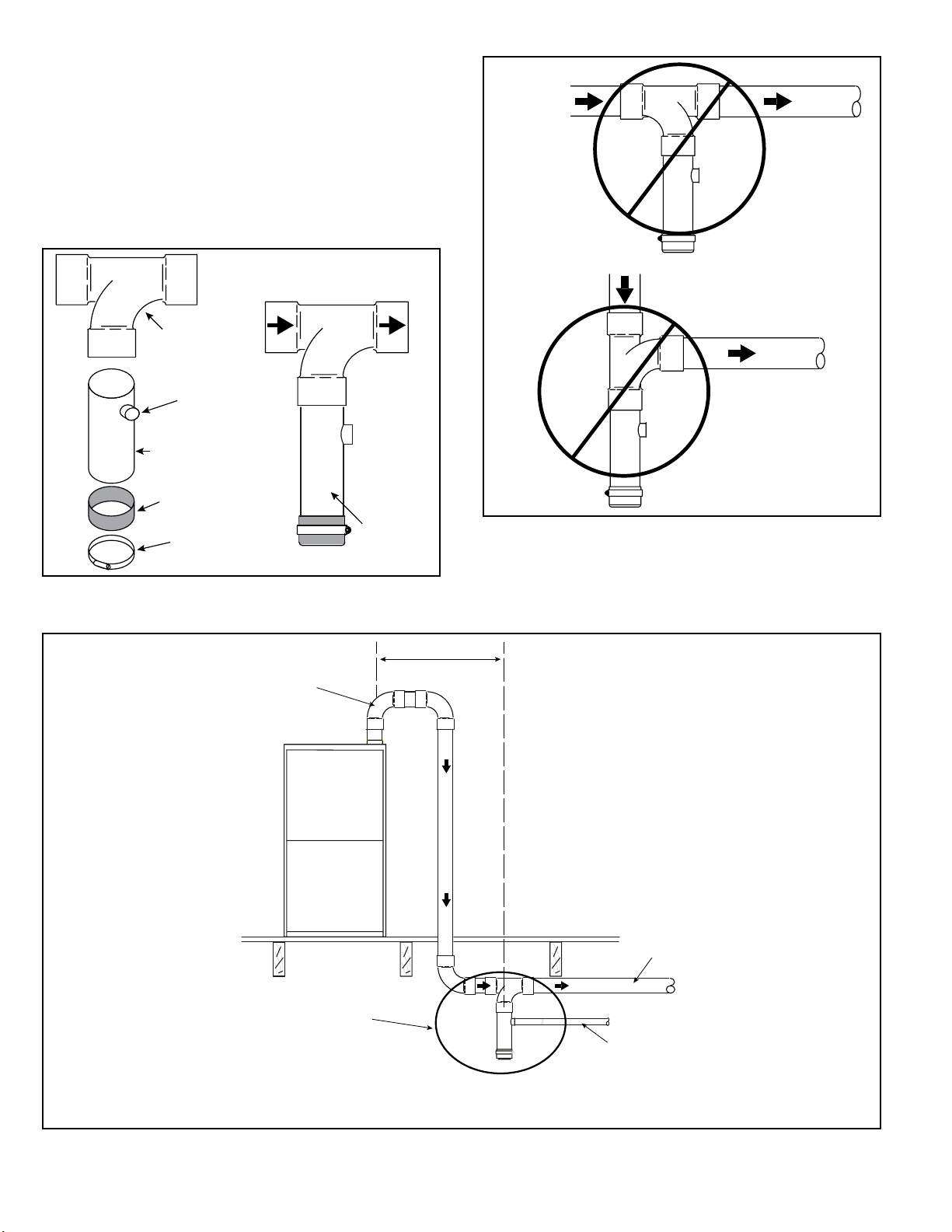
Exhaust through Crawl Space Vent Option
All 33” condensing gas furnaces (92%+) are now approved
to be vented down through a crawl space. Ensure a vent
pipe drain kit, 51W18 (USA) or 15Z70 (Canada), is used as
directed through the oor joists and into the crawl space.
See the following gures.
Consult the vent tables for vent lengths and approved
materials.
From
Furnace
2” or 3”
Sanitary Tee
1/2” PVC
Drain Stub
Drain Trap
Assembly
Rubber Boot (51W18)
Drain Plug (15Z70)
Clamp
(51W18 Only)
To Vent
Termination
Drain Trap
(assembled)
Exhaust from
Furnace
To Termination
Exhaust from
Furnace
To Termination
* Kit 51W18 is shown.
Figure 44. Crawl Space Vent Pipe Drain Trap
Assembled Incorrectly
Figure 43. Kit 51W18 (USA) / 15Z70 (Canada) Parts
Identication and Assembly
Downflow Furnace
Exhaust
KIT 51W18 (USA)
KIT 15Z70 (Canada)
24” max.
* Kit 51W18 is shown.
Basement Floor
To Termination
1/2” PVC to
Code-Approved
Drain
NOTE: Upow furnaces exhaust from the left side. All dimensions shown are typical for upow or downow furnaces.
NOTE: All horizontal runs of exhaust pipe must slope back toward the kit a minimum of 1/4” (6mm) for each 12” (305mm) to ensure drainage.
Figure 45. Upow or Downow Furnace with Exhaust through Crawl Space
508405-01Page 30 of 53 Issue 2332
Page 31
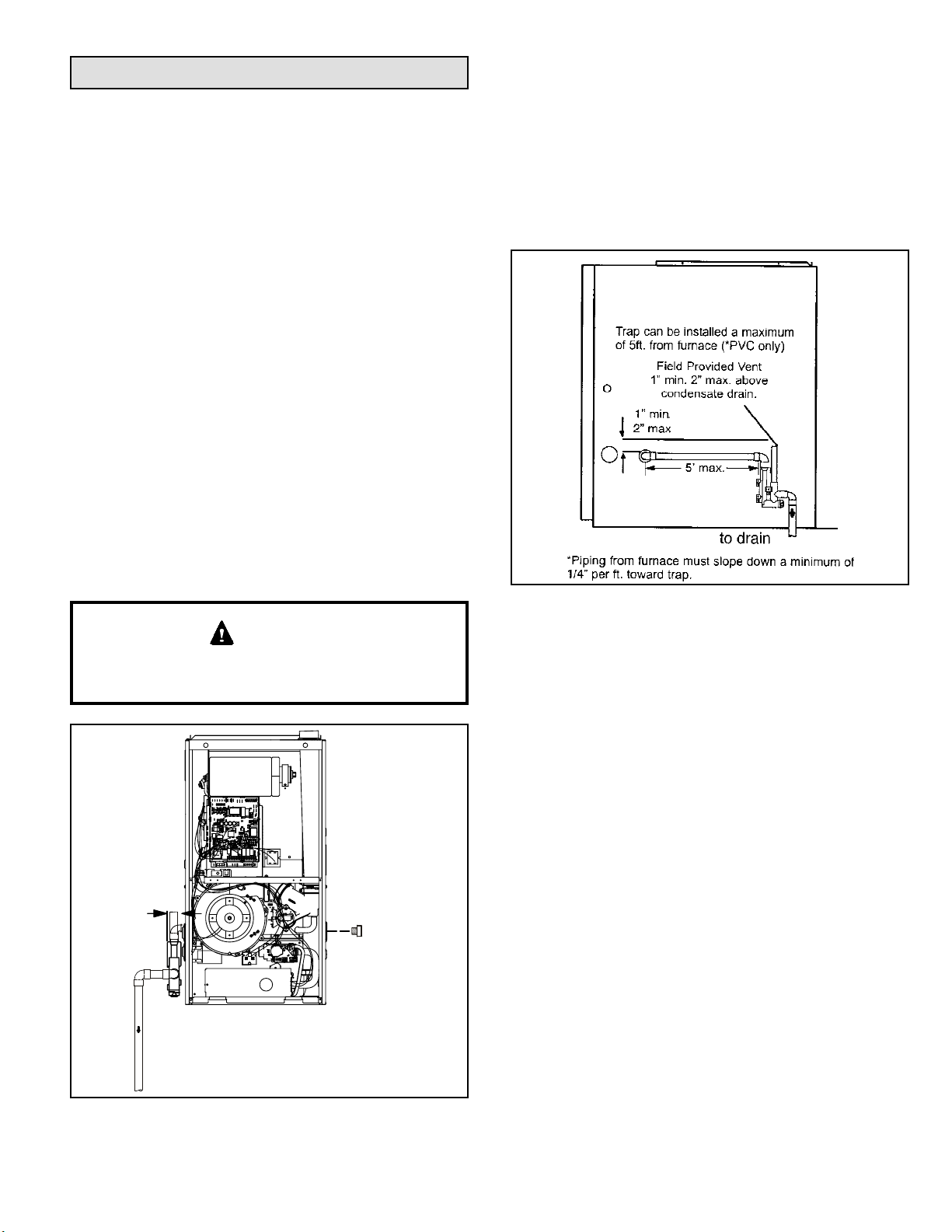
Condensate Piping
This unit is designed for either right or left side exit of
condensate piping in downow applications. Refer to
Figure 46 for condensate trap locations.
NOTE: If necessary the condensate trap may be installed
up to 5 feet away using PVC pipe from the furnace. Piping
from furnace must slope down a minimum of 1/4” per ft.
toward trap.
1. Determine which side condensate piping will exit the
unit, location of trap, eld-provided ttings and length
of PVC pipe required to reach available drain.
2. Use a large at head screw driver or a 1/2” drive
socket extension and remove plug (Figure 46) from
the cold end header box at the appropriate location
on the side of the unit. Install provided 3/4 NPT street
elbow tting into cold end header box. Use Teon tape
or appropriate pipe dope.
3. Install the cap over the clean out opening at the base
of the trap. Secure with clamp. See Figure 51.
4. Install drain trap using appropriate PVC ttings, glue
all joints. Glue the provided drain trap as shown in
Figure 51. Route the condensate line to an open drain.
Condensate line must maintain a 1/4” downward slope
from the furnace to the drain.
NOTE: Vinyl tubing may be used for condensate drain.
Tubing must be 1-1/4” OD x 1” ID and should be attached
to the drain on the trap using a hose clamp.
5. Figure 48 shows the furnace and evaporator coil
using a separate drain. If necessary, the condensate
line from the furnace and evaporator coil can drain
together. See Figure 49. The eld provided vent must
be a minimum 1” to a maximum 2” length above the
condensate drain outlet connection.
CAUTION
Do Not use copper tubing or existing copper condensate
lines for drain line.
Trap
(same on
right side)
1-1/2 in.
Plug
(same on
left side)
Figure 47. Condensate Trap Location
(shown with right side exit of condensation)
6. If unit will be started immediately upon completion of
installation, prime trap per procedure outlined in Unit
Start-Up section.
Condensate line must slope downward away from the
trap to drain. If drain level is above condensate trap,
condensate pump must be used. Condensate drain line
should be routed within the conditioned space to avoid
freezing of condensate and blockage of drain line. If
this is not possible, a heat cable kit may be used on the
condensate trap and line. Heating cable kit is available in
various lengths; 6 ft. (1.8 m) - kit no. 26K68; 24 ft. (7.3 m) kit no. 26K69; and 50 ft. (15.2 m) - kit no. 26K70.
Figure 46. Condensate Trap and Plug Locations
508405-01 Page 31 of 53Issue 2332
Page 32
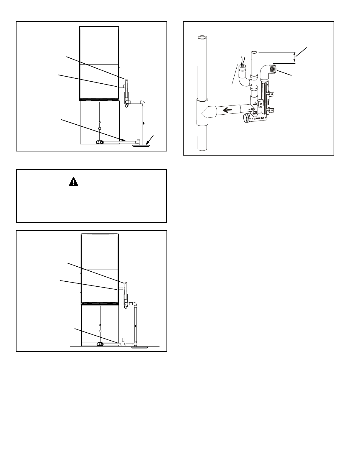
Field Provided Vent
1” min. 2” max. above
condensate drain.
Condensate
Drain Connection
Evaporator Drain Line
(vent required)
Drain
From Evaporator Coil
Optional
Overflow Switch
Field-Provided Vent
(Upflow Furnace 1” Min. to 2” Max.
Horizontal Furnace 4” Min. to 5” Max.
above condensate drain connection)
Furnace Condensate
Drain Connection
Figure 48. Evaporator Coil Using a Separate Drain
CAUTION
When combining the furnace and evaporator coil
drains together, the A/C condensate drain outlet must
be vented to relieve pressure in order for the furnace
pressure switch to operate properly.
Field Provided Vent
1” min. 2” max. above
condensate drain.
Condensate
Drain Connection
Evaporator Drain Line
(vent required)
Figure 50. Condensate Trap with Optional Overow
Switch
Figure 49. Evaporator Coil Using a Common Drain
508405-01Page 32 of 53 Issue 2332
Page 33
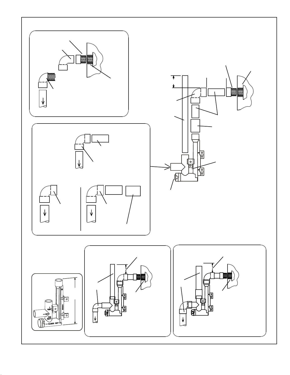
Optional Condensate Drain Connection
Adapter 3/4 inch slip X
3/4 inch mpt (not furnished)
90° Street Elbow
3/4 inch PVC
(not furnished)
Condensate Drain
Connection In Unit
90° Street Elbow
3/4 inch PVC
( furnished)
To
Trap
Optional Drain Piping From Tr ap
Drain Assembly for 1/2 inch Drain Pipe
1/2 inch PVC Pipe
(Not Furnished)
90° Elbow
1/2 inch PVC
(Not Furnished)
To
Drain
Drain Assembly for 3/4 inch Drain Pipe
1(25 mm) Min.
2 (50 mm) Max.
AboveTop Of
Condensate Drain
Connection In Unit
Elbow 3/4 inch PVC
90°
(Not Furnished)
1/2 inch PVC Pipe
(Not Furnished)
Adapter 3/4 inch slip X
3/4 inch mpt (not furnished)
V
ent
5 Feet
Maximum
3/4 inch PVC Pipe
(Not Furnished)
Coupling 3/4 inch slip X slip
(Not Furnished)
Drain Trap
Assembly
(Furnished)
Condensate Drain
Connection In Unit
90° Elbow
3/4 inch PVC
(Not Furnished)
To
Drain
DrainTr ap Assembly
(Furnished)
7
(178)
Drain Trap
Clean Out
90° Elbow
3/4 inch PVC
(Not Furnished)
o
T
Coupling 3/4 inch slip X slip
Drain
DrainTr ap Assembly with 1/2 inch Piping
1 (25 mm) Min. 2 (50 mm) Max. AboveTop
Of Condensate Drain Connection In Unit
(Not Furnished)
Vent
1/2 inch
Condensate Drain
Connection In Unit
To
Drain
DrainTr ap Assembly with 3/4 inch Piping
1 (25 mm) Min. 2 (50 mm) Max. AboveTop
Of Condensate Drain Connection In Unit
Vent
3/4 inch
Condensate Drain
Connection In Unit
To
Drain
Figure 51. Trap Drain Assembly Using 1/2” PVC or 3/4” PVC
508405-01 Page 33 of 53Issue 2332
Page 34
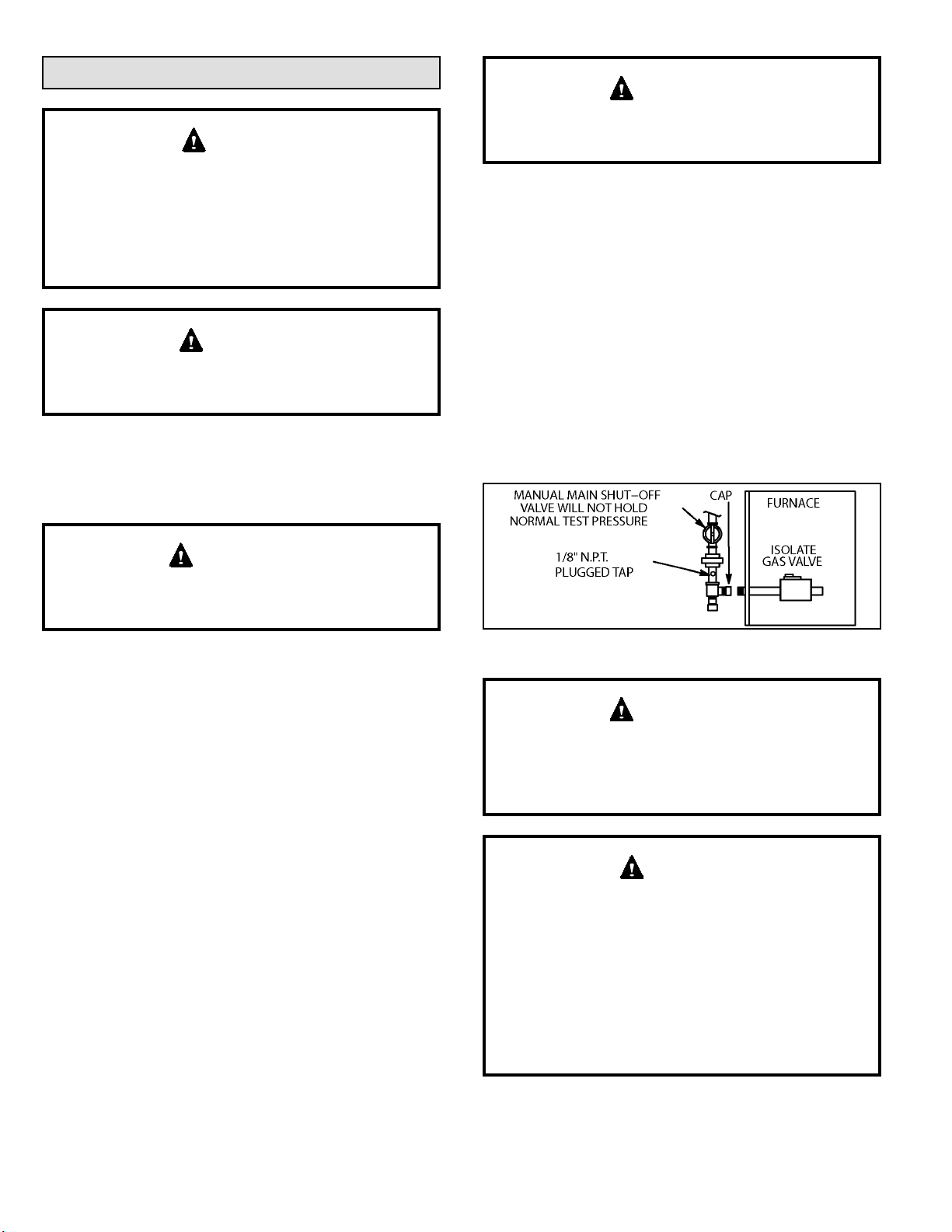
Gas Piping
CAUTION
If a exible gas connector is required or allowed by
the authority that has jurisdiction, black iron pipe shall
be installed at the gas valve and extend outside the
furnace cabinet. The exible connector can then be
added between the black iron pipe and the gas supply
line.
WARNING
Do Not exceed 600 in. lbs. (50 ft. lbs.) torque when
attaching the gas piping to the gas valve.
1. Gas piping may be routed into the unit through either
the left or right hand side. Supply piping enters into
the gas valve from the side of the valve as shown in
Figure 53.
IMPORTANT
Compounds used on threaded joints of gas piping must
be resistant to the actions of liquied petroleum gases.
Leak Check
After gas piping is completed, carefully check all eld-
installed piping connections for gas leaks. Use a
commercially available leak detecting solution specically
manufactured for leak detection. Never use an open ame
to test for gas leaks.
The furnace must be isolated from the gas supply
system by closing the individual manual shut-o valve
during any gas supply system at pressures greater than
or equal to 1/2 psig (3.48 kPa, 14 inches w.c.). This
furnace and its components are designed, manufactured
and independently certied to comply with all applicable
ANSI/CSA standards. A leak check of the furnace and its
components is not required.
IMPORTANT
A low inlet pressure switch in LP/propane applications
is recommended.
2. When connecting gas supply, factors such as length
of run, number of ttings and furnace rating must be
considered to avoid excessive pressure drop. Table 10
lists recommended pipe sizes for typical applications.
NOTE: Use two wrenches when connecting gas piping
to avoid transferring torque to the manifold.
3. Gas piping must not run in or through air ducts,
clothes chutes, chimneys or gas vents, dumb waiters
or elevator shafts. Center gas line through piping hole.
Gas line should not touch side of unit. See Figure 53.
4. Piping should be sloped 1/4 inch per 15 feet (6 mm per
5.6 m) upward toward the gas meter from the furnace.
The piping must be supported at proper intervals,
every 8 to 10 feet (2.44 to 3.05 m), using suitable
hangers or straps. Install a drip leg in vertical pipe runs
to serve as a trap for sediment or condensate.
5. A 1/8” N.P.T. plugged tap or pressure post is located
on the gas valve to facilitate test gauge connection.
6. In some localities, codes may require installation of a
manual main shut o valve and union (furnished by
installer) external to the unit. Union must be of the
ground joint type.
Figure 52.
IMPORTANT
When testing pressure of gas lines, gas valve must
be disconnected and isolated. Gas Valves can be
damaged if subjected to pressures greater than 1/2 psig
(3.48 kPa).
WARNING
FIRE OR EXPLOSION HAZARD
Failure to follow the safety warnings exactly could
result in serious injury, death, or property damage.
Never use an open ame to test for gas leaks. Check
all connections using a commercially available soap
solution made specically for leak detection. Some
soaps used for leak detection are corrosive to certain
metals. Carefully rinse piping thoroughly after leak test
has been completed.
508405-01Page 34 of 53 Issue 2332
Page 35
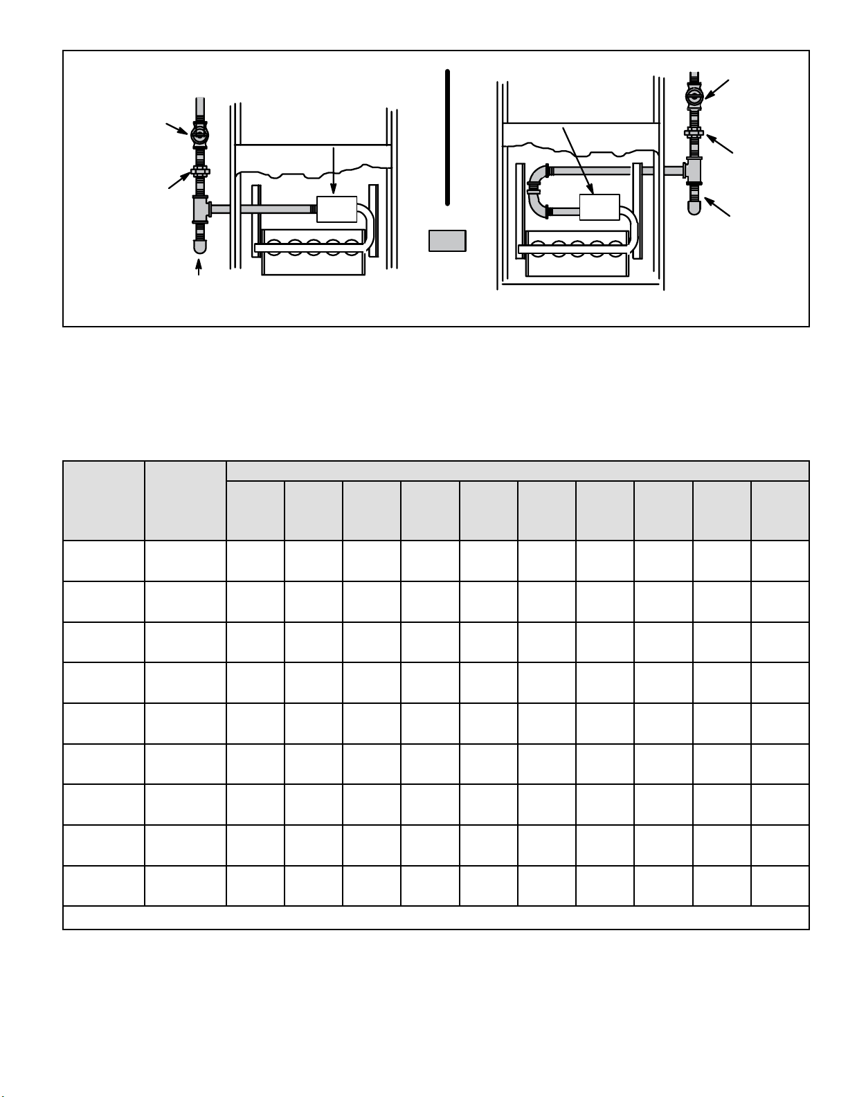
MANUAL
MAIN SHUT-OFF
VALV E
(With 1/8 in. NPT
Plugged Tap Shown)
GROUND
JOINT
UNION
Left Side Piping
(Standard)
AUTOMATIC
GAS VALV E
(with manual
shut-off valve)
AUTOMATIC
GAS VALV E
(with manual
shut-off valve)
MANUAL
MAIN SHUT-OFF
VALV E
(With 1/8 in. NPT
Plugged Ta p
Shown)
GROUND
JOINT
UNION
DRIP LEG
Right Side Piping
DRIP LEG
FIELD
PROVIDED
AND INSTALLED
NOTE - BLACK IRON PIPE ONLY TO BE ROUTED INSIDE OF CABINET
Figure 53.
Gas Pipe Capacity - FT³/HR (kL/HR)
Nominal
Iron Pipe
Size -
inches
(mm)
1/2
(12.7)
3/4
(19.05)
1
(25.4)
1-1/4
(31.75)
1-1/2
(38.1)
2
(50.8)
2-1/2
(63.5)
3
(76.2)
4
(101.6)
Internal
Diameter
- inches
(mm)
.622
(17.799)
.824
(20.930)
1.049
(26.645)
1.380
(35.052)
1.610
(40.894)
2.067
(52.502)
2.469
(67.713)
3.068
(77.927)
4.026
(102.260)
10
(3.048)20(6.096)30(9.144)40(12.192)50(15.240)60(18.288)70(21.336)80(24.384)90(27.432)
175
(4.96)
360
(10.19)
680
(19.25)
1400
(39.64)
2100
(59.46)
3950
(111.85)
6300
(178.39)
11000
(311.48)
23000
(651.27)
120
(3.40)97(2.75)82(2.32)73(2.07)66(1.87)61(1.73)57(1.61)53(1.50)50(1.42)
250
(7.08)
465
(13.17)
950
(26.90)
460
(41.34)
2750
(77.87)
4350
(123.17)
7700
(218.03)
15800
(447.39)
200
(5.66)
375
(10.62)
770
(21.80)
1180
(33.41)
2200
(62.30)
3520
(99.67)
6250
(176.98)
12800
(362.44)
NOTE: Capacity given in cubic feet of gas per hour (kilo liters of gas per hour) and based on 0.60 specic gravity gas.
Length of Pipe - feet (m)
170
(4.81)
320
(9.06)
660
(18.69)
990
(28.03)
1900
(53.80)
3000
(84.95)
5300
(150.07)
10900
(308.64)
151
(4.28)
285
(8.07)
580
(16.42)
900
(25.48)
1680
(47.57)
2650
(75.04)
4750
(134.50)
9700
(274.67)
138
(3.91)
260
(7.36)
530
(15.01)
810
(22.94)
1520
(43.04)
2400
(67.96)
4300
(121.76)
9700
(274.67)
125
(3.54)
240
(6.80)
490
(13.87)
750
(21.24)
1400
(39.64)
2250
(63.71)
3900
(110.43)
8100
(229.36)
118
(3.34)
220
(6.23)
460
(13.03)
690
(19.54)
1300
(36.81)
2050
(58.05)
3700
(104.77)
7500
(212.37)
(12.18)
(18.41)
(34.55)
(55.22)
(97.69)
(203.88)
(Alternate)
110
(3.11)
205
(5.80)
430
650
1220
1950
3450
7200
100
(30.480)
103
(2.92)
195
(5.52)
400
(11.33)
620
(17.56)
1150
(32.56)
1850
(52.38)
3250
(92.03)
6700
(189.72)
Table 10.
508405-01 Page 35 of 53Issue 2332
Page 36
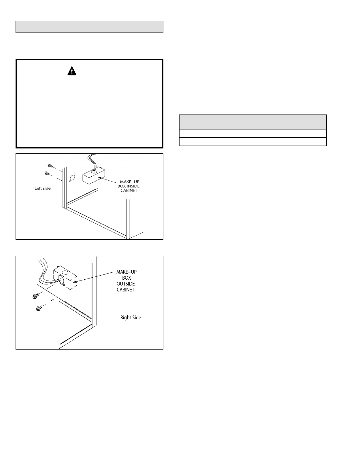
Electrical
ELECTROSTATIC DISCHARGE (ESD)
Precautions and Procedures
CAUTION
Electrostatic discharge can aect electronic components.
Take precautions during furnace installation and service
to protect the furnace’s electronic controls. Precautions
will help to avoid control exposure to electrostatic
discharge by putting the furnace, the control and the
technician at the same electrostatic potential. Neutralize
electrostatic charge by touching hand and all tools on
an unpainted unit surface, such as the gas valve or
blower deck, before performing any service procedure.
Figure 54. Interior Make-Up Box Installation
Figure 55. Interior Make-Up Box Installation
The unit is equipped with a eld makeup box. The makeup
box may be installed on the exterior of the right side of
the furnace to facilitate installation. Seal unused openings
on left side with plugs removed from right side. Secure
the excess wire to the existing harness to protect it from
damage.
Refer to Figure 65 for eld wiring and Figure 64 for
schematic wiring diagram and troubleshooting.
1. The power supply wiring must meet Class I restrictions.
Protected by either a fuse or circuit breaker, select
circuit protection and wire size according to unit
nameplate.
NOTE: Unit nameplate states maximum current draw.
Maximum over current protection allowed is shown in
Table 11.
2. Holes are on both sides of the furnace cabinet to
facilitate wiring.
3. Install a separate (properly sized) disconnect switch
near the furnace so that power can be turned o for
servicing.
Capacity
070 15
090, 110 20
Maximum Over-Current
Protection (Amps)
Table 11.
4. Before connecting the thermostat, check to make sure
the wires will be long enough for servicing at a later
date. Make sure that thermostat wire is long enough to
facilitate future removal of blower for service.
5. Complete the wiring connections to the equipment.
Use the provided unit wiring diagram and the eld
wiring diagram shown in Figure 64. Use 18 gauge
wire or larger that is suitable for Class II rating for
thermostat connections.
6. Electrically ground the unit according to local codes or,
in the absence of local codes, according to the current
National Electric Code (ANSI/NFPA No. 70). A green
ground wire is provided in the eld make-up box.
NOTE: This furnace contains electronic components
that are polarity sensitive. Make sure that the furnace
is wired correctly and is properly grounded.
7. One line voltage “ACC” 1/4” spade terminal is provided
on the furnace integrated control. Any electronic air
cleaner or other accessory rated up to one amp can
be connected to this terminal with the neutral leg of the
circuit being connected to one of the provided neutral
terminals. This terminal is energized when the indoor
blower is operating.
8. One line voltage “HUM” 1/4” spade terminal is provided
on the furnace integrated control. Any humidier rated
up to one amp can be connected to this terminal
with the neutral leg of the circuit being connected to
one of the provided neutral terminals. This terminal
is energized in the heating mode whenever the
combustion air inducer is operating.
9. Install the room thermostat according to the instructions
provided with the thermostat. If the furnace is being
matched with a heat pump, refer to the instruction
packaged with the dual fuel thermostat.
508405-01Page 36 of 53 Issue 2332
Page 37
Indoor Blower Speeds
1. When the thermostat is set to “FAN ON,” the indoor
blower will run continuously at approximately 50%
of the second stage cooling speed when there is no
cooling or heating demand. See Table 19 for allowable
continuous circulation speeds.
2. When this unit is running in the heating mode, the
indoor blower will run on the heating speed designated
by the positions of DIP switches 1 (A,B,C,D) of the
HEAT jumper plug. When the heat demand is satised,
the indoor blower will continue to run at the low stage
heat cfm for the duration of the user-selected heat
blower o delay. The user can select one of the four
preset heat blower o delays (60/90/120/180 sec) by
repositioning the movable shunt on the 5-pin header
on the ignition control.
Electrical Wiring
WARNING
Risk of electrical shock. Disconnect electrical power
at the circuit breaker or service panel before making
electrical connections. Failure to disconnect power
supplies can result in property damage, personal injury,
or death.
The furnace must be grounded and wired in accordance
with local codes or, in the absence of local codes, with the
National Electrical Code ANSI/NFPA No. 70 (latest edition)
and/or CSA C22.1 Electrical Code (latest edition) if an
external electrical source is utilized.
60
Heat Blower OFF
Delay Moveable
90
Shunt
P4
120
180
Figure 56. Heat Blower O Delay Moveable Shunt
3. When there is a cooling demand, the indoor blower will
run on the cooling speed designated by the positions
of DIP switches (A, B, C, D) of the COOL jumper plug.
See Figure 58.
Generator Use - Voltage Requirements
The following requirements must be kept in mind when
specifying a generator for use with this equipment:
• The furnace requires 120 volts ± 10% (Range: 108
volts to 132 volts).
• The furnace operates at 60 Hz ± 5% (Range: 57 Hz
to 63 Hz).
• The furnace integrated control requires both polarity
and proper ground. Both polarity and proper grounding
should be checked before attempting to operate the
furnace on either permanent or temporary power.
• Generator should have a wave form distortion of less
than 5% THD (Total Harmonic Distortion).
In all instances, other than wiring for the thermostat,
the wiring to be done and any replacement of wire shall
conform with the temperature limitation for Type T wire
–63°F (35°C) rise.
Connect a suciently sized wire with ground to the
furnace’s line voltage connections and ground wire. Refer
to the furnace rating plate for electrical characteristics
to be used in sizing eld supply wiring and overcurrent
protection.
The line voltage supply should be routed through a readily
accessible disconnect located within sight of the furnace. A
junction box on the furnace side panel is provided for line
voltage connections. Refer to the furnace wiring diagram
for specic connection information.
Proper polarity of the supply connections (“HOT” and
“NEUTRAL”) must be observed to ensure that safety
controls provide the protection intended.
A connection to the unit’s ground wire and actual earth
ground (typically a ground stake or buried steel pipe) must
be maintained for proper operation.
Thermostat
Install a room thermostat according to the instructions
furnished with it. Select a location on an inside wall that
is not subject to drafts, direct sunshine, or other heat
sources. The initial heat anticipator setting should be equal
to the total current draw of the control circuit. Low voltage
thermostat connections are to be made to the integrated
ignition/blower control board as indicated on the wiring
diagram.
508405-01 Page 37 of 53Issue 2332
NOTE: The automatic heat staging option allows a single
stage thermostat to be used with two stage furnace models.
To activate this option, move the jumper pin (see Figure 57)
to desired setting (5 minutes or 10 minutes). The furnace
will start on 1st stage heat and stay at 1st stage heat for
the duration of the selected time before switching to 2nd
stage heat. W1 on the control board must be connected to
W1 on the thermostat.
Page 38
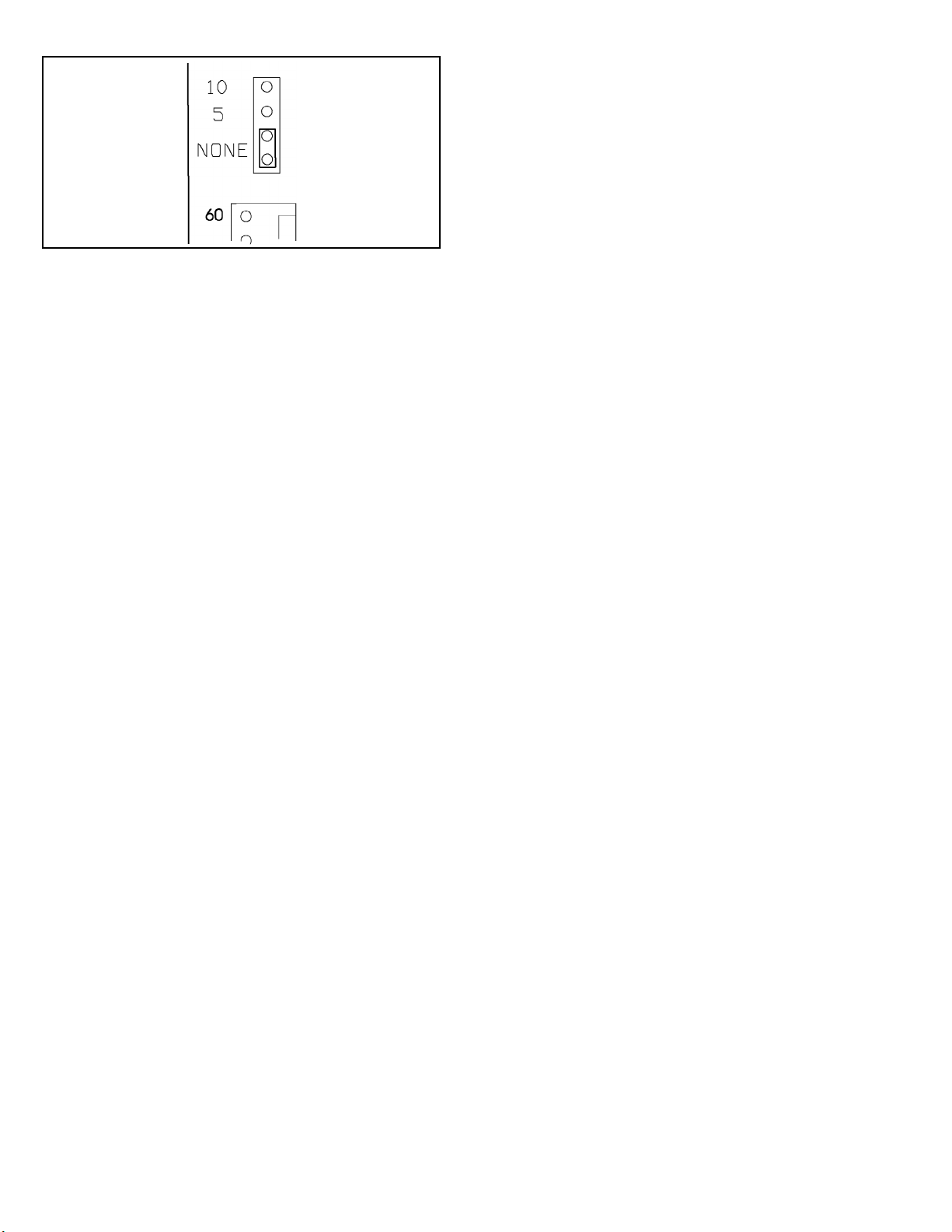
Figure 57. Automatic Heat Staging Jumper
Humidier
Terminals are provided on the integrated ignition/blower
control board for connection to a 120-volt humidier. The
“HUM” terminal is energized whenever the thermostat
calls for heat. See the furnace wiring diagram for specic
connection information.
Electronic Air Cleaner
Terminals are provided on the integrated ignition/blower
control board for connection of a 120-volt electronic air
cleaner. The “ACC” terminal is energized whenever the
thermostat calls for heat, cooling, or continuous blower. See
furnace wiring diagram for specic connection information.
Active Dehumidication
To achieve additional dehumidication, clip the jumper
wire located below the DEHUM terminal on the integrated
ignition/blower control board and connect a humidity
control that opens on humidity rise to the DEHUM and
R terminals. The DEHUM terminal on the control board
must be connected to the normally closed contact of the
humidity control so that the board senses an open circuit
on high humidity. In this setup, the variable speed motor
will operate at a 30% reduction in the normal cooling airow
rate when there is a call for dehumidication.
Both the passive and active dehumidication methods
described above can be utilized on the same furnace.
Circulating Airow Adjustments
Cooling Mode
The units are factory set for the highest airow for each
model. Adjustments can be made to the cooling airow
by repositioning the jumper plug marked COOL – A, B, C,
D (see Figure 58). To determine what CFM the motor is
delivering at any time, count the number of times the amber
LED on the control board ashes. Each ash signies 100
CFM; count the ashes and multiply by 100 to determine
the actual CFM delivered (for example: 10 ashes x 100 =
1000 CFM).
Variable Speed Features
This furnace is equipped with a variable speed circulation
air blower motor that will deliver a constant airow within a
wide range of external static pressures. Other features of
this variable speed motor include:
Soft Start
The variable speed motor will slowly ramp up to normal
operating speed. This minimizes noise and increases
comfort by eliminating the initial blasts of air encountered
with standard motors.
Soft Stop
At the end of a cooling or heating cycle, the variable speed
motor will slowly ramp down after a short blower “o” delay.
If continuous blower operation has been selected, the
variable speed motor will slowly ramp down until it reaches
the airow for that mode.
Passive and Active Dehumidication
Passive Dehumidication
For situations where humidity control is a problem, a
dehumidication feature has been built into the variable
speed motor. At the start of each cooling cycle, the variable
speed motor will run at 82% of the rated airow for 7.5
minutes. After 7.5 minutes has elapsed, the motor will
increase to 100% of the rated airow.
Heating Mode
These units are factory set to run at the middle of the
heating rise range as shown on the unit rating plate. If
higher or lower rise is desired, reposition the jumper plug
marked HEAT - A, B, C, D (see Figure 58) . To determine
what CFM the motor is delivering at any time, count the
number of times the amber LED on the control board
ashes. Each ash signies 100 CFM; count the ashes
and multiply by 100 to determine the actual CFM delivered
(for example: 10 ashes x 100= 1000.
Adjust Tap
Airow amounts may be increased or decreased by 10%
by moving the ADJUST jumper plug (see Figure 58) from
the NORM position to the (+) or (-) position. Changes to the
ADJUST tap will aect both cooling and heating airows.
The TEST position on the ADJUST tap is not used.
Continuous Blower Operation
The comfort level of the living space can be enhanced
when using this feature by allowing continuous circulation
of air between calls for cooling or heating. The circulation
of air occurs at half the full cooling airow rate.
To engage the continuous blower operation, place the
fan switch on the thermostat into the ON position. A call
for fan from the thermostat closes R to G on the ignition
control board. The control waits for a 1 second thermostat
debounce delay before responding to the call for fan by
ramping the circulating blower up to 38% of the cooling
508405-01Page 38 of 53 Issue 2332
Page 39
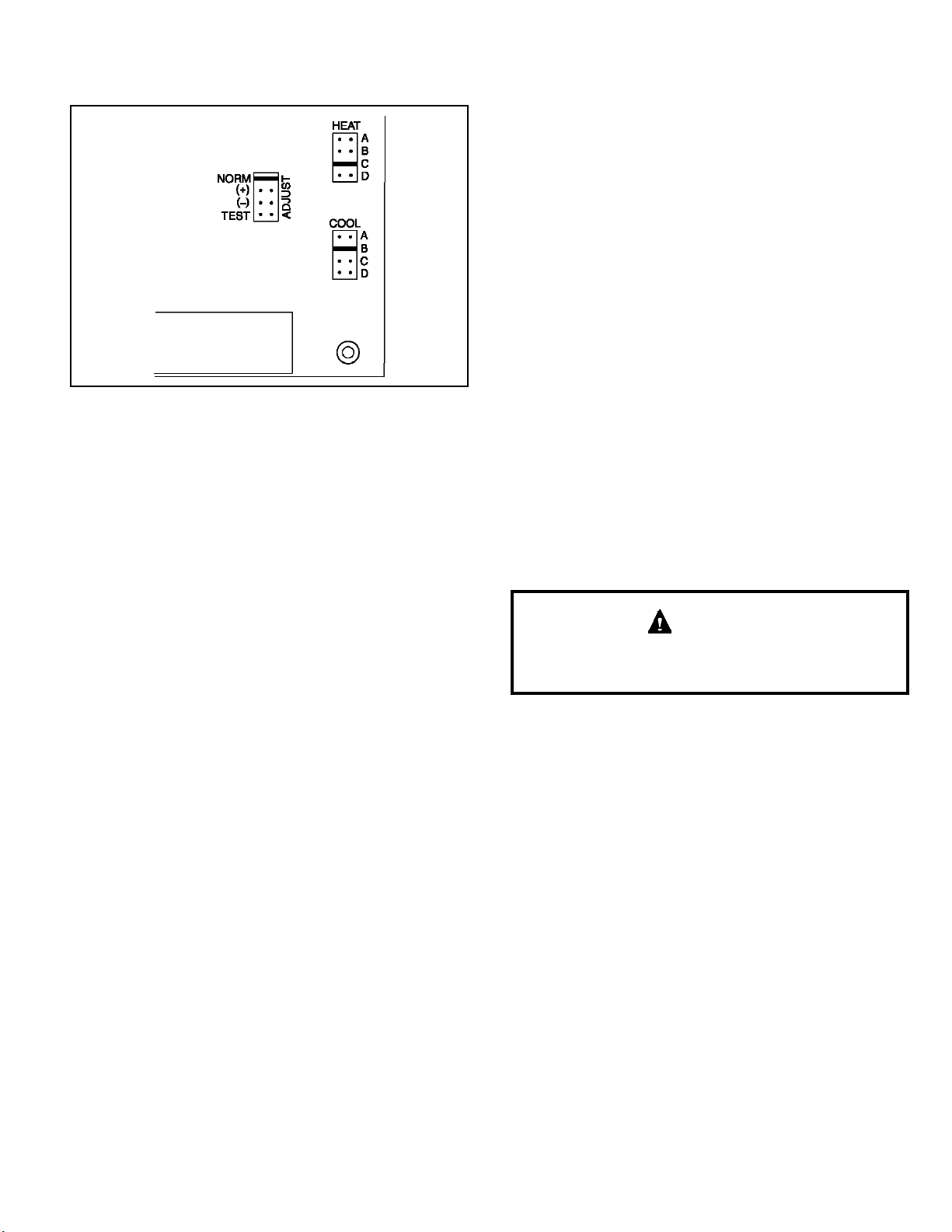
speed. When the call for continuous fan is satised, the
control immediately ramps down the circulating blower.
lockout. Lockout may be manually reset by removing
power from the control for more than 1 second or removing
the thermostat call for heat for more than 3 seconds.
If during a heating cycle the limit control senses an
abnormally high temperature and opens, the control board
de-energizes the gas valve and the combustion blower
while the circulating blower runs at 1st stage heat speed.
The circulating blower remains energized until the limits
are closed.
Fan On
When the thermostat is set for continuous fan operation
and there is no demand for heating or cooling, a call for fan
closes the R to G circuit and the circulating blower motor
runs at 38% of the selected cooling CFM until switched
o. When the call for fan is turned OFF, the control de-
energizes the circulating blower.
Figure 58. ADJUST, HEAT, and COOL Taps on
Integrated Ignition/Blower Control Board
Sequence of Operation
Heating
On a call for heat from the room thermostat, the control
board performs a 1 second self check. Upon conrmation
that the pressure switch contacts are in an open position,
the control energizes the combustion blower on high
speed. The control then checks for adequate combustion
air by making sure the low-re pressure switch contacts
are closed.
The igniter energizes and is allowed to warm up for 20
seconds before the gas valve energizes on 1st stage
and burners ignite. 45 seconds after the control conrms
ignition has occurred, the control drops the combustion
blower to low speed.
The circulating blower operates at full 1st stage heat
speed until either the heat call is satised or the thermostat
initiates a call for 2nd stage heat. On a call for 2nd stage
heat, the control energizes the circulating air blower on full
CFM 2nd stage heat.
If the automatic heat staging option is being used the
furnace does not switch to 2nd stage heat in response
to a call from the thermostat but instead operates at 1st
stage heat for the duration of the selected time before
automatically switching to 2nd stage heat.
When the call for heat is satised, the gas valve and
combustion air blower shut down. The control board shuts
o the gas valve and runs the combustion blower for an
additional 15 seconds. The circulating air blower continues
to run for selected blower o delay time (60/90/120/180
sec) before ramping down and shutting o.
In the event the unit loses ignition, the control will attempt
to recycle up to ve times before it goes into a 1 hour
Cooling
The unit is set up at the factory for single stage cooling. For
two stage cooling operation, clip the jumper wire located
between the Y to Y2 terminals on the integrated ignition/
blower control board.
If the active dehumidication feature is enabled, the
circulating blower runs at 70% of the selected cooling
speed as long as there is a call for dehumidication.
WARNING
The system must not be in either the passive or active
dehumidication mode when charging a cooling system.
Single Stage Cooling
A call for cooling from the thermostat closes the R to Y
circuit on the integrated ignition/blower control board. The
control waits for a 1-second delay before energizing the
circulating blower to 82% of the selected cooling CFM
(passive dehumidication mode). After 7.5 minutes, the
circulating blower automatically ramps up to 100% of
the selected cooling airow. When the call for cooling is
satised, the circulating blower ramps down to continuous
fan cfm (38% of high stage cooling) for 45 seconds before
completely shutting down the blower.
Two Stage Cooling
A call for 1st stage cooling from the thermostat closes the
R to Y circuit on the control board. The control waits for a
1-second delay before energizing the circulating blower.
The blower motor runs at 57% of the selected air ow
for the rst 7.5 minutes of the 2nd stage cooling demand
(passive dehumidication mode). After 7.5 minutes, the
blower motor runs at 70% of the selected cooling air ow
until 1st stage cooling demand is satised.
508405-01 Page 39 of 53Issue 2332
Page 40
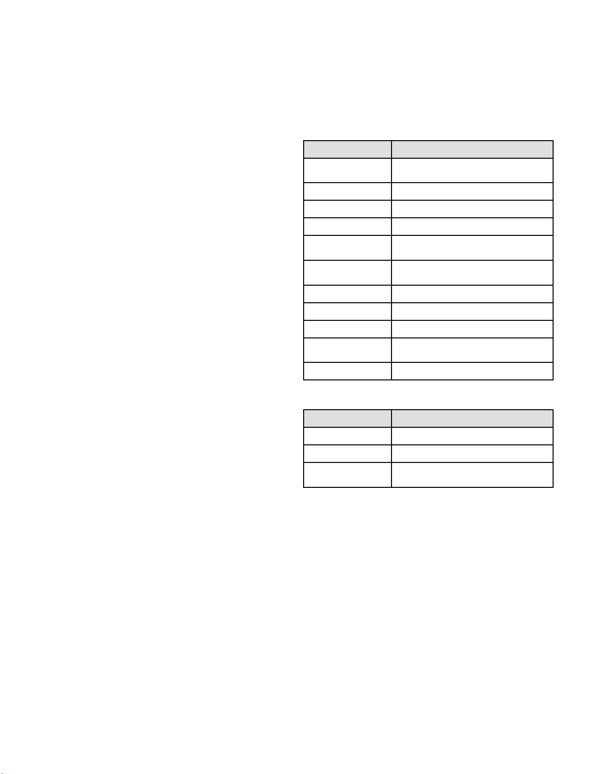
A call for 2nd stage cooling from the thermostat closes
the R to Y2 circuit on the control board. The blower motor
ramps up to 100% of the selected cooling air ow. When
the demand for cooling is met, the blower ramps down
to Y1 until satised, then ramps down to continuous fan
cfm (38% of high stage cooling) for 45 seconds before
completely shutting down the blower.
Heat Pump
For heat pump operation, clip the jumper wire located
below the O terminal on the integrated ignition/blower
control board. In heat pump mode, a call for heat will
result in the circulating air blower operating at the selected
cooling airow after a brief ramp-up period.
Control Diagnostics
Troubleshooting
Make the following visual checks before troubleshooting:
1. Check to see that the power to the furnace and the
integrated ignition/blower control board is ON.
2. The manual shuto valves in the gas line to the furnace
must be open.
3. Make sure all wiring connections are secure.
4. Review the Sequence of Operation.
Start the system by setting thermostat above room
temperature. Observe system response. Then use the
information provided in this section to check the system
operation.
CFM LED
On models equipped with a variable speed motor, an amber
LED is provided on the control board to display CFM. To
determine what CFM the motor is delivering at any time,
count the number of times the amber LED ashes. Each
ash signies 100 CFM; count the ashes and multiply by
100 to determine the actual CFM delivered (for example:
10 ashes x 100 = 1000 CFM).
LED Status Fault Description
LED O
LED On Normal operation
1 Flash Flame present with gas valve o
2 Flashes Pressure switch closed with inducer o
3 Flashes
4 Flashes
5 Flashes Not used
6 Flashes Pressure switch cycle lockout
7 Flashes Lockout due to no ignition
8 Flashes
9 Flashes Incorrect polarity and phasing
No power to control or control
hardware fault detected
Pressure switch open with inducer
energized
Primary Limit, Secondary Limit, or RollOut switch open
Lockout due to too many ame
dropouts
Table 12. Failure Codes - Red LED
The furnace has a built-in, self-diagnostic capability. If a
system problem occurs, a fault code is shown by a red LED
on the control board. The control continuously monitors its
own operation and the operation of the system. If a failure
occurs, the LED will indicate the failure code. The ash
codes are presented in Table 12.
Fault Code History Button
The control stores the last ve fault codes in memory. A
push button switch is located on the control. When the
push button switch is pressed and released, the control
ashes the stored fault codes. The most recent fault code
is ashed rst; the oldest fault code is ashed last. To
clear the fault code history, press and hold the push button
switch in for more than 5 seconds before releasing.
High Heat State LED
On models, a green LED is provided on the control board
to indicate high heat state (see Table 13).
LED Status Description
LED O No demand for high heat
LED On High heat demand, operating normally
LED Flashing
High heat demand, high pressure
switch not closed
Table 13. High Heat State - Green LED
508405-01Page 40 of 53 Issue 2332
Page 41
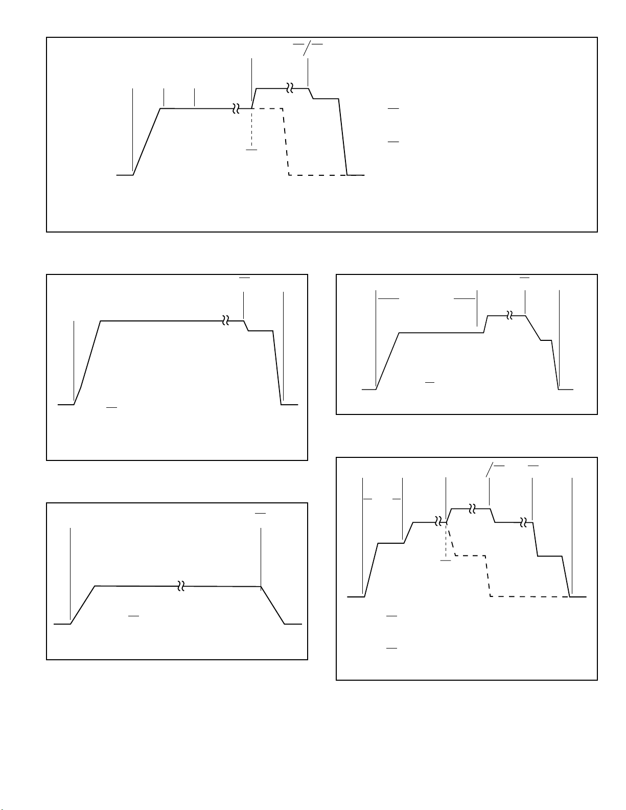
W1/W2
w1 w2
W2
CALL
W1
100%**
100%*
***min
100%*
w1
CALL
*Percentage of Low Fire CFM
** Percentage of High Fire CFM
*** User-Selected Heat Blower OFF Delay
Figure 59. Indoor Blower Operation - 1st Stage-2nd Stage (W1/W2) Heat Call
w2
***min
100%*
W2 - High Heat Demand Present
w2 - High Heat Demand Satisfied
*Percentage of Low Fire CFM
** Percentage of High Fire CFM
*** User-Selected Heat Blower OFF Delay
OFF
***min
100%*
W1 - Heat Demand Present
w1 - Heat Demand Satisfied
W2 - High Heat Demand Present
w2 - High Heat Demand Satisfied
OFF
y
100%*
45
sec
38%
OFF
CALL
Y
7.5 minutes
82%*
Y - Heat Demand Present
y - Heat Demand Satisfied
*Percentage of High Stage Cooling CFM
Figure 62. Indoor Blower Operation - Single Stage
Cooling
Figure 60. Indoor Blower Operation - High Heat (W2)
Call
gG
38%*
G - Fan Switch ON
g - Fan Switch OFF
CALL
*Percentage of High Stage Cooling CFM
Figure 61. Indoor Blower Operation - Call for Fan
OFF
Y1
Y1/Y2
7.5
Y1 y2
100%*
y1
min.
70%*
CALL
57%*
Y1 - 1st Stage Cool Demand Present
y1 - 1st Stage Cool Demand Satisfied
Y2 - 2nd Stage Cooling Demand Present
y2 - 2nd Stage Cooling Demand Satisfied
*Percentage of High Stage Cooling
45 sec
38%*
y1
Figure 63. Indoor Blower Operation - Two Stage
Cooling
70%*
45 sec
38%*
OFF
508405-01 Page 41 of 53Issue 2332
Page 42
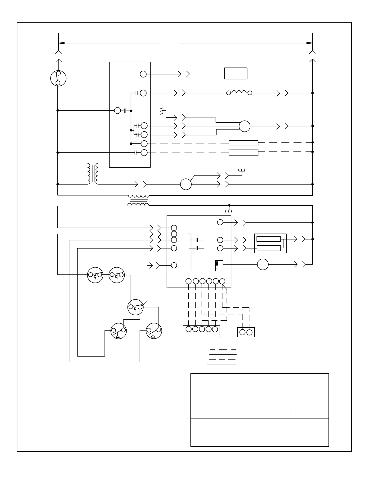
L1 HOT
120/1
NEUTRAL
/60
INTERLOCK
SWITCH
CHOKE
(IF USED)
ROLLOUT
SWITCH
ROLLOUT
SWITCH
(IF USED)
120V
24V
FP
IGN
IND HIGH
IND LOW
HUM
EAC
CIRCULATION
BLOWER
TRANSFORMER
MOTOR
TH
HLO
HPS1
LPS1
HLI
W1
MVH
MVL
IGNITION
CONTROL
W2
C
FLAME
SENSOR
HOT SURFACE
IGNITER
INDUCED DRAFT
BLOWER
MOTOR
HUMIDIFIER
AIR CLEANER
TR
2ND STAGE
1ST STAGE
GAS VALVE
G
Y
R
MOTOR
LIMIT
PRESSURE
SWITCH
(LOW)
WIRING SCHEMATIC
WARNINGELECTRIC SHOCK HAZARD,CAN CAUSE INJURY
OR DEATH.UNIT MUST BE GROUNDED IN ACCORDANCE
WITH NATIONAL AND LOCAL CODES.
NOTEIF ANY WIRE IN THIS APPLIANCE IS REPLACED,IT
MUST BE REPLACED WITH WIRE OF LIKE SIZE,
RATING, INSULATION THICKNESS, AND TERMINATION
Figure 64. Typical Field Wiring Diagram
PRESSURE
SWITCH
(HIGH)
W1W2YR
THERMOSTAT CONDENSER
G
LINE VOLTAGE FIELD INSTALLED
LINE VOLTAGE - FACTORY
CLASS II VOLTAGE FIELD WIRING
LOW VOLTAGE - FACTORY
GAS FIRED TWO STAGE
FURNACE
HEATING UNITS-GAS
Supersedes
508405-01Page 42 of 53 Issue 2332
Page 43
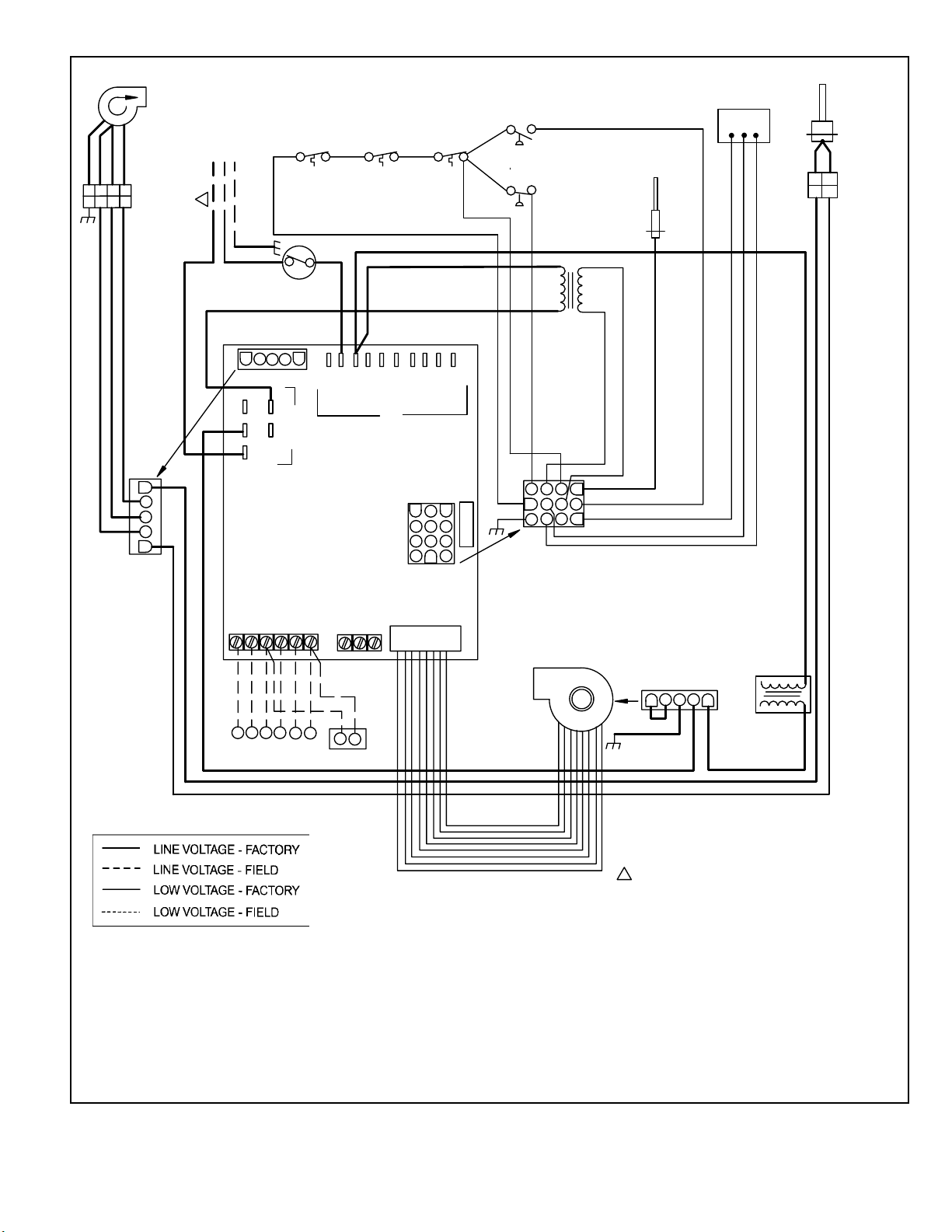
WHITE
GRN/YLW
442
3
WHITE
RED
BLACK
1
3
1
2
RED
BLACK
5 PIN
CONNECTOR
INDUCED
DRAFT
BLOWER
S1
P1
1
2
3
4
5
PRESSURE
SWITCH (HIGH)
LIMIT
PARK 2
HI HEAT
LO HEAT
PINK
PUR
PRESSURE
SWITCH (LOW)
PINK
BLUE
FLAME
SENSOR
BLUE
YELLOW
WHT/PINK
BROWN
BLACK
BLACK
LINE
HUM
ROLLOUT
XFMR
CONT
HOT
EAC
BLUE
BROWN
BLACK
BLACK
COOL
PARK 1
EAC
CIRC
LINE
ROLLOUT
XFMR
HUM
NEUTRAL
HOT
NEUTRAL
GROUND
1
/60
120/1
GRN/YLW
INTERLOCK
SWITCH
WHITE
WHITE
GAS VALVE
PURPLE
H1 C
BROWN
YELLOW
M
ORANGE
2
2
BLACK
HOT SURFACE
IGNITOR
2 PIN
1
CONNECTOR
1
IGNITION
CONTROL
3 AMP
9
12
11
10
3
6
5
8
2
1
4
7
G
W2
W1
W2
W1
THERMOSTAT
YC Y2
R
G
YR
C
0
CONDENSER
DEHUM
WHITE
WHITE
WHITE
CIRCULATION
BLOWER
GRN
5 PIN
CONNECTOR
2345
1
RED
WHITE
BLACK
INPUT CHOKE
(IF USED)
CONNECTION DIAGRAM
1
PROPER POLARITY MUST BE OBSERVED FOR FIELD LINE
VOLTAGE SUPPLY. IGNITION CONTROL WILL LOCK OUT IF
POLARITY IS REVERSED
NOTES:
1. PRESS AND RELEASE FAULT CODE HISTORY BUTTON TO DISPLAY FAULT CODES. TO ERASE CODES, PRESS AND HOLD BUTTON
IN FOR MORE THAN 5 SECONDS
2. IF ANY OF THE ORIGINAL WIRE AS SUPPLIED WITH THE FURNACE MUST BE REPLACED, IT MUST BE REPLACED WITH WIRING
MATERIAL HAVING A TEMP. RATING OF AT LEAST 90°c.
3. DO NOT CONNECT C (COMMON) CONNECTION BETWEEN INDOOR UNIT AND THERMOSTAT EXCEPT WHEN REQUIRED BY THE
INDOOR THERMOSTAT. REFER TO THE THERMOSTAT INSTALLATION INSTRUCTIONS.
Figure 65. Typical Wiring Diagram
508405-01 Page 43 of 53Issue 2332
Page 44
Testing for Proper Venting and Sucient Combustion Air for Non-Direct Vent Applications
1. Seal any unused openings in the venting system.
WARNING
CARBON MONOXIDE POISONING HAZARD
Failure to follow the steps outlined below for each
appliance connected to the venting system being
placed into operation could result in carbon monoxide
poisoning or death.
The following steps shall be followed for each appliance
connected to the venting system being placed into
operation, while all other appliances connected to the
venting system are not in operation.
After the gas furnace has been started, the following
test should be conducted to ensure proper venting and
sucient combustion air has been provided to the unit as
well as to other gas red appliances which are separately
vented.
If this furnace replaces a Category I furnace which was
commonly vented with another gas appliance, the size
of the existing vent pipe for that gas appliance must be
checked. Without the heat of the original furnace ue
products, the existing vent pipe is probably oversized for
the single water heater or other appliance. The vent should
be checked for proper draw with the remaining appliance.
The test should be conducted while all appliances (both
in operation and those not in operation) are connected to
the venting system being tested. If the venting system has
been installed improperly, or if provisions have not been
made for sucient amounts of combustion air, corrections
must be made as outlined in the previous section.
2. Visually inspect the venting system for proper size
and horizontal pitch. Determine there is no blockage
or restriction, leakage, corrosion, or other deciencies
which could cause an unsafe condition.
3. To the extent that it is practical, close all building doors
and windows and all doors between the space in
which the appliances connected to the venting system
are located and other spaces of the building.
4. Close replace dampers.
5. Turn on clothes dryers and any appliances not
connected to the venting system. Turn on any exhaust
fans, such as range hoods and bathroom exhausts, so
they will operate at maximum speed. Do not operate a
summer exhaust fan.
6. Follow the lighting instruction to place the appliance
being inspected into operation. Adjust thermostat so
appliance will operate continuously.
7. Use the ame of a match or candle to test for spillage
of ue gases at the draft hood relief opening after 5
minutes of main burner operation.
8. If improper venting is observed during any of the
above tests, the venting system must be corrected or
sucient combustion/makeup air must be provided.
The venting system should be resized to approach the
minimum size as determined by using the appropriate
tables in appendix G in the current standards of the
National Fuel Gas Code ANSI-Z223.1/NPFA 54 in the
U.S.A., and the appropriate Natural Gas and Propane
appliances venting sizing tables in the current standard
of the CSA-B149 Natural Gas and Propane Installation
Codes in Canada.
9. After determining that each appliance remaining
connected to the common venting system properly
vents when tested as indicated in step 3, return doors,
windows, exhaust fans, replace dampers and any
other gas burning appliance to their previous condition
of use.
508405-01Page 44 of 53 Issue 2332
Page 45
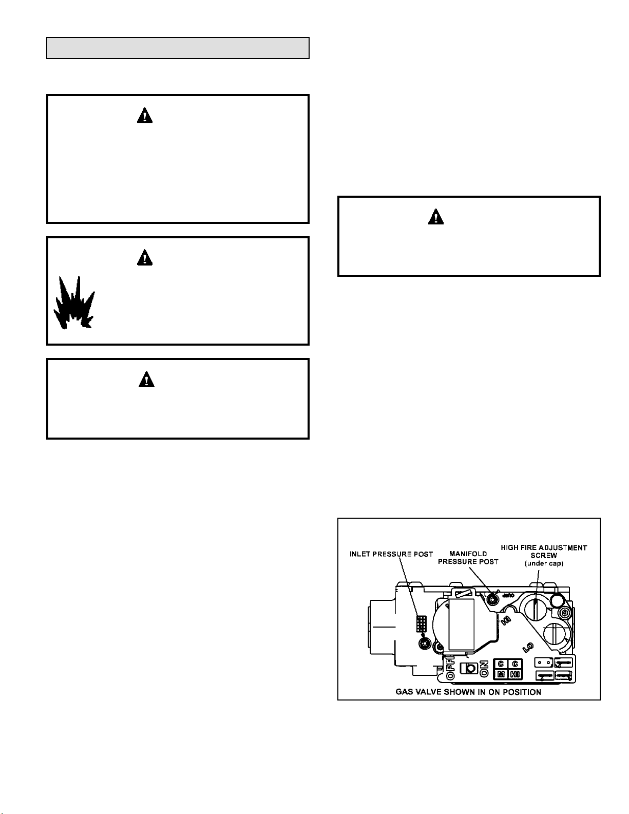
Unit Start-Up
FOR YOUR SAFETY READ BEFORE OPERATING
WARNING
Do not use this furnace if any part has been underwater.
A ood-damaged furnace is extremely dangerous.
Attempts to use the furnace can result in re or explosion.
Immediately call a qualied service technician to inspect
the furnace and to replace all gas controls, control
system parts, and electrical parts that have been wet or
to replace the furnace, if deemed necessary.
WARNING
Danger of explosion. Can cause injury or
product or property damage. Should the gas
supply fail to shut o or if overheating
occurs, shut o the gas valve to the furnace
before shutting o the electrical power.
CAUTION
Before attempting to perform any service or
maintenance, turn the electrical power to unit OFF at
disconnect switch.
BEFORE LIGHTING the unit, smell all around the furnace
area for gas. Be sure to smell next to the oor because
some gas is heavier than air and will settle on the oor.
The gas valve on the unit is equipped with a gas control
switch (lever). Use only your hand to move switch. Never
use tools. If the switch will not move by hand, do not try to
repair it. Force or attempted repair may result in a re or
explosion.
2. Set the thermostat to initiate a heating demand.
3. Allow the burners to re for approximately 3 minutes.
4. Adjust the thermostat to deactivate the heating
demand.
5. Wait for the combustion air inducer to stop. Set the
thermostat to initiate a heating demand and again
allow the burners to re for approximately 3 minutes.
6. Adjust the thermostat to deactivate the heating demand
and wait for the combustion air inducer to stop. At this
point, the trap should be primed with sucient water to
ensure proper condensate drain operation.
WARNING
If you do not follow these instructions exactly, a re
or explosion may result causing property damage,
personal injury or death.
Gas Valve Operation
1. STOP! Read the safety information at the beginning
of this section.
2. Set the thermostat to the lowest setting.
3. Turn OFF all electrical power to the unit.
4. This furnace is equipped with an ignition device which
automatically lights the burners. Do not try to light the
burners by hand.
5. Remove the heating compartment access panel.
6. Move gas valve switch to OFF. See Figure 66.
7. Wait ve minutes to clear out any gas. If you then
smell gas, STOP! Immediately call your gas supplier
from a neighbor’s phone. Follow the gas supplier’s
instructions. If you do not smell gas go to next step.
8. Move gas valve switch to ON. See Figure 66.
Gas Valve Shown In “ON’ Position
Placing the Furnace into Operation
This furnace is equipped with an automatic hot surface
ignition system. Do not attempt to manually light burners
on this furnace. Each time the thermostat calls for heat, the
burners will automatically light. The ignitor does not get hot
when there is no call for heat on these units.
Priming Condensate Trap
The condensate trap should be primed with water prior
to start-up to ensure proper condensate drainage. Either
pour 10 . oz. (300 ml) of water into the trap, or follow
these steps to prime the trap:
1. Follow the lighting instructions to place the unit into
operation.
508405-01 Page 45 of 53Issue 2332
Figure 66.
9. Replace the heating compartment access panel.
10. Turn on all electrical power to the unit.
Page 46
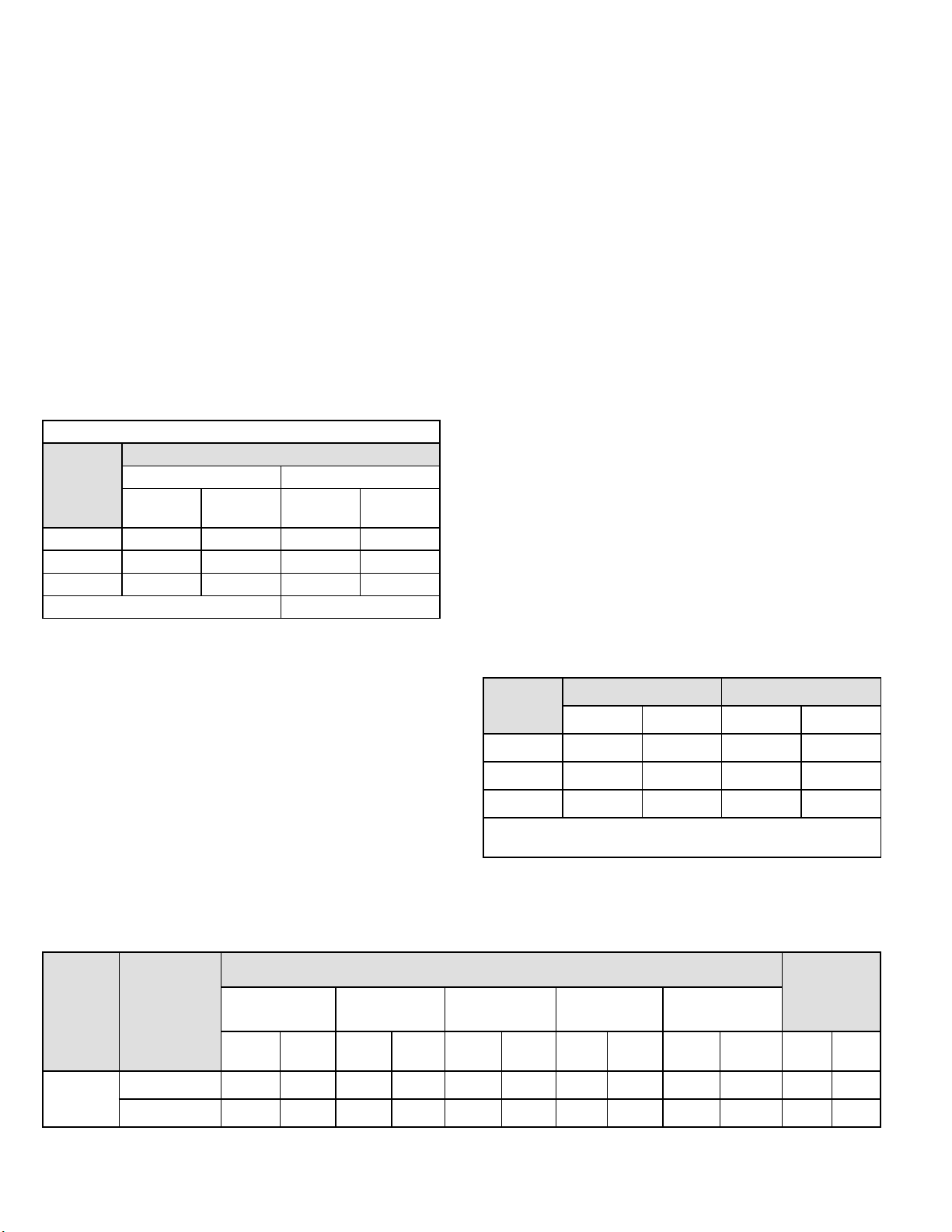
11. Set the thermostat to desired setting.
NOTE: When unit is initially started, steps 1 through
11 may need to be repeated to purge air from gas line.
12. If the appliance will not operate, follow the instructions
“Turning O Gas to Unit” and call your service
technician or gas supplier.
Turning O Gas to Unit
1. Set the thermostat to the lowest setting.
2. Turn o all electrical power to the unit if service is to
be performed.
3. Remove the heating compartment access panel.
4. Move gas valve switch to OFF.
5. Replace the heating compartment access panel.
Gas Pressure Adjustment
Gas Flow (Approximate)
Gas Meter Clocking Chart
Seconds for One Revolution
Capacity
070 55 110 136 272
090 41 82 102 204
110 33 66 82 164
Natural - 1000 btu/cu ft LP - 2500 btu/cu ft
Furnace should operate at least 5 minutes before checking
gas ow. Determine time in seconds for two revolutions of
gas through the meter. (Two revolutions assures a more
accurate time.) Divide by two and compare to time in Table
14. If manifold pressure matches Table 16 and rate is
incorrect, check gas orices for proper size and restriction.
Remove temporary gas meter if installed.
NOTE: To obtain accurate reading, shut o all other gas
appliances connected to meter.
Natural LP
1 cu ft
Dial
2 cu ft
Dial
Table 14.
1 cu ft
Dial
2 cu ft
Dial
one turn, connect a piece of 5/16” tubing and connect a
manometer to measure supply pressure.
NOTE: Shut unit o and remove manometer as soon as
an accurate reading has been obtained. Take care to retighten the 3/32 Hex screw.
Manifold Pressure Measurement
1. A manifold post located on the gas valve provides
access to the manifold pressure. See Figure 66. Back
out the 3/32 Hex screw one turn, connect a piece of
5/16” tubing and connect to a manometer to measure
manifold pressure.
2. Start unit and allow 5 minutes for unit to reach steady
state.
3. While waiting for the unit to stabilize, observe the
ame. Flame should be stable and should not lift from
burner. Natural gas should burn blue.
4. After allowing unit to stabilize for 5 minutes, record
manifold pressure and compare to value given in
Table 16.
NOTE: Shut unit o and remove manometer as soon as
an accurate reading has been obtained. Take care to retighten the 3/32 Hex screw.
Proper Combustion
Furnace should operate minimum 15 minutes with correct
manifold pressure and gas ow rate before checking
combustion. Take combustion sample beyond the ue
outlet and compare to the tables below. The maximum
carbon monoxide reading should not exceed 100 ppm.
CO2% for Nat CO2% for L.P.
Capacity
Low Fire High Fire Low Fire High Fire
070 5.5 - 6.5 7.3 - 8.3 6.5 - 7.5 8.6 - 9.6
090 5.9 - 6.9 7.8 - 8.8 6.9 - 7.9 9.1 - 10.1
110 6.3 - 7.3 8.2 - 9.2 7.3 - 8.3 9.5 - 10.5
The maximum carbon monoxide reading should not exceed
100 ppm.
Supply Pressure Measurement
A pressure post on the inlet side of the gas valve provides
access to the supply pressure. Back out the 3/32 Hex screw
Manifold Pressure in w.g.
Capacity Gas
Natural 1.7 3.5 1.6 3.3 1.5 3.2 1.5 3.1 1.7 3.5 4.5 13.0
All Models
LP/Propane 4.5 10.0 4.2 9.4 4.0 9.1 3.9 8.9 4.5 10.0 11.0 13.0
0 - 4500 ft. 4501 - 5500 ft. 5501 - 6500ft. 6501 - 7500ft. 7501-10000ft.
Low
Fire
High
Fire
Low
Fire
High
Fire
Table 16. Manifold and Supply Line Pressure 0 - 10,000 ft.
Low
Fire
High
Fire
Low
Fire
Table 15.
High
Fire
Low
Fire
High
Fire
Supply Line
Pressure in
w.g.
0 - 10000 ft.
Min. Max.
508405-01Page 46 of 53 Issue 2332
Page 47
Capacity
Natural to LP/
Propane
0 - 7500 ft
(0 - 2286m)
High Altitude Natural
Burner Orice Kit
7501 - 10000 ft
(2286 - 3048m)
High Altitude LP/
Propane Burner
Orice Kit
7501 - 10000 ft
(2286 - 3048m)
High Altitude Pressure Switch
4501 - 7500 ft
(1371 - 2286m)
7501 - 10000 ft
(2286 - 3048m)
070
090 14A54 14A53
110 25B93 14A45
*Conversion requires installation of a gas valve manifold spring which is provided with the gas conversion kit.
Pressure switch is factory set. No adjustment necessary. All models use the factory-installed pressure switch from 0-4500 feet (0-1371 m).
11K48 *51W01 11K47
14A48 14A54
Table 17. Conversion Kit Fan Pressure Switch Requirements at Varying Altitudes
High Altitude Information
NOTE: In Canada, certication for installations at
elevations over 4500 feet (1371 m) is the jurisdiction of
the temperature. Decrease the blower speed to increase
the temperature rise. Failure to adjust the temperature rise
may cause erratic limit operation.
local authorities.
Fan Control
Units may be installed at altitudes up to 4,500 ft. above
sea level without manifold adjustment. Units installed
at altitude of 4,501 - 10,000 feet (1371 to 3048 m) may
require a pressure switch change which can be ordered
The fan ON time of 30 seconds is not adjustable. The fan
OFF delay (amount of time that the blower operates after
the heat demand has been satised) is 120 seconds and
is not adjustable.
separately. Table 17 lists conversion kit and pressure
switch requirements at varying altitudes.
The combustion air pressure switch is factory-set and
requires no adjustment.
NOTE: A natural to LP/propane gas changeover kit is
necessary to convert this unit. Refer to the changeover kit
installation instruction for the conversion procedure.
Thermostat Heat Anticipation
Set the heat anticipator setting (if adjustable) according to
the amp draw listed on the wiring diagram that is attached
to the unit.
Electrical
1. Check all wiring for loose connections.
2. Check for the correct voltage at the furnace (with
Other Unit Adjustments
Primary Limit
The primary limit is located on the heating compartment
vestibule panel. This limit is factory set and requires no
adjustment.
Flame Rollout Switches (Two)
These manually reset switches are located on the front of
the burner box. These limits are factory set and require no
adjustment.
Pressure Switches
The pressure switches are located in the heating
compartment on the cold end header box. These switches
furnace operating). Correct voltage is 120 VAC ± 10%.
3. Check amp–draw on the blower motor with the blower
compartment access panel in place.
Motor Nameplate__________Actual__________
Electronic Ignition
The integrated control has an added feature of an internal
Watchguard control. The feature serves as an automatic
reset device for integrated control lockout caused by
ignition failure. This type of lockout is usually due to low
gas line pressure. After one hour of continuous thermostat
demand for heat, the Watchguard will break and remake
thermostat demand to the furnace and automatically reset
the integrated control to begin the ignition sequence.
check for proper combustion air inducer operation before
allowing ignition trial. The switches are factory set and
must not be adjusted.
Temperature Rise
After the furnace has been started and supply and return
air temperatures have been allowed to stabilize, check
the temperature rise. If necessary, adjust the blower
speed to maintain the temperature rise within the range
shown on the unit nameplate. See Table 18 for allowable
heating speeds. Increase the blower speed to decrease
Exhaust and Air Intake Pipe
1. Check exhaust and air intake connections for tightness
and to make sure there is no blockage.
2. Is pressure switch closed? Obstructed exhaust pipe
will cause unit to shut o at pressure switch. Check
termination for blockages.
3. Obstructed pipe or termination may cause rollout
switches to open. Reset manual ame rollout switches
on burner box assembly if necessary.
508405-01 Page 47 of 53Issue 2332
Page 48
Blower Performance
Model Temp Rise
97G2DF070BV16
Model Temp Rise
High Fire
35 - 65
Low Fire
20 - 50
Cooling
Stage
2nd Stage
1st Stage
High Fire
35 - 65
Low Fire
25 - 55
Speed
Adjustment
+ 1110 1305 1430 1700
Normal 995 1175 1315 1520
- 880 1055 1170 1365
+ 860 1020 1140 1340
Normal 795 910 1030 1230
- 680 825 910 1085
Speed
Adjustment
+ 1110 1340 1575 1800
Normal 995 1230 1420 1650
- 880 1085 1290 1460
+ 740 915 1055 1255
Normal 660 820 940 1120
- 575 735 850 995
Speed
Adjustment
+ 1395 1555 1695 1825
Normal 1275 1395 1585 1670
- 1145 1265 1405 1525
+ 1130 1230 1365 1475
Normal 1040 1130 1250 1340
- 910 1025 1130 1210
Setting “D” Setting “C” Setting “B” Setting “A”
Setting “D” Setting “C” Setting “B” Setting “A”
Setting “D” Setting “C” Setting “B” Setting “A”
Heating CFM @ 0 - 0.8” w.c.
Cooling CFM @ 0 - 0.8” w.c.
Heating CFM @ 0 - 0.8” w.c.
97G2DF090CV20
Cooling
Stage
2nd Stage
1st Stage
Speed
Adjustment
+ 1335 1600 1750 1980
Normal 1225 1450 1630 1830
- 1120 1270 1450 1660
+ 955 1115 1265 1450
Normal 855 1005 1150 1285
- 750 890 1060 1170
Setting “D” Setting “C” Setting “B” Setting “A”
Cooling CFM @ 0 - 0.8” w.c.
508405-01Page 48 of 53 Issue 2332
Page 49
Model Temp Rise
High Fire
35 - 65
Low Fire
20 - 50
Speed
Adjustment
+ 1595 1795 1955 2140
Normal 1450 1615 1795 1975
- 1290 1460 1610 1795
+ 1165 1305 1465 1625
Normal 1055 1185 1315 1475
- 930 1070 1180 1320
Setting “D” Setting “C” Setting “B” Setting “A”
Heating CFM @ 0 - 0.8” w.c.
97G2DF110CV20
Model Number Speed Adjust Setting "D" Setting "C" Setting "B" Setting "A"
97G2DF070BV16
97G2DF090CV20
Cooling
Stage
2nd Stage
1st Stage
+10% Allowed Allowed Allowed Allowed
Norm Allowed Allowed Factory Setting Allowed
-10% Allowed Allowed Allowed Allowed
+10% Allowed Allowed Allowed Allowed
Norm Allowed Allowed Factory Setting Allowed
Speed
Adjustment
+ 1335 1585 1790 2010
Normal 1220 1440 1630 1865
- 1100 1275 1475 1680
+ 920 1095 1265 1440
Normal 830 965 1130 1290
- 735 860 1035 1155
Allowable Heating Speeds
Setting “D” Setting “C” Setting “B” Setting “A”
Cooling CFM @ 0 - 0.8” w.c.
-10% Allowed Allowed Allowed Allowed
+10% Allowed Allowed Allowed Allowed
97G2DF110CV20
Norm Allowed Allowed Factory Setting Allowed
-10% Allowed Allowed Allowed Allowed
Table 18.
Allowable Circulation Speeds
Model Number 38% of Second Stage Cooling
All Models Factory Setting
Table 19.
508405-01 Page 49 of 53Issue 2332
Page 50
Service
3. Check amp-draw on the blower motor with the blower
compartment access panel in place.
Motor Nameplate__________Actual__________
WARNING
ELECTRICAL SHOCK, FIRE, OR EXPLOSION
HAZARD.
Failure to follow safety warnings exactly could result in
dangerous operation, serious injury, death or property
damage.
Improper servicing could result in dangerous operation,
serious injury, death, or property damage.
Before servicing, disconnect all electrical power to
furnace.
When servicing controls, label all wires prior to
disconnecting. Take care to reconnect wires correctly.
Verify proper operation after servicing.
At the beginning of each heating season, system should
be checked as follows by a qualied service technician:
Blower
Check the blower wheel for debris and clean if necessary.
The blower motors are pre-lubricated for extended bearing
life. No further lubrication is needed.
WARNING
The blower access panel must be securely in place
when the blower and burners are operating. Gas fumes,
which could contain carbon monoxide, can be drawn
into living space resulting in personal injury or death.
Filters
All air lters are installed external to the unit. Filters should
be inspected monthly. Clean or replace the lters when
necessary to ensure proper furnace operation. Table 3
lists recommended lter sizes. A lter must be in place
whenever the unit is operating.
Exhaust and Air Intake Pipes
Check the exhaust and air intake pipes and all connections
for tightness and to make sure there is no blockage.
NOTE: After any heavy snow, ice or frozen fog event the
furnace vent pipes may become restricted. Always check
the vent system and remove any snow or ice that may be
obstructing the plastic intake or exhaust pipes.
Electrical
1. Check all wiring for loose connections.
2. Check for the correct voltage at the furnace (furnace
operating). Correct voltage is 120 VAC ± 10%.
Winterizing and Condensate Trap Care
1. Turn o power to the furnace.
2. Have a shallow pan ready to empty condensate water.
3. Remove the clean out cap from the condensate trap
and empty water. Inspect the trap then reinstall the
clean out cap.
Cleaning Heat Exchanger
If cleaning the heat exchanger becomes necessary,
follow the below procedures and refer to Figure 1 when
disassembling unit. Use papers or protective covering in
front of furnace while removing heat exchanger assembly.
1. Turn o electrical and gas supplies to the furnace.
2. Remove the furnace access panels.
3. Disconnect the wires from the gas valve.
4. Remove gas supply line connected to gas valve.
Remove gas valve/manifold assembly.
5. Remove sensor wire from sensor. Disconnect 2 pin
plug from the ignitor.
6. Disconnect wires from ame rollout switches.
7. Loosen clamps at vent elbow. Disconnect condensate
drain tubing from ue collar and remove the vent
elbow.
8. Remove four burner box screws at the vestibule panel
and remove burner box. Set burner box assembly
aside.
NOTE: If necessary, clean burners at this time. Follow
procedures outlined in Burner Cleaning section.
9. Mark and disconnect all combustion air pressure
tubing from cold end header collector box.
10. Mark and remove wires from pressure switches.
Remove pressure switches. Keep tubing attached to
pressure switches.
11. Disconnect the plug from the combustion air inducer.
Remove two screws which secure combustion air
inducer to collector box. Remove combustion air
inducer assembly. Remove ground wire from vest
panel.
12. Remove electrical junction box from the side of the
furnace.
13. Mark and disconnect any remaining wiring to heating
compartment components. Disengage strain relief
bushing and pull wiring and bushing through the hole
in the blower deck.
14. Remove the primary limit from the vestibule panel.
15. Remove two screws from the front cabinet ange at
the blower deck. Spread cabinet sides slightly to allow
clearance for removal of heat exchanger.
508405-01Page 50 of 53 Issue 2332
Page 51

16. Remove screws along vestibule sides and bottom
which secure vestibule panel and heat exchanger
assembly to cabinet. Remove two screws from blower
rail which secure bottom heat exchanger ange.
Remove heat exchanger from furnace cabinet.
17. Back wash heat exchanger with soapy water solution
or steam. If steam is used it must be below 275°F
(135°C).
18. Thoroughly rinse and drain the heat exchanger. Soap
solutions can be corrosive. Take care to rinse entire
assembly.
19. Reinstall heat exchanger into cabinet making sure
that the clamshells of the heat exchanger assembly
are resting on the support located at the rear of the
cabinet. Remove the indoor blower to view this area
through the blower opening.
20. Resecure the supporting screws along the vestibule
sides and bottom to the cabinet. Reinstall blower and
mounting screws.
21. Reinstall cabinet screws on front ange at blower
deck.
22. Reinstall the primary limit on the vestibule panel.
23. Route heating component wiring through hole in
blower deck and reinsert strain relief bushing.
24. Reinstall electrical junction box.
25. Reinstall the combustion air inducer. Reconnect the
combustion air inducer to the wire harness.
26. Reinstall pressure switches and reconnect pressure
switch wiring.
27. Carefully connect combustion air pressure switch
hosing from pressure switches to proper stubs on cold
end header collector box.
28. Reinstall condensate trap.
29. Reconnect exhaust piping and exhaust drain tubing.
30. Reinstall burner box assembly in vestibule area.
31. Reconnect ame rollout switch wires.
32. Reconnect sensor wire and reconnect 2-pin plug from
ignitor.
33. Secure burner box assembly to vestibule panel using
four existing screws. Make sure burners line up in
center of burner ports.
34. Reinstall gas valve manifold assembly. Reconnect gas
supply line to gas valve.
35. Reconnect wires to gas valve.
36. Replace the blower compartment access panel.
37. Refer to instruction on verifying gas and electrical
connections when re-establishing supplies.
38. Follow lighting instructions to light and operate furnace
for 5 minutes to ensure that heat exchanger is clean
and dry and that furnace is operating properly.
39. Replace heating compartment access panel.
Cleaning the Burner Assembly
1. Turn o electrical and gas power supplies to furnace.
Remove upper and lower furnace access panels.
2. Disconnect from the gas valve.
3. Remove the burner box cover.
4. Disconnect the gas supply line from the gas valve.
Remove gas valve/manifold assembly.
5. Mark and disconnect sensor wire from the sensor.
Disconnect 2 pin plug from the ignitor at the burner
box.
6. Remove four screws which secure burner box
assembly to vest panel. Remove burner box from the
unit.
7. Use the soft brush attachment on a vacuum cleaner
to gently clean the face of the burners. Visually
inspect the inside of the burners and crossovers for
any blockage caused by foreign matter. Remove any
blockage.
8. Reconnect the sensor wire and reconnect the 2 pin
plug to the ignitor wiring harness.
9. Reinstall the burner box assembly using the existing
four screws. Make sure that the burners line up in the
center of the burner ports.
10. Reinstall the gas valve manifold assembly. Reconnect
the gas supply line to the gas valve. Reinstall the
burner box cover.
11. Reconnect wires to gas valve.
12. Replace the blower compartment access panel.
13. Refer to instruction on verifying gas and electrical
connections when re-establishing supplies.
14. Follow lighting instructions to light and operate furnace
for 5 minutes to ensure that heat exchanger is clean
and dry and that furnace is operating properly.
15. Replace heating compartment access panel.
508405-01 Page 51 of 53Issue 2332
Page 52
Planned Service
A service technician should check the following items
during an annual inspection. Power to the unit must be
shut o for safety.
Fresh air grilles and louvers (on the unit and in the
room where the furnace is installed) - Must be open and
unobstructed to provide combustion air.
Burners - Must be inspected for rust, dirt, or signs of water.
Vent pipe - Must be inspected for signs of water, cracked,
damaged or sagging pipe, or disconnected joints.
Unit appearance - Must be inspected for rust, dirt, signs of
water, burnt or damaged wires, or components.
Blower access door - Must be properly in place and
provide a seal between the return air and the room where
the furnace is installed.
Return air duct - Must be properly attached and provide
an air seal to the unit.
Repair Parts List
Operating performance - Unit must be observed during
operation to monitor proper performance of the unit and
the vent system.
Combustion gases - Flue products must be analyzed and
compared to the unit specications.
Problems detected during the inspection may make it
necessary to temporarily shut down the furnace until the
items can be repaired or replaced.
Instruct the homeowners to pay attention to their
furnace. Situations can arise between annual furnace
inspections that may result in unsafe operation. For
instance, items innocently stored next to the furnace may
obstruct the combustion air supply. This could cause
incomplete combustion and the production of carbon
monoxide gas.
The following repair parts are available through Allied Air dealers. When ordering parts, include the complete furnace model
number listed on the CSA nameplate. All service must be performed by a licensed professional installer (or equivalent),
service agency, or gas supplier.
Cabinet Parts
• Heating Compartment Access Panel
• Blower Compartment Access Panel
• Top Cap
Control Panel Parts
• Transformer
• Integrated Control Board
• Door Interlock Switch
Blower Parts
• Blower Wheel
• Motor
• Motor Mounting Frame
• Motor Choke
• Blower Housing Cuto Plate
Heating Parts
• Flame Sensor
• Heat Exchanger Assembly
• Gas Manifold
• Combustion Air Inducer
• Gas Valve
• Main Burner Cluster
• Main Burner Orices
• Pressure Switches
• Ignitor
• Primary Limit Control
• Flame Rollout Switches
508405-01Page 52 of 53 Issue 2332
Page 53

Requirements for Commonwealth of Massachusetts
Modications to NFPA-54, Chapter 10
Revise NFPA-54 section 10.8.3 to add the following
requirements:
For all side wall, horizontally vented, gas-fueled equipment
installed in every dwelling, building or structure used in
whole or in part for residential purposes, including those
owned or operated by the Commonwealth and where the
side wall exhaust vent termination is less than seven (7)
feet above the nished grade in the area of the venting,
including but not limited to decks and porches, the following
requirements shall be satised:
1. INSTALLATION OF CARBON MONOXIDE
DETECTORS. At the time of installation of the side
wall, horizontally vented, gas-fueled equipment, the
installing plumber or gas tter shall observe that a
hard-wired carbon monoxide detector with an alarm
and battery backup is installed on the oor level where
the gas equipment is to be installed. In addition, the
installing plumber or gas tter shall observe that a
battery-operated or hard-wired carbon monoxide
detector with an alarm is installed on each additional
level of the dwelling, building or structure served by the
side wall, horizontally vented, gas-fueled equipment.
It shall be the responsibility of the property owner to
secure the services of qualied licensed professionals
for the installation of hard-wired carbon monoxide
detectors.
a. In the event that the side wall, horizontally vented,
gas-fueled equipment is installed in a crawl space
or an attic, the hard-wired carbon monoxide
detector with alarm and battery backup may be
installed on the next adjacent oor level.
b. In the event that the requirements of this subdivision
cannot be met at the time of completion of
installation, the owner shall have a period of thirty
(30) days to comply with the above requirements;
provided, however, that during said thirty (30)
day period, a battery-operated carbon monoxide
detector with an alarm shall be installed.
2. APPROVED CARBON MONOXIDE DETECTORS.
Each carbon monoxide detector as required in
accordance with the above provisions shall comply
with NFPA 720 and be ANSI/UL 2034 listed and IAS
certied.
3. SIGNAGE. A metal or plastic identication plate shall
be permanently mounted to the exterior of the building
at a minimum height of eight (8) feet above grade
directly in line with the exhaust vent terminal for the
horizontally vented, gas-fueled heating appliance or
equipment. The sign shall read, in print size no less
than one-half (1/2) inch in size, “GAS VENT DIRECTLY
BELOW. KEEP CLEAR OF ALL OBSTRUCTIONS.”
4. INSPECTION. The state or local gas inspector of the
side wall, horizontally vented, gas-fueled equipment
shall not approve the installation unless, upon
inspection, the inspector observes carbon monoxide
detectors and signage installed in accordance with the
provisions of 248 CMR 5.08(2)(a) 1 through 4.
EXEMPTIONS: The following equipment is exempt
from 24 CMR 5.08(2)(a) 1 through 4:
1. The equipment listed in Chapter 10 entitled “Equipment
Not Required to Be Vented” in the most current edition
of NFPA 54 as adopted by the Board; and
2. Product Approved side wall, horizontally vented, gasfueled equipment installed in a room or structure
separate from the dwelling, building or structure used
in whole or in part for residential purposes.
MANUFACTURER REQUIREMENTS - GAS EQUIPMENT
VENTING SYSTEM PROVIDED.
When the manufacturer of Product Approved side wall,
horizontally vented, gas-fueled equipment provides a
venting system design or venting system components
with the equipment, the instructions provided by the
manufacturer for installation of the equipment and the
venting system shall include:
1. Detailed instructions for the installation of the venting
system design or the venting system components: and
2. A complete parts list for the venting system design or
venting system.
MANUFACTURER REQUIREMENTS - GAS EQUIPMENT
VENTING SYSTEM NOT PROVIDED.
When the manufacturer of Product Approved sidewall,
horizontally vented, gas-fueled equipment does not
provide the parts for venting the ue gases, but identies
“special venting systems,” the following requirements shall
be satised by the manufacturer:
1. The referenced “special venting system” instructions
shall be included with the appliance or equipment
installation instructions; and
2. The “special venting systems” shall be Product
Approved by the Board, and the instructions for that
system shall include a parts list and detailed installation
instructions.
A copy of all installation instructions for all Product
Approved side wall, horizontally vented, gas-fueled
equipment, all venting instructions, all parts lists
for venting instructions, and/or all venting design
instructions shall remain with the appliance or
equipment at the completion of the installation.
508405-01 Page 53 of 53Issue 2332
 Loading...