

Page 1
INSTALLATION INSTRUCTIONS
80G2UH-V
Warm Air Gas Furnace
Upow / Horizontal Left and Right Air Discharge
This manual must be left with the homeowner for future reference.
This is a safety alert symbol and should never be ignored. When you see this symbol on labels or in manuals, be alert to
the potential for personal injury or death.
WARNING
As with any mechanical equipment, personal injury can
result from contact with sharp sheet metal edges. Be
careful when you handle this equipment.
Table of Contents
Unit Dimensions ..........................................................2
Parts Arrangement.......................................................3
80G2UH-V Gas Furnace .............................................4
Shipping and Packing List ...........................................4
Safety Information .......................................................4
General ........................................................................5
Combustion, Dilution & Ventilation Air .........................6
Setting Equipment .......................................................8
Filters .........................................................................11
WARNING
Improper installation, adjustment, alteration, service
or maintenance can cause property damage, personal
injury or loss of life. Installation and service must be
performed by a licensed professional installer (or
equivalent), service agency or the gas supplier.
Duct System ..............................................................11
Gas Piping .................................................................22
Electrical ....................................................................24
Adjusting Airow ........................................................28
Start-Up .....................................................................29
Maintenance ..............................................................35
Control Diagnostics ...................................................36
Planned Service ........................................................37
Repair Parts List ........................................................37
Manufactured By
Allied Air Enterprises LLC
A Lennox International, Inc. Company
215 Metropolitan Drive
West Columbia, SC 29170
Save these instructions for future reference
507335-02 Page 1 of 39Issue 2128
*P507335-02*
(P) 507335-02
Page 2
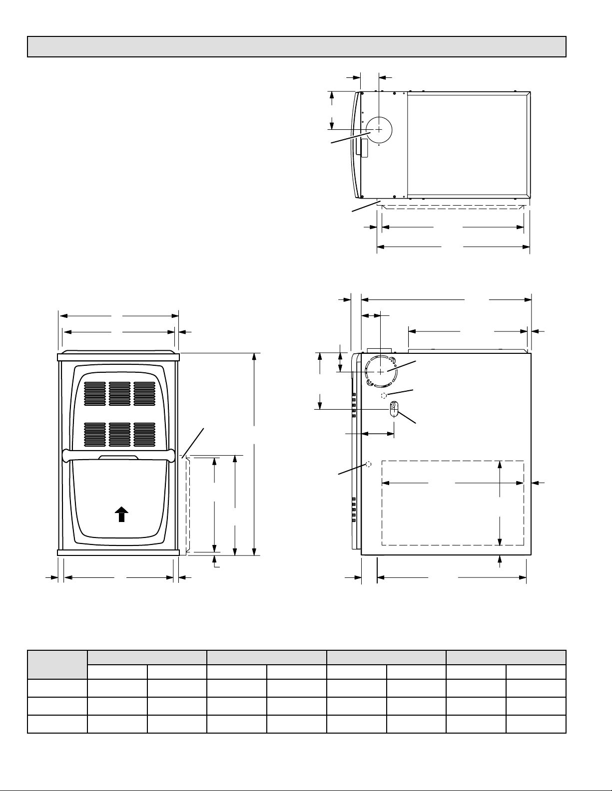
Unit Dimensions
3-1/8 (79)
D
FLUE OUTLET
(Top)
3
OPTIONAL
EXTERNAL
SIDE RETURN
AIR FILTER KIT
(Either Side)
SUPPLY AIR
OPENING
23-3/4
(603)
25
(635)
TOP VIEW
3/4 (19)
Front Panel
A
B
9/16 (14)
3
OPTIONAL
EXTERNAL
SIDE RETURN
AIR FILTER KIT
(Either Side)
33
(838)
3 (76) Right
6-3/4 (171) Left
9-1/8 (232) Right
8-5/8 (219) Left
5-3/8 (137) Right
1-9/16 (40) Left
3-1/4 (83)
2
FLUE OUTLET
(Either Side)
ELECTRICAL INLET
(Either Side)
GAS PIPING INLET
(Either Side)
27-3/4
(705)
19-7/16
(494)
9/16
(14)
ELECTRICAL INLET
3/4
(19)
AIR FLOW
C
1
Bottom Return
Air Opening
3/4
(19)
14-3/4
(375)
(406)
5/8
(16)
16
(Either Side)
3-1/4
(83)
23
(584)
1
Side Return
Air Opening
(Either Side)
23-1/2
(597)
1
Bottom Return
Air Opening
14
(356)
1-15/16 (49)
FRONT VIEW SIDE VIEW
Capacity
in. mm in. mm in. mm in. mm
070-12 14-1/2 368 13-3/8 340 13 330 4-3/4 121
090-16 17-1/2 446 16-3/8 416 16 406 6-1/4 159
110-20 21 533 19-7/8 504 19-1/2 495 8 203
A B C D
1-1/2
(38)
507335-02Page 2 of 39 Issue 2128
Page 3
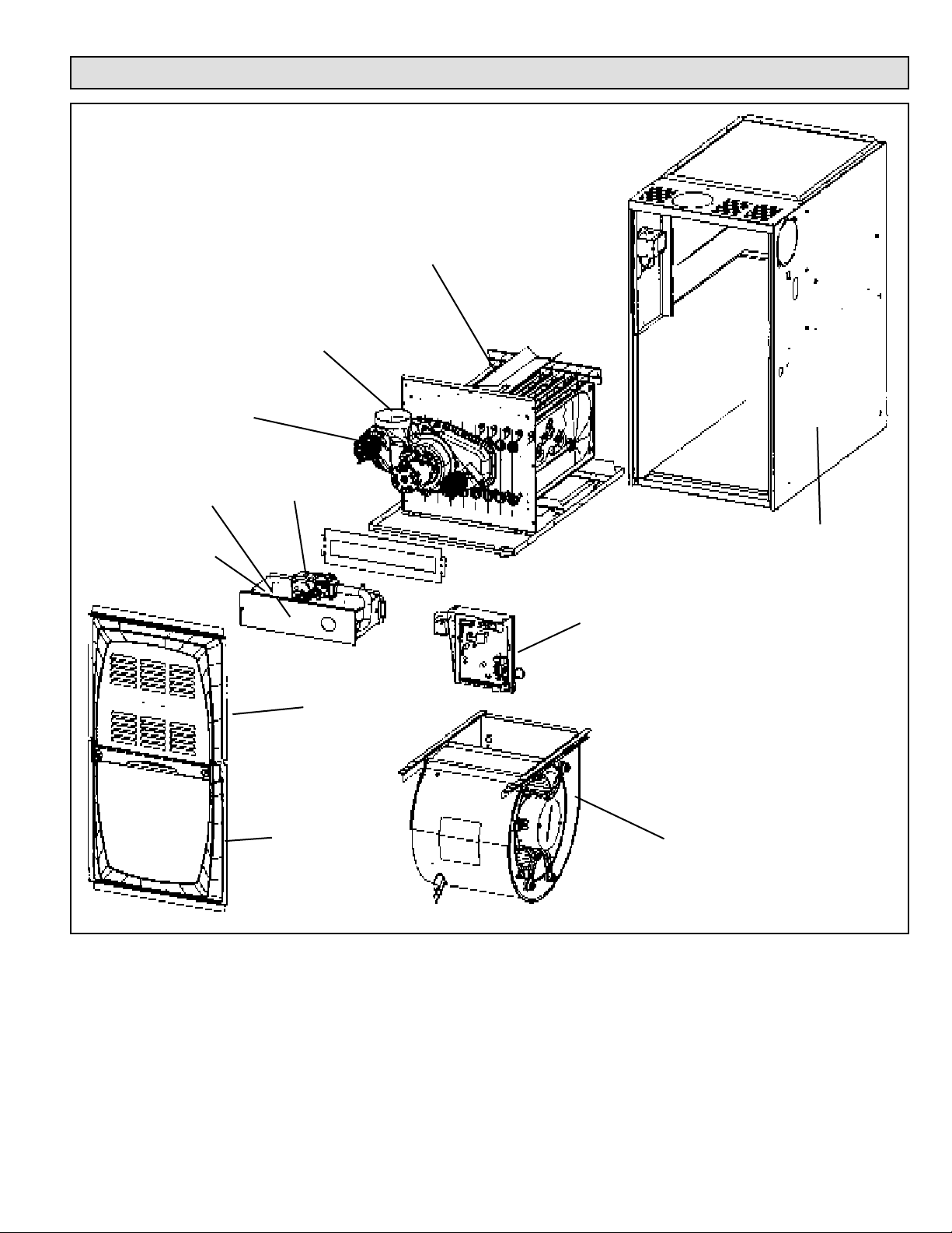
Parts Arrangement
COMBUSTION AIR
COMBUSTION AIR
INDUCER PRESSURE
SWITCH
ROLLOUT
LOCATED INSIDE
BURNER BOX
HEAT
EXCHANGER
INDUCER
GAS
VALVE
BURNER
BOX
BURNER
ACCESS
PANEL
BLOWER
ACCESS
PANEL
CABINET
CONTROL
BOX
(INCLUDES INTEGRATED
CONTROL, AND TRANSFORMER)
BLOWER
ASSEMBLY
Figure 1.
507335-02 Page 3 of 39Issue 2128
Page 4
80G2UH-V Gas Furnace
The 80G2UH-V gas furnace is shipped ready for
installation in the upow or horizontal position (left or right).
The furnace is shipped with the bottom panel in place. The
bottom panel must be removed if the unit is to be installed
in a horizontal application. The panel may also be removed
in upow applications.
The furnace is equipped for installation in natural gas
applications. A conversion kit (ordered separately) is
required for use in propane/LP gas applications.
Shipping and Packing List
Clearances
Adequate clearance must be made around the air openings
into the vestibule area. In order to ensure proper unit
operation, combustion and ventilation air supply must be
provided according to the current National Fuel Gas Code.
Vent installations must be consistent with the venting
tables (in this instruction) and applicable provisions of local
building codes.
This furnace is CSA International certied for installation
clearances to combustible material as listed on the
unit nameplate and in the tables in Figure 8 and Figure
11. Installers should also consider the greater of either
accessibility/service clearances or re protection
clearances.
1 - Assembled Gas Furnace
1 - Bag assembly containing the following:
2 - Screws
3 - Wire nuts
1 - Snap bushing
1 - Snap Plug
1 - Wire tie
1 - Vent warning label
1 - Owner’s manual and warranty card
Check equipment for shipping damage. If you nd any
damage, immediately contact the last carrier.
Please refer to specication sheets for available
accessories.
Safety Information
DANGER
NOTE: For installation on combustible oors, the furnace
shall not be installed directly on carpeting, tile, or other
combustible material other than wood ooring.
Installed Locations
For installation in a residential garage, the furnace must be
installed so that the burner(s) and the ignition source are
located no less than 18 inches (457 mm) above the oor.
The furnace must be located or protected to avoid physical
damage by vehicles. When a furnace is installed in a public
garage, hangar, or other building that has a hazardous
atmosphere, the furnace must be installed according to
recommended good practice requirements and current
National Fuel Gas Code.
Temperature Rise
NOTE: Furnace must be adjusted to obtain a temperature
rise (high and low re) within the range(s) specied on the
unit nameplate. Failure to do so may cause erratic limit
operation and may result in premature heat exchanger
failure.
This furnace must be installed so that its electrical
components are protected from water.
DANGER OF EXPLOSION!
There are circumstances in which odorant used with
LP/Propane gas can lose its scent. In case of a leak,
LP/Propane gas will settle close to the oor and may be
difcult to smell. An LP/Propane leak detector should be
installed in all LP applications.
Certications
These units are CSA International certied to ANSI Z21.47.
In the USA, installation of gas furnaces must conform with
local building codes. In the absence of local codes, units
must be installed according to the current National Fuel
Gas Code (ANSI-Z223.1). The National Fuel Gas Code is
available from the following address: American National
Standards Institute, Inc., 11 West 42nd Street, New York,
NY 10036.
Installed in Combination with a Cooling Coil
When this furnace is used with cooling units, it shall be
installed in parallel with, or on the upstream side of, cooling
units to avoid condensation in the heating compartment.
See Figure 2. With a parallel ow arrangement, a damper
(or other means to control the ow of air) must adequately
prevent chilled air from entering the furnace. If the damper
is manually operated, it must be equipped to prevent
operation of either the heating or the cooling unit, unless it
is in the full HEAT or COOL setting. See Figure 2.
507335-02Page 4 of 39 Issue 2128
Page 5
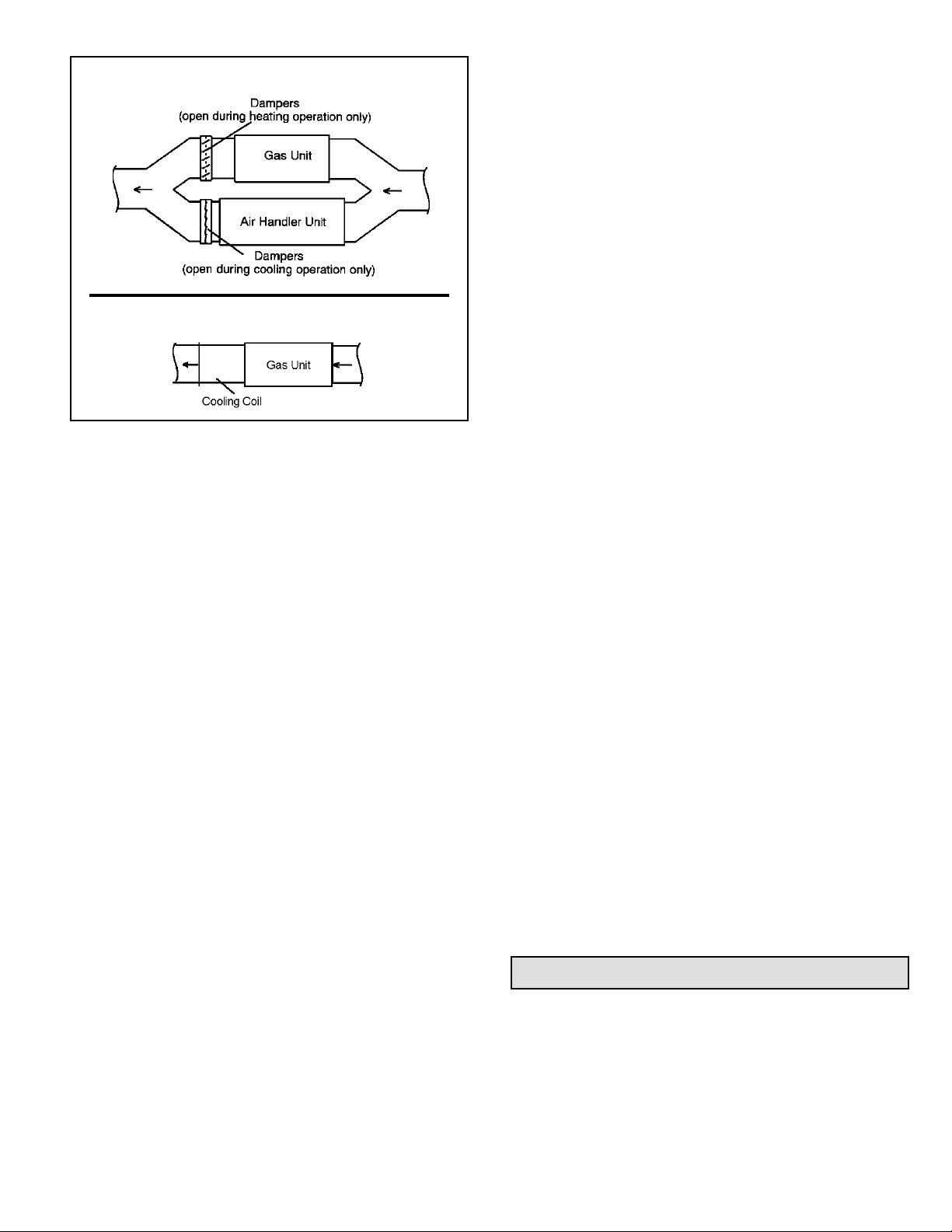
Heating Unit Installed Parallel to Air Handler Unit
Heating Unit Installed Upstream of Cooling Unit
Figure 2.
When installed, this furnace must be electrically grounded
according to local codes. In addition, in the United States,
installation must conform with the current National
Electric Code, ANSI/NFPA No. 70. The National Electric
Code (ANSI/NFPA No. 70) is available from the following
address:
National Fire Protection Association
1 Battery March Park
Quincy, MA 02269
NOTE: This furnace is designed for a minimum continuous
return air temperature of 60° F (16°C) or an intermittent
operation down to 55° F (13°C) dry bulb for cases where
a night setback thermostat is used. Return air temperature
must not exceed 85° F (29°C) dry bulb.
This furnace may be installed in alcoves, closets, attics,
basements, garages, and utility rooms in the upow or
horizontal position.
This furnace design has not been certied for installation in
mobile homes, recreational vehicles, or outdoors.
Use of Furnace as a Construction Heater
Units may be used for heating of buildings or structures
under construction, if the following conditions are met to
ensure proper operation.
DO NOT USE THE UNIT FOR CONSTRUCTION HEAT
UNLESS ALL OF THE FOLLOWING CRITERIA ARE
MET:
a. Furnace must be in its nal location. The vent system
must be permanently installed per these installation
instructions.
b. Furnace must be installed as a two pipe system
and one hundred percent (100%) outdoor air must
be provided for combustion air requirements during
construction.
c. A room thermostat must control the furnace. The use
of xed jumpers that will provide continuous heating is
prohibited.
d. The input rate and temperature rise must be set per
the furnace rating plate.
e. Supply and Return air ducts must be provided and
sealed to the furnace. Return air must be terminated
outside of the space where furnace is installed.
f. Return air temperature range between 60°F (16°C)
and 80°F (27°C) must be maintained.
g. MERV 11 or greater air lters must be installed in
the system and must be regularly inspected and
maintained (e.g., regular static checks and replaced at
end of life) during construction.
h. Blower and vestibule access panels must be in place
on the furnace at all times.
i. The furnace heat exchanger, components, duct
system, and evaporator coils must be thoroughly
cleaned following nal construction clean−up.
j. Air lters must be replaced upon construction
completion.
k. All furnace operating conditions (including ignition,
input rate, temperature rise and venting) must
be veried in accordance with these installation
instructions.
EQUIPMENT MAY EXPERIENCE PREMATURE
COMPONENT FAILURE AS A RESULT OF FAILURE TO
FOLLOW THE ABOVE INSTALLATION INSTRUCTIONS.
FAILURE TO FOLLOW THE ABOVE INSTALLATION
INSTRUCTIONS VOIDS THE MANUFACTURER’S
EQUIPMENT LIMITED WARRANTY. ALLIED AIR
DISCLAIMS ALL LIABILITY IN CONNECTION WITH
INSTALLER’S FAILURE TO FOLLOW THE ABOVE
INSTALLATION INSTRUCTIONS.
NOTWITHSTANDING THE FOREGOING, INSTALLER
IS RESPONSIBLE FOR CONFIRMING THAT THE USE
OF CONSTRUCTION HEAT IS CONSISTENT WITH
THE POLICIES AND CODES OF ALL REGULATING
ENTITIES. ALL SUCH POLICIES AND CODES MUST BE
ADHERED TO.
General
These instructions are intended as a general guide and do
not supersede local codes in any way. Consult authorities
having jurisdiction before installation.
In addition to the requirements outlined previously, the
following general recommendations must be considered
when installing one of these furnaces:
507335-02 Page 5 of 39Issue 2128
Page 6
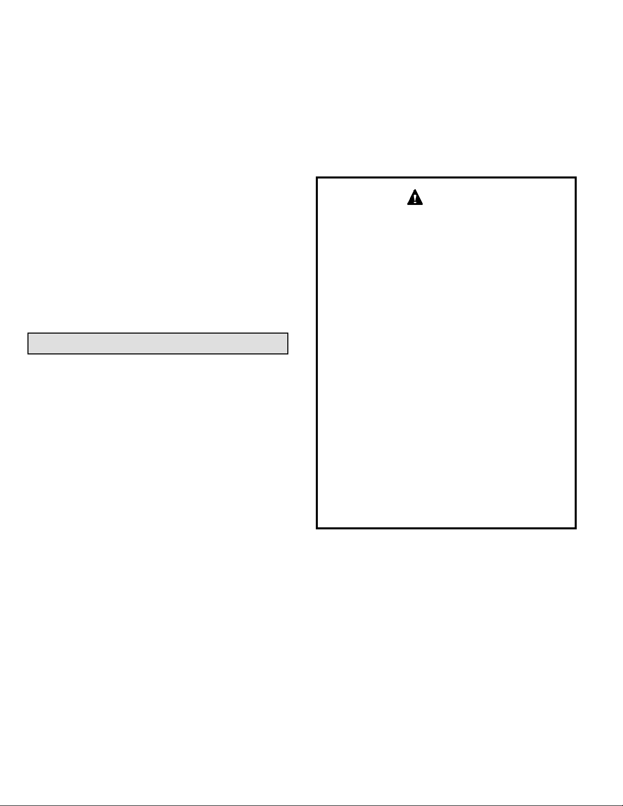
• Place the furnace as close to the center of the air
distribution system as possible. The furnace should
also be located close to the chimney or vent termination
point.
• Do not install the furnace where drafts might blow
directly into it. This could cause improper combustion.
• Do not block the furnace combustion air openings with
clothing, boxes, doors, etc. Air is needed for proper
combustion and safe unit operation.
• When the furnace is installed in an attic or other
insulated space, keep insulation away from the
furnace.
NOTE: The Commonwealth of Massachusetts stipulates
these additional requirements:
• Gas furnaces shall be installed by a licensed plumber
or tter only.
• The gas cock must be “T handle” type.
• When a furnace is installed in an attic, the passageway
to and service area surrounding the equipment shall
be oored.
Combustion, Dilution & Ventilation Air
In the past, there was no problem in bringing in sufcient
outdoor air for combustion. Inltration provided all the air
that was needed. In today’s homes, tight construction
practices make it necessary to bring in air from outside
for combustion. Take into account that exhaust fans,
appliance vents, chimneys, and replaces force additional
air that could be used for combustion out of the house.
Unless outside air is brought into the house for combustion,
negative pressure (outside pressure is greater than inside
pressure) will build to the point that a downdraft can occur
in the furnace vent pipe or chimney. As a result, combustion
gases enter the living space creating a potentially
dangerous situation.
replaces, exhaust fans, or clothes dryers are used at the
same time as the furnace, much more air is necessary to
ensure proper combustion and to prevent a downdraft.
Insufcient air causes incomplete combustion which can
result in carbon monoxide.
In addition to providing combustion air, fresh outdoor air
dilutes contaminants in the indoor air. These contaminants
may include bleaches, adhesives, detergents, solvents
and other contaminants which can corrode furnace
components.
WARNING
Insufcient combustion air can cause headaches,
nausea, dizziness or asphyxiation. It will also cause
excess water in the heat exchanger resulting in rusting
and premature heat exchanger failure. Excessive
exposure to contaminated combustion air will result
in safety and performance related problems. Avoid
exposure to the following substances in the combustion
air supply:
• Permanent wave solutions
• Chlorinated waxes and cleaners
• Chlorine base swimming pool chemicals
• Water softening chemicals
• De-icing salts or chemicals
• Carbon tetrachloride
• Halogen type refrigerants
• Cleaning solvents (such as perchloroethylene)
• Printing inks, paint removers, varnishes, etc.
• Hydrochloric acid
• Cements and glues
• Antistatic fabric softeners for clothes dryers
• Masonry acid washing materials
In the absence of local codes concerning air for combustion
and ventilation, use the guidelines and procedures in this
section to install these furnaces to ensure efcient and
safe operation. You must consider combustion air needs
and requirements for exhaust vents and gas piping.
A portion of this information has been reprinted
with permission from the National Fuel Gas Code
(ANSI-Z223.1). This reprinted material is not the complete
and ofcial position of the ANSI on the referenced subject,
which is represented only by the standard in its entirety.
All gas red appliances require air for the combustion
process. If sufcient combustion air is not available, the
furnace or other appliances will operate inefciently
and unsafely. Enough air must be provided to meet the
needs of all fuel burning appliances and appliances such
as exhaust fans which force air out of the house. When
The requirements for providing air for combustion and
ventilation depend largely on whether the furnace is
installed in an unconned or a conned space.
Unconned Space
An unconned space is an area such as a basement
or large equipment room with a volume greater than 50
cubic feet (1.42 m3) per 1,000 Btu (.29 kW) per hour of
the combined input rating of all appliances installed in that
space. This space also includes adjacent rooms which are
not separated by a door. Though an area may appear to
be unconned, it might be necessary to bring in outdoor air
for combustion if the structure does not provide enough air
by inltration. If the furnace is located in a building of tight
construction with weather stripping and caulking around
the windows and doors, follow the procedures in the air
from outside section.
507335-02Page 6 of 39 Issue 2128
Page 7
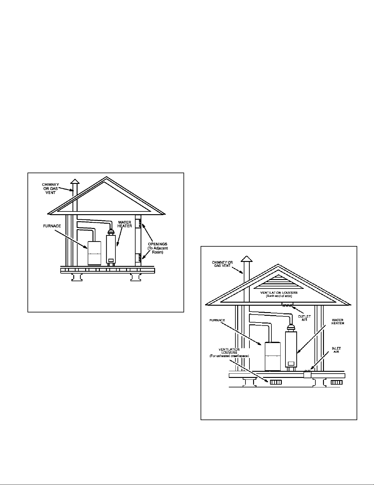
Conned Space
A conned space is an area with a volume less than 50
cubic feet (1.42 m3) per 1,000 Btu (.29 kW) per hour of
the combined input rating of all appliances installed in that
space. This denition includes furnace closets or small
equipment rooms.
When the furnace is installed so that supply ducts carry
air circulated by the furnace to areas outside the space
containing the furnace, the return air must be handled by
ducts which are sealed to the furnace casing and which
terminate outside the space containing the furnace. This
is especially important when the furnace is mounted on
a platform in a conned space such as a closet or small
equipment room. Even a small leak around the base of the
unit at the platform or at the return air duct connection can
cause a potentially dangerous negative pressure condition.
Air for combustion and ventilation can be brought into the
conned space either from inside the building or from
outside.
Air from Outside
If air from outside is brought in for combustion and
ventilation, the conned space must have two permanent
openings. One opening shall be within 12 inches (305
mm) of the top of the enclosure and one opening within
12 inches (305 mm) of the bottom. These openings must
communicate directly or by ducts with the outdoors or
spaces (crawl or attic) that freely communicate with the
outdoors or indirectly through vertical ducts. Each opening
shall have a minimum free area of 1 square inch (645 mm2)
per 4,000 Btu (1.17 kW) per hour of total input rating of all
equipment in the enclosure. See Figure 4 and Figure 5.
When communicating with the outdoors through horizontal
ducts, each opening shall have a minimum free area of 1
square inch (645 mm2) per 2,000 Btu (.56 kW) per total
input rating of all equipment in the enclosure. See Figure 6.
When ducts are used, they shall be of the same cross
sectional area as the free area of the openings to which
they connect. The minimum dimension of rectangular
air ducts shall be no less than 3 inches (75 mm). In
calculating free area, the blocking effect of louvers, grilles,
or screens must be considered. If the design and free area
of protective covering is not known for calculating the size
opening required, it may be assumed that wood louvers
will have 20 to 25 percent free area and metal louvers and
grilles will have 60 to 75 percent free area. Louvers and
grilles must be xed in the open position or interlocked
with the equipment so that they are opened automatically
during equipment operation.
NOTE: Each opening shall have a free area of at least one square
inch per 1,000 Btu (645 mm² per .29 kW) per hour of the total
input rating of all equipment in the enclosure, but not less than 100
square inches (64516 mm²).
Figure 3. Equipment in Conned Space - All Air From
Inside
Air from Inside
If the conned space that houses the furnace adjoins a
space categorized as unconned, air can be brought in
by providing two permanent openings between the two
spaces. Each opening must have a minimum free area of 1
square inch (645 mm2) per 1,000 Btu (.29 kW) per hour of
total input rating of all gas red equipment in the conned
space. Each opening must be at least 100 square inches
(64516 mm2). One opening shall be within 12 inches (305
mm) of the top of the enclosure and one opening within 12
inches (305 mm) of the bottom. See Figure 3.
507335-02 Page 7 of 39Issue 2128
NOTE: The inlet and outlet air openings shall each have a free
area of at least one square inch per 4,000 Btu (645 mm² per
1.17 kW) per hour of the total input rating of all equipment in the
enclosure.
Figure 4. Equipment in Conned Space - All Air from
Outside
(Inlet Air from Crawlspace & Outlet Air to Ventilated
Attic)
Page 8
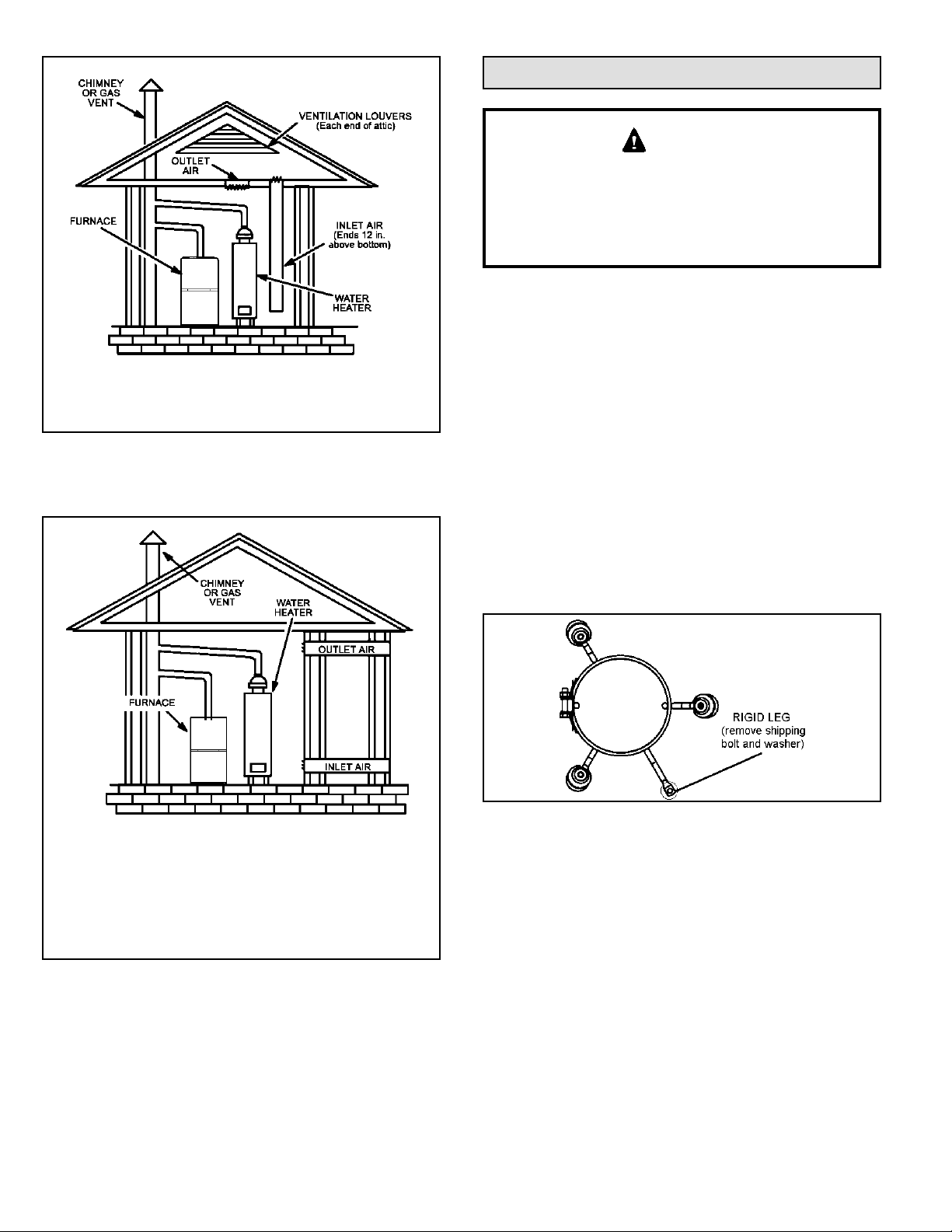
NOTE: The inlet and outlet air openings shall each have a free
area of at least one square inch per 4,000 Btu (645 mm² per
1.17 kW) per hour of the total input rating of all equipment in the
enclosure.
Setting Equipment
WARNING
Do not install the furnace on its front or its back. Do not
connect the return air ducts to the back of the furnace.
Doing so will adversely affect the operation of the safety
control devices, which could result in personal injury or
death.
The gas furnace can be installed as shipped in either the
upow position or the horizontal position.
Select a location that allows for the required clearances
that are listed on the unit nameplate. Also consider gas
supply connections, electrical supply, vent connection, and
installation and service clearances [24 inches (610 mm) at
unit front]. The unit must be level.
Figure 5. Equipment in Conned Space - All Air from
Outside
(All Air through Ventilated Attic)
NOTE: Each air duct opening shall have a free area of at least one
square inch per 2,000 Btu (645 mm² per .59 kW) per hour of the
total input rating of all equipment in the enclosure. If the equipment
room is located against an outside wall and the air openings
communicate directly with the outdoors, each opening shall have
a free area of at least 1 square inch per 4,000 Btu (645 mm² per
1.17 kW) per hour of the total input rating of all other equipment in
the enclosure.
NOTE: Units with 1/2 hp blower motors are equipped with
three exible legs and one rigid leg. See Figure 7. The rigid
leg is equipped with a shipping bolt and a at white plastic
washer (rather than the rubber mounting grommet used
with a exible mounting leg). The bolt and washer must be
removed before the furnace is placed into operation. After
the bolt and washer have been removed, the rigid leg will
not touch the blower housing.
Units with 1/2 HP
Blower Motor.
Figure 7.
Upow Applications
Allow for clearances to combustible materials as indicated
on the unit nameplate. Minimum clearances for closet or
alcove installations are shown in Figure 8.
Figure 6. Equipment in Conned Space - All Air from
Outside
507335-02Page 8 of 39 Issue 2128
Page 9
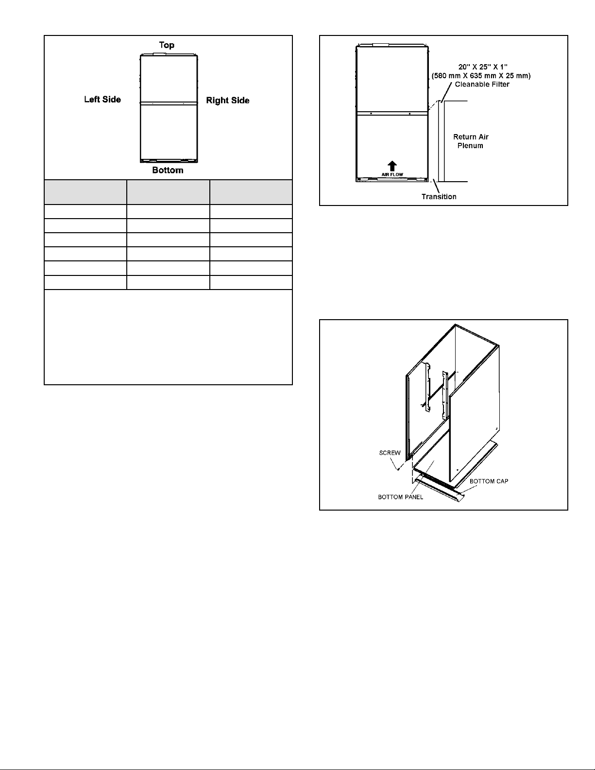
Type of Vent
Connector
Top 1 in. (25 mm) 1 in. (25 mm)
* Front 2-1/4 in. (57 mm) 2-1/4 in. (57 mm)
Back 0 0
Sides 0† 0
Vent 6 in. (152 mm) 1 in. (25 mm)
Floor 0‡ 0‡
* Front clearance In alcove Installation must be 24 in. (610
mm). Maintain a minimum of 24 in. (610 mm) for front service
access.
‡ For installation on a combustible oor, do not install the
furnace directly on carpeting, tile or other combustible
materials other than wood ooring.
† Left side requires 3 inches if a single wall vent is used on
14-1/2 inch cabinets.
Type C Type B1
Figure 8. Upow Application Installation Clearances
Return Air - Upow Applications
Return air can be brought in through the bottom or either
side of the furnace installed in an upow application. If the
furnace is installed on a platform with bottom return, make
an airtight seal between the bottom of the furnace and the
platform to ensure that the furnace operates properly and
safely. The furnace is equipped with a removable bottom
panel to facilitate installation.
Markings are provided on both sides of the furnace cabinet
for installations that require side return air. Cut the furnace
cabinet at the maximum dimensions shown on Page 2.
Figure 9. Single Side Return Air
(with transition and lter)
Removing the Bottom Panel
Remove the two screws that secure the bottom cap to the
furnace. Pivot the bottom cap down to release the bottom
panel. Once the bottom panel has been removed, reinstall
the bottom cap. See Figure 10.
Figure 10. Removing the Bottom Panel
NOTE: 20C and 20D units that require air volumes over
1800 cfm (850 L/s) must have one of the following:
1. Single side return air with transition to accommodate
20 x 25 x 1 in. (508 x 635 x 25 mm) cleanable air lter.
(Required to maintain proper air velocity.) See Figure
9.
2. Single side return air with optional return airbase. See
Figure 12.
3. Bottom return air.
4. Return air from both sides.
5. Bottom and one side return air.
507335-02 Page 9 of 39Issue 2128
Page 10
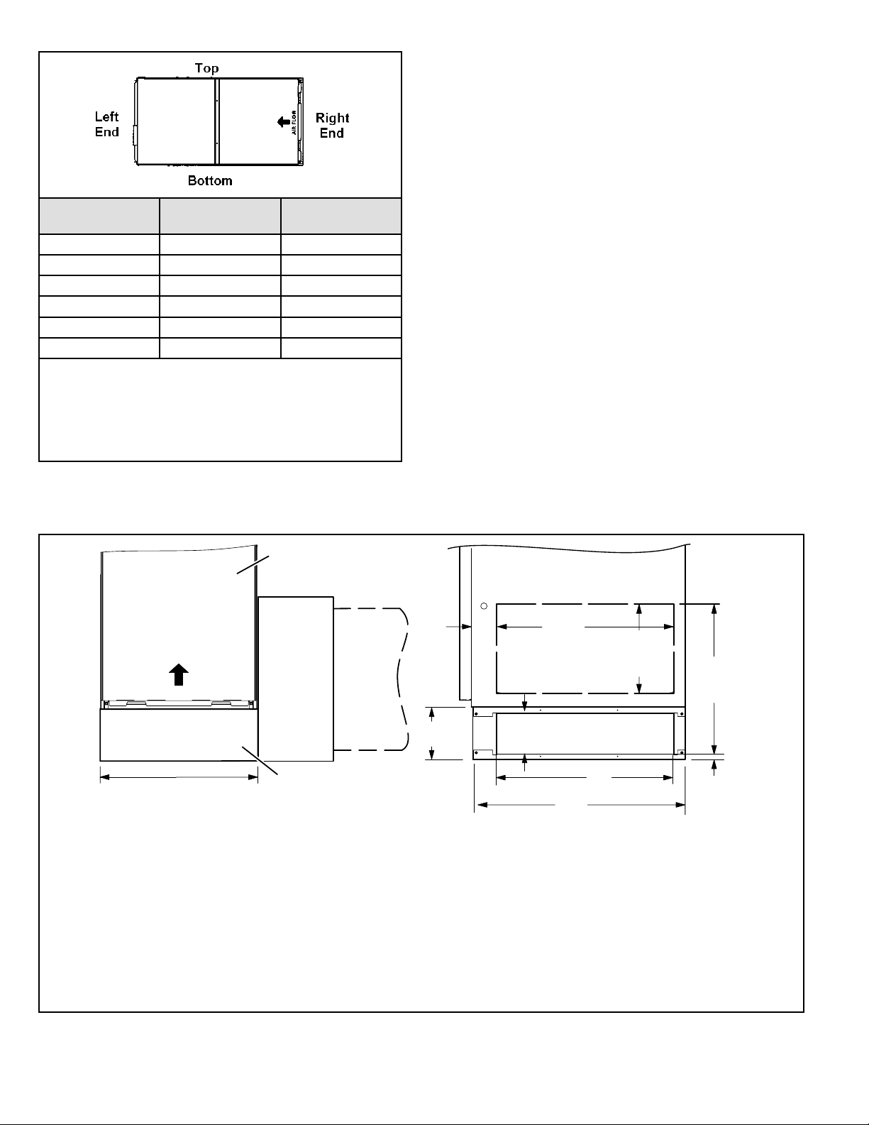
Horizontal Applications
The furnace can be installed in horizontal applications.
Order horizontal suspension kit (51W10) or use equivalent
suspension method.
Allow for clearances to combustible materials as indicated
on the unit nameplate. Minimum clearances for closet or
alcove installations are shown in Figure 11.
Type of Vent
Connector
Type C Type B1
Top 0 0
* Front 2-1/4 in. (57 mm) 2-1/4 in. (57 mm)
Back 0 0
Sides 2 in. (51 mm) 2 in. (51 mm)
Vent 6 in. (152 mm) 1 in. (25 mm)
Floor 0‡ 0‡
* Front clearance in alcove installation must be 24 in. (610
mm). Maintain a minimum of 21 in. (610 mm) for front service
access.
‡ For installations on a combustible oor, do not install
the furnace directly on carpeting, tile or other combustible
materials other than wood ooring.
Figure 11. Horizontal Application Installation
Clearances
FURNACE
FRONT
IF BASE
IS USED
WITHOUT
INDOOR AIR
QUALITY
CABINET
AIR FLOW
IAQ CABINET,
A SINGLE
RETURN AIR
PLENUM
MUST
COVER BOTH
UNIT AND
RETURN
AIR BASE
OPENINGS
This furnace may be installed in either an attic or a crawl
space. Either suspend the furnace from roof rafters or oor
joists, as shown in Figure 13, or install the furnace on a
platform, as shown in Figure 14.
NOTE: Heavy gauge perforated sheet metal straps may
be used to suspend the unit from roof rafters or ceiling
joists. When straps are used to suspend the unit in this
way, support must be provided for both the ends. The
straps must not interfere with the plenum or exhaust
piping installation. Cooling coils and supply and return air
plenums must be supported separately.
NOTE: When the furnace is installed on a platform in a
crawlspace, it must be elevated enough to avoid water
damage and to allow the evaporator coil to drain.
1
3−1/4
(83)
7−1/4
(184)
23 (584)
Overall
(Maximum)
1
Unit side return air
Opening
5−5/8
(143)
SIDE RETURN
AIR OPENINGS
(Either Side)
1
Minimum
11 (279)
2
Maximum
14 (356)
1
22−7/16
(570)
Overall
(Maximum)
26−7/8
(683)
23
(584)
14-1/2 (368) A Width (68W61)
17-1/2 (446) B Width (68W62)
21 (533) C Width (68W63)
24-1/2 (622) D Width (68W64)
FRONT VIEW
NOTE: Optional Side Return Air Filter Kits are not for use with Return Air Base.
1 Both the unit return air opening and the base return air opening must be covered by a single plenum or IAQ cabinet.
Minimum unit side return air opening dimensions for units requiring 1800 cfm or more of air (W x H): 23 x 11 in. (584 x 279 mm).
The opening can be cut as needed to accommodate plenum or IAQ cabinet while maintaining dimensions shown.
Side return air openings must be cut in the eld. There are cutting guides stenciled on the cabinet for the side return air opening.
The size of the opening must not extend beyond the markings on the furnace cabinet.
² To minimize pressure drop, the largest opening height possible (up to 14 inches) is preferred.
OPTIONAL
RETURN
AIR BASE
SIDE VIEW
Figure 12. Optional Return Air Base
(Upow Applications Only - For use with A, B, C and D cabinets)
3/4
(19)
507335-02Page 10 of 39 Issue 2128
Page 11
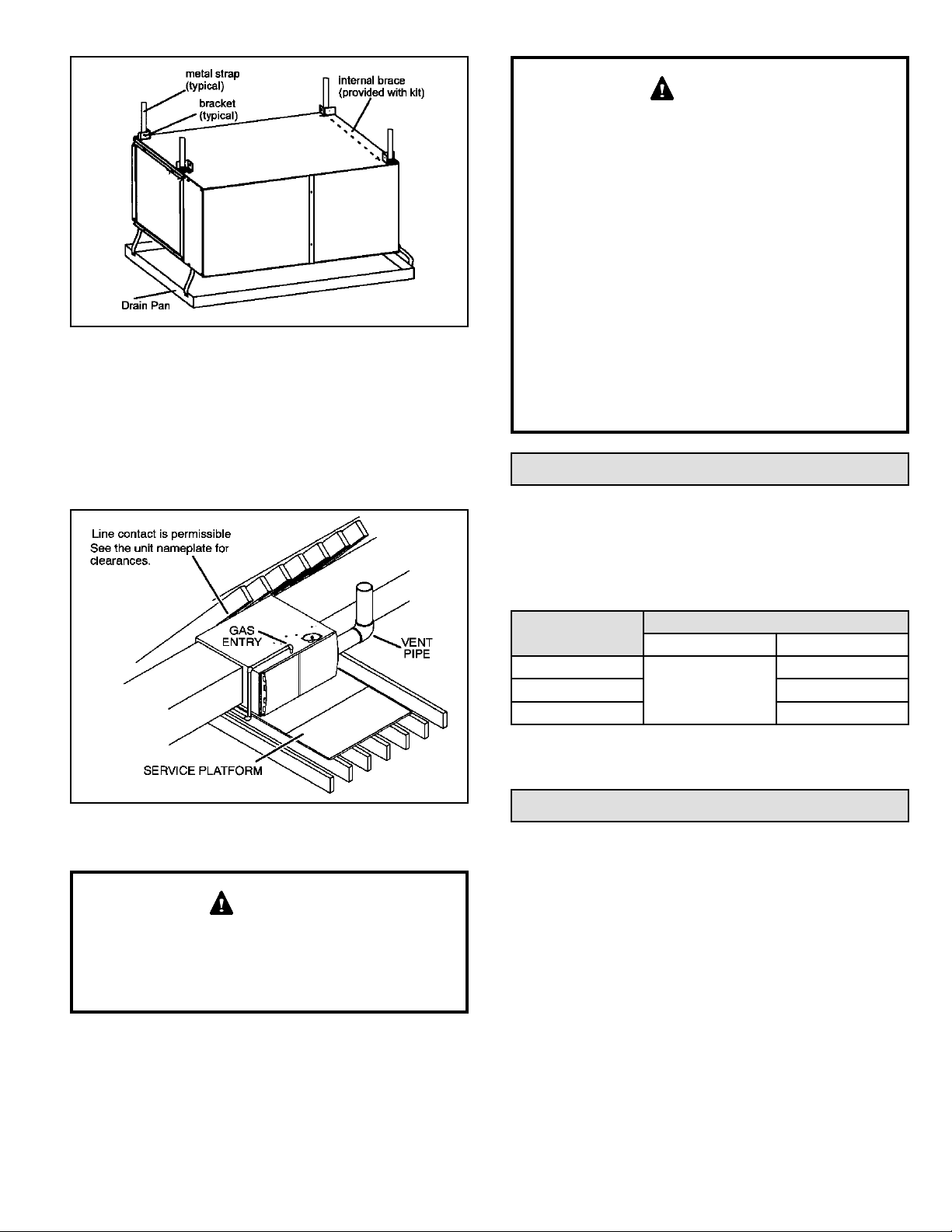
Figure 13. Horizontal Application
Unit Suspended in Attic or Crawlspace
Return Air - Horizontal Applications
Return air must be brought in through the end of a furnace
installed in a horizontal application. The furnace is equipped
with a removable bottom panel to facilitate installation. See
Figure 10.
WARNING
Improper installation of the furnace can result in
personal injury or death. Combustion and ue products
must never be allowed to enter the return air system or
the living space. Use screws and joint tape to seal the
return air system to the furnace.
In platform installations with bottom return air, the furnace
should be sealed airtight to the return air plenum. A door
must never be used as a portion of the return air duct
system. The base must provide a stable support and an
airtight seal to the furnace. Allow absolutely no sagging,
cracks, gaps, etc..
The return and supply air duct systems must never
be connected to or from other heating devices such
as a replace or stove, etc.. Fire, explosion, carbon
monoxide poisoning, personal injury and/or property
damage could result.
Filters
This unit is not equipped with a lter or rack. A eld provided
high velocity lter is required for the unit to operate properly.
Table 1 lists recommended lter sizes.
Figure 14. Horizontal Application
Unit Installed on Platform
WARNING
The inner blower panel must be securely in place when
the blower and burners are operating. Gas fumes,
which could contain carbon monoxide, can be drawn
into living space resulting in personal injury or death.
A lter must be in place any time the unit is operating.
Furnace Cabinet
Width
14-1/2”
17-1/2” 16 x 25 x 1 (1)
21” 20 x 25 x 1 (1)
Side Return Bottom Return
16 x 25 x 1 (1)
Filter Size
14 x 25 x 1 (1)
Table 1.
Duct System
Use industry approved standards (such as those published
by Air Conditioning Contractors of America or American
Society of Heating, Refrigerating and Air Conditioning
Engineers) to size and install the supply and return air duct
system. This will result in a quiet and low static system that
has uniform air distribution.
NOTE: Do not operate the furnace in the heating mode
with an external static pressure that exceeds 0.8 inches
w.c. Higher external static pressures may cause erratic
limit operation.
507335-02 Page 11 of 39Issue 2128
Page 12
Supply Air Plenum
If the furnace is installed without a cooling coil, a removable
access panel must be installed in the supply air duct. The
access panel should be large enough to permit inspection
(either by smoke or reected light) of the heat exchanger
for leaks after the furnace is installed. The furnace access
panel must always be in place when the furnace is operating
and it must not allow leaks into the supply air duct system.
Return Air Plenum
NOTE: Return air must not be drawn from a room where
this furnace, or any other gas fueled appliance (i.e., water
heater), or carbon monoxide producing device (i.e., wood
replace) is installed.
When return air is drawn from a room, a negative pressure
is created in the room. If a gas appliance is operating in
a room with negative pressure, the ue products can be
pulled back down the vent pipe and into the room. This
reverse ow of the ue gas may result in incomplete
combustion and the formation of carbon monoxide gas.
This toxic gas might then be distributed throughout the
house by the furnace duct system.
In upow applications, the return air can be brought
in through the bottom or either side of the furnace. If a
furnace with bottom return air is installed on a platform,
make an airtight seal between the bottom of the furnace
and the platform to ensure that the unit operates properly
and safely. Use berglass sealing strips, caulking, or
equivalent sealing method between the plenum and the
furnace cabinet to ensure a tight seal. If a lter is installed,
size the return air duct to t the lter frame.
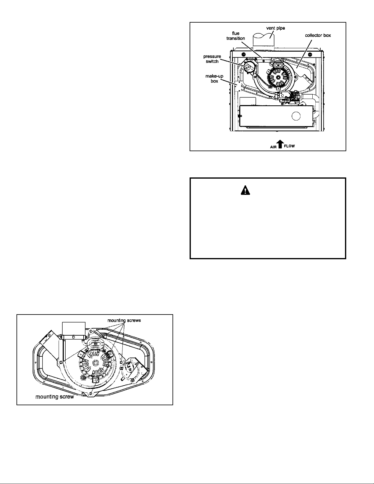
Figure 16. Upow Position
Top Vent Discharge
IMPORTANT
The unit will not vent properly with the ue transition
pointed down in the 6 o’clock position.
The combustion air inducer may be rotated clockwise
or counterclockwise by 90° to allow for top or side vent
discharge in all applications. When the unit is installed,
the ue transition must be in the 9 o’clock, 12 o’clock or
3 o’clock position.
Venting
A 4 inch diameter ue transition is factory installed on
the combustion air inducer outlet of all models. Figure 16
shows the combustion air inducer as shipped from the
factory.
Figure 15. Mounting Screws Location
If necessary reposition the combustion air inducer,
pressure switch and/or make-up box as needed per the
following steps. See Figure 16 through Figure 22.
1. Remove the four mounting screws (Figure 15) which
secure the combustion air inducer / pressure switch
assembly to the orice plate. Lift the assembly and
rotate it 90° clockwise or counter clockwise to either
the 3 o’clock position or 9 o’clock position. Resecure
with four screws. Gasket should be left in place.
2. Use tin snips to cut preferred opening on the cabinet
for repositioning the ue outlet. Use the cut-out piece
as a cover plate to patch unused opening on cabinet.
507335-02Page 12 of 39 Issue 2128
Page 13
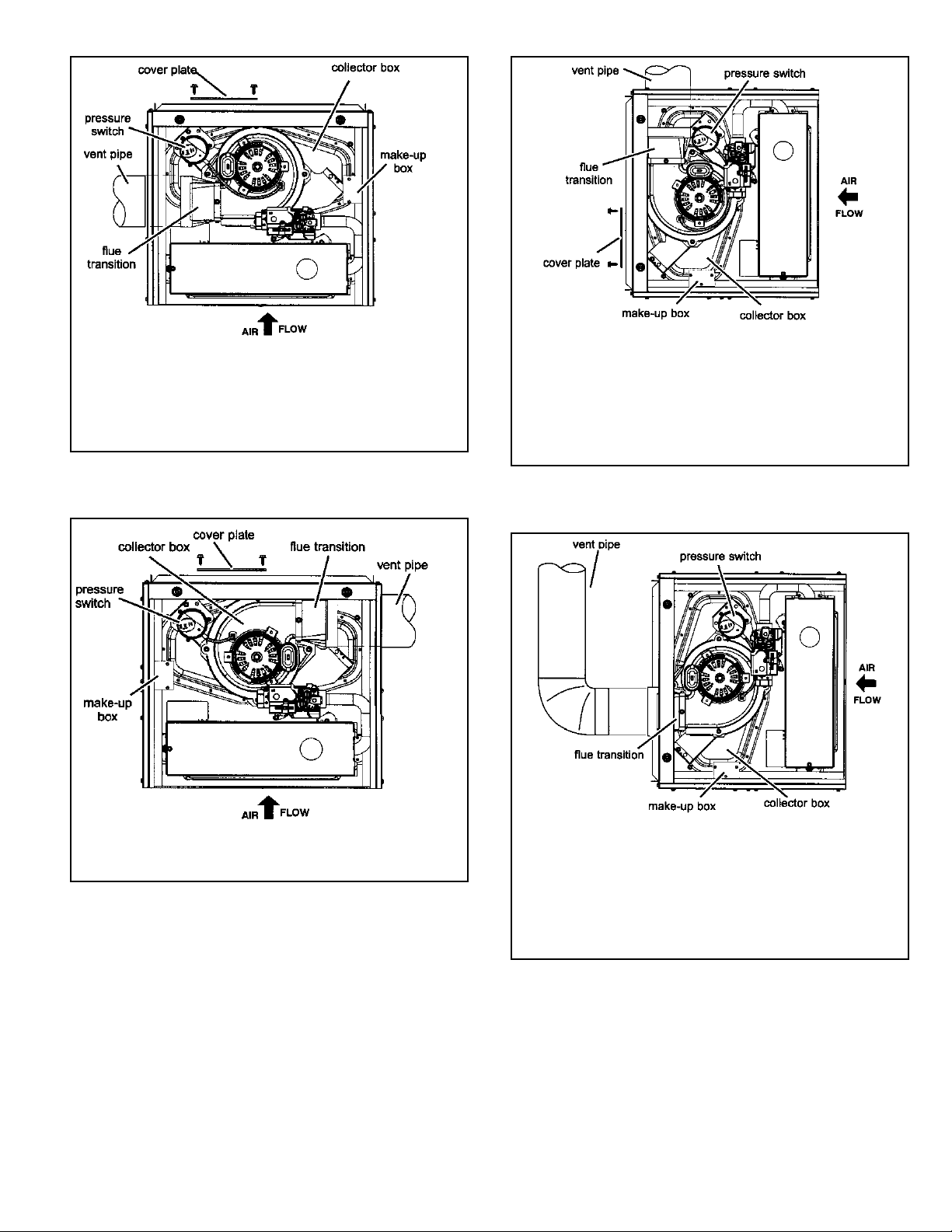
• Remove make-up box assembly (2 screws) and cut wire tie to
free make-up box wires. Reinstall make-up box on other side of
cabinet.
• Resecure make-up box wires: Either pull excess wires through
the blower compartment and secure using supplied wire tie, or
coil excess wire and secure to the gas manifold.
Figure 17. Upow Position
Left Side Vent Discharge
• Disconnect pressure switch hose from barbed tting on the
pressure switch assembly. Remove pressure switch assembly
(1 screw) and cut wire tie to free pressure switch wires. Reinstall
pressure switch on the other side of orice plate and reconnect
pressure switch hose.
• Resecure pressure switch wires: Either pull excess wires
through the blower compartment and secure using supplied
wire tie, or coil excess wire and secure to the gas manifold.
Figure 19. Horizontal Left Position
Top Vent Discharge
• Pressure switch tubing may be too long. Cut to t, then reattach
to barbed tting on pressure switch. Tubing must not be allowed
to sag.
Figure 18. Upow Position
Right Side Vent Discharge
507335-02 Page 13 of 39Issue 2128
• Disconnect pressure switch hose from barbed tting on the
pressure switch assembly. Remove pressure switch assembly
(1 screw) and cut wire tie to free pressure switch wires. Reinstall
pressure switch on the other side of orice plate and reconnect
pressure switch hose.
• Resecure pressure switch wires: Either pull excess wires
through the blower compartment and secure using supplied
wire tie, or coil excess wire and secure to the gas manifold.
Figure 20. Horizontal Left Position
Side Vent Discharge
Page 14
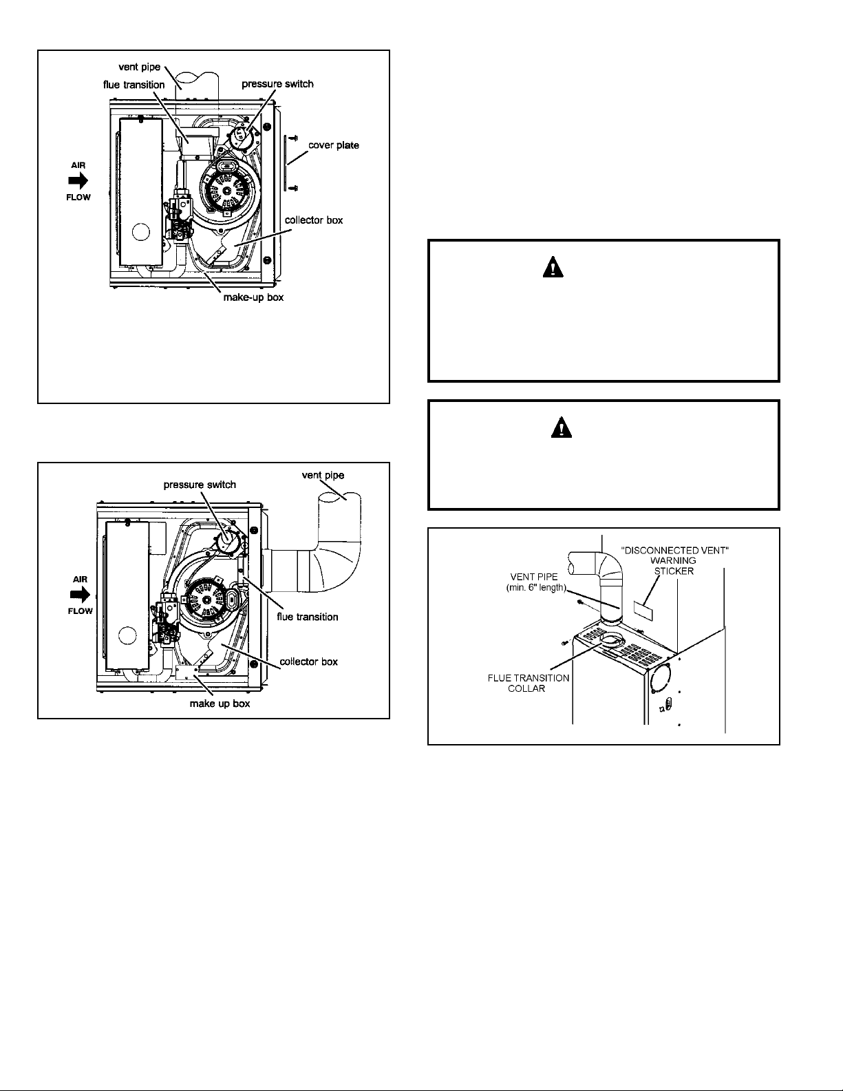
• Remove make-up box assembly (2 screws) and cut wire tie to
free make-up box wires. Reinstall make-up box on other side of
cabinet.
• Resecure make-up box wires: Either pull excess wires through
the blower compartment and secure using supplied wire tie, or
coil excess wire and secure to the gas manifold.
The venting tables in this manual were extracted from the
National Fuel Gas Code (NFPA 54 / ANSI Z223.1) and are
provided as a guide for proper vent installation. Proper
application, termination, construction and location of vents
must conform to local codes having jurisdiction. In the
absence of local codes, the NFGC serves as the dening
document.
Refer to the tables and the venting information contained
in these instructions to properly size and install the venting
system.
IMPORTANT
Once the venting system is installed, attach the
“Disconnected Vent” warning sticker to a visible area
of the plenum near the vent pipe. See Figure 23. The
warning sticker is provided in the bag assembly. Order
kit 66W04 for additional stickers.
Figure 21. Horizontal Right Position
Top Vent Discharge
Figure 22. Horizontal Right Position
Side Vent Discharge
These series units are classied as fan assisted Category
I furnaces when vertically vented according to the latest
edition of National Fuel Gas Code (NFPA 54 / ANSI
Z223.1) in the USA. A fan assisted Category I furnace is
an appliance equipped with an integral mechanical means
to either draw or force combustion products through the
combustion chamber and/or heat exchanger. This unit is
not approved for use with horizontal venting.
NOTE: Use these instructions as a guide. They do not
supersede local codes. This furnace must be vented
according to all local codes, these installation instructions,
and the provided venting tables in these instructions.
WARNING
Asphyxiation hazard. The exhaust vent for this furnace
must be securely connected to the furnace ue transition
at all times.
Figure 23. Vent Connection
Use self drilling sheet metal screws or a mechanical
fastener to rmly secure the vent pipe to the round collar of
the ue transition. If self drilling screws are used to attach
the vent pipe, it is recommended that three be used. Drive
one self drilling screw through the front and one through
each side of the vent pipe and collar. See Figure 23.
Install the rst vent connector elbow at a minimum of six
inches (152 mm) from the furnace vent outlet. See Figure
23.
Venting Using a Masonry Chimney
The following additional requirements apply when a lined
masonry chimney is used to vent this furnace.
507335-02Page 14 of 39 Issue 2128
Page 15
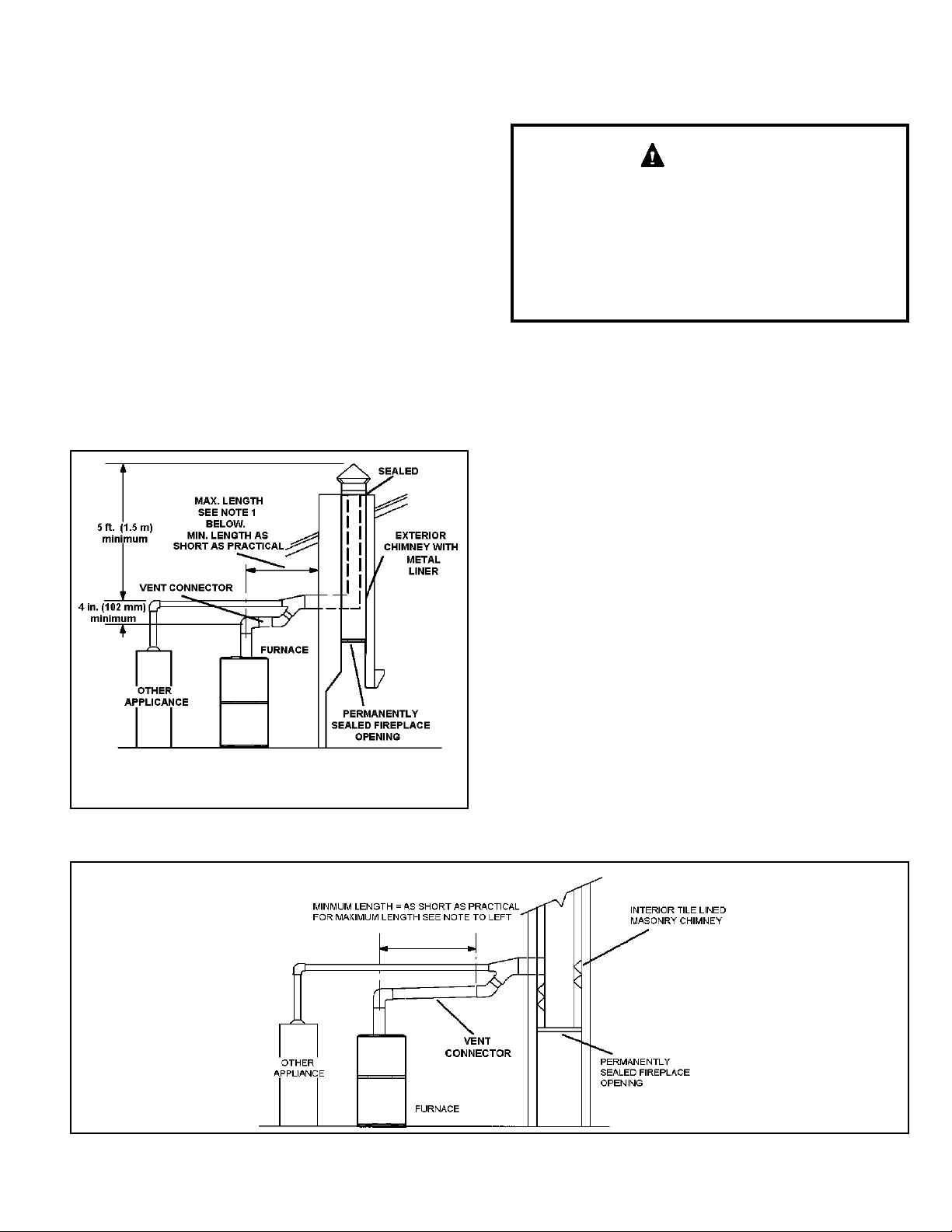
Masonry chimneys used to vent Category I central furnaces
must be either tile lined or lined with a listed metal lining
system or dedicated gas vent. Unlined masonry chimneys
are prohibited. See Figure 24 and Figure 25 for common
venting.
A chimney with one or more sides exposed to the outside
of the structure is considered to be an exterior chimney.
An exterior masonry chimney that is not tile lined must be
lined with B1 vent or a listed insulated exible metal vent.
An exterior tile lined chimney that is sealed and capped
may be lined with a listed uninsulated exible metal vent.
If the existing chimney will not accommodate a listed metal
liner, either the chimney must be rebuilt to accommodate
one of these liners or an alternate approved venting
method must be found.
Insulation for the exible vent pipe must be an encapsulated
berglass sleeve recommended by the exible vent pipe
manufacturer. See Figure 24.
DO NOT insulate the space between the liner and the
chimney wall with puffed mica or any other loose granular
insulating material.
IMPORTANT
SINGLE appliance venting of a fan assisted furnace into
a tile lined masonry chimney (interior or outside wall) is
prohibited. The chimney must rst be lined with either
type B1 vent or an insulated single wall exible vent
lining system which has been sized according to the
provided venting tables and the vent pipe manufacturer’s
instructions.
A fan assisted furnace may be commonly vented into an
existing lined masonry chimney if the following conditions
are met:
• The chimney is currently serving at least one drafthood
equipped appliance.
• The vent connectors and chimney are sized according
to the provided venting tables.
If type B1 double wall vent is used inside a chimney, no
other appliance can be vented into the chimney. The outer
wall of type B1 vent pipe must not be exposed to ue
products. A type B1 vent or masonry chimney liner shall
terminate above the roof surface with a listed cap or a listed
roof assembly according to the terms of their respective
listings and the vent manufacturer’s instructions.
NOTE 1: Refer to the provided venting tables for installations.
Refer to the capacity requirements shown in the provided
venting tables.
Figure 24. Common Venting Using Metal-Lined
Masonry Chimney
NOTE: Refer to provided
venting tables for installations.
When inspection reveals that an existing chimney is not
safe for the intended purpose, it shall be rebuilt to conform
to nationally recognized standards, lined or relined with
suitable materials, or replaced with a gas vent or chimney
suitable for venting. The chimney passageway must be
checked periodically to ensure that it is clear and free of
obstructions.
Do not install a manual damper, barometric draft regulator,
or ue restrictor between the furnace and the chimney.
NOTE: The chimney must be properly
sized per provided venting tables or lined
with listed metal lining system.
Figure 25. Common Venting Using Tile Lined Interior Masonry Chimney and Combined Vent Connector
507335-02 Page 15 of 39Issue 2128
Page 16
Never connect a Category I appliance to a chimney that is
servicing a solid fuel appliance. If a replace chimney ue
is used to vent this appliance, the replace opening must
be permanently sealed.
A type B or listed chimney lining system that passes through
an unused masonry chimney ue is not considered to be
exposed to the outdoors.
General Venting Requirements
Vent these furnaces according to these instructions:
3. Vent diameter recommendations and maximum
allowable piping runs are found in the provided venting
tables.
4. In no case should the vent or vent connector diameter
be less than the diameter specied in the provided
venting tables.
5. The minimum vent capacity determined by the sizing
tables must be less than the low re input rating and
the maximum vent capacity must be greater than the
high re input rating.
6. Single appliance vents - If the vertical vent or tile
lined chimney has a larger diameter or ow area than
the vent connector, use the vertical vent diameter to
determine the minimum vent capacity and the vent
connector diameter to determine the maximum vent
capacity. The ow area of the vertical vent, however,
shall not exceed 7 times the ow area of the listed
appliance categorized vent area, drafthood outlet
area or ue collar area unless designed according to
approved engineering methods.
7. Multiple appliance vents - The ow area of the largest
section of vertical vent or chimney shall not exceed 7
times the smallest listed appliance categorized vent
area, drafthood outlet area or ue collar area unless
designed according to approved engineering methods.
8. The entire length of single wall metal vent connector
shall be readily accessible for inspection, cleaning,
and replacement.
9. Single appliance venting congurations with zero
lateral lengths (Table 3 and Table 4) are assumed
to have no elbows in the vent system. For all other
vent congurations, the vent system is assumed to
have two 90° elbows. For each additional 90° elbow
or equivalent (for example two 45° elbows equal one
90° elbow) beyond two, the maximum capacity listed
in the venting table should be reduced by 10% (0.90 x
maximum listed capacity).
10. The common venting Tables (5, 6, 7, and 8) were
generated using a maximum horizontal vent connector
length of 1-1/2 feet (.46 m) for each inch (25 mm) of
connector diameter as follows:
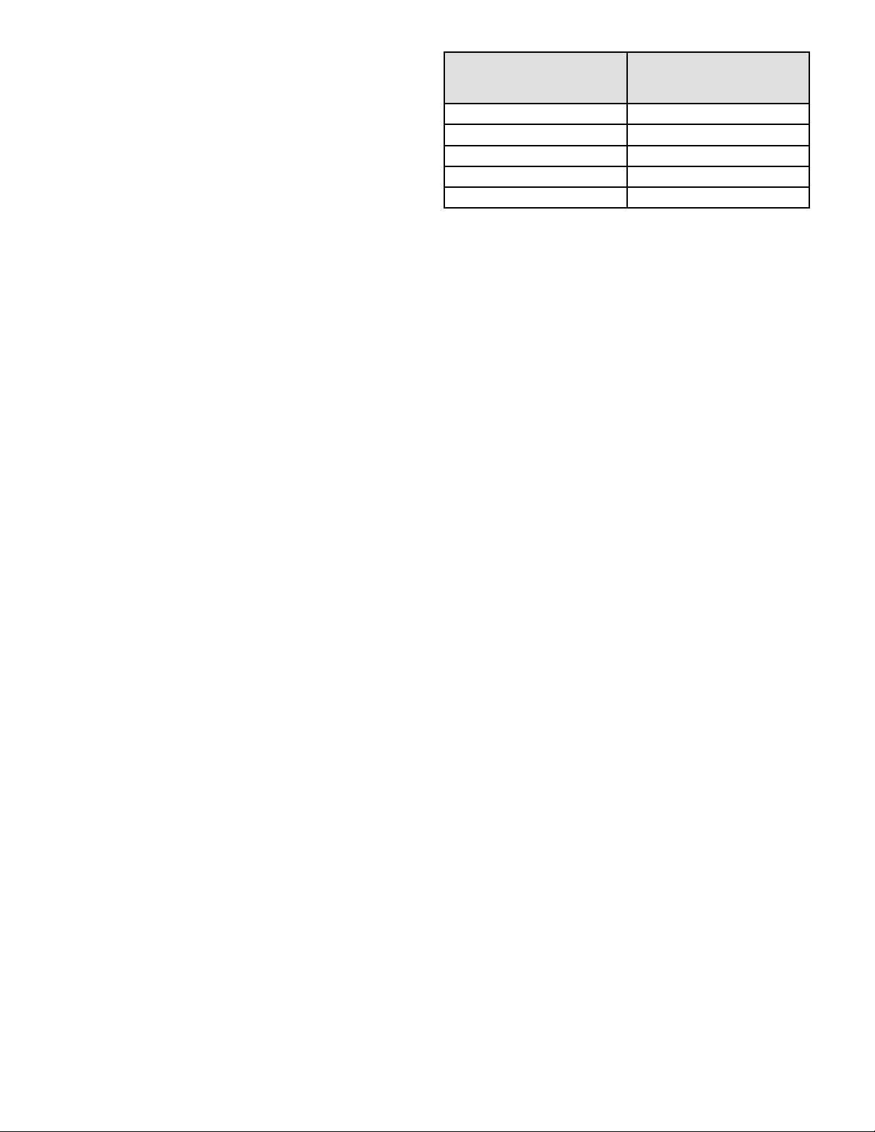
Connector Diameter
in. (mm)
3 (76) 4-1/2 (1.37)
4 (102) 6 (1.83)
5 (127) 7-1/2 (2.29)
6 (152) 9 (2.74)
7 (178) 10-1/2 (3.20)
Maximum Horizontal
Connector Length
ft. (m)
Table 2.
11. If the common vertical vent is offset, the maximum
common vent capacity listed in the common venting
tables should be reduced by 20%, the equivalent
of two 90° elbows (0.80 x maximum common vent
capacity). The horizontal length of the offset shall not
exceed 1-1/2 feet (.46 m) for each inch (25 mm) of
common vent diameter.
12. The vent pipe should be as short as possible with
the least number of elbows and angles required to
complete the job. Route the vent connector to the vent
using the shortest possible route.
13. A vent connector shall be supported without any dips
or sags and shall slope a minimum of 1/4 inch (6.4
mm) per linear foot (305 mm) of connector, back
toward the appliance.
14. Vent connectors shall be rmly attached to the furnace
ue collar by self drilling screws or other approved
means,except vent connectors of listed type B vent
material which shall be assembled according to the
manufacturer’s instructions. Joints between sections
of single wall connector piping shall be fastened by
screws or other approved means.
15. When the vent connector used for Category I
appliances must be located in or pass through a crawl
space, attic or other areas which may be cold, that
portion of the vent connector shall be constructed
of listed double wall type B vent material or material
having equivalent insulation qualities.
16. All venting pipe passing through oors, walls, and
ceilings must be installed with the listed clearance to
combustible materials and be re stopped according
to local codes. In absence of local codes, refer to
NFGC (2223.1 ).
17. No portion of the venting system can extend into, or
pass through any circulation air duct or plenum.
18. Vent connectors serving Category I appliances shall
not be connected to any portion of mechanical draft
systems operating under positive pressure such as
Category III or IV venting systems.
19. If vent connectors are combined prior to entering the
common vent, the maximum common vent capacity
listed in the common venting tables must be reduced
by 10%, the equivalent of one 90° elbow (0.90 x
maximum common vent capacity).
507335-02Page 16 of 39 Issue 2128
Page 17
20. The common vent diameter must always be at least as
large as the largest vent connector diameter.
21. In no case, shall the vent connector be sized more
than two consecutive table size diameters over the
size of the draft hood outlet or ue collar outlet.
22. Do not install a manual damper, barometric draft
regulator or ue restrictor between the furnace and
the chimney.
23. When connecting this appliance to an existing
dedicated or common venting system, you must
inspect the venting system’s general condition and
look for signs of corrosion. The existing vent pipe size
must conform to these instructions and the provided
venting tables. If the existing venting system does not
meet these requirements, it must be resized.
Removal of the Furnace from Common Vent
In the event that an existing furnace is removed from
a venting system commonly run with separate gas
appliances, the venting system is likely to be too large to
properly vent the remaining attached appliances.
Conduct the following test while each appliance is operating
and the other appliances (which are not operating) remain
connected to the common venting system. If the venting
system has been installed improperly, you must correct the
system as indicated in the general venting requirements
section.
3. Close all building doors and windows and all doors
between the space in which the appliances remaining
connected to the common venting system are located
and other spaces of the building. Turn on clothes
dryers and any appliances not connected to the
common venting system. Turn on any exhaust fans,
such as range hoods and bathroom exhausts, so they
will operate at maximum speed. Do not operate a
summer exhaust fan. Close replace dampers.
4. Follow the lighting instructions. Turn on the appliance
that is being inspected. Adjust the thermostat so that
the appliance operates continuously.
5. After the burners have operated for 5 minutes, test for
leaks of ue gases at the draft hood relief opening.
Use the ame of a match or candle.
6. After determining that each appliance connected to
the common venting system is venting properly, (step
3) return all doors, widows, exhaust fans, replace
dampers, and any other gas burning appliances to
their previous mode of operation.
7. If a venting problem is found during any of the
preceding tests, the common venting system must be
modied to correct the problem.
Resize the common venting system to the minimum vent
pipe size determined by using the appropriate tables in
Appendix G. (These are in the current standards of the
National Fuel Gas Code ANSI 2223.1.)
WARNING
CARBON MONOXIDE POISONING HAZARD
Failure to follow the steps outlined below for each
appliance connected to the venting system being
placed into operation could result in carbon monoxide
poisoning or death.
The following steps shall be followed for each appliance
connected to the venting system being placed into
operation, while all other appliances connected to the
venting system are not in operation:
1. Seal any unused openings in the common venting
system.
2. Inspect the venting system for proper size and
horizontal pitch. Determine that there is no blockage,
restriction, leakage, corrosion, or other deciencies
which could cause an unsafe condition.
507335-02 Page 17 of 39Issue 2128
Page 18
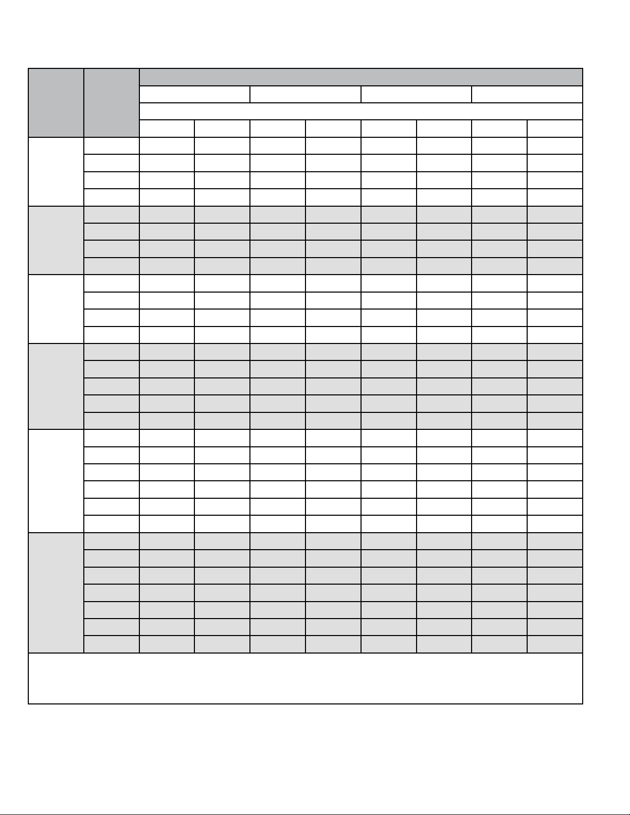
Capacity of Type B Double Wall Vents with Type B Double Wall Connectors Serving a Single Category I Appliance
Vent and Connector Diameter - D (inches)
Height H
(feet)
6
8
10
15
20
30
NOTE: Single appliance venting congurations with zero lateral lengths are assumed to have no elbows in the vent system. For
all other vent congurations, the vent system is assumed to have two 90 ° elbows. For each additional 90° elbow or equivalent (for
example two 45° elbows equal one 90° elbow) beyond two, the maximum capacity listed in the venting table should be reduced by 10
percent (0.90 x maximum listed capacity).
Lateral L
(feet)
0 0 78 0 152 0 251 0 375
2 13 51 18 97 27 157 32 232
4 21 49 30 94 39 153 50 227
6 25 46 36 91 47 149 59 223
0 0 84 0 165 0 276 0 415
2 12 57 16 109 25 178 28 263
5 23 53 32 103 42 171 53 255
8 28 49 39 98 51 164 64 247
0 0 88 0 175 0 295 0 447
2 12 61 17 118 23 194 26 289
5 23 57 32 113 41 187 52 280
10 30 51 41 104 54 176 67 267
0 0 94 0 191 0 327 0 502
2 11 69 15 136 20 226 22 339
5 22 65 30 130 39 219 49 330
10 29 59 40 121 51 206 64 315
15 35 53 48 112 61 195 75 301
0 0 97 0 202 0 349 0 540
2 10 75 14 149 18 250 20 377
5 21 71 29 143 38 242 47 367
10 28 64 38 133 50 229 62 351
15 34 58 46 124 59 217 73 337
20 48 52 55 116 69 206 84 322
0 0 100 0 213 0 374 0 587
2 9 81 13 166 14 283 18 432
5 21 77 28 160 36 275 45 421
10 27 70 37 150 48 262 59 405
15 33 64 44 141 57 249 70 389
20 56 58 53 132 66 237 80 374
30 NR NR 73 113 88 214 104 346
3 inch 4 inch 5 inch 6 inch
Appliance Input Rating in Thousands of Btu per Hour
MIN MAX MIN MAX MIN MAX MIN MAX
Table 3.
507335-02Page 18 of 39 Issue 2128
Page 19
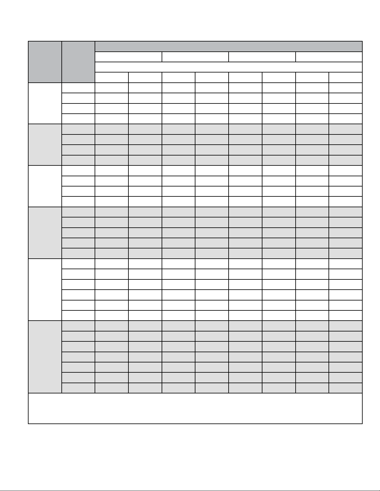
Capacity of Type B Double Wall Vents with Single Wall Metal Connectors Serving a Single Category I Appliance
Vent and Connector Diameter - D (inches)
Height H
(feet)
6
8
10
15
20
30
NOTE: Single appliance venting congurations with zero lateral lengths are assumed to have no elbows in the vent system. For
all other vent congurations, the vent system is assumed to have two 90 ° elbows. For each additional 90° elbow or equivalent (for
example two 45° elbows equal one 90° elbow) beyond two, the maximum capacity listed in the venting table should be reduced by 10
percent (0.90 x maximum listed capacity).
Lateral L
(feet)
0 38 77 59 151 85 249 126 373
2 39 51 60 96 85 156 123 231
4 NR NR 74 92 102 152 146 225
6 NR NR 83 89 114 147 163 220
0 37 83 58 164 83 273 123 412
2 39 56 59 108 83 176 121 261
5 NR NR 77 102 107 168 151 252
8 NR NR 90 95 122 161 175 243
0 37 87 57 174 82 293 120 444
2 39 61 59 117 82 193 11 9 287
5 52 56 76 111 105 185 148 277
10 NR NR 97 100 132 171 188 261
0 36 93 56 190 80 325 116 499
2 38 69 57 136 80 225 115 337
5 51 63 75 128 102 216 144 326
10 NR NR 95 11 6 128 201 182 308
15 NR NR NR NR 158 186 220 290
0 35 96 54 200 78 346 114 537
2 37 74 56 148 78 248 113 375
5 50 68 73 140 100 239 141 363
10 NR NR 93 129 125 223 177 344
15 NR NR NR NR 155 208 216 325
20 NR NR NR NR 186 192 254 306
0 34 99 53 211 76 372 11 0 584
2 37 80 55 164 76 281 109 429
5 49 74 72 157 98 271 136 417
10 NR NR 91 144 122 255 171 397
15 NR NR 11 5 131 151 239 208 377
20 NR NR NR NR 181 223 246 357
30 NR NR NR NR NR NR NR NR
3 inch 4 inch 5 inch 6 inch
Appliance Input Rating in Thousands of Btu per Hour
MIN MAX MIN MAX MIN MAX MIN MAX
Table 4.
507335-02 Page 19 of 39Issue 2128
Page 20
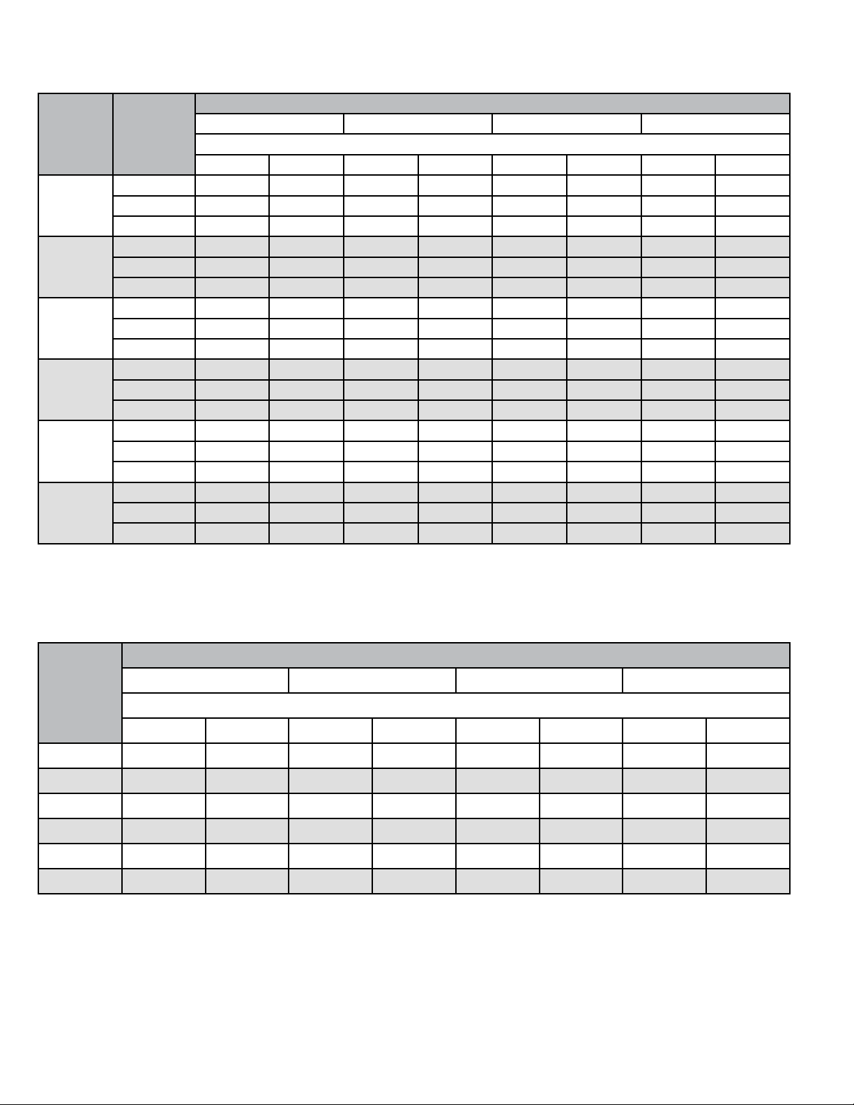
Vent Connector Capacity
Type B Double Wall Vents with Type B Double Wall Connectors Serving Two or More Category I Appliances
Vent and Connector Diameter - D (inches)
Vent
Height H
(feet)
6
8
10
15
20
30
Connector
Rise R
(feet)
1 22 37 35 66 46 106 58 164
2 23 41 37 75 48 121 60 183
3 24 44 38 81 49 132 62 199
1 22 40 35 72 49 114 64 176
2 23 44 36 80 51 128 66 195
3 24 47 37 87 53 139 67 210
1 22 43 34 78 49 123 65 189
2 23 47 36 86 51 136 67 206
3 24 50 37 92 52 146 69 220
1 21 50 33 89 47 142 64 220
2 22 53 35 96 49 153 66 235
3 24 55 36 102 51 163 68 248
1 21 54 33 99 46 157 62 246
2 22 57 34 105 48 167 64 259
3 23 60 35 110 50 176 66 271
1 20 62 31 113 45 181 60 288
2 21 64 33 118 47 190 62 299
3 22 66 34 123 48 198 64 309
3 inch 4 inch 5 inch 6 inch
Appliance Input Rating in Thousands of Btu per Hour
MIN MAX MIN MAX MIN MAX MIN MAX
Table 5.
Common Vent Capacity
Type B Double Wall Vents with Type B Double Wall Connectors Serving Two or More Category I Appliances
Common Vent Diameter
Vent Height
H (feet)
FAN + FAN FAN + NAT FAN + FAN FAN + NAT FAN + FAN FAN + NAT FAN + FAN FAN + NAT
6 92 81 140 116 204 161 309 248
8 101 90 155 129 224 178 339 275
10 110 97 169 141 243 194 367 299
15 125 112 195 164 283 228 427 352
20 136 123 215 183 314 255 475 394
30 152 138 244 210 361 297 547 459
4 inch 5 inch 6 inch 7 inch
Appliance Input Rating in Thousands of Btu per Hour
Table 6.
507335-02Page 20 of 39 Issue 2128
Page 21
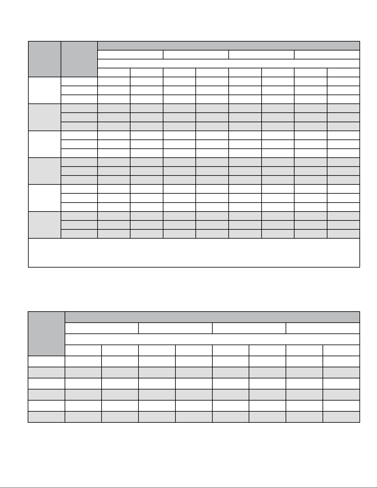
Vent Connector Capacity
Type B Double Wall Vents with Single Wall Metal Connectors Serving Two or More Category I Appliances
Vent and Connector Diameter - D (inches)
Vent
Height H
(feet)
6
8
10
15
20
30
NOTE: Single appliance venting congurations with zero lateral lengths are assumed to have no elbows in the vent system. For
all other vent congurations, the vent system is assumed to have two 90 ° elbows. For each additional 90° elbow or equivalent (for
example two 45° elbows equal one 90° elbow) beyond two, the maximum capacity listed in the venting table should be reduced by 10
percent (0.90 x maximum listed capacity).
Lateral L
(feet)
1 NR NR NR NR NR NR NR NR
2 NR NR NR NR NR NR 168 182
3 NR NR NR NR 121 131 175 198
1 NR NR NR NR NR NR NR NR
2 NR NR NR NR 125 126 184 193
3 NR NR NR NR 130 138 191 208
1 NR NR NR NR 119 121 182 186
2 NR NR 84 85 124 134 189 203
3 NR NR 89 91 129 144 197 217
1 NR NR 79 87 116 138 177 214
2 NR NR 83 94 121 150 185 230
3 NR NR 87 100 127 160 193 243
1 49 56 78 97 115 152 175 238
2 52 59 82 103 120 163 182 252
3 55 62 87 107 125 172 190 264
1 47 60 77 110 112 175 169 278
2 51 62 81 115 117 185 177 290
3 54 64 85 119 122 193 185 300
3 inch 4 inch 5 inch 6 inch
Appliance Input Rating in Thousands of Btu per Hour
MIN MAX MIN MAX MIN MAX MIN MAX
Table 7.
Common Vent Capacity
Type B Double Wall Vents with Single Wall Metal Connectors Serving Two or More Category I Appliances
Common Vent Diameter
Vent Height
H (feet)
FAN + FAN FAN + NAT FAN + FAN FAN + NAT FAN + FAN FAN + NAT FAN + FAN FAN + NAT
6 NA 78 NA 113 200 158 304 244
8 NA 87 NA 126 218 173 331 269
10 NA 94 163 137 237 189 357 292
15 121 108 189 159 275 221 416 343
20 131 118 208 177 305 247 463 383
30 145 132 236 202 350 286 533 446
4 inch 5 inch 6 inch 7 inch
Appliance Input Rating in Thousands of Btu per Hour
Table 8.
507335-02 Page 21 of 39Issue 2128
Page 22
Gas Piping
CAUTION
If a exible gas connector is required or allowed by
the authority that has jurisdiction, black iron pipe shall
be installed at the gas valve and extend outside the
furnace cabinet. The exible connector can then be
added between the black iron pipe and the gas supply
line.
Gas Supply
1. This unit is shipped standard for left or right side
installation of gas piping (or top entry in horizontal
applica tions). Connect the gas supply to the piping
assembly.
2. When connecting the gas supply piping, consider
factors such as length of run, number of ttings, and
furnace rating to avoid excessive pressure drop. Table
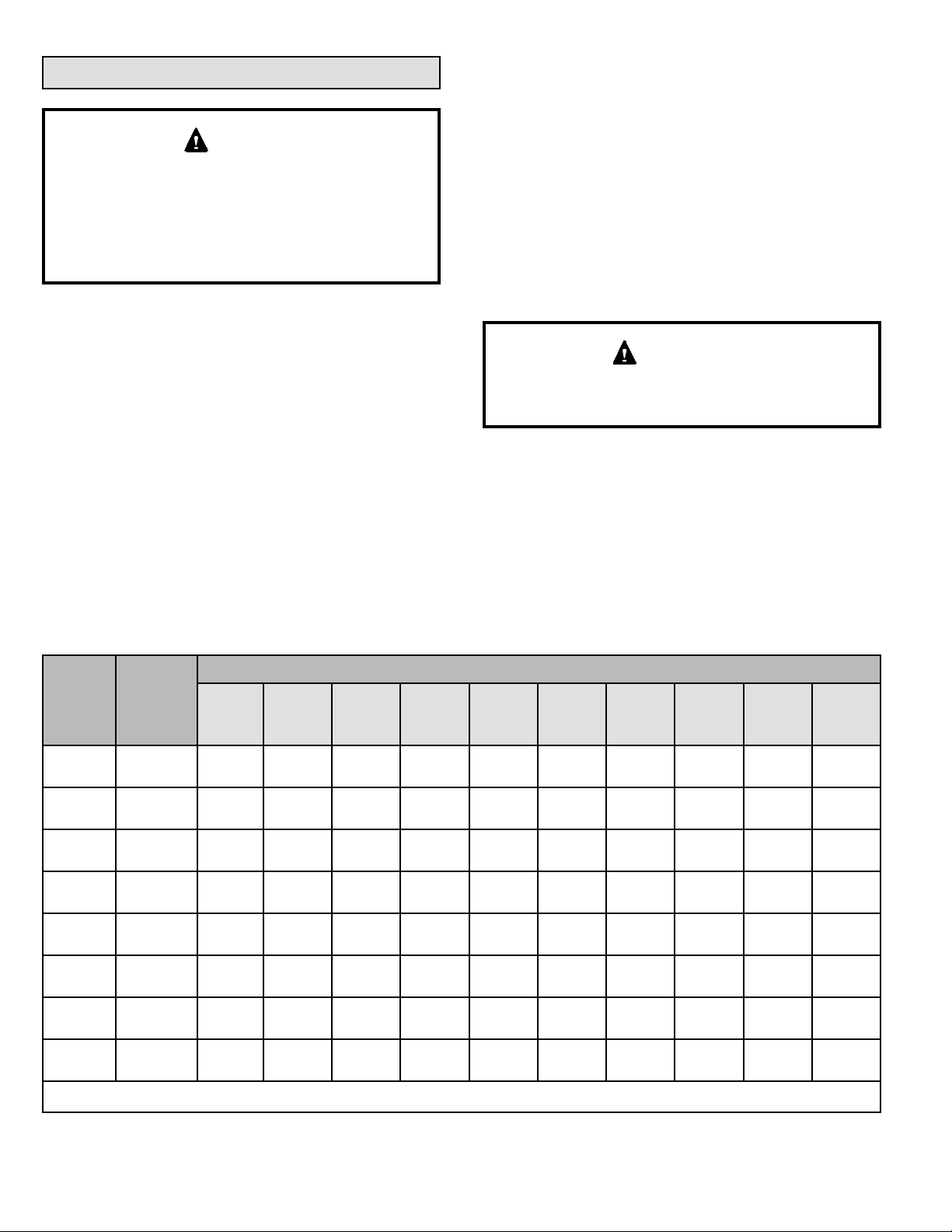
9 lists recommended pipe sizes for typical applications.
3. The gas piping must not run in or through air ducts,
clothes chutes, gas vents or chimneys, dumb waiters,
or elevator shafts.
4. The piping should be sloped 1/4 inch (6.4 mm) per
15 feet (4.57 m) upward toward the meter from the
furnace. The piping must be supported at proper
intervals [every 8 to 10 feet (2.44 to 3.01 m)] with
suitable hangers or straps. Install a drip leg in vertical
pipe runs to the unit.
5. A 1/8” N.P.T. plugged tap or pressure post is located
on the gas valve to facilitate test gauge connection.
See Figure 28.
6. In some localities, codes may require the installation
of a manual main shut off valve and union (furnished
by the installer) external to the unit. The union must be
of the ground joint type.
IMPORTANT
Compounds used on threaded joints of gas piping must
be resistant to the actions of liquied petroleum gases.
NOTE: If emergency shutoff is necessary, shut off the
main manual gas valve and disconnect main power to the
furnace. The installer should properly label these devices.
Nominal
Iron Pipe
Size
inches
(mm)
1/2
(12.7)
3/4
(19.05)
1
(25.4)
1-1/4
(31.75)
1-1/2
(38.1)
2
(50.8)
2-1/2
(63.5)
3
(76.2)
Internal
Diameter
inches
(mm)
.622
(17.799)
.824
(20.930)
1.049
(26.645)
1.380
(35.052)
1.610
(40.894)
2.067
(52.502)
2.469
(67.713)
3.068
(77.927)
10
(3.048)
175
(4.96)
360
(10.19)
680
(919.25)
1400
(39.64)
2100
(59.46)
3950
(111.85)
6300
(178.39)
11000
(311.48)
20
(6.096)
120
(3.40)
250
(7.08)
465
(13.17)
950
(26.90)
1460
(41.34)
2750
(77.87)
4350
(123.17)
7700
(218.03)
Gas Pipe Capacity - ft³/hr (m³/hr)
Length of Pipe - feet (m)
30
(9.144)
97
(2.75)
200
(5.66)
375
(10.62)
770
(21.80)
1180
(33.41)
2200
(62.30)
3520
(99.67)
6250
(176.98)
40
(12.192)
82
(2.32)
170
(4.81)
320
(9.06)
660
(18.69)
990
(28.03)
1900
(53.80)
3000
(84.95)
5300
(150.07)
50
(15.240)
73
(2.07)
151
(4.28)
285
(8.07)
580
(16.42)
900
(25.48)
1680
(47.57)
2650
(75.04)
4750
(134.50)
(18.288)
(1.87)
(3.91)
260
(7.36)
530
(15.01)
810
(22.94)
1520
(43.04)
2400
(67.96)
4300
(121.76)
60
66
138
70
(21.336)
61
(1.73)
125
(3.54)
240
(6.80)
490
(13.87)
750
(21.24)
1400
(39.64)
2250
(63.71)
3900
(110.43)
80
(24.384)
57
(1.61)
118
(3.34)
220
(6.23)
460
(13.03)
690
(19.54)
1300
(36.81)
2050
(58.05)
3700
(104.77)
90
(27.432)
53
(1.50)
110
(3.11)
205
(5.80)
430
(12.18)
650
(18.41)
1220
(34.55)
1950
(55.22)
3450
(97.69)
100
(30.480)
50
(1.42)
103
(2.92)
195
(5.52)
400
(11.33)
620
(17.56)
1150
(32.56)
1850
(52.38)
3250
(92.03)
Note: Capacity given in cubic feet (m³) of gas per hour and based on 0.60 specic gravity gas.
Table 9.
507335-02Page 22 of 39 Issue 2128
Page 23
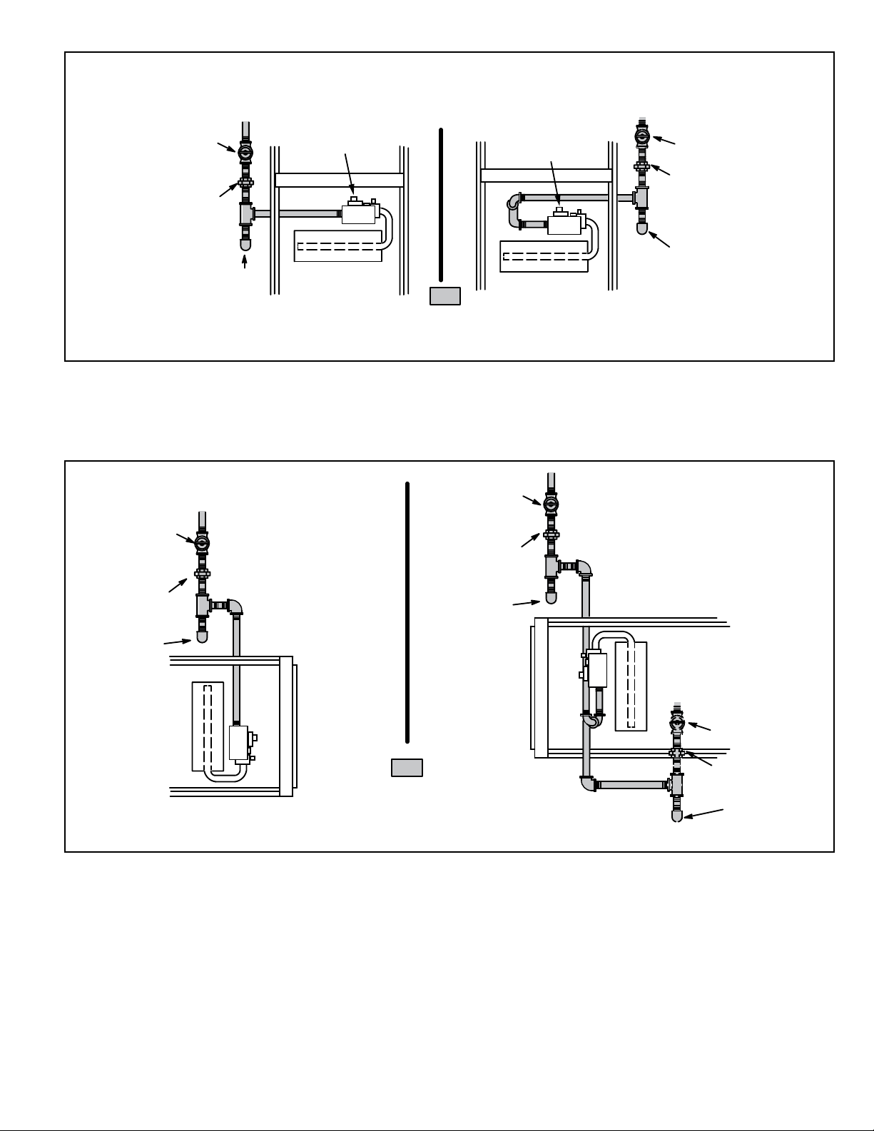
FIELD
PROVIDED
AND INSTALLED
Left Side Piping
(Standard)
Right Side Piping
(Alternate)
GROUND
JOINT
UNION
DRIP LEG
MANUAL
MAIN SHUT-OFF
VALV E
AUTOMATIC
GAS VALVE
(with manual
shut-off valve)
GROUND
JOINT
UNION
DRIP LEG
MANUAL
MAIN SHUT-OFF
VALV E
AUTOMATIC
GAS VALVE
(with manual
shut-off valve)
MANUAL
MAIN SHUT-OFF
VALV E
NOTE: BLACK IRON PIPE ONLY TO BE ROUTED INSIDE OF CABINET
Figure 26. Upow Applications
Possible Gas Piping Congurations
MANUAL
Horizontal Application
Right-Side Air Discharge
MAIN SHUT-OFF
VALV E
GROUND
JOINT
UNION
Horizontal Application
Left-Side Air Discharge
GROUND
JOINT
UNION
DRIP LEG
DRIP LEG
FIELD
PROVIDED
AND INSTALLED
NOTE: BLACK IRON PIPE ONLY TO BE ROUTED INSIDE OF CABINET
Figure 27. Horizontal Applications
Possible Gas Piping Congurations
MANUAL
MAIN SHUT-OFF
VALV E
GROUND
JOINT
UNION
DRIP LEG
507335-02 Page 23 of 39Issue 2128
Page 24
Leak Check
After gas piping is completed, carefully check all eldinstalled piping connections for gas leaks. Use a
commercially available leak detecting solution specically
manufactured for leak detection. Never use an open ame
to test for gas leaks.
Electrical
ELECTROSTATIC DISCHARGE (ESD)
Precautions and Procedures
The furnace must be isolated from the gas supply
system by closing the individual manual shut-off valve
during any gas supply system at pressures greater than
or equal to 1/2 psig (3.48 kPa, 14 inches w.c.). This
furnace and its components are designed, manufactured
and independently certied to comply with all applicable
ANSI/CSA standards. A leak check of the furnace and its
components is not required.
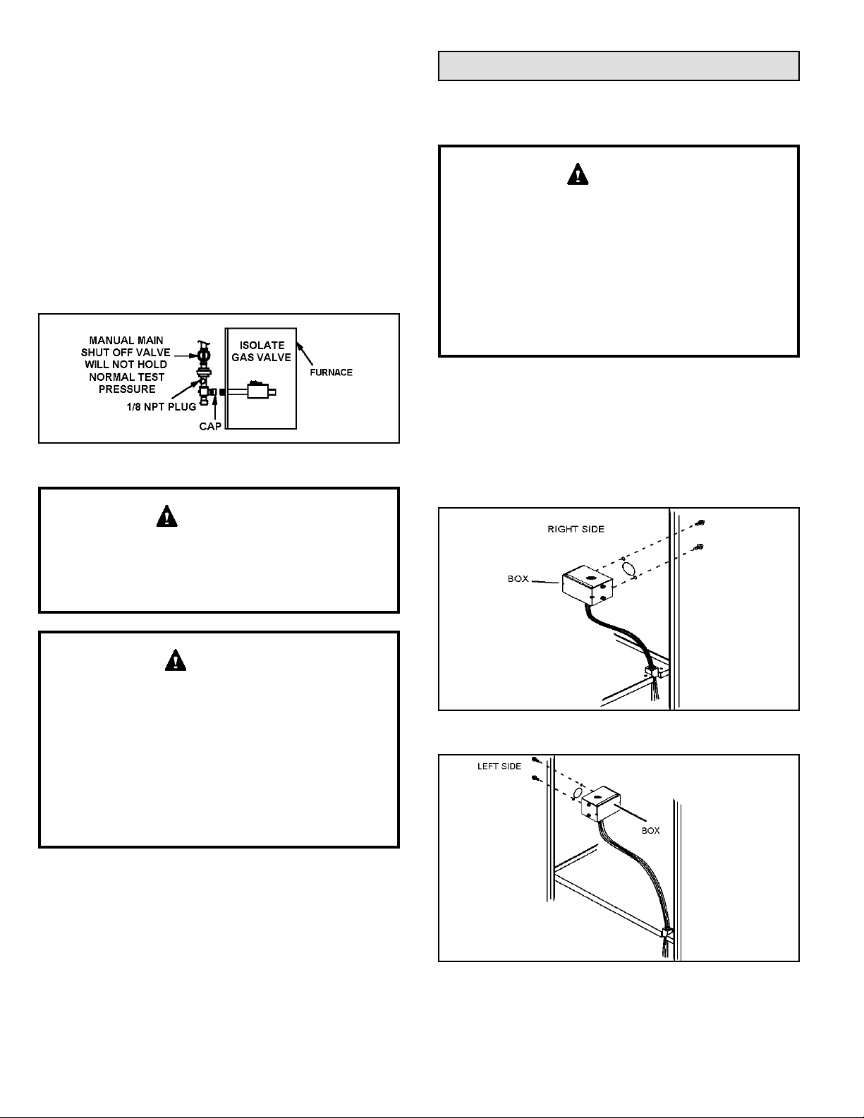
Figure 28.
IMPORTANT
When testing pressure of gas lines, gas valve must be
disconnected and isolated. See Figure 28. Gas valves
can be damaged if subjected to pressures greater than
1/2 psig (3.48 kPa, 14 inches w.c.).
CAUTION
Electrostatic discharge can affect electronic components.
Take precautions during furnace installation and service
to protect the furnace’s electronic controls. Precautions
will help to avoid control exposure to electrostatic
discharge by putting the furnace, the control and the
technician at the same electrostatic potential. Neutralize
electrostatic charge by touching hand and all tools on
an unpainted unit surface, such as the gas valve or
blower deck, before performing any service procedure.
The unit is equipped with a eld make-up box on the left
hand side of the cabinet. The make-up box may be moved
to the right side of the furnace to facilitate installation. If
the make-up box is moved to the right side, clip the wire
ties that bundle the wires together. The excess wire must
be pulled into the blower compartment. Secure the excess
wire to the existing harness to protect it from damage.
WARNING
FIRE OR EXPLOSION HAZARD
Failure to follow the safety warnings exactly could
result in serious injury, death, or property damage.
Never use an open ame to test for gas leaks. Check
all connections using a commercially available soap
solution made specically for leak detection. Some
soaps used for leak detection are corrosive to certain
metals. Carefully rinse piping thoroughly after leak test
has been completed.
Figure 29. Interior Make-Up Box Installation
Figure 30. Interior Make-Up Box Installation
507335-02Page 24 of 39 Issue 2128
Page 25
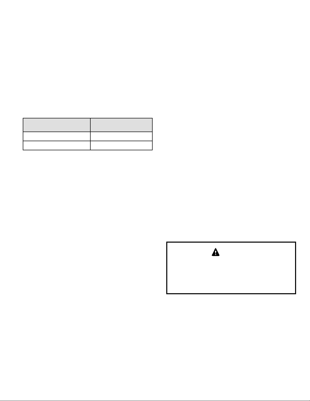
Refer to Figure 44 for schematic wiring diagram and
troubleshooting and Figure 43 for eld wiring.
1. The power supply wiring must meet Class I restrictions.
Protected by either a fuse or circuit breaker, select
circuit protection and wire size according to unit
nameplate.
NOTE: Unit nameplate states maximum current draw.
Maximum over current protection allowed is shown in
Table 10.
2. Holes are on both sides of the furnace cabinet to
facilitate wiring.
3. Install a separate (properly sized) disconnect switch
near the furnace so that power can be turned off for
servicing.
Capacity
Maximum Over-Current
Protection (Amps)
9. Install the room thermostat according to the instructions
provided with the thermostat. If the furnace is being
matched with a heat pump, refer to the instruction
packaged with the dual fuel thermostat.
Indoor Blower Speeds
1. When the thermostat is set to “FAN ON,” the indoor
blower will run continuously at approximately 50%
of the second stage cooling speed when there is no
cooling or heating demand. See Table 12 for allowable
continuous circulation speeds.
2. When this unit is running in the heating mode, the
indoor blower will run on the heating speed designated
by the positions of DIP switches 1 (A,B,C,D) of the
HEAT jumper plug.
3. When there is a cooling demand, the indoor blower will
run on the cooling speed designated by the positions
of DIP switches (A, B, C, D) of the COOL jumper plug.
070AV12 15
090BV16, 110CV20 20
Table 10.
4. Before connecting the thermostat, check to make sure
the wires will be long enough for servicing at a later
date. Make sure that thermostat wire is long enough to
facilitate future removal of blower for service.
5. Complete the wiring connections to the equipment.
Use the provided unit wiring diagram and the eld
wiring diagram shown in Figure 43. Use 18 gauge
wire or larger that is suitable for Class II rating for
thermostat connections.
6. Electrically ground the unit according to local codes or,
in the absence of local codes, according to the current
National Electric Code (ANSI/NFPA No. 70). A green
ground wire is provided in the eld make-up box.
NOTE: This furnace contains electronic components
that are polarity sensitive. Make sure that the furnace
is wired correctly and is properly grounded.
7. One line voltage “ACC” 1/4” spade terminal is provided
on the furnace integrated control. Any electronic air
cleaner or other accessory rated up to one amp can
be connected to this terminal with the neutral leg of the
circuit being connected to one of the provided neutral
terminals. See Figure 43 for control conguration.
This terminal is energized when the indoor blower is
operating.
8. One line voltage “HUM” 1/4” spade terminal is provided
on the furnace integrated control. Any humidier rated
up to one amp can be connected to this terminal with
the neutral leg of the circuit being connected to one
of the provided neutral terminals. See Figure 43 for
control conguration. This terminal is energized in the
heating mode whenever the combustion air inducer is
operating.
Generator Use - Voltage Requirements
The following requirements must be kept in mind when
specifying a generator for use with this equipment:
• The furnace requires 120 volts ± 10% (Range: 108
volts to 132 volts).
• The furnace operates at 60 Hz ± 5% (Range: 57 Hz
to 63 Hz).
• The furnace integrated control requires both polarity
and proper ground. Both polarity and proper grounding
should be checked before attempting to operate the
furnace on either permanent or temporary power.
• Generator should have a wave form distortion of less
than 5% RHD.
Electrical Wiring
WARNING
Risk of electrical shock. Disconnect electrical power
at the circuit breaker or service panel before making
electrical connections. Failure to disconnect power
supplies can result in property damage, personal injury,
or death.
The furnace must be grounded and wired in accordance
with local codes or, in the absence of local codes, with the
National Electrical Code ANSI/NFPA No. 70 (latest edition)
and/or CSA C22.1 Electrical Code (latest edition) if an
external electrical source is utilized.
In all instances, other than wiring for the thermostat,
the wiring to be done and any replacement of wire shall
conform with the temperature limitation for Type T wire
–63°F (35°C) rise.
507335-02 Page 25 of 39Issue 2128
Page 26
Connect a sufciently sized wire with ground to the
furnace’s line voltage connections and ground wire. Refer
to the furnace rating plate for electrical characteristics
to be used in sizing eld supply wiring and overcurrent
protection.
Terminals are provided on the integrated ignition/blower
control board for connection to a 120-volt humidier. The
“HUM” terminal is energized whenever the thermostat
calls for heat. See the furnace wiring diagram for specic
connection information.
The line voltage supply should be routed through a readily
accessible disconnect located within sight of the furnace. A
junction box on the furnace side panel is provided for line
voltage connections. Refer to the furnace wiring diagram
for specic connection information.
Proper polarity of the supply connections (“HOT” and
“NEUTRAL”) must be observed to ensure that safety
controls provide the protection intended.
A connection to the unit’s ground wire and actual earth
ground (typically a ground stake or buried steel pipe) must
be maintained for proper operation.
Thermostat
Install a room thermostat according to the instructions
furnished with it. Select a location on an inside wall that
is not subject to drafts, direct sunshine, or other heat
sources. The initial heat anticipator setting should be equal
to the total current draw of the control circuit. Low voltage
thermostat connections are to be made to the integrated
ignition/blower control board as indicated on the wiring
diagram.
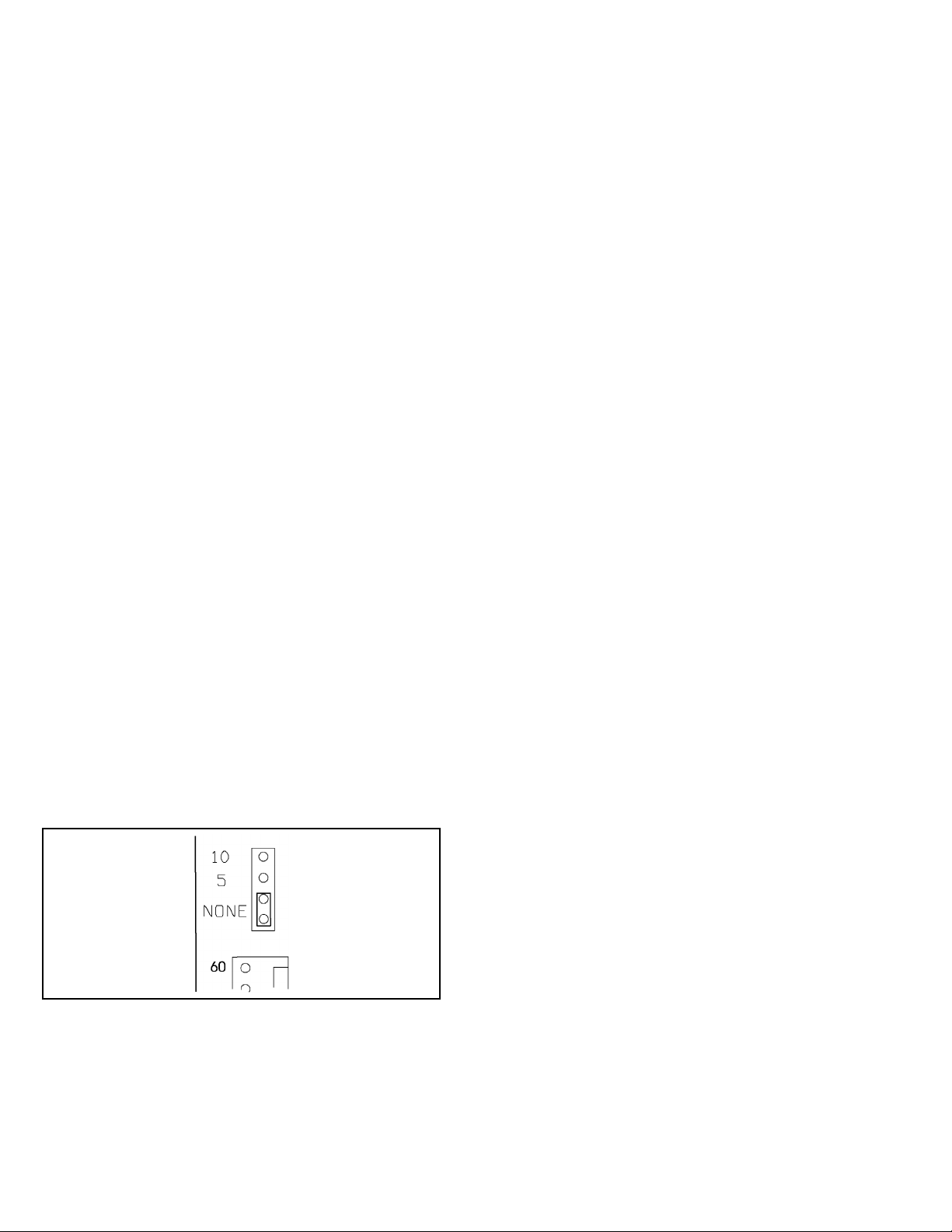
Single Stage Thermostat Operation (80G2UH-V )
The automatic heat staging option allows a single stage
thermostat to be used with two stage furnace models
(80G2UH-V). To activate this option, move the jumper
pin (see Figure 31) to desired setting (5 minutes or 10
minutes). The furnace will start on 1st stage heat and
stay at 1st stage heat for the duration of the selected time
before switching to 2nd stage heat.
W1 on the control board must be connected to W1 on the
thermostat.
Electronic Air Cleaner
Terminals are provided on the integrated ignition/blower
control board for connection of a 120-volt electronic air
cleaner. The “EAC” terminal is energized whenever the
thermostat calls for heat, cooling, or continuous blower. See
furnace wiring diagram for specic connection information.
Variable Speed Features
This furnace is equipped with a variable speed circulation
air blower motor that will deliver a constant airow within a
wide range of external static pressures. Other features of
this variable speed motor include:
Soft Start
The variable speed motor will slowly ramp up to normal
operating speed. This minimizes noise and increases
comfort by eliminating the initial blasts of air encountered
with standard motors.
Soft Stop
At the end of a cooling or heating cycle, the variable speed
motor will slowly ramp down after a short blower “off” delay.
If continuous blower operation has been selected, the
variable speed motor will slowly ramp down until it reaches
the airow for that mode.
Passive and Active Dehumidication
Passive Dehumidication
For situations where humidity control is a problem, a
dehumidication feature has been built into the variable
speed motor. At the start of each cooling cycle, the variable
speed motor will run at 82% of the rated airow for 7.5
minutes. After 7.5 minutes has elapsed, the motor will
increase to 100% of the rated airow.
Figure 31. Automatic Heat Staging Jumper
Humidier
Active Dehumidication
To achieve additional dehumidication, clip the jumper
wire located below the DEHUM terminal on the integrated
ignition/blower control board and connect a humidity
control that opens on humidity rise to the DEHUM and
R terminals. The DEHUM terminal on the control board
must be connected to the normally closed contact of the
humidity control so that the board senses an open circuit
on high humidity. In this setup, the variable speed motor
will operate at a 18% reduction in the normal cooling airow
rate when there is a call for dehumidication.
Both the passive and active dehumidication methods
described above can be utilized on the same furnace.
507335-02Page 26 of 39 Issue 2128
Page 27
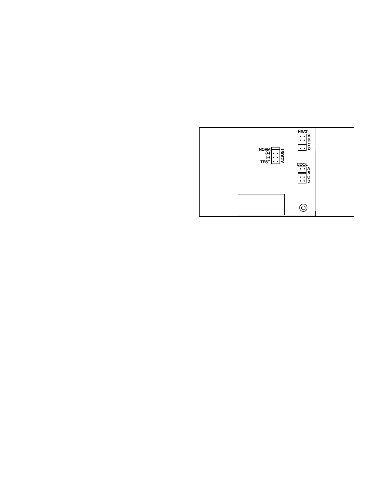
Circulating Airow Adjustments
Cooling Mode
The units are factory set for the highest airow for each
model. Adjustments can be made to the cooling airow
by repositioning the jumper plug marked COOL – A, B,
C, D (see Figure 32) based on the information found in
the Adjusting Airow tables. To determine what CFM the
motor is delivering at any time, count the number of times
the amber LED on the control board ashes. Each ash
signies 100 CFM; count the ashes and multiply by 100
to determine the actual CFM delivered (for example: 10
ashes x 100 = 1000 CFM).
Heating Mode
These units are factory set to run at the middle of the heating
rise range as shown on the unit rating plate. If higher or
lower rise is desired, reposition the jumper plug marked
HEAT - A, B, C, D (see Figure 32) based on the information
found in the Adjusting Airow tables. To determine what
CFM the motor is delivering at any time, count the number
of times the amber LED on the control board ashes. Each
ash signies 100 CFM; count the ashes and multiply by
100 to determine the actual CFM delivered (for example:
10 ashes x 100 = 1000 CFM).
Continuous Blower Operation
The comfort level of the living space can be enhanced
when using this feature by allowing continuous circulation
of air between calls for cooling or heating. The circulation
of air occurs at half the full cooling airow rate.
To engage the continuous blower operation, place the
fan switch on the thermostat into the ON position. A call
for fan from the thermostat closes R to G on the ignition
control board. The control waits for a 1 second thermostat
debounce delay before responding to the call for fan by
ramping the circulating blower up to 50% of the cooling
speed. When the call for continuous fan is satised, the
control immediately ramps down the circulating blower.
Adjust Tap
Airow amounts may be increased or decreased by 10%
by moving the ADJUST jumper plug (see Figure 32) from
the NORM position to the (+) or (-) position. Changes to the
ADJUST tap will affect both cooling and heating airows.
The TEST position on the ADJUST tap is not used.
Figure 32. ADJUST, HEAT, and COOL Taps on
Integrated Ignition/Blower Control Board
507335-02 Page 27 of 39Issue 2128
Page 28
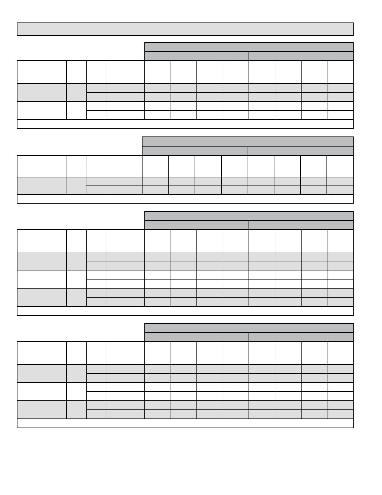
Adjusting Airow
Heating CFM @ 0 through 0.8” w.c. Cooling CFM @ 0 through 0.8” w.c.
Model
80G2UH070AV12 1/2
80G2UH090BV16 1
* Speed Adjustment (+) or (-) 10% by moving jumper from NORM.
Model
80G2UH110CV20 1
* Speed Adjustment (+) or (-) 10% by moving jumper from NORM.
Motor
Hp
Motor
Hp
Stage
2nd Norm 715 900 934 1026 920 985 1105 1225
1st Norm 679 754 842 937 690 735 795 885
2nd Norm 1013 1079 1130 1390 940 1200 1405 1600
1st Norm 926 996 1033 1271 600 810 960 1090
Stage
2nd Norm 1288 1405 1489 1543 1401 1564 1714 1877
1st Norm 1178 1301 1361 1410 969 1075 1181 1336
Speed
Adjustment*
Speed
Adjustment*
Heat
Setting
A
Bottom Return Air, Return Air from Both Sides or Return Air from Bottom and One Side
Heating CFM @ 0 through 0.8” w.c. Cooling CFM @ 0 through 0.8” w.c.
Heat
Setting
A
Heat
Setting
B
Heat
Setting
B
Heat
Setting
C
Heat
Setting
C
Bottom Return Air
Heat
Setting
D
Heat
Setting
D
Cool
Setting
A
Cool
Setting
A
Cool
Setting
B
Cool
Setting
B
Cool
Setting
C
Cool
Setting
C
Cool
Setting
D
Cool
Setting
D
Heating CFM @ 0 through 0.8” w.c. Cooling CFM @ 0 through 0.8” w.c.
Model
80G2UH070AV12 1/2
80G2UH090BV16 1
80G2UH110CV20 1
* Speed Adjustment (+) or (-) 10% by moving jumper from NORM.
Model
80G2UH070AV12 1/2
80G2UH090BV16 1
80G2UH110CV20 1
* Speed Adjustment (+) or (-) 10% by moving jumper from NORM.
Motor
Hp
Motor
Hp
Stage
2nd Norm 707 890 925 1013 926 1003 1104 1213
1st Norm 673 750 864 949 689 726 795 859
2nd Norm 1013 1075 1130 1394 897 1158 1346 1499
1st Norm 926 996 1033 1271 571 778 930 1040
2nd Norm 1277 1368 1447 1501 1375 1526 1687 1843
1st Norm 1169 1250 1323 1382 942 1048 1154 1277
Stage
2nd Norm n/a n/a n/a n/a n/a n/a n/a n/a
1st Norm n/a n/a n/a n/a n/a n/a n/a n/a
2nd Norm 1017 1079 1140 1390 904 1126 1347 1525
1st Norm 930 981 1045 1277 599 762 928 1045
2nd Norm 1280 1367 1431 1505 1469 1536 1654 1813
1st Norm 1174 1252 1318 1385 1008 1038 1159 1307
Speed
Adjustment*
Speed
Adjustment*
Heat
Setting
A
Heating CFM @ 0 through 0.8” w.c. Cooling CFM @ 0 through 0.8” w.c.
Heat
Setting
A
Heat
Setting
B
Heat
Setting
B
Single Side Return Air
Heat
Setting
C
Side Return with Optional Return Air Base
Heat
Setting
C
Heat
Setting
D
Heat
Setting
D
Cool
Setting
A
Cool
Setting
A
Cool
Setting
B
Cool
Setting
B
Cool
Setting
C
Cool
Setting
C
Cool
Setting
D
Cool
Setting
D
507335-02Page 28 of 39 Issue 2128
Page 29
Allowable Heating Speeds
Model Speed Adjust Setting "D" Setting "C" Setting "B" Setting "A"
+10% Allowed Allowed Allowed Not Allowed
80G2UH070AV12
80G2UH090BV16
80G2UH110CV20
Norm Allowed Allowed Factory Setting Allowed
-10% Allowed Allowed Allowed Allowed
+10% Allowed Allowed Allowed Not Allowed
Norm Allowed Allowed Factory Setting Not Allowed
-10% Allowed Allowed Allowed Allowed
+10% Allowed Allowed Allowed Not Allowed
Norm Allowed Allowed Factory Setting Allowed
-10% Allowed Allowed Allowed Allowed
Table 11.
Allowable Circulation Speeds
Model 38% of Second Stage Cooling
All Models Factory Setting
Table 12.
Start-Up
For Your Safety, Read Before Operating
WARNING
Do not use this furnace if any part has been under
water. Immediately call a licensed professional service
technician (or equivalent) to inspect the furnace and
to replace any part of the control system and any gas
control which has been under water.
WARNING
If overheating occurs or if gas supply fails to shut off,
shut off the manual gas valve to the appliance before
shutting off electrical supply.
CAUTION
Before attempting to perform any service or
maintenance, turn the electrical power to unit OFF at
disconnect switch.
WARNING
During blower operation, the ECM motor emits
energy that may interfere with pacemaker operation.
Interference is reduced by both the sheet metal cabinet
and distance.
BEFORE LIGHTING smell all around the appliance area
for gas. Be sure to smell next to the oor because some
gas is heavier than air and will settle on the oor.
The gas valve on this unit is equipped with a gas control
switch. Use only your hand to move the switch. Never use
tools. If the switch will not turn or if the control switch will
not move by hand, do not try to repair it.
Placing the Furnace into Operation
These units are equipped with an automatic ignition
system. Do not attempt to manually light burners on these
furnaces. Each time the thermostat calls for heat, the
burners will automatically light. The ignitor does not get hot
when there is no call for heat on units with an automatic
ignition system.
WARNING
507335-02 Page 29 of 39Issue 2128
If you do not follow these instructions exactly, a re
or explosion may result causing property damage,
personal injury, or loss of life.
Page 30
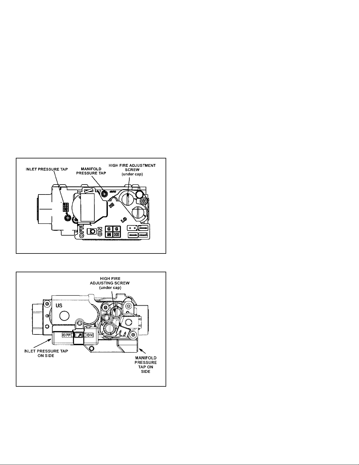
Gas Valve Operation
See Figure 33 and Figure 34
1. STOP! Read the safety information at the beginning
of this section.
2. Set the thermostat to the lowest setting.
3. Turn OFF all electrical power to the unit.
4. This furnace is equipped with an ignition device which
automatically lights the burners. Do not try to light the
burners by hand.
5. Remove the heating compartment access panel.
6. Move gas valve switch to OFF position. Do not force.
See Figure 33 and Figure 34.
7. Wait ve (5) minutes to clear out any gas. If you then
smell gas, STOP! Immediately call your gas supplier
from a neighbor’s phone. Follow the gas supplier’s
instructions. If you do not smell gas go to next step.
Shown in ON position.
Figure 33. White Rodgers Gas Valve
10. Turn ON all electrical power to the unit.
11. Set the thermostat to desired setting.
NOTE: When unit is initially started, steps 1 through
11 may need to be repeated to purge air from gas line.
12. If the appliance will not operate, follow the instructions
“Turning Off Gas to Unit” and call your service
technician or gas supplier.
Turning Off Gas to Unit
1. Set the thermostat to the lowest setting.
2. Turn off all electrical power to the unit if service is to
be performed.
3. Remove the heating compartment access panel.
4. Move gas valve switch to OFF position. Do not force.
See Figure 33 and Figure 34.
5. Replace the upper access panel.
Failure to Operate
If the unit fails to operate, check the following:
1. Is the thermostat calling for heat?
2. Are access panels securely in place?
3. Is the main disconnect switch closed?
4. Is there a blown fuse or tripped circuit breaker?
5. Is the lter dirty or plugged? Dirty or plugged lters will
cause the limit control to shut the unit off.
6. Is gas turned on at the meter?
7. Is the manual main shut-off valve open?
8. Is the internal manual shut-off valve open?
9. Is the unit ignition system in lock out? If the unit locks
out again, call the service technician to inspect the unit
for blockages.
10. Is pressure switch closed? Obstructed ue will cause
unit to shut off at pressure switch. Check ue and
outlet for blockages.
11. Are ame rollout switches tripped? If ame rollout
switches are tripped, call the service technician for
inspection.
Shown in ON position.
Figure 34. Honeywell Gas Valve
8. Move gas valve switch to ON position. Do not force.
See Figure 33 and Figure 34.
9. Replace the heating compartment access panel.
Gas Pressure Adjustment
Furnace should operate at least 5 minutes before checking
gas ow. Determine time in seconds for two revolutions of
gas through the meter. (Two revolutions assures a more
accurate time.) Divide by two and compare to time in Table
13. If manifold pressure matches Table 15 and rate is
incorrect, check gas orices for proper size and restriction.
Remove temporary gas meter if installed.
NOTE: Shut unit off and remove manometer as soon as an
accurate reading has been obtained. Take care to replace
pressure tap plug.
507335-02Page 30 of 39 Issue 2128
Page 31
Gas Meter Clocking Chart
Seconds for One Revolution
Capacity
-070 55 110 136 272
-090 41 82 102 204
-110 33 66 82 164
Natural - 1000 btu/cu ft LP - 2500 btu/cu ft
Natural LP
1 cu ft
Dial
2 cu ft
Dial
1 cu ft
Dial
2 cu ft
Dial
Table 13.
Supply Line Pressure
A threaded plug on the inlet side of the gas valve provides
access to the supply pressure tap.
Honeywell Valve
1. Remove the threaded plug.
2. Install a eld provided barbed tting.
3. Connect a manometer.
White Rodgers Valve
1. Loosen threaded plug (removal not required).
2. Connect a manometer.
Manifold Pressure
NOTE: A pressure test adapter kit is available to facilitate
manifold pressure measurement.
1. Connect test gauge to manifold pressure tap (Figure
33 and Figure 34) on gas valve.
2. Ignite unit on high re and let run for 5 minutes to allow
for steady state conditions.
3. After allowing unit to stabilize for 5 minutes, record
manifold pressure and compare to value given in
Table 15.
4. If necessary, make adjustments. Figure 33 and Figure
34 show the location of high re adjustment screw.
5. If an adjustment is made on high re, re-check
manifold pressure on low re. Do not adjust low re
manifold pressure. If low re manifold pressure is
more than 1/2” above or below value specied in Table
15, replace valve.
Proper Combustion
Furnace should operate a minimum 15 minutes with correct
manifold pressure and gas ow rate before checking
combustion. Take combustion sample beyond the ue
out let and compare to Table 14. The maximum carbon
monoxide reading should not exceed 100 ppm.
See Table 15 for supply line pressure. Replace or tighten
the threaded plug after measurements have been taken.
Firing Rate CO2% for Nat CO2% for L.P.
High Fire 6.8 - 7.4 7.5 - 9.0
Low Fire 4.2 - 5.7 5.0 - 6.0
Table 14.
Orice
Capacity Gas
070
090
110
1
This is the only permissible derate for these units.
2
Natural gas high altitude orice kit required.
3
A natural to L.P./propane gas changeover kit is necessary to convert this unit. Refer to the changeover kit installation instruction for
the conversion procedure.
NOTE: Units may be installed at altitudes up to 4500 ft. above sea level without modications.
Natural .063 .055 1.7 3.5 1.6 3.4 1.7 3.5 4.5 13.0
LP / propane
Natural .063 .055 1.7 3.5 1.5 3.2 1.7 3.5 4.5 13.0
LP / propane
Natural .063 .055 1.7 3.5 1.5 3.2 1.7 3.5 4.5 13.0
LP / propane
Size
0 - 7500
1
ft.
3
.034 .032 4.5 10.0 4.5 10.0 4.5 10.0 11.0 13.0
3
.034 .032 4.5 10.0 4.5 10.0 4.5 10.0 11.0 13.0
3
.034 .032 4.5 10.0 4.5 10.0 4.5 10.0 11.0 13.0
Orice
Size
7501 -
10000 ft.
Manifold
Pressure in. w.g.
0 - 4500 ft.
Low
Fire
High
Fire
Manifold
Pressure in. w.g.
4501 - 7500 ft.
Low
Fire
High
Fire
Manifold
Pressure in. w.g.
7501 - 10000 ft.
Low
Fire
High
Fire
Supply Line
2
Min Max
Pressure
in. w.g.
Table 15. Manifold and Supply Line Pressure 0 - 10,000 ft.
507335-02 Page 31 of 39Issue 2128
Page 32
High Altitude
The manifold pressure, gas orice and pressure switch
may require adjustment or replacement to ensure proper
operation at higher altitudes. See Table 15 for manifold
pressures and Table 16 for pressure switch and gas
conversion kits.
Thermostat Heat Anticipation
Set the heat anticipator setting (if adjustable) according to
the amp draw listed on the wiring diagram that is attached
to the unit.
Sequence of Operation
See Figure 35 through Figure 39
WARNING
For safety, shut unit OFF and remove manometer as
soon as an accurate reading has been obtained. Take
care to replace pressure tap plug.
Primary and Secondary Limits
The primary limit is located on the heating compartment
vestibule panel. The secondary limits (if equipped) are
located in the blower compartment, attached to the back
side of the blower. These auto reset limits are factory set
and require no adjustment.
Flame Rollout Switches (Two)
These manually reset switches are located on (or inside of)
the burner box. If tripped, check for adequate combustion
air before resetting.
Pressure Switches
The pressure switch assembly (includes two switches)
is located in the heating compartment adjacent to
the combustion air inducer. These switches check for
proper combustion air inducer operation before allowing
ignition trial. The switches are factory-set and require no
adjustment.
Temperature Rise
Place the unit into operation with a second-stage heating
demand. After supply and return air temperatures have
stabilized, check the temperature rise. If necessary, adjust
the heating blower speed to maintain the temperature
rise within the range shown on the unit nameplate. See
Table 11 for allowable heating speeds. Increase the blower
speed to decrease the temperature rise. Decrease the
blower speed to increase the temperature rise. Failure to
properly adjust the temperature rise may cause erratic limit
operation.
Heating
On a call for heat from the room thermostat, the control
board performs a 1 second self check. Upon conrmation
that the pressure switch contacts are in an open position,
the control energizes the combustion blower on high
speed. The control then checks for adequate combustion
air by making sure the low-re pressure switch contacts
are closed.
The igniter energizes and is allowed to warm up for 20
seconds before the gas valve energizes on 1st stage
and burners ignite. 45 seconds after the control conrms
ignition has occurred, the control drops the combustion
blower to low speed.
The circulating blower ramps up to 50% of 1st stage
heat speed and operates at that speed for one minute
(including ramp up time), then at 75% of 1st stage heat
speed for an additional minute. After that, the circulating
blower operates at full 1st stage heat speed until either
the heat call is satised or the thermostat initiates a call for
2nd stage heat. On a call for 2nd stage heat, the control
energizes the circulating air blower on full CFM 2nd stage
heat.
If the automatic heat staging option is being used (see
Single Stage Thermostat Operation), the furnace does not
switch to 2nd stage heat in response to a call from the
thermostat but instead operates at 1st stage heat for the
duration of the selected time before automatically switching
to 2nd stage heat.
When the call for heat is satised, the gas valve and
combustion air blower shut down. The control board shuts
off the gas valve and runs the combustion blower for an
additional 15 seconds. The circulating air blower continues
to run for 2 minutes at 82% of the selected heating speed
(low re or high re) before ramping down.
Capacity
070 No Change No Change 73W35 51W01 11K48 11K47
090 No Change 69W56 73W35 51W01 11K48 11K47
110 No Change 69W56 73W35 51W01 11K48 11K47
High Altitude Pressure Switch Kit
0 - 4500 ft. 4501 - 7500 ft. 7501 - 10000 ft. 7501 - 10000 ft. 0 - 7500 ft. 7501 - 10000 ft.
High Altitude Natural
Gas Orice Kit
Natural Gas to LP / Propane Kit
Table 16. High Altitude Pressure Switch and Gas Conversion Kits
507335-02Page 32 of 39 Issue 2128
Page 33
In the event the unit loses ignition, the control will attempt
to recycle up to ve times before it goes into a 1 hour
lockout. Lockout may be manually reset by removing
power from the control for more than 1 second or removing
the thermostat call for heat for more than 3 seconds.
If during a heating cycle the limit control senses an
abnormally high temperature and opens, the control board
de-energizes the gas valve and the combustion blower
while the circulating blower ramps up to 2nd stage heat
speed. The circulating blower remains energized until the
limits are closed.
Fan On
When the thermostat is set for continuous fan operation
and there is no demand for heating or cooling, a call for fan
closes the R to G circuit and the circulating blower motor
runs at 50% of the selected cooling CFM until switched off.
When the call for fan is turned off, the control de-energizes
the circulating blower.
Cooling
The unit is set up at the factory for single stage cooling. For
two stage cooling operation, clip the jumper wire located
between the Y to Y2 terminals on the integrated ignition/
blower control board.
If the active dehumidication feature is enabled, the
circulating blower runs at 82% of the selected cooling
speed as long as there is a call for dehumidication.
Two Stage Cooling
A call for 1st stage cooling from the thermostat closes the
R to Y circuit on the control board. The control waits for a
1-second delay before energizing the circulating blower.
The blower motor runs at 57% of the selected air ow
for the rst 7.5 minutes of the 1st stage cooling demand
(passive dehumidication mode). After 7.5 minutes, the
blower motor runs at 70% of the selected cooling air ow
until 1st stage cooling demand is satised.
A call for 2nd stage cooling from the thermostat closes
the R to Y2 circuit on the control board. The blower motor
ramps up to 100% of the selected cooling air ow. When
the demand for cooling is met, the blower ramps down to
Y1 until satised, then ramps down to 57% for 1 minute,
then turns off.
Heat Pump
For heat pump operation, clip the jumper wire located
below the O terminal on the integrated ignition/blower
control board. In heat pump mode, a call for heat will
result in the circulating air blower operating at the selected
cooling airow after a brief ramp-up period.
Emergency Replacement Motor Operation
If the variable speed motor needs to be replaced in an
emergency situation (such as “no heat”) and an exact
replacement motor is not immediately available, a standard
PSC motor of equivalent frame size, voltage, rotation, and
horsepower can be temporarily installed until the correct
replacement motor can be obtained.
IMPORTANT
The system must not be in either the passive or active
dehumidication mode when charging a cooling system.
Single Stage Cooling
A call for cooling from the thermostat closes the R to Y
circuit on the integrated ignition/blower control board. The
control waits for a 1-second delay before energizing the
circulating blower to 82% of the selected cooling CFM
(passive dehumidication mode). After 7.5 minutes, the
circulating blower automatically ramps up to 100% of
the selected cooling airow. When the call for cooling is
satised, the circulating blower ramps back down to 82%
of the selected cooling airow for 1 minute, then shuts off.
Connect the desired speed tap to the “EAC” terminal and
the neutral tap to the neutral terminal on the ignition control
(refer to the furnace wiring diagram). The ignition control
will control the motor’s operation, including a nominal 20
second “on” delay with a call for heat and a nominal 180
second “off” delay when the thermostat is satised. It will
also operate the motor on a call for cooling, with no “on” or
“off” delays.
Verify that the unit is operating at the desired speed and
within the rise range as shown on the unit rating plate.
The correct replacement motor must be installed as soon
as possible to ensure continued satisfactory operation of
the furnace.
507335-02 Page 33 of 39Issue 2128
Page 34
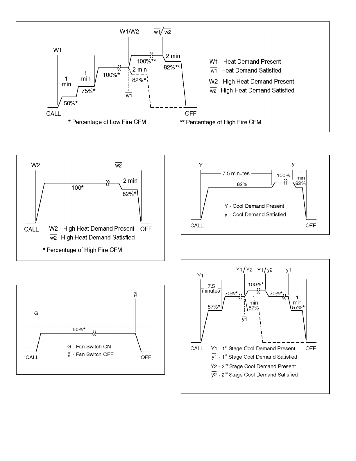
Figure 35. Indoor Blower Operation - 1st Stage-2nd Stage (W1/W2) Heat Call
Figure 36. Indoor Blower Operation - High Heat (W2)
Call
Figure 38. Indoor Blower Operation - Single Stage
Cooling
* Percentage of High Stage Cooling
Figure 37. Indoor Blower Operation - Call for Fan
* Percentage of High Stage Cooling
Figure 39. Indoor Blower Operation - Two Stage
Cooling
507335-02Page 34 of 39 Issue 2128
Page 35
Maintenance
WARNING
ELECTRICAL SHOCK, FIRE, OR EXPLOSION
HAZARD
Failure to follow the safety warnings exactly could
result in dangerous operation, serious injury, death, or
property damage.
Improper servicing could result in dangerous operation,
serious injury, death, or property damage.
• Before servicing, disconnect all electrical power to
furnace.
• When servicing controls, label all wires prior to
disconnecting. Reconnect wires correctly.
• Verify proper operation after servicing.
At the beginning of each heating season, a qualied
technician should check the system as follows:
Filters
All lters are installed external to the unit. Filters should
be inspected monthly. Clean or replace the lters when
necessary to ensure that the furnace operates properly.
Replacement lters must be rated for high velocity airow.
Table 1 lists recommended lter sizes.
Flue and Chimney
1. Check ue pipe, chimney and all connections for
tightness and to make sure there is no blockage.
2. Check unit for proper draft.
Electrical
1. Check all wiring for loose connections.
2. Check for the correct voltage at the furnace (furnace
operating). Correct voltage is 120VAC ± 10%.
3. Check amp draw on the blower motor with inner blower
panel in place.
Unit Nameplate____________ Actual_____________
Blower
Check the blower wheel for debris and clean if necessary.
The blower motors are pre-lubricated for extended bearing
life. No further lubrication is needed.
WARNING
The blower access panel must be securely in place
when the blower and burners are operating. Gas fumes,
which could contain carbon monoxide, can be drawn
into living space resulting in personal injury or death.
507335-02 Page 35 of 39Issue 2128
Page 36
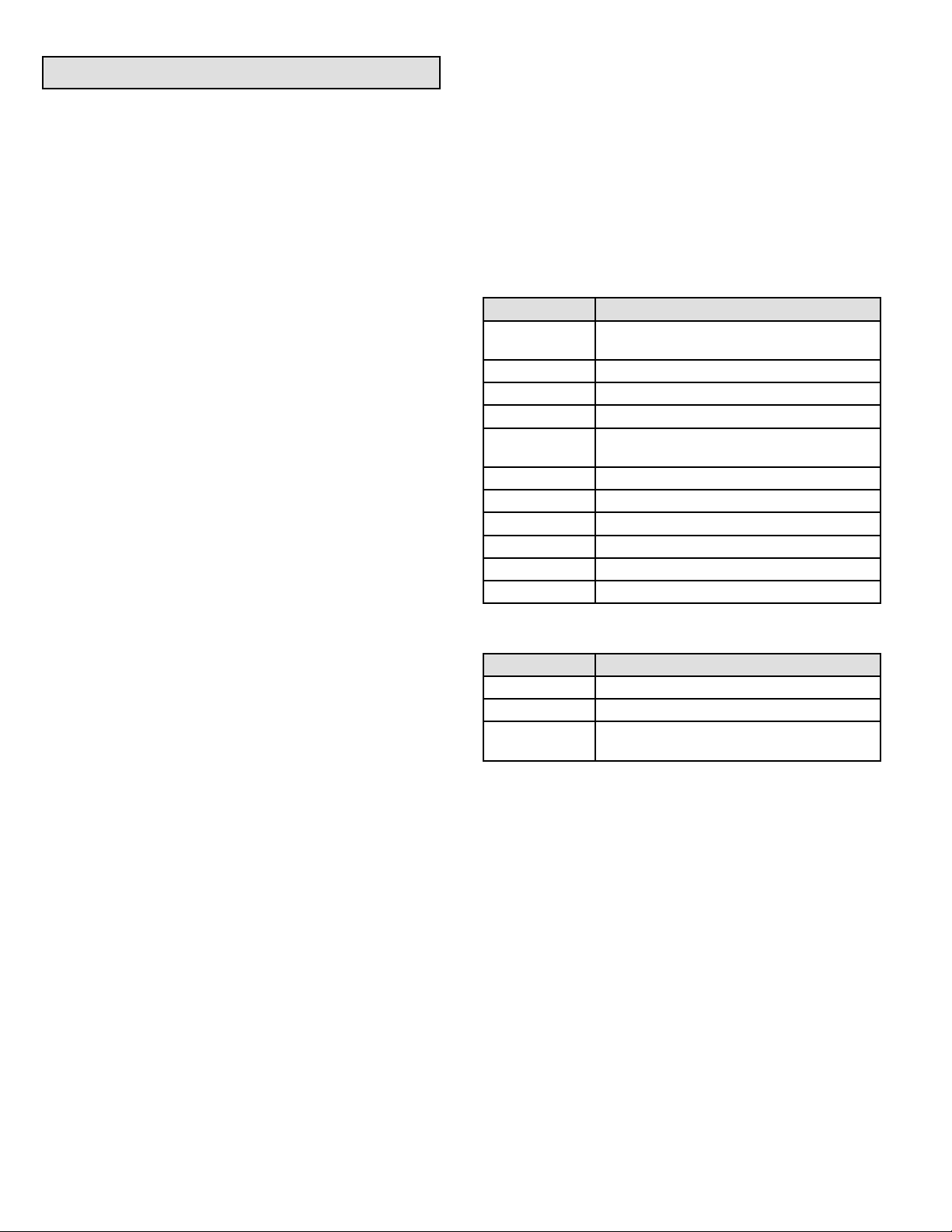
Control Diagnostics
Troubleshooting
Make the following visual checks before troubleshooting:
1. Check to see that the power to the furnace and the
integrated ignition/blower control board is ON.
2. The manual shutoff valves in the gas line to the furnace
must be open.
3. Make sure all wiring connections are secure.
4. Review the Sequence of Operation.
Start the system by setting thermostat above room
temperature. Observe system response. Then use the
information provided in this section to check the system
operation.
The furnace has a built-in, self-diagnostic capability. If a
system problem occurs, a fault code is shown by a red LED
on the control board. The control continuously monitors its
own operation and the operation of the system. If a failure
occurs, the LED will indicate the failure code. The ash
codes are presented in Table 17.
Fault Code History Button
The control stores the last ve fault codes in memory. A
pushbutton switch is located on the control (see Figure 43).
When the pushbutton switch is pressed and released, the
control ashes the stored fault codes. The most recent fault
code is ashed rst; the oldest fault code is ashed last. To
clear the fault code history, press and hold the pushbutton
switch in for more than 5 seconds before releasing.
High Heat State LED
On 80G2UH-V models, a green LED is provided on the
control board to indicate high heat state (see Table 18).
CFM LED
On 80G2UH-V models equipped with a variable speed
motor, an amber LED is provided on the control board to
display CFM. To determine what CFM the motor is delivering
at any time, count the number of times the amber LED
ashes. Each ash signies 100 CFM; count the ashes
and multiply by 100 to determine the actual CFM delivered
(for example: 10 ashes x 100 = 1000 CFM).
LED Status Fault Description
LED Off
LED On Normal operation
1 Flash Flame present with gas valve off
2 Flashes Pressure switch closed with inducer off
3 Flashes
4 Flashes High limit switch open
5 Flashes Not used
6 Flashes Pressure switch cycle lockout
7 Flashes Lockout due to no ignition
8 Flashes Lockout due to too many ame dropouts
9 Flashes Incorrect polarity and phasing
LED Status Fault Description
LED Off No demand for high heat
LED On High heat demand, operating normally
LED Flashing
No power to control or control hardware
fault detected
Low-re pressure, rollout, or aux limit switch
open
Table 17. Failure Codes - Red LED
High heat demand, high pressure switch
not closed
Table 18. High Heat State - Green LED
507335-02Page 36 of 39 Issue 2128
Page 37
Planned Service
The following items should be checked during an annual inspection. Power to the unit must be shut off for the service
technician’s safety.
Fresh air grilles and louvers (on the unit and in the
room where the furnace is installed) - Must be open and
unobstructed to provide combustion air.
Burners - Must be inspected for rust, dirt, or signs of water.
Vent pipe - Must be inspected for signs of water, damaged
or sagging pipe, or disconnected joints.
Unit appearance - Must be inspected for rust, dirt, signs of
water, burnt or damaged wires, or components.
Blower access panel - Must be properly in place and
provide a seal between the return air and the room where
the furnace is installed.
Return air duct - Must be properly attached and provide
an air seal to the unit.
Repair Parts List
Operating performance - Unit must be observed during
operation to monitor proper performance of the unit and
the vent system.
Combustion gases - Flue products must be analyzed and
compared to the unit specications.
Problems detected during the inspection may make it
necessary to temporarily shut down the furnace until the
items can be repaired or replaced.
Instruct the homeowners to pay attention to their
furnace. Situations can arise between annual furnace
inspections that may result in unsafe operation. For
instance, items innocently stored next to the furnace may
obstruct the combustion air supply. This could cause
incomplete combustion and the production of carbon
monoxide gas.
The following repair parts are available from the local distributor. When ordering parts, include the complete furnace model
number and serial number which are printed on the rating plate located on the furnace. All service must be performed by a
licensed professional installer (or equivalent), service agency, or gas supplier.
Cabinet Parts
• Heating compartment access panel
• Blower access panel
• Top cap
Control Panel Parts
• Transformer
• Two-stage, variable speed integrated control
• Door interlock switch
Blower Parts
• Blower wheel
• Blower housing
• Motor
• Motor electronics
• Power Choke (1 hp only)
• Motor mounting frame
• Blower housing cutoff plate
Heat Parts
• Flame sensor
• Heat exchanger assembly
• Gas Manifold
• Two speed combustion air inducer
• Two stage gas valve
• Main burner cluster
• Main burner orices
• Pressure switch
• Ignitor
• Primary limit control
• Flame rollout switch
• Secondary limit
507335-02 Page 37 of 39Issue 2128
Page 38
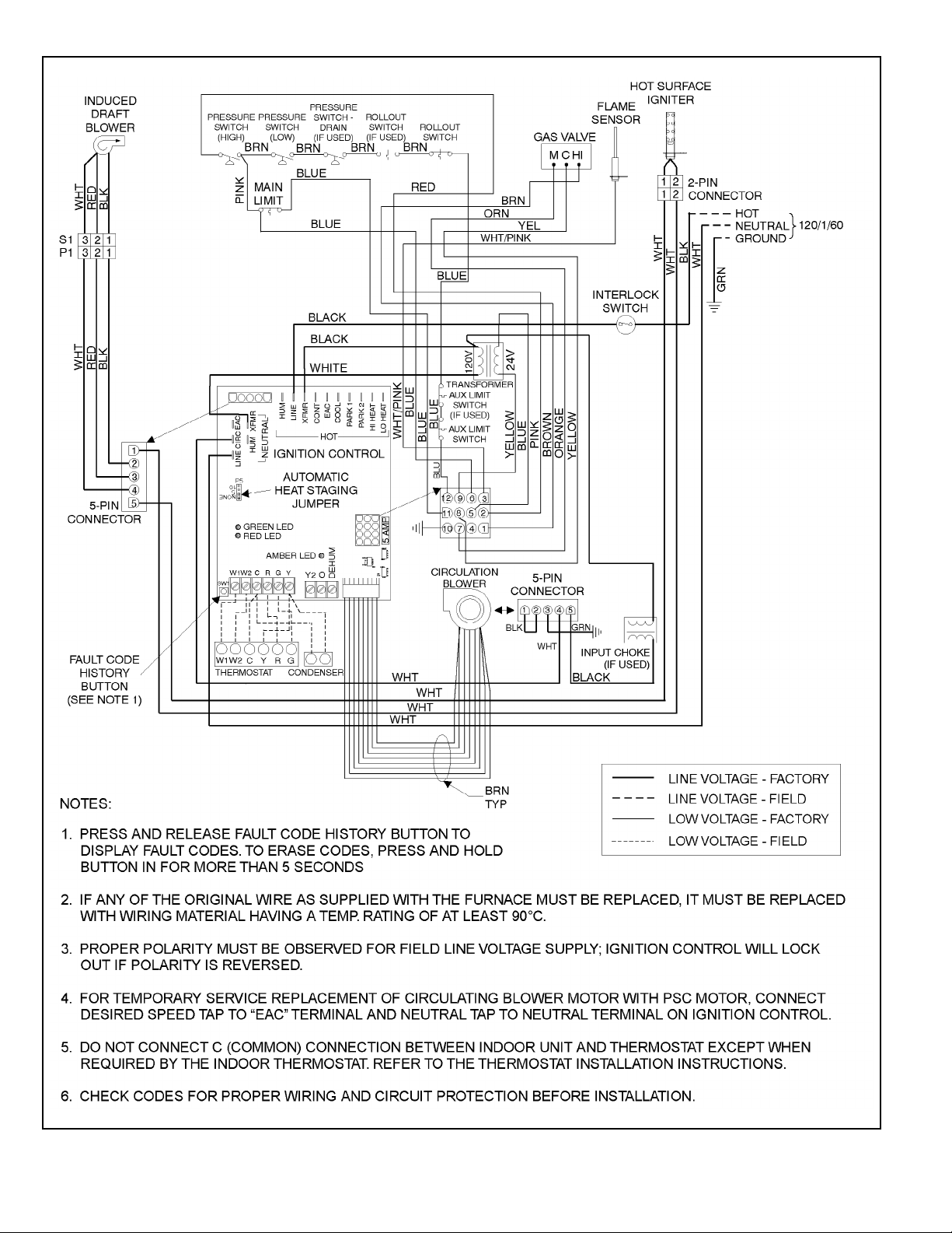
Figure 43. Typical Field Wiring Diagram
507335-02Page 38 of 39 Issue 2128
Page 39
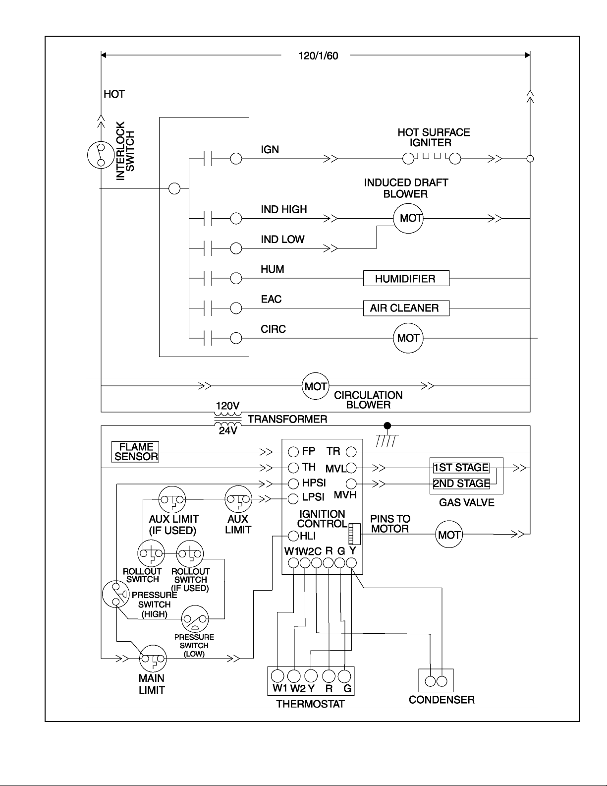
Figure 44. Wiring Schematic
507335-02 Page 39 of 39Issue 2128
 Loading...