

Page 1
2HP13/14 & 4HP13 SPLIT SYSTEM HEAT PUMP
INSTALLATION / START-UP INSTRUCTIONS
/HOMEOWNERS INFORMATION MANUAL
These instructions must be read and understood completely before attempting installation.
TABLE OF CONTENTS
Safety Precautions ..................................... 2
Unit Location & Installation ............................... 2
Rooftop Installation & Recommendations . . . . . . . . . . . . . . . . . . . . 3
Indoor Coil Piston Selection .............................. 3
Refrigeration Line Sets .................................. 3
Installation of Line Sets .................................. 4
Leak Check ........................................... 4
Evacuating & Charging .................................. 4
Opening Service Valve .................................. 5
Electrical Connections................................... 5
Control Wiring ......................................... 5
Start-Up Procedure ..................................... 6
Adjusting charge ....................................... 6
Defrost System ........................................ 7
Single Phase Wiring Diagram ............................. 9
3 Phase Wiring Diagram ................................. 10
Homeowner's Information ................................ 11
These units are designed for use in residential and light commercial type buildings. Heat Pumps may only be
installed with indoor combinations listed in the Air-Conditioning and Refrigeration Institute (ARI) Directory of
Certified Products.
Inspect the unit for any damage before installation. If damage is found, notify the transportation company
immediately and file a concealed damage claim.
Installation or repairs made by unqualified persons can result in hazards to you and others. Installation
MUST conform with local building codes and with the National Electrical Code NFPA 70/ANSI C1-1993 or
current edition and Canadian Electrical Code Part 1 CSA C22.1.
Improper installation, adjustment, alteration, service or maintenance will void the warranty. The qualified installer or
agency must use factory-authorized kits or accessories when added to this products. Refer to the individual instructions
included with the specific accessory kit.
NOTE
These instructions are intended as a general guide and do not supersede national, state or local codes in any way.
These instructions must be left with the property owner.
506162-02 Issue 0847 Page 1 of 14
Page 2
NOTE TO INSTALLING DEALER
These instructions and warranty are to be given
to the owner or prominently displayed near the
indoor air handler unit.
UNIT LOCATION & INSTALLATION
NOTE: In some cases noise in the living area has been
traced to gas pulsations from improper installation
of equipment.
1. Locate unit away form windows, patios, decks, etc.
where unit operation sounds may disturb customer.
This product and/or the indoor unit that is matched
with may contain fiberglass wool.
Disturbing the insulation during installation,
maintenance, or repair will expose you to fiberglass
wool dust. (Fiberglass wool is known to the State of
California to cause cancer.)
Fiberglass wool may also cause respiratory, skin,
and eye irritation.
To reduce exposure to this substance or for further
inform ation, consult material safety data sheets
available from your distributor.
Before installing, modifying, or servicing system,
main electrical disconnect switch must be in the OFF
position. There may be more than 1 disconnect
switch. Lock out and tag switch with a suitable
warning label. Electrical shock can cause personal
injury or death.
2. Ensure that vapor and liquid tube diameters are
appropriate to capacity of unit.
3. Run refrigerant tubes as directly as possible by
avoiding unnecessary turns and bends.
4. Leave some slack between structure and unit to
absorb vibration.
5. When passing refrigerant tubes through the wall, seal
opening with RTV or other silicon-based caulk.
6. Avoid direct tubing contact with water pipes, duct work,
floor joists, wall studs, floors, walls, and any structure.
7. Do not suspend refrigerant tubing from joists and studs
with a rigid wire or strap which comes in direct contact
with tubing.
8. Ensure that tubing insulation is pliable and completely
surrounds vapor tube.
When outdoor unit is connected to factory-approved
indoor unit, outdoor unit contains system refrigerant charge
for operation with indoor unit of the same size when
connected by 15 ft. of field-supplied tubing. For proper unit
operation, check refrigerant charge using charging
information located on control box cover.
IMPORTANT: Maximum liquid-line size is 3/8 in. O.D. for
all residential applications including long
Safety Precautions
Follow all safety codes. Wear safety glasses and work
gloves. Use quenching cloth for brazing operations. Have
fire extinguisher available. Read these instructions
thoroughly and follow all warning or cautions attached to
the unit.
1. Always wear proper personal protection equipment.
2. Always disconnect electrical power before removing
panel or servicing equipment.
3. Keep hands and clothing away from moving parts.
4. Handle refrigerant with caution, refer to proper MSDS
from refrigerant supplier.
5. Use care when lifting, avoid contact with sharp edges.
506162-02 Issue 0847 Page 2 of 14
Outdoor Section
Zoning ordinances may govern the minimum distance
the condensing unit can be installed from the property line.
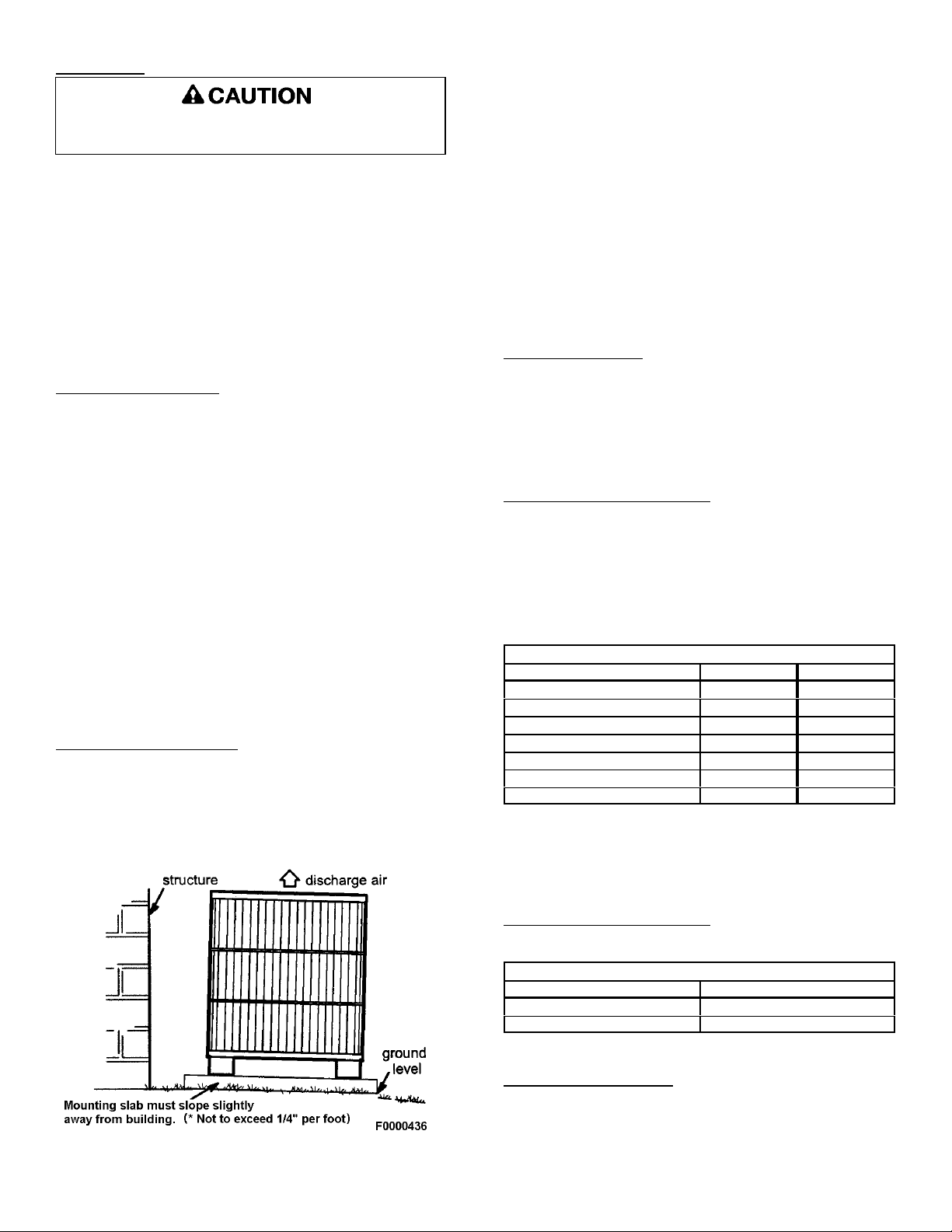
Install on a Solid, Level Mounting Pad
The outdoor section is to be installed on a solid
foundation. This foundation should extend a minimum of
2" (inches) beyond the sides of the outdoor section. To
reduce the possibility of noise transmission, the foundation
slab should NOT be in contact with or be an integral part of
the building foundation.
lines.
Page 3
Elevate Unit
Accumulation of water and ice in base pan may
cause equipment damage.
DO LOCATE THE UNIT:
! W ith proper clearances on sides and top of unit
! On a solid, level foundation or pad
! To minimize refrigerant line lengths
Elevate unit per local climate and code requirem ents to
provide clearance above estim ated snowfall level and
ensure adequate drainage of unit. Use snow stand in
areas where prolonged freezing temperatures are
encountered.
If conditions or local codes require the unit be attached
to pad or mounting frame, tie down bolts should be used
and fastened through knockouts provided in unit base pan.
Roof Top Installations
Mount on level platform or frame 6 inches above roof
surface. Place unit above a load-bearing wall and isolate
unit and tubing set from structure. Arrange supporting
members to adequately support unit and m inimize
transmission of vibration to building. Ensure roof structure
and anchoring method is adequate for location. Consult
local codes governing rooftop applications.
Roof mounted units exposed to winds above 5 mph
may require wind baffles to achieve adequate defrost. A
sheet metal baffle should be spaced 6-1/2" from the fall of
the coil. The height should cover the face of the coil and
the length should be 6" from the access panel.
NOTE: Unit must be level to within ± 2/ (± 3/8 in./ft) per
compressor manufacturer specifications.
Clearance Requirements
When installing, allow sufficient space for airflow
clearance, wiring, refrigerant piping, and service. For
proper airflow, quiet operation and maxim um efficiency.
Position so water, snow, or ice from roof or eaves cannot
fall directly on unit.
DO NOT LOCATE THE UNIT:
! On brick, concrete blocks or unstable surfaces
! Near clothes dryer exhaust vents
! Near sleeping area or near windows
! Under eaves where water, snow or ice can fall
directly on the unit
! w ith clearance less than 2 ft. from a second unit
! w ith clearance less than 4 ft. on top of unit
Operating Ambient
The minimum outdoor operating ambient in cooling
mode is 55/F, and the maximum outdoor operating
ambient in cooling mode is 125/F. The maximum outdoor
operating ambient in heating mode is 66/F.
Indoor Coil Piston Selection
The outdoor heat pump section must be matched to a
factory approved indoor section. It is mandatory that the
installer ensure that the correct piston is installed in the
indoor section. If necessary remove the existing piston and
replace it with the correct piston See indoor unit
instructions for details of changing the piston. Contact
your distributor for accessory piston kits.
Indoor (Cooling) Piston Size
13 SEER Heat Pump Indoor Piston Sizes
Unit Size 2HP13 4HP13
18 .055 .051
24 .063 .055
30 .068 .059
36 .076 .070
42 .076 .070
48 .082 .082
60 .098 .082
The evaporator coil may use an expansion valve (TXV) in place of piston.
NOTE: If a TXV is installed a hard start kit is required on
all models with reciprocating compressors. See spec
sheet for proper kit selection.
14 SEER Heat Pum p Models
All 14 SEER heat pump models are only rated with TXV on
the indoor side.
14 SEER Heat Pump Indoor TXV
Unit Size TX V Kit
18 thru 36 TXV3
42 thru 48 TXV5
Refrigeration Line Sets
Use only refrigerant grade copper tubes. Split
systems may be installed with up to 50 feet of line set (no
more than 20 feet vertical) without special consideration
(see long line set guidelines).
506162-02 Issue 0847 Page 3 of 14
Page 4
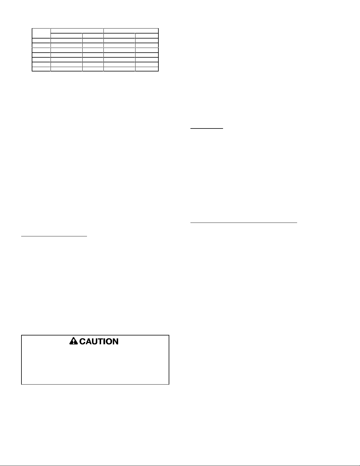
Recommended Liquid & Vapor Tube Diameters (In.)
Unit
Size
Connection Dia. Tube Dia. Connection Dia. Tube Dia.
018 3/8" 3 /8" 3/4 3/4
024 3/8" 3 /8" 3/4 3/4
030 3/8" 3 /8" 3/4 3/4
036 3/8" 3 /8" 3 /4 3/4
042 3/8" 3 /8" 7/8 7/8
048 3/8" 3 /8" 7/8 7/8
060 3/8" 3 /8" 7/8 *1-1/8
*FIELD SUPPLIED 7/8 X 1-1/8 CONNECTOR REQUIRED ON BOTH
ENDS OF VAPOR TUBING.
LIQUID VAPOR
It is important that no tubing be cut or seals broken
until you are ready to actually make connections to the
evaporator and to the condenser section. DO NOT remove
rubber plugs or copper caps from the tube ends until ready
to make connections at evaporator and condenser. Under
no circumstances leave the lines open to the atmosphere
for any period of time, if so unit requires additional
evacuation to remove moisture.
Be extra careful with sharp bends. Tubing can "kink"
very easily, and if this occurs, the entire tube length will
have to be replaced. Extra care at this time will eliminate
future service problems.
It is recommended that vertical suction risers not be
up-sized. Proper oil return to the compressor should be
maintained with suction gas velocity.
The following is the recommended method for making
braze connections at the refrigerant line connections:
1. Debur and clean refrigerant tube end with emery
cloth or steel brush.
2. Insert tubing into swage fitting connection.
3. W rap wet rags over valves to protect from heat.
4. Allow dry nitrogen to flow through refrigerant lines.
5. Braze joint, using a suitable brazing alloy for copper
to copper joints.
6. Quench the joint and tubing with water using a wet
rag. Leave rag on fitting body and re-wet with water
to help cool area.
Leak Check
Refrigeration lines and indoor coil must be checked for
leaks after brazing and before evacuation. The
recommended procedure is to apply a trace amount of
vapor refrigerant (approximately two ounces or 3 psig) into
the line set and indoor coil, then pressurize with 150 psig
of dry nitrogen. Use a refrigerant leak detector to check all
joints. The system may also be checked for leaks using a
halide torch or pressure and soapy solution. After
completion of leak check, relieve all pressure from system
before evacuation.
Installation of Line Sets
DO NOT fasten liquid or suction lines in direct contact
with the floor or ceiling joist. Use an insulated or
suspension type of hanger. Keep both lines separate, and
always insulate the suction line. Long liquid line runs (30
feet or more) in an attic will require insulation. Route
refrigeration line sets to minimize length.
DO NOT let refrigerant lines come in direct contact with
foundation. When running refrigerant lines through the
foundation or wall, openings should allow for a sound and
vibration absorbing material to be placed or installed
between tubing and foundation. Any gap between
foundation or wall and refrigerant lines should be filled with
a vibration damping m aterial.
If ANY refrigerant tubing is buried, provide a 6 inch
vertical rise at service valve. Refrigerant tubing
lengths up to 36 inches may be buried without further
special consideration. For lengths above 36 inches,
consult your local distributor.
Before making braze connections, be sure all joints are
clean. Before heat is applied for brazing, dry nitrogen
should be flowing through the tubing to prevent oxidation
and scale formation on the inside of the tubing.
Evacuating And Charging Instructions
NOTE: Intentional release of CFC or HCFC refrigerant
to the atmosphere violates Federal Law. It may
also violate State and Local Codes. Check all
Federal, State and Local Codes before
proceeding.
These outdoor units are pre-charged at the factory with
adequate refrigerant to handle 15 feet of refrigerant tubing.
NOTE: DO NOT use any portion of the charge for purging
or leak testing. It is mandatory that a thorough
evacuation of the refrigeration lines and indoor coil
be performed.
The liquid line and suction line service valves have been
closed after final testing at the factory. DO NOT disturb
these valves until the lines have been leak checked and
evacuated or the charge in the unit may be lost.
1. Connect the vacuum pump to the center hose of the
manifold gauge set, the low-pressure m anifold
gauge to the vapor service valve and the high
pressure manifold gauge to the liquid service valve.
NOTE: Unnecessary switching of hoses can be avoided
and complete evacuation of all lines can be
achieved by also connecting a branch hose from
the manifold gauge center port to a cylinder of the
proper refrigerant. Provide a separate shut-off
valve to vacuum pump to avoid contaminating
vacuum pump oil with refrigerant.
506162-02 Issue 0847 Page 4 of 14
Page 5
2. The valves should be kept in the "front seated"
(closed) position. This will allow evacuation of the
refrigeration lines and the indoor coil, without
disturbing the factory charge in the outdoor unit.
3. Follow the vacuum pump manufacturer's
instructions. Allow the pump to operate until the
system has been evacuated down to 300 microns.
Allow the pump to continue running for an additional
15 minutes. Turn OFF the pump and leave the
connections secured to the two (2) service valves.
After 5 minutes, if the system fails to hold 500
microns or less, check all connections for tight fit and
repeat the evacuation procedure.
4. Isolate the vacuum pump from the system by closing
the shutoff valves on the gauge-set. Disconnect the
vacuum pump.
Opening Service Valves
After evacuation of the connecting lines, remove the
service valve cap and fully insert the hex wrench into the
stem . A back-up wrench is required on the valve body to
open the valve stem. Back-out counterclockwise until the
valve stem just touches the coined edge.
Wrench sizes:
3/8 service valve: 3/16" Hex wrench
3/4 service valve: 5/16" Hex wrench
7/8 service valve: 5/16" Hex wrench
Replace service valve cap and torque to 8-11 ft-lb on 3/8"
valves; 12-15 ft-lb on 3/4" valves; 15-20 ft-lb on 7/8" valves.
Use backup wrench on valve body when torqueing valve
cap.
Provide line voltage power supply to unit from a properly
sized disconnect switch. Route power and ground wires
from disconnect switch to unit. Line voltage connections
are made at the line side of the contactor in the control box
of the outdoor unit. Follow the appropriate wiring diagram
attached to inside of the access panel.
Proper circuit protection recomm endations are indicated
on Unit Rating Plate. Time delay fuses are required to
prevent blowing due to starting current (the current in rush
when equipment starts is referred to as the Locked Rotor
Amps or (LRA). A fuse of this kind properly sized will give
maximum equipment protection.
Use copper wire only between disconnect switch and
unit.
Remove access panel to gain access to unit wiring.
Extend wires from disconnect through power wiring hole
provided and into unit control box. Flexible conduit is
required for the swing out control box feature.
The unit cabinet must have an uninterrupted or
unbroken ground to minimize personal injury if an
electrical fault should occur. The ground may consist
of electrical wire or metal conduit when installed in
accordance with existing electrical codes. Failure to
follow this warning can result in an electric shock,
fire, or death.
Connect ground wire to ground connection in control box
for safety. Connect power wiring to contactor.
Install Electrical Accessories
Refer to the instructions packaged with the accessories.
Electrical Connections
....
ELECTRICAL SHOCK HAZARD!
Turn OFF electric power before connecting unit,
performing any maintenance or removing
panels or doors. More than one disconnect
may be required to turn off all power.
FAILURE TO DO SO COULD RESULT IN BODILY
INJURY OR DEATH.
Be sure to check all local codes to determine that the unit
is installed accordance with local requirements. Consult
the National Electric Code for wire size requirements. Use
60/ C wire or higher. Always provide ground connections
to the outdoor unit. Power supply m ust agree with rating
on unit nameplate.
High voltage power connections to 3-phase m odels is
made to "Pig Tail" leads with field supplied splice
connectors.
Control Wiring
The control voltage is 24 Vac. NEC Class I insulated 18
AWG is required for control wiring. For lengths longer than
150 feet, contact your local distributor for technical service.
Ensure the room thermostat is properly installed per
instructions shipped with room thermostat. Generally the
thermostat should not be exposed to sunlight, drafts or
vibration and should not be mounted on exterior walls.
Low voltage control wire connections should be made to
the screw connection terminal board mounted on the
defrost control as shown. All low voltage control wiring
must be separated from incoming power leads.
506162-02 Issue 0847 Page 5 of 14
Page 6
Heat Pump Application with Electric Heat
Emergency Heat (heating heat pump)
If selector switch on thermostat is set to the emergency
heat position, the heat pump will be locked out of the
heating circuit, and all heating will be electric heat ( if
applicable). A jumper should be placed between W and E
on the thermostat so that the electric heat control will
transfer to the first stage heat on the therm ostat. This will
allow the indoor blower to cycle on and off w ith the electric
heat when the fan switch is in the AUTO position.
* Add Jumper on Subbase (O ptional)
Adjusting Charge
Factory charge is shown on the rating label located on
the access panel.
All split system heat pumps are factory charged for
15 feet of connecting line set and matched indoor fan
coil. Nameplate refrigerant charge should initially be
adjusted for line set lengths other than 15 feet. For line
sets shorter than 15 feet in length, remove charge. For line
sets longer than 15 feet, add charge. Oil charge is
sufficient for all line lengths.
Refrigeration Charge Adjustment
Liquid Line Diameter Oz. Per Linear Foot *
3/8" .6
* Factory charge for series is for 15' (ft.) line sets and matched fan
coil.
Before final adjustment is made to the refrigerant charge,
it is imperative that proper indoor airflow be established.
Airflow will be higher across a dry coil versus a wet coil.
Blower charts are calculated with a dry or wet coil basis.
Recomm ended airflow is 350-450 CFM per ton (12,000
Btuh) through a wet coil. Refer to indoor unit instructions
for methods of determining air flow and blower
performance.
Cooling Cycle Charge Adjustment
The optimum method for checking the charge is by
weight. However the following methods may be used
to confirm the proper charge:
Units with Indoor Pistons
Units installed with indoor pistons require charging with
the superheat method.
Start-Up Procedure
1. Check to ensure:
! Service valve and gage port caps are installed and
tightened.
! Voltage supply at unit agrees with nameplate
rating.
! Field wiring connections are tight and factory
wiring has not been disturbed and are tight.
! Indoor fan motor is on correct speed tap.
2. Set thermostat selector switch to OFF and fan control
switch to "Auto" is so equipped.
3. Close electrical disconnects to energize system.
4. Set room thermostat at desired temperature. Be sure
set point is below indoor ambient temperature.
5. Set the system switch of the thermostat on COOL (or
HEAT if applicable) and fan switch for continuous
operation (ON) or AUTO, as desired. There will be a
5 minute short cycle compressor delay on startup.
Operate unit for 15-20 minutes, then check the system
refrigerant charge.
6. Adjust refrigerant charge per "Adjusting Charge"
section.
The following procedure is valid when indoor airflow is
within ± 20% of its rated CFM.
1. Operate unit a minimum of 10 minutes before
checking charge.
2. Measure suction pressure by attaching a gage to
suction valve service port. Do not use compressor
suction port. Determine saturation temp from T/P
chart.
3. Measure suction temperature by attaching an
accurate thermistor type or electronic thermometer
to suction line at service valve.
4. Calculate superheat (measured temp. — saturation
temp.).
5. Measure outdoor air dry-bulb temperature with
thermom eter.
6. Measure indoor air (entering indoor coil) wet-bulb
temperature with a sling psychrometer.
7. Compare superheat reading at service valve with the
chart located on control box cover.
8. If unit has a higher suction line temperature than
charted temperature, add refrigerant until charted
temperature is reached.
9. If unit has a lower suction line temperature than
charted temperature, reclaim refrigerant until charted
temperature is reached.
506162-02 Issue 0847 Page 6 of 14
Page 7
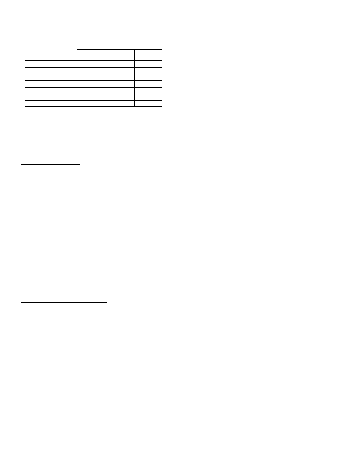
10. Remove charge if superheat is low and add charge
if superheat is high.
Required Subcooling
Model
18 14 10 12
24 9 3 14
30 13 8 17
36 9 14 10
42 11 3 16
48 8 9 7
60 12 - 13
2HP13 2HP14 4HP13
(± I/F)
NOTE: If a TX V is installed on indoor unit, a hard start kit
is required on all models with reciprocating compressors.
Refer to the specification sheet for details. Hard start kits
are also recommended for areas with utility power lower
than 208 Vac.
Units with Indoor TXV
Units installed with TXV on indoor side, require charging
with the subcooling method.
1. Operate unit a minimum of 10 minutes before
checking charge.
2. Measure liquid service valve pressure by attaching
an accurate gage to service port. Determine
saturation temp. from T/P chart.
3. Measure liquid line temperature by attaching an
accurate thermistor type or electronic thermometer
to liquid line near outdoor coil.
4. Calculate subcooling (saturation temp.— measured
temp.).
5. Find the point where required subcooling
temperature intersects measured liquid service valve
pressure.
6. Add refrigerant if subcooling is lower than table
below. Recover refrigerant if subcooling is high.
SYSTEM OPERATION
The outdoor unit and indoor blower cycle on demand
from the room thermostat. When the thermostat blower
switch is in the ON position, the indoor blower operates
continuously.
Filter Drier
The outdoor unit is equipped with a bi-flow filter drier. If
replacement is necessary, order new dryer according to the
service parts m anual.
Emergency Heat Function (Room Thermostat)
An emergency heat function is designed into some room
thermostats. This feature is applicable when isolation of
outdoor unit is required or when auxiliary electric heat is
staged by outdoor thermostats. When the room thermostat
is placed in the em ergency heat position, the outdoor unit
control circuit is isolated from power and field-provided
relays bypass the outdoor thermostats. An amber
indicating light simultaneously comes on to remind the
homeowner that he is operating in the emergency heat
mode.
Em ergency heat is usually used during an outdoor unit
shutdown, but it should also be used following a power
outage. If power has been off for over an hour and the
outdoor temperature is below 50/F (10/C). System should
be left in the em ergency heat mode at least six hours to
allow the crankcase heater sufficient tim e to prevent
com pressor slugging. This applies only to systems with
crank case heaters.
Defrost System
The defrost system includes two (2) components: a
defrost thermostat and a defrost control.
Defrost Thermostat
Heating Check Chart Procedure
To check system operation during heating cycle, refer to
the Heating Check Chart located on back of control box
cover. This chart indicates wheth er a correct relationship
exists between system operating pressure and air
temperature entering indoor and outdoor units. If pressure
and temperature do not match on chart, system refrigerant
charge may not be correct. Do not use chart to adjust
The defrost thermostat is located on the outdoor coil of
most models and on the liquid line between the
check/expansion valve and the distributor on R-4110A TXV
equipped models. When defrost thermostat senses 29/F
(42/ on R-410A TXV’s) or cooler, the therm ostat contacts
close and send a signal to the defrost control board to start
the defrost tim ing. It also terminates defrost when the
liquid line warms up to 60/F.
refrigerant charge.
Charge must be rechecked again during the cooling
season.
Defrost Control
The defrost control board includes the combined
functions of a time/temperature defrost control, defrost
relay, diagnostic LEDs and terminal strip for field wiring
Cold Weather Application
connections.
A cold weather accessory kit may be required for heat
pumps operating at ambient conditions below 25/ F.
Supplemental heat should be provided for these conditions
due to the expected performance degeneration.
The control provides automatic switching from normal
heating operation to defrost mode and back. During
compressor cycle, the control accumulates compressor
run times at 30-, 60-, or 90-minute field-adjustable
506162-02 Issue 0847 Page 7 of 14
Page 8
intervals. If the defrost thermostat is closed when the
selected compressor run tim e interval ends (call for
defrost), the defrost relay is energized and defrost begins.
The factory setting is 60 minutes. However, if frost
accumulation is easily cleared, the optimum efficiency
setting is 90 minutes.
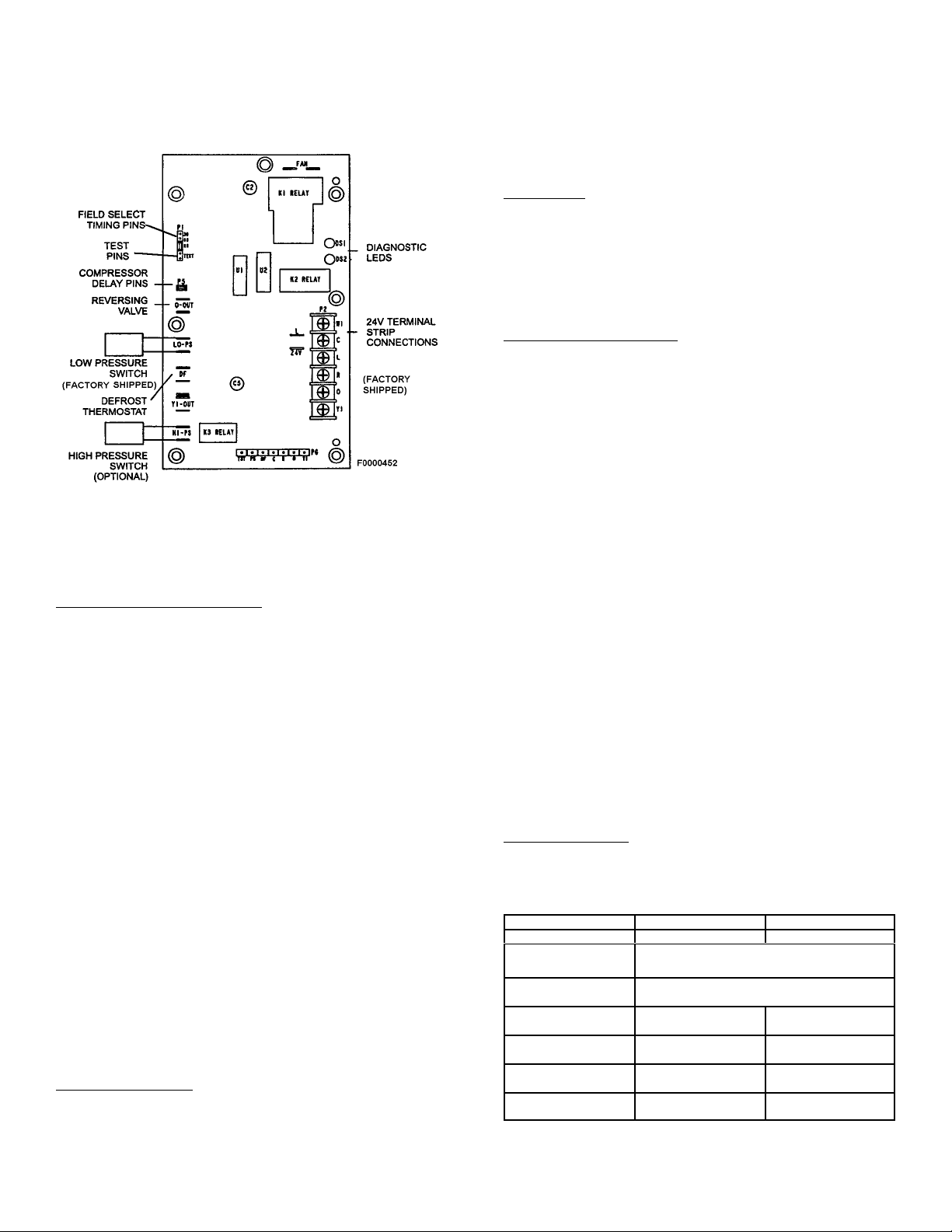
Outdoor Unit Defrost Control Board
Defrost Control Timing Pins
Each timing pin selection provides a different
accumulated compressor run time period for one defrost
cycle. This time period must occur before a defrost cycle
is initiated. The defrost interval can be adjusted to 30
(/T1), 60 (T2), or 90 (T3) minutes. The defrost tim ing
jumper is factory-installed to provided a 90-minute defrost
interval. If the timing selector jumper is not in place the
control defaults to a 90-minute defrost interval. The
maximum defrost period is 14 minutes and cannot be
adjusted.
defrost mode when the com pressor delay jumper is
removed.
NOTE: The 30 second "off" cycle is not functional when
jumpering the TEST pins.
Time Delay
The timed-off delay is 5 minutes long. The delay help to
protect the compressor from short-cycling in case the
power to the unit is interrupted or a pressure switch opens.
The delay is bypassed by placing the timer select jumper
across the TEST pins for 0.5 seconds.
Pressure Sw itch Circuit
The defrost control incorporates 2 pressure switch
circuits. The optional high pressure switch connects to the
boards HI PS terminals. The low pressure switch is factory
installed.
During a single demand cycle, the defrost control will lock
out the unit after the fifth time that the circuit is interrupted
by any pressure switch wired to the control board. In
addition, the diagnostic LEDs will indicate a locked-out
pressure switch after the fifth occurrence of an open
pressure switch. The unit will rem ain locked out until
power to the board is interrupted, then re-established or
until the jum per is applied to the TEST pins for 0.5
seconds.
NOTE: The defrost control board ignores input from the
low-pressure switch terminals as follows:
! During the TEST mode,
! During the defrost cycle,
! During the 90 second start-up period,
! and for the first 90 seconds each time the reversing
valve switches heat/cool modes. If the TEST pins
are jumpered and the 5 minute delay is being bypassed, the LO PS terminal signal is not ignored
during the 90 second start-up period.
A TEST option is provided for troubleshooting. The
TEST mode may be started any time the unit is in the
heating mode and the defrost thermostat is closed or
jumpered. If the jumper is in the TEST position at power-
Diagnostic LEDS
The defrost board uses 2 LEDs for diagnostics. The
LEDs flash a specific sequence according to the condition.
up, the control will ignore the test pins. When the jumper
is placed across the TEST pins for 2 seconds, the control
will enter the defrost mode. If the jumper is removed
before an additional 5 second period has elapsed ( 7
seconds total), the unit will remain in defrost mode until the
defrost thermostat opens or 14 minutes have passed. If
the jumper is not rem oved until after the additional 5
second period has elapsed, the defrost will terminate and
the test option will not function again until the jumper is
removed and re-applied.
Compressor Delay
The defrost board has a field-selectable function to
reduce occasional sounds that m ay occur while the unit is
Mode Green LED (DS2) Red LED (DS1)
No power to control OFF OFF
Normal operation/
power to control
Anti-short cycle
lockout
Low pressure switch
fault (Optional)
Low pressure switch
lockout (Optional)
High pressure switch
fault (Optional)
High pressure Switch
lockout (Optional)
Defrost Control board Diagnostic LED
Simultaneous Slow FLASH
Alternating Slow FLASH
OFF Slow FLASH
OFF ON
Slow FLASH OFF
ON OFF
cycling in and out of the defrost mode. The compressor
will be cycled "off" for 30 seconds going in and out of the
506162-02 Issue 0847 Page 8 of 14
Page 9
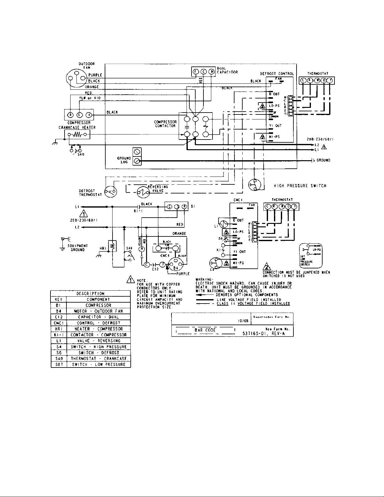
H/P SINGLE PHASE WIRING DIAGRAM
506162-02 Issue 0847 Page 9 of 14
Page 10
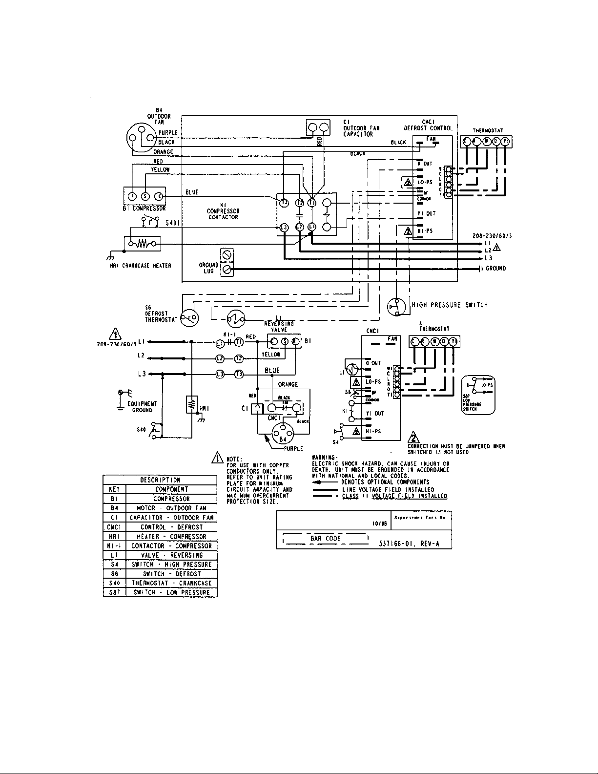
H/P 3 PHASE WIRING DIAGRAM
506162-02 Issue 0847 Page 10 of 14
Page 11
Homeowner's Information
ELECTRICAL SHOCK HAZARD!
Turn OFF electric power to unit before performing
any maintenance or removing panels or doors.
FAILURE TO DO SO COULD RESULT IN BODILY
INJURY OR DEATH.
Heat Pump Operation
Your new heat pump has several characteristics that you
should be aware of:
! Heat pumps satisfy heating demand by delivering
large amounts of warm air into the living space. This
is quite different from gas-or oil-fired furnaces or an
electric furnace which deliver lower volumes of
considerably hotter air to heat the space.
! Do Not be alarmed if you notice frost on the outdoor
coil in the winter months. Frost develops on the
outdoor coil during the heating cycle when
temperatures are below 45/F. An electronic control
activates a defrost cycle lasting 5 to 15 minutes at
preset intervals to clear the outdoor coil of the frost.
! During the defrost cycle, you may notice steam rising
from the outdoor unit. This is a normal occurrence.
The thermostat may engage auxiliary heat during the
defrost cycle to satisfy a heating dem and; however.,
the unit will run to normal operation at the conclusion
of the defrost cycle.
In case of extended power outage...
If the outdoor temperature is below 50/F and power to
your outdoor unit has been interrupted for 6 hours or
longer, observe the following when restoring power to your
heat pump system.
! Set the room thermostat selector to the "Emergency
Heat" setting to obtain temporary heat for a minimum
of 6 hours. This will allow system refrigerant
pressures and temperatures enough time to return
to a stabilized condition.
! In Emergency Heat mode, all heating dem and is
satisfied by auxiliary heat; heat pump operation is
locked out. After a 6 hour "warm-up" period, the
thermostat can then be switched to the "Heat" setting
and normal heat pump operation my resume.
! Heat pumps (in the cooling mode) rem ove humidity
from your home. Depending on the amount of
moisture in the air inside your home, water will trickle
from the condensate drain of the cooling coil.
Thermostat Operation
The wall-mounted therm ostat controls your air
conditioner. The thermostat is available in various
configurations from different manufacturers. The
information below is typical for most thermostats. Ask your
dealer for specific information regarding the model of
thermostat installed.
Temperature Setting Levers
Most heat pum p thermostats have 2 temperature
selector levers: one for heating and one for cooling. Set
the levers or dials to the desired temperature set points for
both heating and cooling. Avoid frequent temperature
adjustment; turning the unit off and back on before
pressures equalize puts stress on the unit compressor.
On heat pump systems, increasing your thermostat
setting by more than 2 degrees may cause supplem ental
heaters to turn on, reducing potential energy savings.
Fan Switch
In AUTO or INT (intermittent ) mode, the blower operates
only when the thermostat calls for heating or cooling. This
mode is generally preferred when humidity control is a
priority. The ON or CONT mode provides continuous
indoor blower operation, regardless of whether the
compressor or auxiliary heat are operating. This mode is
required when constant air circulation or filtering is desired.
System Switch
Set the system switch for heating, cooling or auto
operation. The auto mode allows the heat pump to
autom atically switch from heating mode to cooling m ode to
maintain predetermined comfort settings. Many heat pump
thermostats are also equipped with an emergency heat
mode which locks out heat pump operation and provides
temporary heat supplied by the auxiliary heat.
Indicating Light
Most heat pump thermostats have an amber light which
indicates when the heat pump is operating in the
emergency heat mode.
Temperature Indicator
The temperature indicator displays the actual room
temperature.
Fan Control
For fan control your thermostat may have a Fan
Selection Switch that allows you to run the fan continuously
or cycle it automatically with the heating or cooling system.
Switch the lever to ON for continuous operation and to
AUTO for automatic cycling.
For maximum comfort satisfaction and continual air
cleaning/filtering, constant fan operation is recommended.
506162-02 Issue 0847 Page 11 of 14
Page 12
On models without a fan Selection Switch, the fan will
cycle with the outdoor unit.
Periodically, debris should be brushed from the condenser
coils.
Important System Information
! Your system should never be operated without a
clean air filter properly installed.
! Return air and supply air registers should be free
from restrictions or obstructions to allow full flow of
air.
Regular Maintenance Requirements
Your system should be regularly inspected by a qualified
service technician. These regular visits may include
(among other things) checks for:
! Motor operation
! Ductwork air leaks
! Coil & drainpan cleanliness (indoor & outdoor)
! Electrical component operation & wiring check
! Proper refrigerant level & refrigerant leaks
! Proper airflow
! Drainage of condensate
! Air filter(s) performance
! Blower wheel alignment, balance & cleaning
! Primary & secondary drain line cleanliness
! Proper defrost operation (heat pumps)
There is some routine maintenance procedures you can
do to help keep your system operating at peak
performance between visits.
Air Filter
Inspect air filters at least monthly and replace or clean as
required. Disposable filters should be replaced. W ashable
filters may be cleaned by soaking in mild detergent and
rinsing with cold water. Replace filters with the arrows
pointing in the direction of airflow. Dirty filters are the most
common cause of poor heating / cooling performance and
compressor failures.
Indoor Coil
If the system has been operated with a clean filter in
place, it should require minim al cleaning. Use a vacuum
cleaner and soft brush attachment to remove any
accumulation of dust from the top and underside of the
finned coil surface. However, perform this maintenance
only when the coil is com pletely dry.
If the coil cannot be cleaned by this method, call your
dealer for service. It may need a detergent solution and
rinsing with water for cleaning, which may require coil
removal. You should not attempt this yourself.
Condensate Drain
During cooling season check at least monthly for free
flow of drainage and clean if necessary.
.....
SHARP OBJECT HAZARD!
Condenser coils have sharp edges. W ear adequate
body protection on body extremities (e.g. gloves).
FAILURE TO FOLLOW THIS WARNING COULD
RESULT IN BODILY INJURY.
Use a soft bristle brush with light pressure only. DO NOT
damage or bend condenser coil fins. Damaged or bent fins
may affect unit operation.
Painted Surfaces
For maximum protection of the unit's finish, a good grade
of automobile wax should be applied every year. In
geographical areas where water has a high concentration
of minerals (calcium , iron, sulfur, etc.). It is recommended
that lawn sprinklers not be allowed to spray the unit. In
such applications, the sprinklers should be directed away
from the unit. Failure to follow this precaution m ay result
in premature deterioration of the unit finish and metal
components.
In sea coast areas, special maintenance is required due
to the corrosive atmosphere provided by the high salt
concentration in ocean mists and the air. Periodic washing
of all exposed surfaces and coil will add additional life to
your unit. Please consult your installing dealer for proper
procedures in your geographic area.
IF YOUR SYSTEM DOES NOT WORK,
BEFORE REQUESTING A SERVICE CALL:
1. Ensure thermostat is set below (cooling) or above
(heating) room temperature and that the system lever
is in the "COOL", "HEAT" or "AUTO" position.
2. Inspect your return air filter: If it is dirty your air
conditioner may not function properly.
3. Check indoor and outdoor disconnect switches.
Confirm circuit breakers are ON or that fuses have not
blown. Reset breakers/replace fuses as necessary.
4. Inspect the outdoor unit for clogged condenser coils,
(grass cuttings, leaves, dirt, dust or lint). Ensure that
branches, twigs or other debris are not obstructing the
condenser fan.
IF YOUR SYSTEM STILL DOES NOT OPERATE,
CONTACT YOU SERVICING DEALER.
Be sure to describe the problem, and have the model
and serial numbers of the equipment available.
Condenser Coils
Grass cuttings, leaves, dirt, dust, lint from clothes dryers,
and fall off from trees can be drawn into coils by movement
of the air. Clogged condenser coils will lower the efficiency
of your unit and could cause dam age to the condenser.
506162-02 Issue 0847 Page 12 of 14
If warranted replacements parts are required, the
warranty must be processed through a qualified distribution
location.
Page 13
ALLIED AIR ENTERPRISES
EQUIPMENT LIMITED WARRANTY
APPLIES IN U.S.A. AND CANADA ONLY
FAILURE TO MAINTAIN YOUR EQUIPMENT WILL VOID THIS WARRANTY
COVERED EQUIPMENT
The following Allied Air Enterprises heating and cooling equipment is covered by the Limited Warranty:
Condensing Units: 2SCU13, 4SCU13, 4SCU14, 4SCU16, 4SCU18, 2AC13, 2AC14,4AC13
Heat Pumps: 2SHP13, 4SHP13, 2SHP14, 4SHP14, 4SHP16, 4SHP18, 2HP13, 2HP14, 4HP13
Gas Furnaces: G1N80, G1D80, G2D80, G1D91,G1D93, G2D93, G2D95, FPBB, CG80, CG90, CG93, CG90UA
Oil Furnaces: LBR80, LBF80, LHF80, LUF80, RULF, RLBR, RLBU, RLHF, RLHR
Electric Furnaces: EFC, EFV
Evaporator Coils: EC, EU, EH, EM
Air Handlers: BCS2, RBCS2
Package Equipment:: 2PCE13, 4PCE13, 4PCE15, 2PGE13, 4PGE13, 4PGE15, 2PHP13, 4PHP13, 4PHP15, 2SG13, 2SH13, 2SA13
PARTS and COMPRESSOR COVERAGE
The covered equipment and covered parts and compressor are warranted by Allied Air for a period of five (5) years from the date of the original installation, when installed in a residential application
(which includes homes, duplexes, apartments and condominiums). The covered equipment and covered parts and compressor are warranted by Allied Air for a period of one (1) year from the date
of the original installation, when installed in non-residential applications. If during this period, a covered component fails because of a manufacturing defect, Allied Air will provide a free replacement
part to the owner through a licensed service contractor utilizing an Allied Air distributor. You must pay shipping charges and all other costs of warranty service. Allied Air will not pay labor involved
in diagnostic calls or in removing, repairing, servicing or replacing parts. Such cost may be covered by a separate warranty provided by the installer.
HEAT EXCHANGER EXTENDED COVERAGE
All covered heat exchangers are warranted by Allied Air for a period of twenty (20) years from the date of original installation.
Heat Exchanger Availability: If a replacement heat exchanger is no longer available for a unit covered by this warranty, Allied Air will allow a credit toward the purchase of an equivalent Allied
Air furnace (at the current suggested distributor’s cost).
NOTE: If the date of original installation cannot be verified, the warranty period will be deemed to begin ninety (90) days after the date of manufacture.
EXCLUD ED COMPO NENTS
The following components are not covered by this warranty: cabinets, cabinet pieces, air filters, driers, refrigerant, refrigerant line sets, belts, wiring, fuses, oil nozzles, unit accessories and any parts
not affecting unit operation.
CARE OF EQUIPMENT
Your new Allied Air unit must be properly installed, operated and maintained in accordance with the unit installation, operation and maintenance instructions provided with each Allied Air unit. Failure
to provide maintenance per Allied Air instr uctions will void this warranty.
WARRANTY PROCEDURE
When service or warranty parts are required:
1. Call your local licensed service dealer or contractor
2. If the in stalli ng deal er is un able to provide warrant y service, check onlin e at www.al liedai r.com.
3. Be prepared to furnish the following information:
a. complete model and serial number
b. proof of required periodic maintenance, installation date and location
c. an accurate description of the problem
WARRANTY LIMITATIONS
1. This warranty is void if the covered equipment is removed from the original installation site.
2. This warranty do es not co ver damag e or defe ct resul ting fr om:
a. flood, wind, fire, lightning, mold, or installation and operation in a corrosive atmosphere, or otherwise in contact with corrosive material (chlorine, fluorine, salt, recycled waste water, urine,
fertilizers, or other damaging substances or chemicals); accident, or neglect or unreasonable use or operation of the equipment including operation of electrical equipment at voltages
other than the range specified on the unit nameplate (i ncludes damages caused by brownouts)
b. modification, change or alteration of the equipment, except as directed in writing by Allied Air
c. operation with system components (indoor unit. outdoor unit and refrigerant control devices) which are not an ARI match or meet the specifications recommended by Allied Air
d. operation of furnaces with return air temperatures of less than 60/ F (16/ C) or operation of a furnace field installed downstream from a cooling coil
e. use of contaminated or refrigerant not compatible with the unit
The installation of replacement parts under the terms of this warranty does not extend the original warranty period.
Allied Air makes no express warranties other than the warranty specified above. All implied warranties, including the implied warranties of merchantability and fitness for a particular
purpose, are excluded to the extent to a period legally permissible. Should such exclusion or limitation of the warranty be unenforceable, such implied warranties are in any event limited
to a period of one (1) year. Liabilit y for incidental and conseq uential damages is excl uded. Some states do not allow limitat ion of incidental damages, so the limitations or exclusions
may not apply to you. Allied Air will not pay electricity or fuel costs, or increases in electricity or fuel costs, for any reason whatsoever, including additional or unusual use of
supplemental electric heat. This warranty does not cover lodging expenses or labor charges.
Allied Air shall not be liable for any default or delay in performance under this warranty caused by any contingency beyond its control.
This warranty gives you specific legal rights, and you may also have other rights which vary from state to state.
NOTE TO CUSTOMER
Please complete information below and retain this warranty for your records and future reference.
Outside Unit Model Number: __________________________________________ Serial Number: ___________________________ Installed Date: ______________
Furnace / Air Handler: _______________________________________________ Serial Number: ___________________________ Installed Date: ______________
Indoor Coil Model N umber: ___________________________________________ Serial Number: ___________________________ Installed Date: ______________
Installing Company Name: _________________________________________________________________________ Phone: ______________________________
Installing Company Address: ___________________________________________ State / Province: ________________________ Zip / Postal Code: ___________
215 Metropolitan Drive, West Columbia, SC 29170
506162-02 Issue 0847 Page 13 of 14
Page 14

NOTES
506162-02 Issue 0847 Page 14 of 14
 Loading...