

Page 1
High-Capacity LED Industrial Emergency Lighting Unit
NEMA 4X, IP66, C1D2 & C2D1
Spectron & Spectron Remote Capacity Models
Installation, Operation, and Service Instructions
DYN Series
IMPORTANT SAFEGUARDS
When using electrical equipment, basic safety precautions should
always be followed including the following.
READ AND FOLLOW ALL SAFETY
INSTRUCTIONS
1. Do not let power supply cords touch hot surfaces.
2. Do not mount near gas or electric heaters.
3. Equipment should be mounted in locations and at heights where it will not readily be subject
to tampering by unauthorized personnel.
4. The use of accessory equipment not authorized by the manufacturer may cause an
unsafe condition.
5. Do not use this equipment for other than its intended purpose.
6. Servicing of this equipment should be performed by qualied service personnel.
7. Test cycling: the Life Safety Code (NFPA 101) requires testing of emergency lighting units once a month for a
minimum of 30 seconds, and once a year for a minimum of 90 minutes.
INSTALLER:
•SEE UNIT LABEL FOR ADDITIONAL MODEL SPECIFICATIONS
•SAVE THESE INSTRUCTIONS FOR USE BY OWNER/OCCUPANT
RECYCLING INFORMATION
All steel, aluminum and thermoplastic parts are recyclable.
NOTICE: Emergency units contain rechargeable batteries which
must be recycled or disposed of properly.
Hubbell Lighting, Inc. Life Safety Products • www.dual-lite.com
Copyright
©
Hubbell Lighting, Inc., All Rights Reserved • Specications subject to change without notice. • Printed in U.S.A.
93066456_A 10/3/15
Service / Maintenance
93049060
93049063
93055894
93055812
93055892
93055893
93055895
93055897
93055896
93061887
Maintenance
This emergency lighting unit should be tested and maintained in accordance with National Electrical Code and NFPA 101 Life Safety
Code requirements. It is recommended that emergency light xtures be tested for 30 seconds once a month and for 90 minutes once
a year.
Taking A Unit Out of Service
If a unit is to be deliberately taken out of service for an extended period, the battery lead connector should be disconnected from the
charger circuit board and insulated so that the battery will go into storage in a fully charged condition.
Replacing the Battery:
1. De-energize the AC power.
2. Remove the front housing cover.
3. Disengage the battery and heater (if provided) harness from the charger PCB harness.
4. Disconnect the battery strap and remove battery pack.
5. Replace with new battery (see unit model label or battery label for correct p/n)
and repeat steps above in reverse.
Replacing LED Lamps
The LED lamp heads are eld replaceable. Please see Dual-Lite.com for further assistance.
Troubleshooting
Emergency circuit does not work
• Batteries are shipped uncharged, please charge for 24 hours before testing.
• Make sure the switch pcb and the button/light pipe is correctly seated and aligned.
• Check wiring connections.
INSTALLATION
This Industrial Unit is designed to be mounted on a wall, ceiling or pole (optional). Provide standard units with a single unswitched
power supply from a 120 - 277VAC branch circuit used for normal lighting in the areas to be protected. For Spectron
self-testing/self diagnostic units, provide unit with a 120/277VAC branch circuit.
The DYN Industrial unit is equipped with intelligent wiring. Connect the black wire from unit to the building hot wire (120 or
277VAC) and the white wire to the building com wire. (Exceptions: All Non-Spectron models should be connected to 120, 240
or 277VAC supplies only.)
WARNING- This product contains chemicals known to the State of Califorina to cause cancer, birth defects, and/or other
reproductive harm. Thoroughly wash hands after installing, cleaning, or otherwire touching this product.
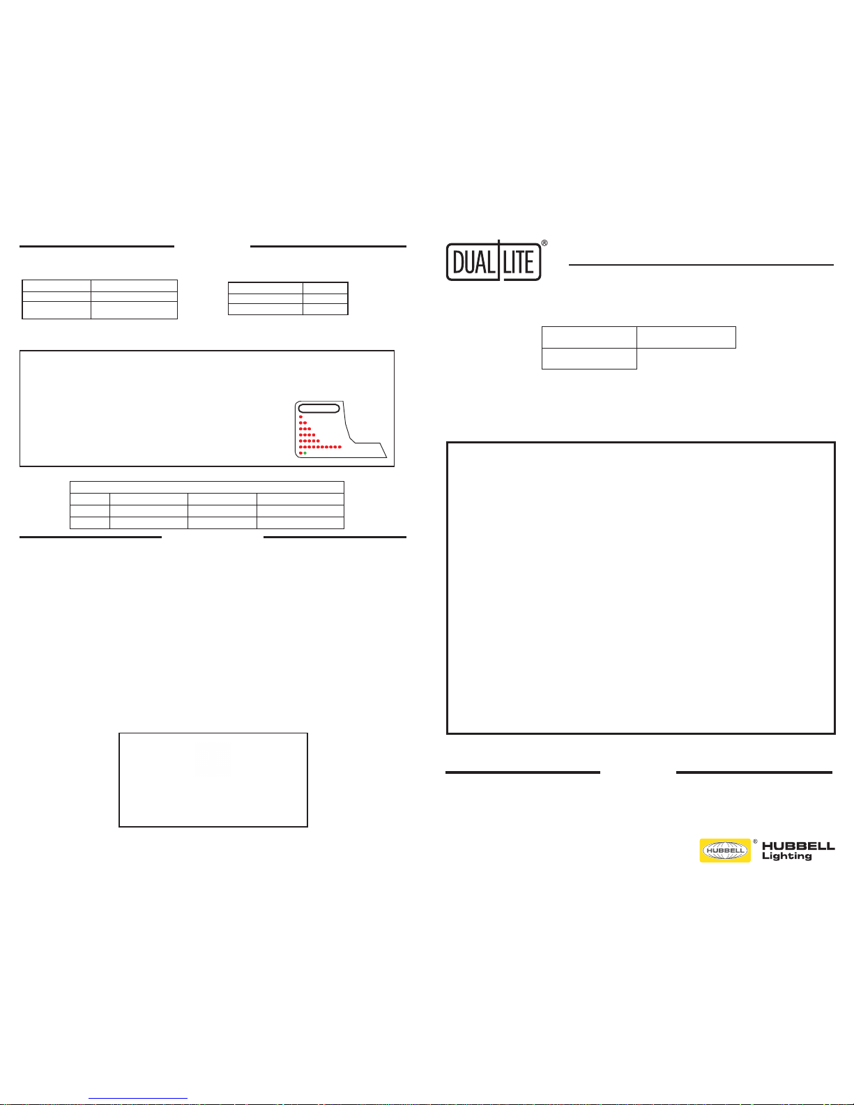
Initiating Action Test Cycle
Press test switch once 1 minute
Press test switch twice 90 minutes
Manual Tests
Using the unit test switch, users can initiate different
duration test cycles based on the following table:
Pressing the test switch any time after a 90 minute test
cycle has begun cancels the remainder of the 90 minute
test and returns the unit to normal operation.
Testing Period Duration of Test
Once a month 1 minute
Once every Alternating:
6 months 30 minutes or 60 minutes
Automatic Tests
The unit will automatically initiate a self-test/self-diagnostic
cycle based on the following table:
93052054
LED Status Indicator:
A green/red LED is provided on the control pane
of all models equipped with the Spectron option.
Green Operating Status LED:
The green Operating Status LED serves as both an AC power
and self-test indicator. During normal operation, the green
Operating Status LED will be illuminated, indicating the
presence of AC power. During all automatic or manual self-test
cycles, the green Operating Status LED will blink “twice” per
second for the 30 / 60 / 90 minute test.
Red Service Alert LED:
Under normal operating conditions, the red Service Alert
LED indicator will remain off. If the Spectron controller
detects a malfunction, the red Service Alert LED will blink
in the pattern listed on the label around the test button.
= LAMP FAULT
= LED DRIVER FAULT
= CHARGER FAULT
= BATTERY FAULT
= BATTERY DISCONNECTED
SERVICE ALERT CODES
ALTERNATING = LOAD LEARN IN PROGRESS
= LOAD LEARN FAILURE
OPERATION
Class1, Division 2
Groups A,B,C,D
Class 1, Zone2
Groups IIA, IIB, IIB+H2, IIC
Class2, Division 1
Groups E,F,G
Before installation, ensure that units comply with hazardous area classication. Failure to do so may result in bodily
injury and/or property damage. To prevent ignition of hazardous atmospheres, area must be free of hazarous vapors
before opening enclosure or servicing xtures. To reduce the possibility of static sparking, do not attach metallic parts
to the outside of unit (i.e., metallic screws, tags decals etc.)
DO NOT ATTEMPT INSTALLATION UNTIL YOU ARE FAMILIAR WITH THEFOLLOWING PRECAUTIONS AND PROCEDURES.
CAUTION: SERVICE BY QUALIFIED PERSONNEL ONLY.
DE-ENERGIZE BEFORE OPENING.
Temperature Codes and Maximum Temperature Ratings
Operating Temperature In Cº
Ambient Cº CLASS 1 DIV. 2 A,B,C,D CLASS II DIV. 1 E,F,G Supply Wire Temp. C º Min.
40 T6 T6 75
50 T5 T6 75
Page 2
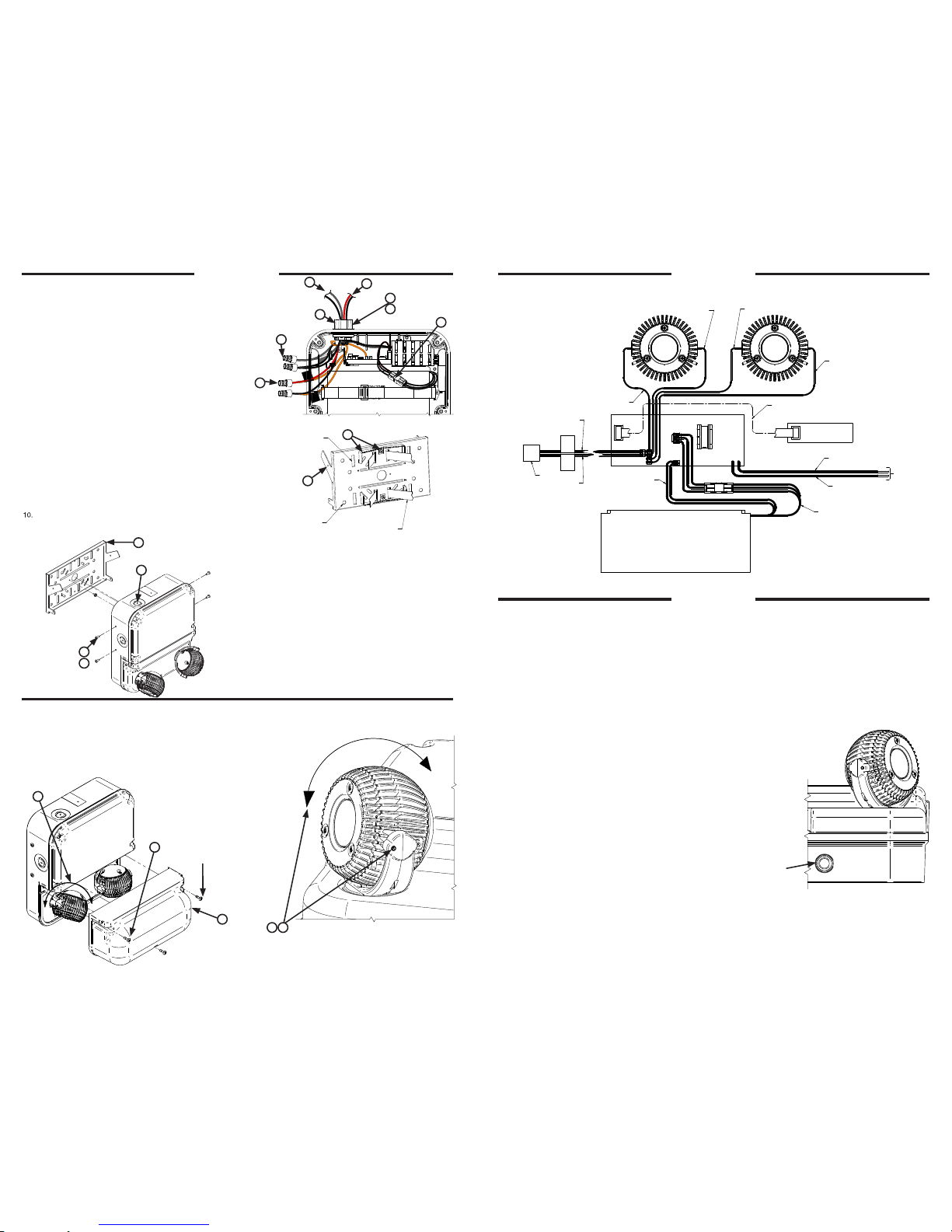
INSTALLATION INSTALLATION
Wall, Ceiling or Pole Mounting
Pole Mounting
1. Loosen the three captive screws on the clear cover.
2. Remove cover. (all models without clear cover skip step 1 & 2)
3 Rotate lamp heads to desired position.
4. Loosen set screws 2 per head and adjust axially on stem.
5. Lock set screws once desired position is set (hex wrench provided).
6. Reverse steps 2 &1 (if required).
NOTE: IF UNIT IS IN A WET LOCATION
ENVIRONMENT, ALL COVER SCREWS
ARE TO BE TORQUED TO 5-6 INCH
POUNDS OR UNTIL COVER SEATS WITH
HOUSING!
“DO NOT OVER TIGHTEN SCREWS”
7X PLCS
DYN Wiring Diagram
Lamp Head Adjustment
93055897
93061887
93055892
93055893
93055812
***Once remote capacity base models DYN12 or DYN12I have been installed press and
hold the test button for more than 5 seconds to initiate the “LOAD LEARN” process.***
“AC ON” LED is illuminated when AC power is present.
NOTE: All models are supplied with an AC Lockout circuit, which prevents the emergency lights from illuminating when the
battery is connected and no AC power is present.
NOTE: All models are supplied with Low Voltage Disconnect circuit, which prevents damage to the battery from deep discharge
during prolonged emergency operation.
NOTE: Batteries are often shipped in a discharged state – this is normal. The battery will require charging. Allow 24 hours of
charging before testing the unit.
Models without SPECTRON® Self-Diagnostic
Models without Spectron® self diagnostic electronics system provide:
• Visual indication of AC power status
Visual indication of any unit malfunctions include –
• Battery Disconnected
• Charger Fault
Models with SPECTRON® Self-Testing/Self-Diagnostic Circuitry
Models equipped with the Spectron® self-testing/self-diagnostic electronics system provide:
• Visual indication of AC power status
• Visual indication on self-diagnostic status and results
Visual indication of any unit malfunctions include –
• Battery Disconnected
• Battery Fault
• Charger Fault
• LED Driver Fault
• Lamp Fault
• Load Learn Failure
Spectron equipped units also include:
Browout protection: Unit will automatically transfer to emergency operation upon detection of low AC power
(approximately 80% of nominal line.)
Time Delay Retransfer: upon return of normal AC power, unit will remain in emergency mode for an additional
15 minutes to allow AC power to stabilize.
OPERATION
1. The DYN mounting plate can be mounted directly to a wall, ceiling or
pole (using appropriate hardware).
2. Once mounting plate is secured, you can hang the DYN Industrial Unit
and add security screws (qty 4).
3. If the DYN unit is mounted to the ceiling the 4 security screws are to be
added to keep the unit secure to the mounting plate.
4. Feed the AC power leads through the hub assembly (provided).
Hubs are provided with ground lug for entrance of AC power supply.
Following nal conductor routing, use a thread sealant in the conduit-to
hub joint to maintain maximum environmental protection. Note: hub(s)
must be grounded.
5. Install and connect Listed remote lighting xture(s) (if applicable). Note
connections on the wiring diagram in this document. Note: hub(s) must
be grounded.
6. Only use UL Listed water tight conduit ttings that meet the
requirements of the UL 514B Standard for Conduit Tubing and Cable
Fittings when using (K.O.’s see note 5).
7. Connect wire from the unit to the building leads and secure with
wire nuts.
8. For remote capable DYN models, cut ORANGE wire connector from
orange remote leads and strip ½ inch for both lead ends. Observe
proper polarity when connecting remote leads to remote xtures.
Pos. (+) to red remote xture lead and Neg. (-) to black remote
xture lead.
9. Connect battery pack harness to PCB charger harness.
10. For pole mounting used additional #8‐32 x ¼ long screws (qty 2) and
both toothed mounting brackets as shown. Banding straps are not
provided due to varying pole and column dimensions.
93055895
4 3
2 1
D
C
B
REV DATE RECORD DESN CHCK
ALBEC-121017003
6/12/14
1
ALB
ALB
ADDED WAGO ,EC-121017003
5/7/15
2
ALB
ORG
(POS +)
ORG
(NEG -)
RE
MOTE
LEAD (
-)
REMOT
E
LEAD (+
)
ORG
WIRE
CONN.
BLK (NEG -)
RED (POS +)
BLK (NEG -)
RIBBON
CABLE
SWITCH/LED PCB
CHARGER PCB
J2
J6
J5J10
J9
HEATER
HARNESS
(IF REQ)
WHT (COM)
BLK (HOT)
AC INPUT
BATTERY
HARNESS
HEATER/BATTERY
PACK
RED (POS +)
AC2
AC1
34
12
D
C
B
REV DATE RECORD DESN CHCK
ALBEC-121017003
6/12/14
1
ALB
21
D
C
B
REV DATE RECORD DESN CHCK
ALBEC-121017003
6/12/14
1
ALB
21
D
C
REV DATE RECORD DESN CHCK
ALBEC-121017003
6/12/14
1
ALB
43
21
D
C
B
REV DATE RECORD DESN CHCK
ALBEC-121017003
6/12/14
1
ALB
43
21
D
C
B
REV DATE RECORD DESN CHCK
ALB
EC-121017003
10/7/141
ALB
BANDING STRAP SLOT
8X PLCS 1 X 1/4 INCH
HARDWARE HOLE
8X PLCS 5/16 DIA.
TYPICAL BANDING STRAPS,
NOT PROVIDED
7
8
5
6
9
10
1
3
1
2
93055896
34
12
D
C
B
REV DATE RECORD DESNCHCK
ALB
EC-121017003
6/12/14
BLA1
Drill "W" (.397 dia)
UNIT CAN BE THREADED ROD MOUNTED
3/8 THREADED ROD IS RECOMMENDED
1
5
2
3
6
4
7
MTG PLATE MTG
HOLES 8X PLCS
5/16 DIA.
54
TEST
BUTTON
 Loading...