

Page 1
UFO-7W
Ni - Cd
INSTALLATION INSTRUCTIONS
! IMPORTANT SAFEGUARDS !
WHEN USING ELECTRICAL EQUIPMENT, BASIC SAFETY PRECAUTIONS SHOULD ALWAYS BE
FOLLOWED, INCLUDING THE FOLLOWING:
READ AND FOLLOW ALL SAFETY INSTRUCTIONS
1. To prevent high voltage from being present on red & yellow output leads prior to installation,
inverter connector must be open. Do not join inverter connector until installation is complete and
AC power is supplied to the emergency ballast.
2. This product is for use with most 2" through 8" (17 W - 215 W) T5, T8, T9, T10 and T12 single pin
or bipin fluorescent lamps, including energy saving, circline, U-shaped and rapid-start (4-pin) long
compact fluorescent lamps.
3. Make sure all connections are in accordance with the National Electrical Code and any local
regulations.
4. To reduce the risk of electric shock, disconnect both normal and emergency power supplies and
inverter connector of the emergency ballast before servicing.
5. This emergency ballast is for factory or field installation.
6. This product is suitable for damp locations where the ambient temperature is +5°C minimum,
+50°C maximum. Not suitable for heated air outlets and wet or hazardous locations.
7. An unswitched AC power source is required (120 or 277 VAC, 60 Hz).
8. Do not install near gas or electric heaters.
9. The use of accessory equipment not recommended by the manufacturer may cause an unsafe
condition.
10. Do not use this product for other than intended use.
11. Servicing should be performed by qualified service personnel.
CAUTION: Verify that all replacement lamp types marked on the installed luminaire are also identified as
suitable for use with this inverter/charger pack.
SAVE THESE INSTRUCTIONS
CONTAINS NICKEL-CADMIUM
RECHARGEABLE BATTERY.
MUST BE RECYCLED OR
DISPOSED OF PROPERLY.
WARNING – This product contains chemicals known to the State of California to cause cancer, birth defects and/or other
reproductive harm. Thoroughly wash hands after installing, handling, cleaning, or otherwise touching this product.
12/10/13
©
Hubbell Lighting, Inc. • 701 Millennium Blvd • Greenville, SC 29607 • (864) 678-1000 • FAX (864) 678-1415 • www.dual-lite.com
73000017
HUBBELL
Hubbell Lighting, Inc.
®
Page 2
INSTALLATION
WARNING: TO PREVENT HIGH VOLTAGE FROM BEING PRESENT ON RED AND YELLOW
OUTPUT LEADS PRIOR TO INSTALLATION, INVERTER CONNECTOR MUST BE OPEN. DO
NOT jOIN INVERTER CONNECTOR UNTIL INSTALLATION IS COMPLETE AND AC POWER
IS SUPPLIED TO THE EMERGENCY BALLAST.
NOTE: Before installing the emergency ballast, make sure that the necessary branch circuit wiring is
available. An unswitched source of power is required. The emergency ballast must be fed from the
same branch circuit as the AC ballast.
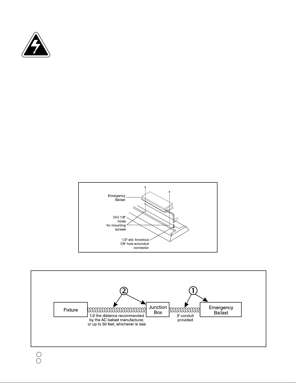
1. Disconnect AC power from the fixture. Install the emergency ballast either on top of the fixture (see Illustration
1) or remote from the fixture up to 1/2 the distance the AC ballast manufacturer recommends remoting the AC
ballast from the lamp, or up to 50 feet, whichever is less (see Illustration 2).
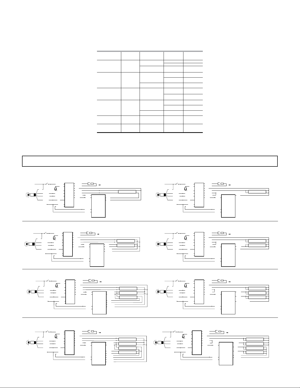
2. Select the appropriate wiring diagram to connect the emergency ballast to the AC ballast and lamp. Make sure
all connections are in accorance with the National Electrical Code and any local regulations.
3. Install the test switch/indicator light through the ballast channel cover of a troffer or through the side of a strip
fixture. Drill a 3/8" hole and install the test switch/indicator light as shown (see Illustration 3). Wire the test switch
so that it removes AC power from both the emergency ballast and the AC ballast at the same time (see wiring
diagrams).
4. In a readily visible location on the fixture, attach the label "CAUTION-This Unit Has More Than One Power Con-
nection Point. To Reduce The Risk Of Electric Shock, Disconnect Both The Branch Circuit-Breakers Or Fuses And
Emergency Power Supplies Before Servicing."
ILLUSTRATION 1
ILLUSTRATION 2
rEMOTE INSTALLATION
NOTE: Do not extend inverter connector leads (white and red), and lamp selector (brown) leads. These
connectors should be left in the junction box.
1 Emergency ballast with flexible conduit.
2 Conduit and junction box (not supplied), but necessary for remote installation.
2
Page 3
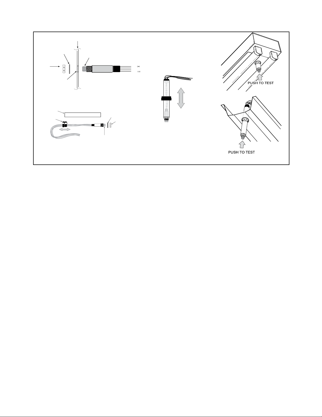
ILLUSTRATION 3
Lock
Washer
Hex Nut
Illuminated
Test Switch
Fixture or
Test/Monitor Plate
Violet
Black
Brown
Black
Drill or Punch
a 3/8” Hole
Plastic Tube
Washer
Indicator Light/Test Switch
Hex Nut
Strain Relief
Bushing
NOTE: After installing the test switch/indicator light, mark with the appropriate label.
5. After installation is complete, supply AC power to the emergency ballast and join the inverter connector.
6. A short-term discharge test may be conducted after the emergency ballast has been charging for one hour.
Charge for 24 hours before conducting a long-term discharge test. Refer to OPERATION.
OPERATION
When AC power is applied, the charging indicator light is illuminated, indicating that the battery is being charged.
When power fails, the emergency ballast automatically switches to emergency power, operating either one or two
lamps for at least 90 minutes. When AC power is restored, the emergency ballast returns to the charging mode and
delays AC ballast operation for approximately three seconds to prevent false-tripping of AC ballast (end-of-lamp-life
shutdown circuits.
MAINTENANCE
Although no routine maintenance is required to keep the emergency ballast functional, it should be checked
periodically to ensure that it is working. The following schedule is recommended:
1. Visually inspect the charging indicator light monthly. It should be illuminated.
2. Test the emergency operation of the fixture at 30-day intervals for a minimum of 30 seconds. Either one or two
lamps should operate for the duration of the test.
3. Conduct a 90-minute discharge test once a year. Either one or two lamps should operate for at least
90 minutes.
4. The life expectancy of the battery is 7 to 10 years.
REFER ANY SERVICING INDICATED BY THESE CHECkS TO QUALIFIED PERSONNEL.
3
Page 4
WIRING DIAGRAMS
WALL SWITCH
WALL SWITCH
WALL SWITCH
WALL SWITCH
WALL SWITCH
WALL SWITCH
EMERGENCY BALLAST AND AC BALLAST MUST BE FED FROM THE SAME BRANCH CIRCUIT.
TYPICAL SCHEMATICS ONLY. MAY BE USED WITH OTHER BALLASTS. CONSULT THE FACTORY FOR OTHER WIRING DIAGRAMS.
Table 1 - Lamp Compatibility
LAMP DIAMETER
(T8, T9, T10, T12)
1”, 1¼”, 1½”
Long Compact 4-PIN (2G11)
Twin/Quad
Twin-Tube Compact
2D
T5 Circline
T5 (5/8”) Bipin
BASE WATTAGE
Single
Bipin
4-PIN
(G24q, GX24q)
4-PIN
(GR10q)
4-PIN
(2Gx13)
17 - 40 W (2’ - 4’)
or
40 - 215 W (5' -8') 1 OPEN
(Length)
18 - 39 W
NO. of LAMPS
(EMERGENCY)
1 CLOSED
2 OPEN
1 CLOSED
2 OPEN
BROWN
CONNECTOR
40 - 55 W 1 OPEN
18 - 42 W
16 - 38 W
1 CLOSED
2 OPEN
1 CLOSED
2 OPEN
55 W 1 OPEN
22 - 55 W 1 CLOSED
21 - 54 W
(2’ - 4’)
1 CLOSED
Important: Refer to Table 1 before
connecting the brown connector.
WIRING DIAGRAMS for 1-LAMP emergency operation
FIG A ONE (1) LAMP RAPID START BALLAST
WALL SWITCH
HOT
BLK
ITS
COMMON
INVERTER
CONNECTOR
VIOLET
BROWN
BLACK
WHT/RED
RED
WHITE
VIOLET(+)
BROWN(-)
BLACK 120V
OR
ORANGE 277V
(CAP UNUSED LEAD)
WHITE
WHT/BLK
BROWN
BROWN
E
RED
M
B
E
YELLOW
A
R
L
YEL/BLK
G
L
E
A
N
S
C
T
Y
BLU/WHT
BLUE
BLUE
BLUE
BLACK
WHITE
1 LAMP
RAPID START
BALLAST
WARNING: Refer to Table 1
RED
RED
FIG C TWO (2) LAMP RAPID START BALLAST
HOT
BLK
ITS
COMMON
INVERTER
CONNECTOR
VIOLET
BROWN
BLACK
WHT/RED
WHITE
VIOLET(+)
BROWN(-)
BLACK 120V
OR
ORANGE 277V
(CAP UNUSED LEAD)
WHITE
WHT/BLK
RED
BROWN
BROWN
E
RED
M
B
E
YELLOW
A
R
L
YEL/BLK
G
L
E
A
N
S
C
T
Y
BLU/WHT
BLUE
BLUE
BLUE
BLACK
WHITE
WARNING: Refer to Table 1
2 LAMP
RAPID
START
BALLAST
RED
RED
YELLOW
YELLOW
FIG C THREE (3) LAMP RAPID START BALLAST
HOT
BLK
ITS
COMMON
INVERTER
CONNECTOR
VIOLET
BROWN
BLACK
WHT/RED
WHITE
VIOLET(+)
BROWN(-)
BLACK 120V
OR
ORANGE 277V
(CAP UNUSED LEAD)
WHITE
WHT/BLK
RED
BROWN
BROWN
E
RED
M
B
E
YELLOW
A
R
L
YEL/BLK
G
L
E
A
N
S
C
T
Y
BLU/WHT
BLUE
BLUE
BLUE
BLACK
WHITE
WARNING: Refer to Table 1
3 LAMP
RAPID
START
BALLAST
YELLOW
YELLOW
RED
RED
BLU/WHT
BLU/WHT
LAMP
LAMP (EMERGENCY)
LAMP
LAMP (EMERGENCY)
LAMP
LAMP
FIG B ONE (1) LAMP INSTANT START BALLAST
WALL SWITCH
HOT
BLK
ITS
COMMON
INVERTER
CONNECTOR
VIOLET
BROWN
BLACK
WHT/RED
RED
WHITE
VIOLET(+)
BROWN(-)
BLACK 120V
OR
ORANGE 277V
(CAP UNUSED LEAD)
WHITE
WHT/BLK
BROWN
BROWN
E
RED
M
B
E
YELLOW
A
R
L
YEL/BLK
G
L
BLU/WHT
E
A
N
S
C
T
Y
BLUE
BLUE
BLACK
WHITE
WARNING: Refer to Table 1
1 LAMP
INSTANT
START
BALLAST
RED
FIG D TWO (2) LAMP INSTANT START BALLAST
HOT
BLK
ITS
COMMON
INVERTER
CONNECTOR
VIOLET
BROWN
BLACK
WHT/RED
RED
WHITE
VIOLET(+)
BROWN(-)
BLACK 120V
OR
ORANGE 277V
(CAP UNUSED LEAD)
WHITE
WHT/BLK
BROWN
BROWN
E
RED
M
B
E
YELLOW
A
R
L
YEL/BLK
G
L
BLU/WHT
E
A
N
S
C
T
Y
BLUE
BLUE
BLACK
WHITE
WARNING: Refer to Table 1
2 LAMP
INSTANT
START
BALLAST
BLUE
RED
LAMP (EMERGENCY)
FIG D THREE (3) LAMP INSTANT START BALLAST
HOT
BLK
ITS
COMMON
INVERTER
CONNECTOR
VIOLET
BROWN
BLACK
WHT/RED
RED
WHITE
VIOLET(+)
BROWN(-)
BLACK 120V
OR
ORANGE 277V
(CAP UNUSED LEAD)
WHITE
WHT/BLK
BROWN
BROWN
E
RED
M
B
E
YELLOW
A
R
L
YEL/BLK
G
L
BLU/WHT
E
A
N
S
C
T
Y
BLUE
BLUE
BLACK
WHITE
WARNING: Refer to Table 1
3 LAMP
INSTANT
START
BALLAST
BLUE
BLUE
RED OR YELLOW
LAMP (EMERGENCY)
LAMP
LAMP
LAMP
LAMP
FIG E FOUR (4) LAMP RAPID START BALLAST
BROWN
BROWN
E
RED
M
B
YELLOW
E
A
YEL/BLK
R
L
G
L
E
A
N
S
C
T
Y
BLU/WHT
BLUE
BLUE
BLUE
BLACK
WHITE
WARNING: Refer to Table 1 before connecting
4 LAMP
RAPID
START
BALLAST
HOT
BLK
ITS
COMMON
INVERTER
CONNECTOR
VIOLET
BROWN
BLACK
WHT/RED
RED
WHITE
VIOLET(+)
BROWN(-)
BLACK 120V
OR
ORANGE 277V
(CAP UNUSED LEAD)
WHITE
WHT/BLK
BLU/WHT
BLU/WHT
BLUE
BLUE
BROWN
BROWN
YELLOW
YELLOW
LAMP (EMERGENCY)
LAMP
LAMP
LAMP
FIG F FOUR (4) LAMP INSTANT START BALLAST
INVERTER
CONNECTOR
VIOLET
BROWN
BLACK
WHT/RED
RED
WHITE
VIOLET(+)
BROWN(-)
BLACK 120V
OR
ORANGE 277V
(CAP UNUSED LEAD)
WHITE
WHT/BLK
HOT
BLK
ITS
COMMON
BROWN
BROWN
E
RED
M
B
YELLOW
E
A
YEL/BLK
R
L
BLU/WHT
G
L
E
A
N
S
C
T
Y
BLUE
BLUE
BLACK
WHITE
WARNING: Refer to Table 1 before connecting
BLUE
RED
4 LAMP
RED
INSTANT
START
YELLOW
YELLOW
BALLAST
4
LAMP (EMERGENCY)
LAMP
LAMP
LAMP
Page 5
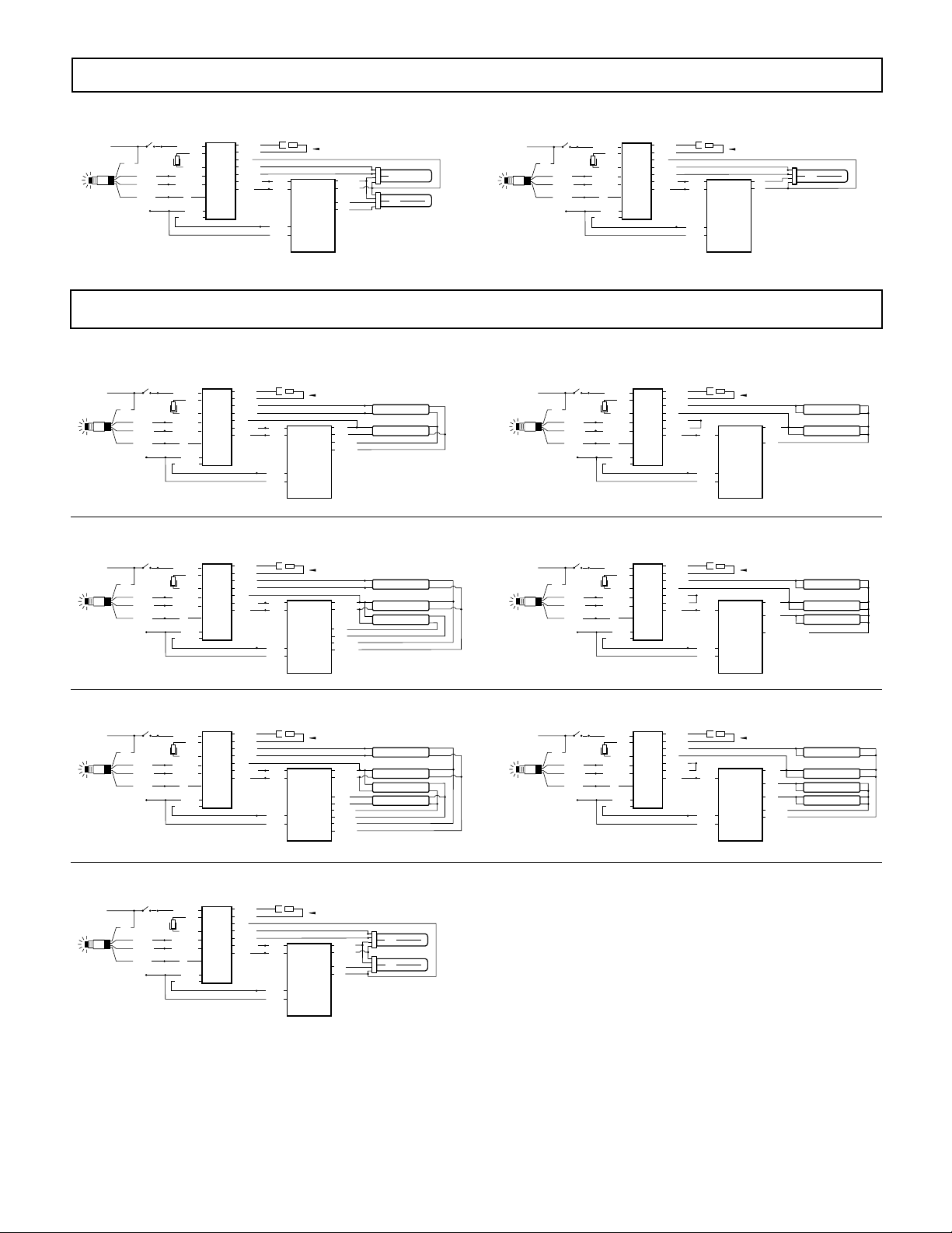
WIRING DIAGRAMS for 1-LAMP emergency operation
WALL SWITCH
WALL SWITCH
WALL SWITCH
WALL SWITCH
wn connector
FIG G TWO (2) 4-PIN COMPACT LAMP RAPID START BALLAST
WALL SWITCH
HOT
BLK
ITS
COMMON
INVERTER
CONNECTOR
VIOLET
BROWN
BLACK
WHT/RED
RED
WHITE
VIOLET(+)
BROWN(-)
BLACK 120V
OR
ORANGE 277V
(CAP UNUSED LEAD)
WHITE
WHT/BLK
BROWN
BROWN
E
RED
M
B
YELLOW
E
A
YEL/BLK
R
L
G
L
E
A
N
S
C
T
Y
BLU/WHT
BLUE
BLUE
BLUE
BLACK
WHITE
WARNING: Refer to Table 1 before connecting
YELLOW
YELLOW
2, 4-PIN
RED
COMPACT
RED
LAMP
RAPID
START
BALLAST
LAMP (EMERGENCY)
LAMP
FIG H ONE (1) 4-PIN COMPACT LAMP RAPID START BALLAST
WALL SWITCH
HOT
BLK
ITS
COMMON
INVERTER
CONNECTOR
VIOLET
BROWN
BLACK
WHT/RED
WHITE
VIOLET(+)
BROWN(-)
BLACK 120V
OR
ORANGE 277V
(CAP UNUSED LEAD)
WHITE
WHT/BLK
RED
BROWN
BROWN
E
RED
M
B
YELLOW
E
A
YEL/BLK
R
L
G
L
E
A
N
S
C
T
Y
BLU/WHT
BLUE
BLUE
BLUE
BLACK
WHITE
WARNING: Refer to Table 1 before connecting
RED
RED
1 4-PIN
COMPACT
LAMP
RAPID
START
BALLAST
LAMP
WIRING DIAGRAMS for 2-LAMP emergency operation (2'-4', 17-40 W lamps only)
FIG I TWO (2) LAMP RAPID START BALLAST
WALL SWITCH
HOT
BLK
ITS
COMMON
INVERTER
CONNECTOR
VIOLET
BROWN
BLACK
WHT/RED
WHITE
VIOLET(+)
BROWN(-)
BLACK 120V
OR
ORANGE 277V
(CAP UNUSED LEAD)
WHITE
WHT/BLK
RED
BROWN
BROWN
E
YELLOW
M
B
YEL/BLK
E
A
R
RED
L
G
L
E
A
N
S
C
T
Y
BLU/WHT
BLUE
BLUE
BLUE
BLACK
WHITE
WARNING: Do Not Connect
RED
RED
YELLOW
YELLOW
2 LAMP
RAPID
START
BALLAST
FIG K FOUR (4) LAMP RAPID START BALLAST
INVERTER
CONNECTOR
VIOLET
BROWN
BLACK
WHT/RED
WHITE
VIOLET(+)
BROWN(-)
BLACK 120V
OR
ORANGE 277V
(CAP UNUSED LEAD)
WHITE
WHT/BLK
RED
HOT
BLK
ITS
COMMON
BROWN
BROWN
E
YELLOW
M
B
YEL/BLK
E
A
R
RED
L
G
L
E
A
N
S
C
T
Y
BLU/WHT
BLUE
BLUE
BLUE
BLACK
WHITE
WARNING: Do Not Connect
YELLOW
YELLOW
3 LAMP
RED
RAPID
RED
START
BLU/WHT
BALLAST
BLU/WHT
LAMP
LAMP
LAMP (EMERGENCY)
LAMP (EMERGENCY)
LAMP
FIG J TWO (2) LAMP INSTANT START BALLAST
WALL SWITCH
HOT
BLK
ITS
COMMON
INVERTER
CONNECTOR
VIOLET
BROWN
BLACK
WHT/RED
WHITE
VIOLET(+)
BROWN(-)
BLACK 120V
OR
ORANGE 277V
(CAP UNUSED LEAD)
WHITE
WHT/BLK
RED
BROWN
BROWN
E
YELLOW
M
B
RED
E
A
R
L
YEL/BLK
G
L
BLU/WHT
E
A
N
S
C
T
Y
BLUE
BLUE
BLACK
WHITE
WARNING: Do Not Connect
2 LAMP
INSTANT
START
BALLAST
BLUE
RED
FIG L THREE (3) LAMP INSTANT START BALLAST
HOT
BLK
ITS
COMMON
INVERTER
CONNECTOR
VIOLET
BROWN
BLACK
WHT/RED
WHITE
VIOLET(+)
BROWN(-)
BLACK 120V
OR
ORANGE 277V
(CAP UNUSED LEAD)
WHITE
WHT/BLK
RED
BROWN
BROWN
E
YELLOW
M
B
RED
E
A
R
L
YEL/BLK
G
L
BLU/WHT
E
A
N
S
C
T
Y
BLUE
BLUE
BLACK
WHITE
WARNING: Do Not Connect
3 LAMP
INSTANT
START
BALLAST
BLUE
BLUE
RED OR YELLOW
LAMP
LAMP
LAMP (EMERGENCY)
LAMP (EMERGENCY)
LAMP
INVERTER
CONNECTOR
VIOLET
BROWN
BLACK
WHT/RED
WHITE
VIOLET(+)
BROWN(-)
BLACK 120V
OR
ORANGE 277V
(CAP UNUSED LEAD)
WHITE
WHT/BLK
RED
HOT
BLK
ITS
COMMON
BROWN
BROWN
E
YELLOW
M
B
E
YEL/BLK
A
R
L
RED
G
L
E
A
N
S
C
T
Y
BLU/WHT
BLUE
BLUE
BLUE
BLACK
WHITE
WARNING: Do Not Connect
BLU/WHT
BLU/WHT
4 LAMP
BLUE
RAPID
BLUE
START
BROWN
BALLAST
BROWN
YELLOW
YELLOW
LAMP (EMERGENCY)
LAMP (EMERGENCY)
FIG O TWO (2) 4-PIN COMPACT LAMP RAPID START BALLAST
WALL SWITCH
HOT
BLK
ITS
COMMON
INVERTER
CONNECTOR
VIOLET
BROWN
BLACK
WHT/RED
RED
WHITE
VIOLET(+)
BROWN(-)
BLACK 120V
OR
ORANGE 277V
(CAP UNUSED LEAD)
WHITE
WHT/BLK
BROWN
BROWN
E
RED
M
B
YELLOW
E
A
YEL/BLK
R
L
G
L
E
A
N
S
C
T
Y
BLU/WHT
BLUE
BLUE
BLUE
BLACK
WHITE
WARNING: Do Not Connect bro
YELLOW
YELLOW
2 4-PIN
RED
COMPACT
RED
LAMP
RAPID
START
BALLAST
LAMP
LAMP
NOTE: The emergency ballast must interrupt the switched or unswitched hot lead feeding
the AC ballast. Before beginning installation, consult these wiring diagrams.
LAMP
LAMP
FIG N FOUR (4) LAMP INSTANT START BALLASTFIG M FOUR (4) LAMP RAPID START BALLAST
HOT
BLK
ITS
COMMON
INVERTER
CONNECTOR
VIOLET
BROWN
BLACK
WHT/RED
WHITE
VIOLET(+)
BROWN(-)
BLACK 120V
OR
ORANGE 277V
(CAP UNUSED LEAD)
WHITE
WHT/BLK
RED
BROWN
BROWN
E
YELLOW
M
B
RED
E
A
R
L
YEL/BLK
G
L
BLU/WHT
E
A
N
S
C
T
Y
BLUE
BLUE
BLACK
WHITE
WARNING: Do Not Connect
4 LAMP
INSTANT
START
BALLAST
BLUE
RED
RED
YELLOW
YELLOW
LAMP (EMERGENCY)
LAMP (EMERGENCY)
LAMP
LAMP
5
Page 6
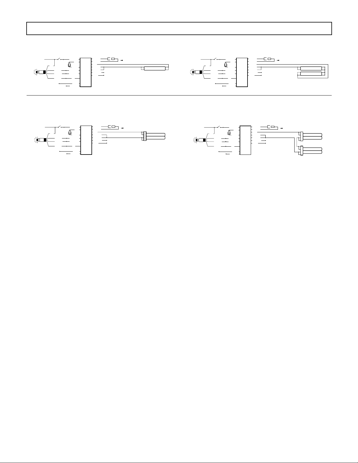
WIRING DIAGRAMS for Emergency-Only fixtures
WHT/BLK
WALL SWITCH
WHT/BLK
WALL SWITCH
WALL SWITCH
RED
YELLOW
YEL/BLK
BLU/WHT
BLUE
(CAP)
(CAP)
LAMP
WHITE
WHT/BLK
COMMON
E
M
E
R
G
E
N
C
Y
B
A
L
L
A
S
T
WARNING: Refer to Table 1
BROWN
BROWN
(CAP)
WALL SWITCH
WHT/RED
RED
WHITE
VIOLET(+)
BROWN(-)
(CAP UNUSED LEAD)
BLACK 120V
OR
ORANGE 277V
INVERTER
CONNECTOR
HOT
ITS
BLACK
BLK
BROWN
VIOLET
FIG P ONE (1) 17-215 W LAMP WITHOUT AC BALLAST
HOT
BLK
ITS
COMMON
INVERTER
CONNECTOR
VIOLET
BROWN
BLACK
WHT/RED
RED
WHITE
VIOLET(+)
BROWN(-)
BLACK 120V
OR
ORANGE 277V
(CAP UNUSED LEAD)
WHITE
(CAP)
BROWN
BROWN
E
RED
M
B
E
YELLOW
A
R
L
YEL/BLK
G
L
E
A
N
S
C
T
Y
BLU/WHT
BLUE
(CAP)
(CAP)
WARNING: Refer to Table 1
LAMP
FIG R ONE (1) 4-PIN COMPACT LAMP WITHOUT AC BALLAST
(16-55W)
FIG Q TWO (2) T8 OR T12 17-40 W LAMPS WITHOUT AC BALLAST
HOT
BLK
ITS
COMMON
INVERTER
CONNECTOR
VIOLET
BROWN
BLACK
WHT/RED
RED
WHITE
VIOLET(+)
BROWN(-)
BLACK 120V
OR
ORANGE 277V
(CAP UNUSED LEAD)
WHITE
(CAP)
BROWN
BROWN
E
RED
M
B
E
YELLOW
A
R
L
YEL/BLK
G
L
E
A
N
S
C
T
Y
BLU/WHT
BLUE
(CAP)
(CAP)
WARNING: Refer to Table 1
LAMP
LAMP
FIG S TWO (2) 4-PIN COMPACT LAMPS WITHOUT AC BALLAST
(16-42W)
HOT
BLK
ITS
COMMON
INVERTER
CONNECTOR
VIOLET
BROWN
BLACK
WHT/RED
RED
WHITE
VIOLET(+)
BROWN(-)
BLACK 120V
OR
ORANGE 277V
(CAP UNUSED LEAD)
WHITE
(CAP)
WHT/BLK
BROWN
BROWN
E
RED
M
B
E
YELLOW
A
R
L
YEL/BLK
G
L
BLU/WHT
E
A
BLUE
N
S
C
T
Y
(CAP)
(CAP)
WARNING: Refer to Table 1
LAMP 1
LAMP 2
6
 Loading...