

Page 1
XR-LASER GREEN
User’s Manual Rel 1.2
D.T.S. Illuminazione srl - ITALY
http://www.dts-lighting.it
GB
Made in Italy
Page 2

2
Le informazioni contenute in questo documento sono state attentamente redatte e controllate. Tuttavia
non è assunta alcuna responsabilità per eventuali inesattezze. Tutti i diritti sono riservati e questo
documento non può essere copiato, fotocopiato, riprodotto per intero o in parte senza previo consenso
scritto della D.T.S .
DTS si riserva il diritto di apportare senza preavviso cambiamenti e modifiche estetiche , funzionali o di
design a ciascun proprio prodotto. D.T.S non assume alcuna responsabilità sull’uso o sull’applicazione dei
prodotti o dei circuiti descritti.
The information contained in this publication has been carefully prepared and checked. However, no
responsibility will be taken for any errors. All rights are reserved and this document cannot be copied,
photocopied or reproduced, in part or completely, without prior written consent from D.T.S.
D.T.S. reserves the right to make any aesthetic, functional or design modifications to any of its products
without prior notice. D.T.S. assumes no responsibility for the use or application of the products or circuits
described herein.
XR-LASER GREEN
Les informations contenues dans le présent manuel ont été rédigées et contrôlées avec le plus grand
soin. Nous déclinons toutefois toute responsabilité en cas d'éventuelles inexactitudes. Tous droits
réservés. Ce document ne peut être copié, photocopié ou reproduit, dans sa totalité ou partiellement,
sans le consentement préalable de .
D.T.S.
de design, sans préavis, à chacun de ses produits. décline toute responsabilité sur l'utilisation ou
Todos los derechos han sido reservados y este documento no puede ser copiado, fotocopiado
D.T.S.
estético, funcional o de diseño a cada producto suyo. no se asume responsabilidad de
se réserve le droit d'apporter toutes modifications et améliorations esthétiques, fonctionnelles ou
D.T.S.
sur l'application des produits ou des circuits décrits.
Las informaciones contenidas en este documento han sido cuidadosamenteredactadas y
controladas. Con todo, no se asume ninguna responsabilidad por eventuales inexactitudes.
o reproducido, total o parcialmente, sin previa autorizaciónescrita de
se reserva el derecho a aportar sin previo aviso cambios y modificaciones de carácter
D.T.S.
ningún tipo sobre la utilización o sobre la aplicació
n de los productos o de los circuitos descritos.
D.T.S
D.T.S.
Page 3

3
XR-LASER GREEN
INDEX:
1- TECHNICAL FEATURES 4
2- IMPORTANT SAFETY INFORMATION 5
2.1 Fire prevention
2.2 Prevention of electric shock
2.3 Protection against direct exposure to laser beam
2.4 Safety
2.5 Level of protection against the penetration of solid and liquid objects
3- VOLTAGE AND FREQUENCY 6
4- INSTALLATION 6
4.1 Safety cable
4.2 Protection against liquids
4.3 Movement
4.4 Risk of fire
4.5 Forced ventilation
4.6 Ambient temperature
5- MAINS CONNECTION 7
5.1 Protection
6- DMX SIGNAL CONNECTION 8
6.1 DMX Addresses
6.2 Selecting the DMX address
7- DISPLAY FUNCTIONS 10
8- PAN & TILT SPEED 13
9- FANS SPEED
10- ERROR MESSAGES 13
11- HIDDEN MENU 13
12- OPENING THE PROJECTOR HOUSING 14
13- PERIODIC CLEANING 14
13.1 Lenses and reflectors
13.2 Fans and air passages
14- PERIODIC CONTROLS
15- DMX PROTOCOL 15
16- DISPLAY + 2 MOTORS CARD 22
17- WIRING DIAGRAM 23
18- LASER MEDIA DESIGNER QUICK STEP GUIDE 24
19- SD CARD CATEGORIZER QUICK STEP GUIDE 28
Page 4
4
XR-LASER GREEN
1- TECHNICAL FEATURES
The XR-LASER GREEN is fitted with a 300 mW DSPP green color laser
Average laser lifespan is 8000 hours.
The unit incorporates:
Electronic Zoom system (4°-28°)
Dimmer (emitted light is controlled by progressive and linear dimming).
Strobe: Electronic strobe effect (frequency variable from 0.85 flashes/sec to 10
flashes/sec).
Prism (electronic indexable multistep prism rotating in both directions).
Pan: 540° in 2.8 seconds (8 or 16 bit) with auto repositioning system.
Tilt: 270° in 2.0 seconds (8 or 16 bit) with auto repositioning system.
USITT Standard DMX 512 input signal.
11 or 18 DMX channels.
4 -eight digit- LED display with 4 buttons.
4 XLR connectors (In and Out) with 3 and 5 pins.
SD card input socket (Graphics media)
USB connector (Software upgrade)
Power supply
Universal power supply 90-260V AC (50/60 Hz).
Power consumption: 150 W
Operating ambient temperature: 10° / 40°C
Weight: 16 Kg
Laser specifications
Output Power: 300 mW
Output wavelenght: 532 nm
Beam mode: TEM
00
Power stability: <5% (over 2 hours)
Beam divergence: <1.2mrad
Beam diameter: <1.5mm
Warmup time: <15 minutes
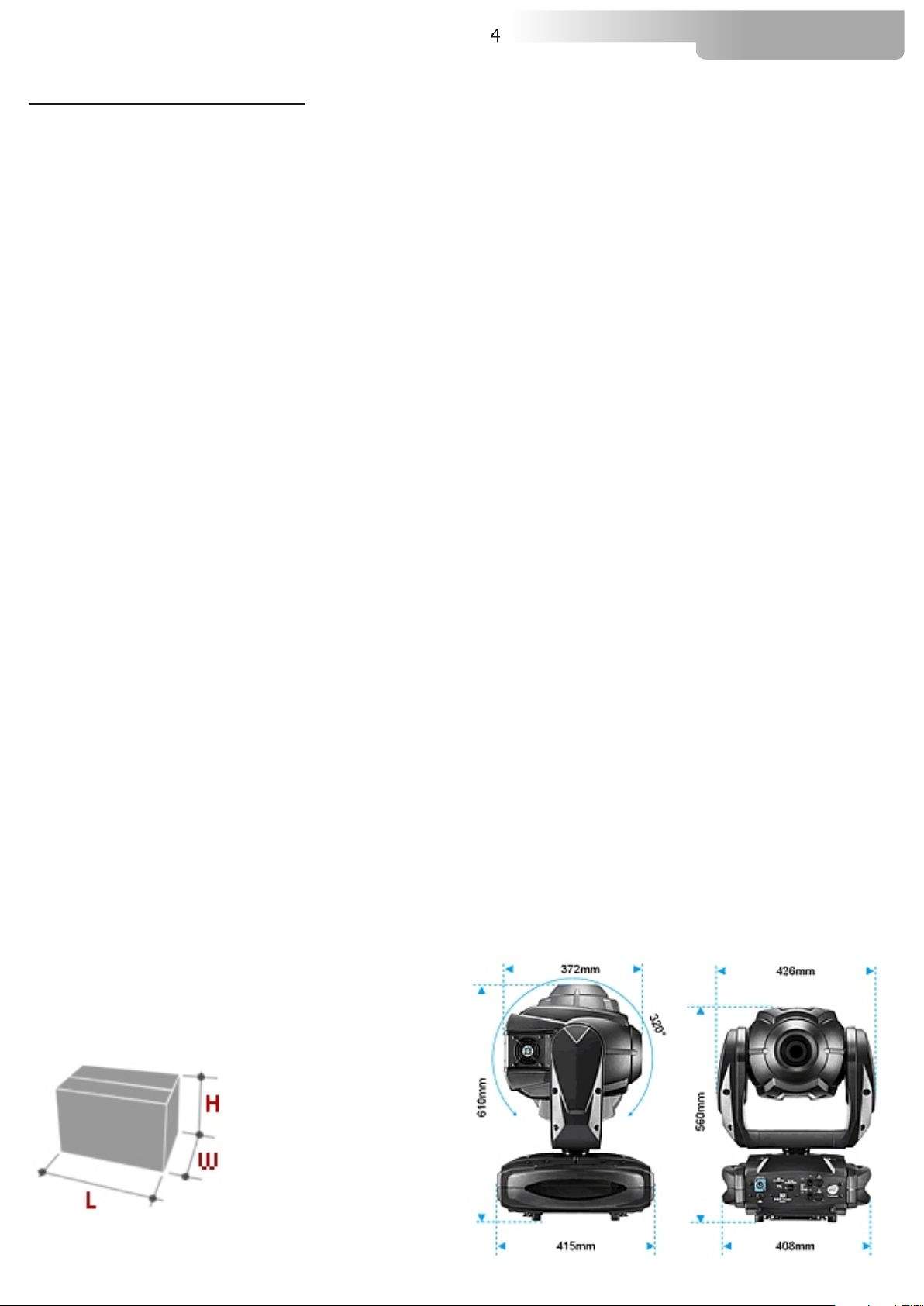
Packaging Dimensions
(LxWxH)
550 x 440 x 800 mm
Weight
21 Kg
Dimensions (LxWxH)
projector (426x415x610mm)
Page 5
2- IMPORTANT SAFETY INFORMATION
2.1 Fire prevention:
5
XR-LASER GREEN
XR-LASER GREEN is fitted with a 300 mW DSPP green color laser
.
-Minimum distance from flammable materials: 1 MT.
-Minimum distance from the closest illuminable surface: 2 MT.
-Replace any blown or damaged fuses only with those of identical value. Refer to the wiring diagram if
there is any doubt.
-Connect the projector to mains power via a thermal magnetic circuit breaker.
2.2 Prevention of electric shock:
-High voltage is present inside the unit. Unplug the unit prior to performing any function which involves
touching the inside of the moving head.
-The level of technology inherent in the XR-LASER GREEN requires the assistance of specialised
personnel for all servicing.Please refer to an authorised DTS service centre.
-A good earth connection is essential for proper functioning of the projector.
-Never connect the unit without proper earth connection.
-The fixture should be located in places with a good air ventilation.
2.3 Protection against direct exposure to laser beam:
-NO PERSON OTHER THAN A THROUGLY TRAINED OPERATOR SHOULD BE ALLOWED TO
USE THE LASER UNIT OR DIRECT OR MANIPULATE THE OUTPUT BEAM.
-Never turn on the unit if any of the lenses, filters or ABS covering is damaged. Their respective
shielding functions will only operate efficiently if they are in perfect working order.
A laser is an electronic-optical device that emits coherent light radiation,in a narrow, low-divergence
monochromatic beam with a well-defined wavelength. In this respect, laser light is in sharp contrast with
such light sources as the incandescent light bulb, which emits light over a wide area and over a wide
spectrum of wavelengths.
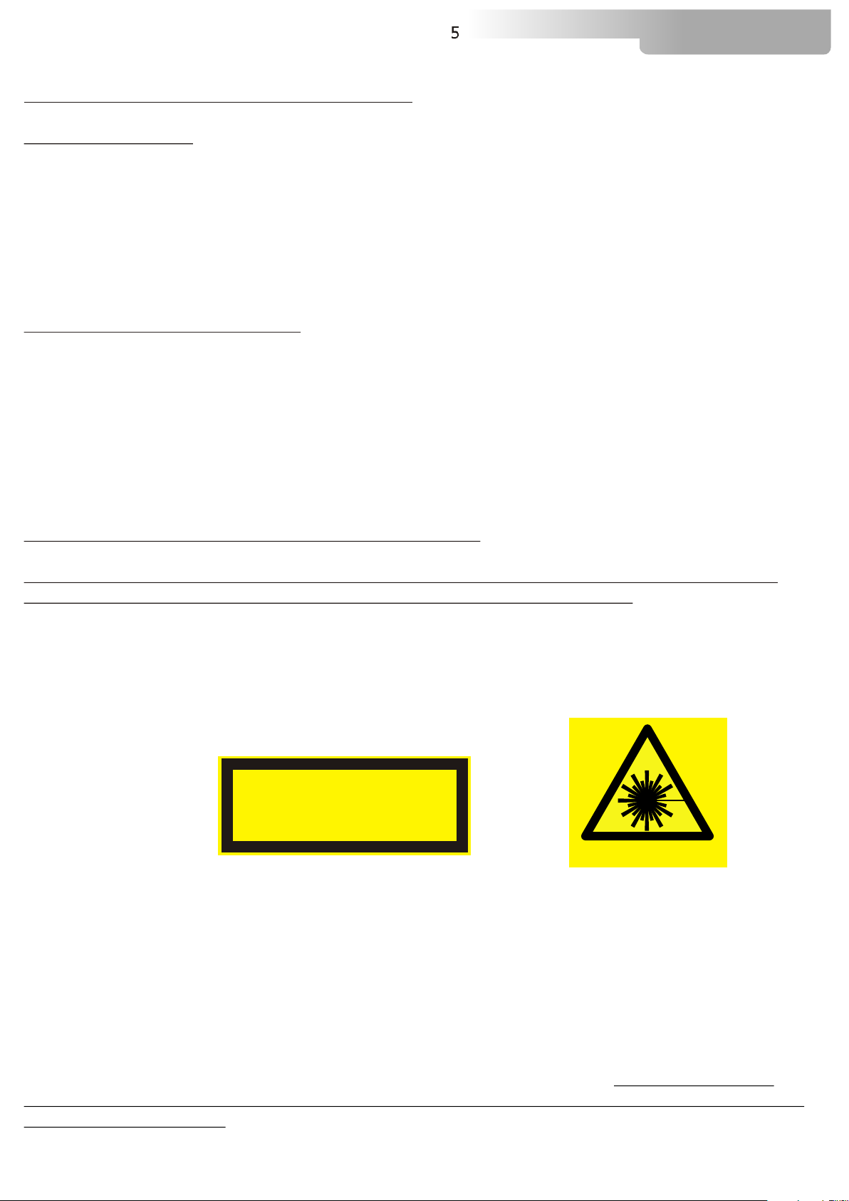
LASER RADIATION
AVOID EXPOSURE TO THE BEAM
CLASS 3B LASER PRODUCT
Class 3B laser
A Class 3B laser is hazardous if the eye is exposed directly.
Lasers in this category can cause permanent
LASER RADIATION
eye damage with exposures of 1/100th of a second or less depending on the strength of the
laser.D
iffuse reflections such as from paper or other matte surfaces are not harmful.Protective eyewear
is typically required where direct viewing of a class 3B laser beam may occur.
Protective eyewear in the form of spectacles or goggles with appropriately filtering optics can protect the
eyes from the reflected or scattered laser light with a hazardous beam power, as well as from direct
exposure to a laser beam. Eyewear must be selected for the specific type of laser, to block or attenuate
in the appropriate wavelength range.In addition to an optical density sufficient to reduce beam power to
below the maximum permissible exposure, laser eyewear used where direct beam exposure is possible
should be able to withstand a direct hit from the laser beam without breaking.
In an environment
with potential exposure to laser beams, suitable eye protection is recommended for beams
of Class 3B and Class 4.
In the U.S., guidance for the use of protective eyewear, and other elements of
safe laser use, is given in the ANSI Z136 series of standards. In the European Community, eye
protection requirements are specified in European norm EN 207.
Page 6
6
2.4 Safety:
-The projector should always be installed with bolts, clamps and other tools that are capable of
supporting the weight of the unit.
-Always use a second safety cable to sustain the weight of the unit in case of the failure of the main
fixing point.
-Never install the fixture in an enclosed area lacking sufficient air flow. The ambient temperature should
not exceed 40°C.
2.5 Level of protection against the penetration of solid and liquid objects:
-The projector is classified as an ordinary appliance and its protection level against the penetration of
solid and liquid objects is IP 20.
XR-LASER GREEN
3- VOLTAGE AND FREQUENCY
The can operate at 90-260 VOLT AC 50-60 Hz.
XR-LASER GREEN
4- INSTALLATION
XR-LASER GREEN
For floor mounting installations, the is supplied with four rubber mounting feet
under the base.
For ceiling mounted installations, we reccomend the use of appropriate clamps to fix the unit to the
mounting surface.
The supporting structure from which the unit is hung should be capable of bearing the weight of the
unit, as should any clamps used to hang it. The structure should also be sufficiently rigid so as not to
move or shake whilst the unit is moving.
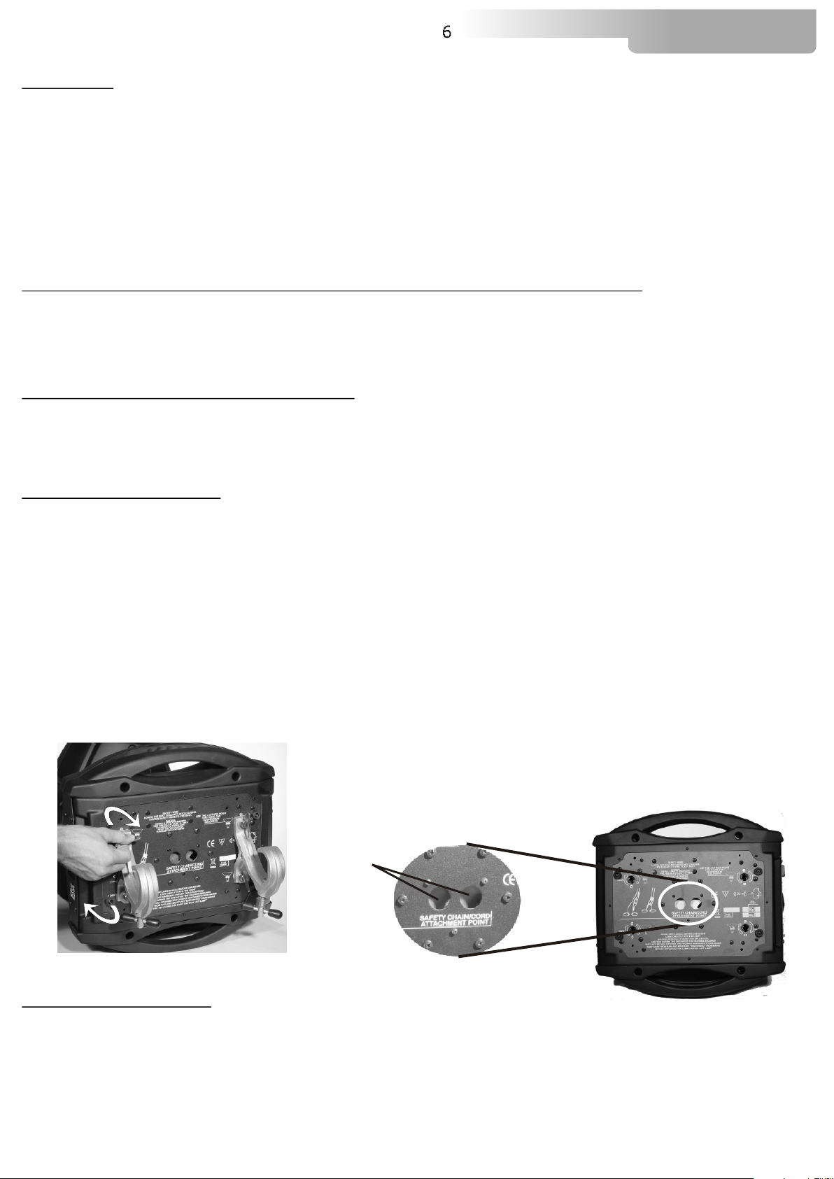
Four quarter turn fast locks placed on the base, allow to fix the unit in any position, by using the two fast
lock C clamps provided in the box.
may be either floor or ceiling mounted.
XR-LASER GREEN
A
4.1- Safety cable
We recommend the use of a safety cable or chain connected to the and to the
suspension truss in order to avoid the fixture accidentally falling should the main fixing point fail. Make
sure that the iron cable or chain can bear the weight of the entire unit.
You may attach the safety chain to the two holes (A) located on the base of the fixture, as shown in the
picture above.
XR-LASER GREEN
Page 7
7
XR-LASER GREEN
4.2- Protection against liquids
The projector contains electric and electronic components which should under no circumstances come
into contact with oil, water or any other liquid. The proper unit functioning would be compromised should
this occur.
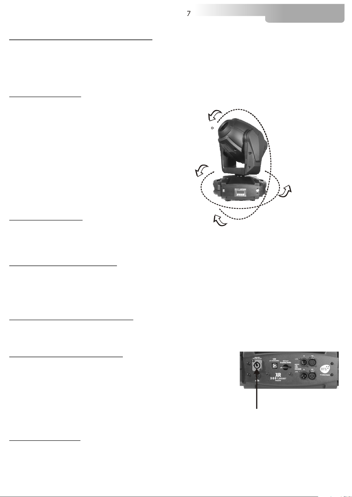
4.3- Movement
The projector has a maximum movement of 540° for Pan and 270° for Tilt. DO NOT place any
obstructions in the path of the projector's movement.
270°
540°
4.4- Risk of fire
Each fixture produces heat and must be installed in a well-ventilated place. The minimum recommended
distance from flammable material is 1 MT.
Minimum distance from the object being illuminated is 2 MT.
4.5- Forced ventilation
You will note, on inspection, that the unit features various air inlets and cooling fans located on both the
base and head of the fixture. These should, under no circumstances, be blocked or obstructed whilst the
projector is in operation.
Doing so could cause the fixture to seriously overheat thereby compromising its proper operation.
4.6- Ambient temperature
The projector should never be installed in places that lack a constant air flow. The ambient temperature
should NOT exceed 40°C.
5- MAINS CONNECTION
XR-LASER GREEN
Prior to connecting the unit to your mains supply,
ensure that the model in your possession correctly matches
the mains supply available. For connection purposes,
ensure that your plug is capable of supporting 3,15 amps at 230V
or 6 amps at 110V.
Strict adherence to regulatory norms is strongly recommended.
operates at 90-260 VOLT AC 50-60 Hz.
90-260V 50 / 60Hz
5.1- Protection
The use of a thermal magnetic circuit breaker is recommended for each .
A good earth connection is essential for the correct operation of the projector.
XR300 Laser
Page 8
8
XR-LASER GREEN
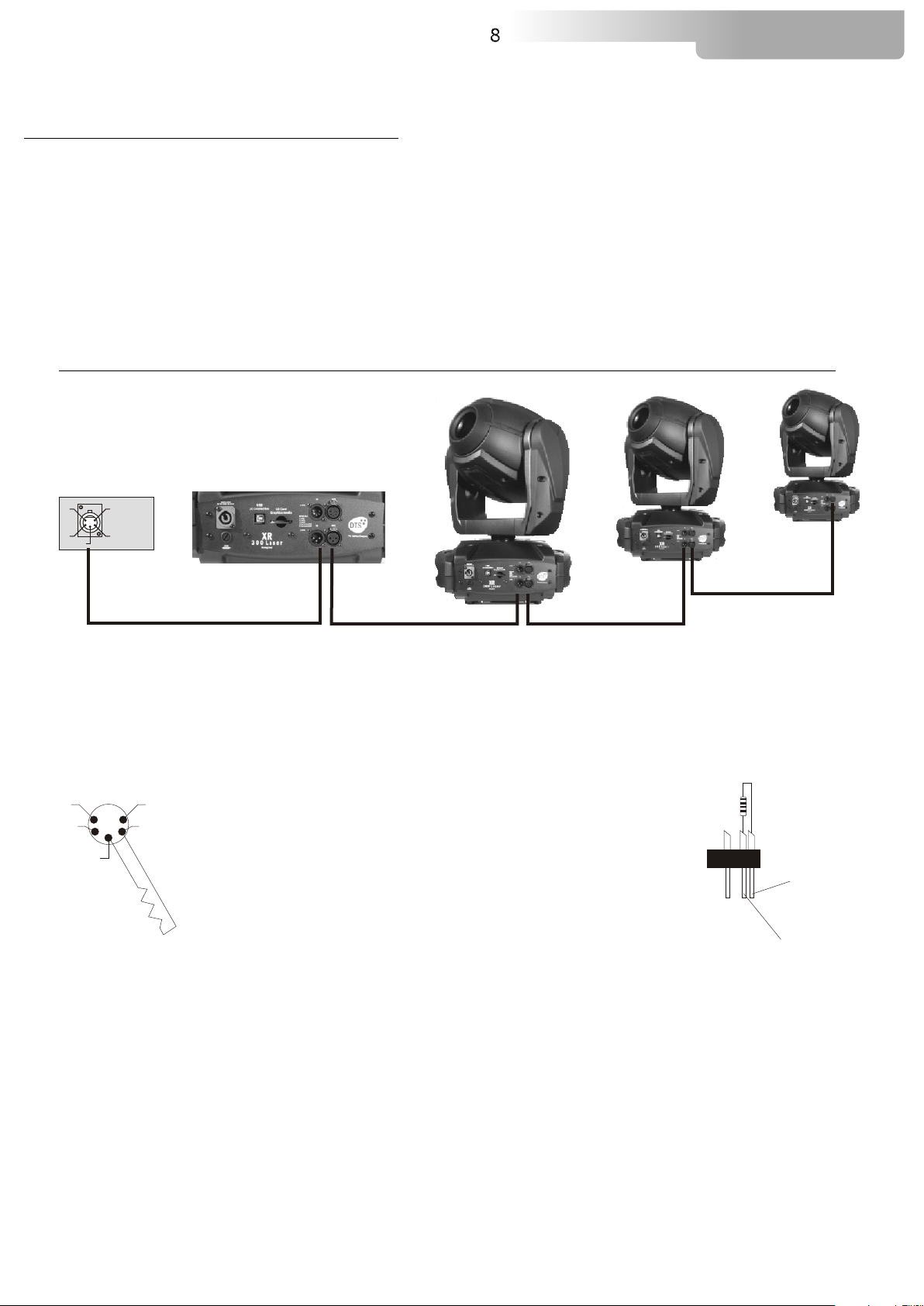
6- DMX SIGNAL CONNECTION
The unit operates using the digital DMX 512 (1990) signal. Connection between the mixer and the
projector or between projectors must be carried out using a two pair screened ø 0.5 mm cable and a
CANNON XLR 5 or 3 pins connector.
Ensure that the conductors do not touch each other.Do not connect the cable ground to the XLR chassy
The plug housing must be isolated. Connect the mixer signal to the DMX IN projector plug and connect it
to the next projector by connecting the DMX OUT plug on the first projector to the DMX IN plug of the
second one.
This way, all the projectors are cascade connected.
NB. If the display showing the DMX address flashes, then one of the following errors has occurred:
- DMX signal not present
- DMX address not valid
- DMX reception problem
CONTROLLER
S TA ND AR D
D M X 5 1 2
5
1
1=GND
2=DATA3=DATA+
4 2
3
For Installations where long distance DMX cable connections are needed, we suggest to use a DMX
terminator.
The DMX terminator is a male XLR 3-5 pins connector with a 120 ohm resistor
Between pin 2 and 3.
The DMX terminator must be plugged into the last unit (DMX out panel connector) of the DMX line.
5
4
120 ohm
1
2
3
OUT
PLACE A 120 OHM RESISTOR BETWEEN PIN 2
AND 3 OF A MALE XRL CONNECTOR AND PLUG IT
INTO THE DMX OUT PANEL CONNECTOR OF THE
LAST UNIT CONNECTED TO THE DMX LINE
PIN 3
PIN 2
Page 9

6.1-DMX Addresses
9
XR-LASER GREEN
XR-LASER GREEN
If you want to use the in 11 channels mode, select the 11 CH mode from the MODE
menu and set the following addresses on the mixer:
Projector 1 A001
Projector 2 A011 If you want to select the next projector, just add “11”
Projector 3 A023
….. A….
projector 6 A056
If you want to use the XR 300 Laser in 18 channels mode, select the 18 CH mode from the MODE menu
and set the following addresses:
Projector 1 A001
Projector 2 A019 If you want to select the next projector, just add “18”
Projector 3 A037
….. A….
Projector 6 A091
can be used in two different modes: 11 or 18 DMX (default) channels.
XR300 Laser
6.2-Selecting the DMX address
1) Press the UP-DOWN key until you reach the required DMX channel. The numbers on the display will
start to flash (but the new DMX address hasn't yet been set).
2) Press ENTER to confirm your selection. The numbers on the display will stop flashing and the
projector is now set to the new DMX address.
TRICKS:
if you keep pushed the UP or DOWN keys, the channels are calculated more quickly and you get a
faster selection.
Page 10
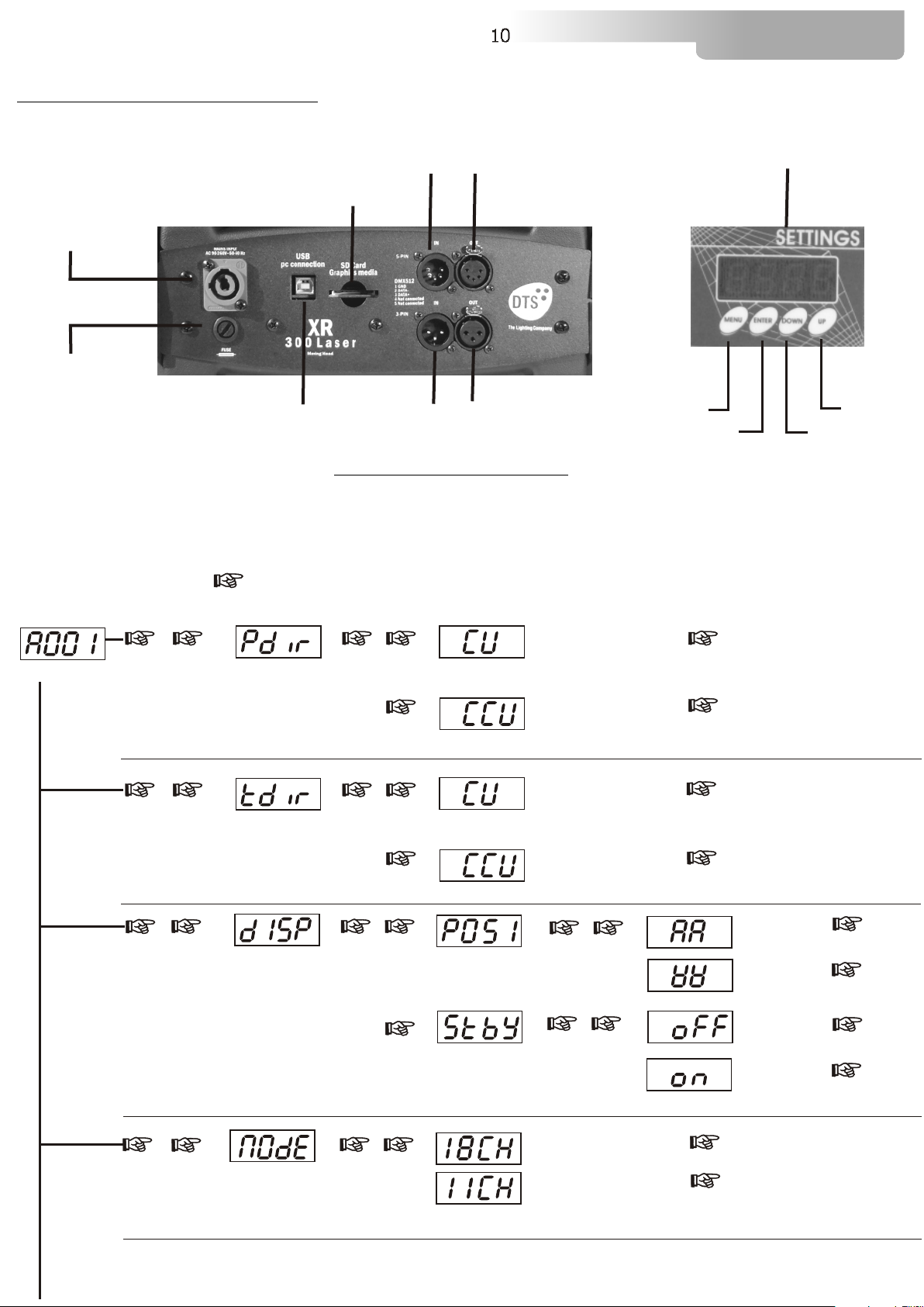
7- DISPLAY FUNCTIONS
10
XR-LASER GREEN
DMX OUT
DISPLAY
MAINS
DMX IN
SD CARD READER
90-260V 50 / 60Hz
FUSE
6 A
USB PORT
DMX IN
DMX OUT
MENU
ENTER
DOWN
DISPLAY FUNCTIONS
XR-LASER GREEN
The display panel shows all the available functions . Using these functions, it is
possible to change some of the parameters on the unit. Changing the DTS settings can vary the
functions of the unit so that it does not respond to the DMX 512 used to control it. Carefully
follow the instructions below before carrying out any variations or selections.
NOTE: the symbol shows which key has to be pushed to obtain the desired function.
UP
PAN MOVEMENT INVERSION
To reverse Pan movement from left
to right and vice versa
TILT MOVEMENT INVERSION
To reverse Tilt movement from
bottom upwards and vice versa
MENU
REVERSE DISPLAY
To Reverse display's reading depending
on the mounting position
(On the ground or suspended).
DISPLAY STAND BY
To turn off the display (after 5 seconds)
Or leave it always on.
Up-DownMENU ENTERUp-Down
Up-Down
Up-DownMENU ENTERUp-Down
Up-Down
Up-Down
ENTERUp-Down
Clockwise
Counterclockwise
Clockwise
Counterclockwise
Up-DownENTER
ENTER
ENTER
ENTER
ENTER
Floor
position
ENTER
Suspension
ENTER
ENTER
Up-Down
position
Up-DownENTER
Display OFF
Display
always ON
ENTER
Up-Down
DMX MODE
To select DMX mode : 18 or 11
channels
Up-DownMENU ENTER
(Pan & Tilt 16 bit)
11 CHANNELS
(Pan & Tilt 16 bit)
18 CHANNELS
ENTER
ENTER
(DEFAULT)
Page 11

7- DISPLAY FUNCTIONS
11
XR-LASER GREEN
Up-Down
MENU ENTER
TEST MODE
Pan&Tilt test with no laser output.
Up-Down
MENU ENTER
AUTOMATIC MODE
Automatic demo games
MENU
Up-Down
ENTER
RESET
Total unit reset
MENU
Up-Down
ENTER
DEFAULT
To restore default setting
Up-Down
ENTER
pan and tilt movements.
Laser output is kept OFF for
safety reason,doing the fact that
during test, Pan and Tilt can
reach undesidered positions.
Not yet implemented
ENTER
RESET ENABLED VIA DMX
RESET DISABLED VIA DMX
TOTAL RESET
ENTER
This test is usefull for testing
ENTER
ENTER
ENTER
MENU
Up-Down
ENTER
SOFTWARE
Pan & Tilt and Laser software
Versions
MENU ENTER
Up-Down
Up-Down
FANS control
To control the fans speed
Up-Down
MENU ENTER
Up-Down
SPEED control
Pan & Tilt Speed control.
MENU
Up-Down
ENTER
Up-Down
RECORDING mode
Let you create or modify your own GAM.P
Up-Down
MENU ENTER
Slave mode
Slave mode as run by GAM.P, Synchronised with master
.
Pan & Tilt software / Laser software
ENTER
(DEFAULT : 12 )
ENTER
ENTER
ENTER
ENTER
(DEFAULT : 2 )
ENTER
ENTER
Up-Down
Not yet implemented
Not yet implemented
Page 12

7- DISPLAY FUNCTIONS
12
XR-LASER GREEN
.
X LASER MOVEMENT INVERSION
To reverse X laser movement from
LEFT to RIGHT and vice versa
.
Y LASER MOVEMENT INVERSION
To reverse Y laser movement from
UP to DOWN and vice versa
MENU
Up-Down
RESERVED
Pan lock-Tilt lock
Pan free-Tilt free
PAN LOCK
Lock the pan to the desired value
ENTER
Up-DownMENU ENTERUp-Down
Up-Down
Up-DownMENU ENTERUp-Down
Up-Down
Clockwise
Counterclockwise
Clockwise
Counterclockwise
Up-Down
Up-Down
.
ENTER
ENTER
ENTER
ENTER
ENTER
ENTER
ENTER
Up-Down
TILT LOCK
Lock the tilt to the desired value
PAN FREE
Remove power to pan motor
TILT FREE
Remove power to tilt motor
BOOT
System reboot
MENU ENTER
Up-Down
TIMER
Laser life TIME (reset possible)
and total UNIT LIFE TIME (reset not possible)
Up-Down
Up-Down
Up-Down
Up-Down
ENTER
Up-Down
.
.
.
ENTER
ENTER
ENTER
ENTER
ENTER
ENTER
ENTER
Up-Down
Up-Down
ENTER
ENTER
ENTER
ENTER
ENTER
ENTER
ENTER
Up-Down
Laser life time
Unit life time
laser life time Reset
ENTER
Page 13

13
XR-LASER GREEN
8- PAN & TILT SPEED (SPEE) (default: 2)
You can set the PAN and TILT motors at high speed on your .
Press menu and scroll with UP-DOWN buttons till SPEE menu.
Press ENTER and select the desired speed (there are 4 speeds), confirming with ENTER.
When you use speed 4 (the highest) PAN and TILT speed is very high and your projector may loose its
path. In this case, the encoder correct the position.
During position correction, the unit will goes in blackout.
XR-LASER GREEN
9- FAN SPEED (FANS)( default: 12)
Fan speed regulation makes it possible to reduce fan noise. However, the ambient temperature must be
less than 35° C.
10- ERROR MESSAGES
ERROR: ENCODER PAN
ERROR: ENCODER TILT
11- HIDDEN MENU
For technical personnel only.
To operate this menu:
-Connect the projector to the DMX controller (DMX SIGNAL MUST BE CORRECTLY RECEIVED)
- Reset the unit (reset from the MENU, not from the DMX controller!).
- While reset is running, press the MENU and ENTER keys at the same time.
Electronic calibration of the motors.
Reset EEPROM (Reset all settings. ATTENTION: by pressing this key you must
repeat all previous calibrations)
Exit from hidden menu.
ENTER
Up-Down
PAN ALIGNMENT
To align pan
Up-Down
Up-DownENTER
Up-DownENTER ENTER
ENTER
Page 14

14
XR-LASER GREEN
12- OPENING THE PROJECTOR HOUSING
It is possible to inspect the inside of the projector by removing the cover as indicated below.
ATTENTION
REMOVE MAINS POWER PRIOR TO ACCESSING THE PROJECTOR’S INTERNAL COMPONENTS.
1) Loosen the 3 screws which fix the head covers (photo 1) .
2) Once unscrewed, simply lift the covers to access the internal components (photo 2).
Photo 1
Photo 2
13- PERIODIC CLEANING
13.1 Glass in front of the Laser beam
ATTENTION
REMOVE MAINS POWER PRIOR TO PERFORMING THE GLASS CLEANING
Even a fine layer of dust can reduce the luminous output substantially. Regularly clean the front glass
using a soft cotton cloth, dampened with a specialist glass cleaning solution.
13.2 Fans and air passages
The fans and air passages must be cleaned approximately every 6 weeks. This periodic cleaning will
depend on the conditions in which the projector operates. Suitable instruments for performing this type
of maintenance are a brush and a common vacuum cleaner or an air compressor. If necessary, clean the
fans and air passages more frequently.
14- PERIODIC CONTROLS
ATTENTION
DISCONNECT MAINS POWER PRIOR TO REMOVING THE PROJECTOR HOUSING
Mechanical parts
Periodically check all mechanical parts,gears, guides, belts, etc.for wear and tear, replacing them if
necessary. Periodically check the lubrication of all components, particularly the parts subject to high
temperatures. If necessary, lubricate with suitable lubricant, available from your D.T.S. distributor. Check
the tension of the belts and adjust it if necessary.
Electrical components
Check all electrical components for correct earthing and proper connection of all connectors, refastening
if necessary.
Fuse replacement
Locate the fuse, which protects the lamp and electronics, in the base of the
Using a multimeter, test the condition of the fuse, replacing it with one of equivalent type if necessary..
XR300 Laser
Page 15

15- DMX PROTOCOL
11 CHANNELS MODE
1 PAN msb 540°
2 PAN lsb
3 TILT msb 270°
4 TILT lsb
5 SPEED MOVEMENT
6 DIMMER
7 SHUTTER
8 ZOOM
9 BANK
10 INDEX
11 RESET
15
XR-LASER GREEN
DMX CHANNEL
DMX CHANNEL
DMX CHANNEL
DMX CHANNEL
DMX CHANNEL
DMX range
Value
0-10
11-25
26-127
128-247
248-255
DMX CHANNEL
1
2
3
4
5
Mid point
DMX value
5
18
251
6
Parameter: PAN msb
Parameter: PAN lsb
Parameter: TILT msb
Parameter: TILT lsb
Parameter: SPEED MOVEMENT
Move
range
(degrees)
Parameter: DIMMER
Mode Option Function
Standard
Fast movement
Vector mode from fast to slow
Variable time reaction to
DMX signal ( fast to slow)
Slow reaction time to DMX
signal
DMX range
Value
0-255
Mid point
DMX value
Move
range
(degrees)
Mode Option Function
Proportional dimmer
Page 16

-
DMX CHANNEL
DMX range
Value
0-9
10-23
24-107
108-163
Mid point
DMX value
164-219
220-233
234-255
DMX CHANNEL 8
DMX range
Value
0-255
Mid point
DMX value
16
7
Parameter: SHUTTER
Move
range
(degrees)
Parameter: ZOOM
Move
range
Mode Option Function
Mode Option Function
(degrees)
XR-LASER GREEN
Black-out
Open
Strobe from Slow to Fast
Pulse open fron Slow to Fast
Pulse closed fron Slow to Fast
Reserved (Open)
Open
Linear Zoom
DMX CHANNEL 9
DMX range
Value
0-15
16-31
32-47
48-63
64-79
-95
80
-111
96
112-127
128-143
144-159
160-175
Mid point
DMX value
Parameter:
BANK
Move
range
(degrees)
176-191
192-207
208-223
224-239
240-255
Mode Option Function
Bank 1
Bank 2
Bank 3
Bank 4
Bank 5
Bank 6
Bank 7
Bank 8
Bank 9
Bank 10
Bank 11
Bank 12
Bank 13
Bank 14
Bank 15
Bank 16
Page 17

-
DMX CHANNEL
DMX range
Value
0-15
16-31
32-47
48-63
64-79
-95
80
-111
96
112-127
128-143
144-159
160-175
10
Parameter:
Mid point
DMX value
INDEX
Move
range
(degrees)
176-191
192-207
208-223
224-239
240-255
17
Mode Option Function
XR-LASER GREEN
Index 1
Index 2
Index 3
Index 4
Index 5
Index 6
Index 7
Index 8
Index 9
Index 10
Index 11
Index 12
Index 13
Index 14
Index 15
Index 16
DMX CHANNEL
DMX range
Value
0-239
240-255
11
Parameter: RESET
Mid point
DMX value
Move
range
Mode Option Function
(degrees)
No Effect
Total Reset
Page 18

-
18 CHANNELS MODE (DEFAULT)
1 PAN msb 540°
2 PAN lsb
3 TILT msb 270°
4 TILT lsb
5 SPEED MOVEMENT
6 DIMMER
7 SHUTTER
8 ZOOM
9 BANK
10 INDEX
11 ANIMATION SPEED
12 EFFECTS
13 EFFECTS ROTATION
14 X ROTATION/INDEX
15 Y ROTATION/INDEX
16 Z ROTATION/INDEX
17 POINT SPEED
18 RESET
18
XR-LASER GREEN
DMX CHANNEL
DMX CHANNEL
DMX CHANNEL
DMX CHANNEL
DMX CHANNEL
DMX range
Value
0-10
11-25
26-127
128-247
248-255
1
2
3
4
5
Mid point
DMX value
5
18
251
Parameter: PAN msb
Parameter: PAN lsb
Parameter: TILT msb
Parameter: TILT lsb
Parameter: SPEED MOVEMENT
Move
(degrees)
range
Mode Option Function
Standard
Fast movement
Vector mode from fast to slow
Variable time reaction to
DMX signal ( fast to slow)
Slow reaction time to DMX
signal
DMX CHANNEL 6
DMX range
Value
Mid point
DMX value
0-255
Parameter: DIMMER
Move
range
(degrees)
Mode Option Function
Proportional dimmer
Page 19

-
DMX CHANNEL
DMX range
Value
0-9
10-23
24-107
108-163
Mid point
DMX value
164-219
220-233
234-255
DMX CHANNEL 8
DMX range
Value
0-255
Mid point
DMX value
19
7
Parameter: SHUTTER
Move
range
(degrees)
Parameter: ZOOM
Move
range
Mode Option Function
Mode Option Function
(degrees)
XR-LASER GREEN
Black-out
Open
Strobe from Slow to Fast
Pulse open fron Slow to Fast
Pulse closed fron Slow to Fast
Reserved (Open)
Open
Linear Zoom
DMX CHANNEL 9
DMX range
Value
0-15
16-31
32-47
48-63
64-79
-95
80
-111
96
112-127
128-143
144-159
160-175
Mid point
DMX value
Parameter:
BANK
Move
range
(degrees)
176-191
192-207
208-223
224-239
240-255
Mode Option Function
Bank 1
Bank 2
Bank 3
Bank 4
Bank 5
Bank 6
Bank 7
Bank 8
Bank 9
Bank 10
Bank 11
Bank 12
Bank 13
Bank 14
Bank 15
Bank 16
Page 20

-
DMX CHANNEL
DMX range
Value
0-15
16-31
32-47
48-63
64-79
-95
80
-111
96
112-127
128-143
144-159
160-175
10
Parameter:
Mid point
DMX value
INDEX
Move
range
(degrees)
176-191
192-207
208-223
224-239
240-255
20
Mode Option Function
XR-LASER GREEN
Index 1
Index 2
Index 3
Index 4
Index 5
Index 6
Index 7
Index 8
Index 9
Index 10
Index 11
Index 12
Index 13
Index 14
Index 15
Index 16
DMX CHANNEL 11
DMX range
Value
0-15
16-31
32-255
DMX CHANNEL
DMX range
Value
0-15
16-31
32-47
48-63
64-79
80-97
98-255
Mid point
DMX value
12
Mid point
DMX value
Parameter: ANIMATION SPEED
Move
range
(degrees)
Parameter: EFFECT
Move
range
(degrees)
Mode Option Function
Mode Option Function
Default speed (defined in graphic)
Stop
1 fps to 25 fps
Off
Prism
Random position
Random scale
Twingle
Slow drawing
Not used
Page 21

-
XR-LASER GREEN
DMX CHANNEL 13
DMX range
Value
Mid point
DMX value
Parameter: EFFECT CONTROL
Move
range
(degrees)
Mode Option Function
21
IF CHANNEL 12 = Prism Mode (Dmx range value 16 - 31)
0-127
128
129-255
IF CHANNEL 12 = Random position, Random scale, Twincle and Slow drawing Mode (Dmx range value 32 - 97)
0-15
-255
16
DMX CHANNEL
14
Parameter: X AXIS LASER ROTATION
Counterclockwise rotation with prop. Speed from Slow to Fast
Clockwise rotation with prop. Speed from Fast to Slow
Stop
Stop
Speed from Slow to Fast
DMX range
Value
0-127
128
129-255
DMX CHANNEL
DMX range
Value
0-127
128
129-255
DMX CHANNEL
DMX range
Value
0-127
128
129-255
Mid point
DMX value
15
Mid point
DMX value
16
Mid point
DMX value
Move
range
(degrees)
Counterclockwise rotation with prop. Speed from Slow to Fast
Parameter: Y AXIS LASER ROTATION
Move
range
(degrees)
Counterclockwise rotation with prop. Speed from Slow to Fast
Parameter: Z AXIS LASER ROTATION
Move
range
(degrees)
Counterclockwise rotation with prop. Speed from Slow to Fast
Clockwise rotation with prop. Speed from Fast to Slow
Clockwise rotation with prop. Speed from Fast to Slow
Clockwise rotation with prop. Speed from Fast to Slow
Mode Option Function
Mode Option Function
Mode Option Function
Stop
Stop
Stop
DMX CHANNEL
DMX range
Value
0-15
-255
16
17
Mid point
DMX value
Parameter: POINT SPEED
Move
range
(degrees)
Mode Option Function
Default speed (defined in graphic)
5kps to 30kps (Slow to Fast)
Page 22

-
DMX CHANNEL
DMX range
Value
0-239
240-255
18
Parameter: RESET
Mid point
DMX value
Move
range
Mode Option Function
(degrees)
22
XR-LASER GREEN
No Effect
Total Reset
16- DISPLAY + 2 MOTORS CARD
24 VDC
FAN
+
-
FAN
DMX
TILT
(BROWN)
PAN
(WHITE)
Page 23

17- WIRING DIAGRAMS
23
XR-LASER GREEN
220VAC
220VAC
AC-DC CONVERTER
SMPS
GND
LASER DRIVER
+5 VDC
GND (Black wire from laser driver)
Intensity (Red wire from laser driver)
GND
LASER SIGNAL
LASER MODULE
LASER
220VAC
220VAC
AC-DC CONVERTER
SMPS
GND
-24V
+24V
X-Positive
X-Negative
GND
J4
To galvo
J2
J3
J1J1
J5
To galvo
GALVO MODULE
X Galvonometer driver
J2
J1
J11
J8
LMP3000
J7
J6
J5J2
J9
J12
GND (SHEILD)
X-Negative
X-Positive
GND
J4
X Galvo feedback
Y Galvo feedback
GND (SHEILD)
Y Galvonometer driver
J3
J1J1
J5
TO MAIN
PROCESSING
BOARD
DMX GND
DMX COLD
DMX HOT+5 VDC
SHEILD
Page 24

24
XR-LASER GREEN
18- LASER MEDIA DESIGNER QUICK STEP GUIDE
About:
This guide will get you started using the media designer that comes with the
XR-LASER GREEN
.
Step 1:
Open the software (laser.exe). The software will appear on your desktop.
Step 2:
You can now begin your drawing. Use the tools in the left panel or select other tools in
the tools menu in the top.
Page 25

25
XR-LASER GREEN
Step 3:
The drawing can have more than one frame. Add more frames to make an animation.
Use the “Add frame” or “Add Empty Frame” tool in the Animation menu.
Step 4:
Then you have finished you drawing it has to be optimized. Press the “Optimize Frame”
button in the Animation menu. This optimizes the drawing to the
.XR-LASER GREEN
Page 26

26
XR-LASER GREEN
Step 5:
It’s now time to save your work. Press the “Save” or “Save as” button in the files menu.
Pressing the “Save” will invoke the save dialog. Type a name for the drawing and save it
to you harddrive.
Page 27

27
Step 6:
To get the drawing into the XR laser you simply save the drawing on an empty FAT16 or
FAT 32 formatted SD card. The automatic fills the banks and indexes
with the files found on the SD card.
XR-LASER GREEN
XR-LASER GREEN
You can now insert the SD card into SD card reader and ran your own
created drawings.
WARNING:
Before inserting or removing the SD card from the card reader switch off the unit
XR-LASER GREEN
SD CARD READER
Page 28

28
XR-LASER GREEN
19- SD CARD CATEGORIZER QUICK STEP GUIDE
About:
This guide will get you started using the SD card Categorizer that comes with the
XR-LASER GREEN.
This software is usefull to allocate the same drawings sequence (INDEX) in all 16
available BANKS to be stored in different SD card used in different units.
Using this software, it will be possible to have the same drawings in the same bank
position on every unit.
Step 1:
Open the software (Categorizer.exe). The software will appear on your desktop.
Step 2:
Select ”New Catalog” from Files menu, press ok on the ”New Catalog Dialog window” and
select the .lmc file located on your catalog root directory (XR300 laser graphics).
Page 29

29
XR-LASER GREEN
Step 3:
Now it’s possible to place the drawings (INDEX) in the desired position into the BANKS.
(BANK 1-16 available)
Step 4:
At the end of the procedure select “Save Catalog” from the files menu.
Step 5:
To get the drawings into the you simply save your Catalog on an empty
FAT16 or FAT 32 formatted SD card. The automatic fills the banks and
XR-LASER GREEN
XR-LASER GREEN
indexes with the files found on the SD card.
Page 30

NOTES
30
XR-LASER GREEN
Page 31

NOTES
31
XR-LASER GREEN
Page 32

The information contained in this publication has been carefully prepared and checked.
However, no responsibility will be taken for any errors. All rights are reserved and this document
cannot be copied, photocopied or reproduced, in part or completely, without prior written consent
from D.T.S.
D.T.S. reserves the right to make any aesthetic, functional or design modifications to any of its
products without prior notice. D.T.S. assumes no responsibility for the use or application of the
products or circuits described herein.
MADE IN ITALY
*0517I097*
0517I097
D.T.S. Illuminazione s.r.l - Via Fagnano Selve 10-12-14 47843 - Misano Adriatico (RN) Italy
Tel. +39 0541 611131 Fax +39 0541 611111 info@dts-lighting.it www.dts-lighting.it
 Loading...