

Page 1

Film-Tech
The information contained in this Adobe Acrobat pdf
file is provided at your own risk and good judgment.
These manuals are designed to facilitate the
exchange of information related to cinema
projection and film handling, with no warranties nor
obligations from the authors, for qualified field
service engineers.
If you are not a qualified technician, please make no
adjustments to anything you may read about in these
Adobe manual downloads.
www.film-tech.com
Page 2

DTS XD10P
Cinema Audio Processor
Installation and Operation
Release Version 1.0
Effective Date: December 2004
Document # 9301E855001.0
Digital Theater Systems, Inc.
Cinema Products Division
5171 Clareton Drive
Agoura Hills, CA 91301
USA
Page 3

XD10P Cinema Audio Processor, Installation and Operation Version 1.0
Copyright Info
DTS XD10P Cinema Audio Processor, Installation and Operation
Do Not Duplicate. Copyright © 2004 Digital Theater Systems, Inc. Unauthorized duplication is
a violation of State, Federal, and International laws.
THE SYSTEM AND METHODS ASSOCIATED WITH THIS PRODUCT ARE PROTECTED BY ONE
OR MORE OF THE FOLLOWING PATENTS: U.S. PATENTS NUMBERS 5,450,146; 5,386,255;
5,155,510; 5,751,398; AND OTHER INTERNATIONAL PATENTS ISSUED AND PENDING.
This publication is copyrighted and all rights are reserved by Digital Theater Systems, Inc.
No part of this publication may be reproduced, photocopied, stored on a retrieval system, translated, or
transmitted in any form or by any means, electronic or otherwise, without the express prior written
permission of
The content of this publication is subject to change without notice and does not represent a commitment
on the part of
publication. However, due to ongoing improvements and revisions,
cannot guarantee the accuracy of printed material after date of publication nor can it accept responsibility
for errors or omissions.
publication as needed.
DTS and the DTS Digital Surround logo are trademarks of Digital Theater Systems, Inc.
Neo:6 is a trademark of Digital Theater Systems, Inc.
Document No. 9301E855001.0
December 2004
Digital Theater Systems, Inc.
Digital Theater Systems, Inc. Every effort has been made to ensure the accuracy of this
Digital Theater Systems, Inc.
Digital Theater Systems, Inc. will publish updates and revisions to this
Record of Changes
Manual Version / Date Description
Beta / September 2004 Beta release, XD10P manual
1.0 / December 2004 First release, XD10P manual
Document #: 9301E855001.0
ii
Page 4

XD10P Cinema Audio Processor, Installation and Operation Version 1.0
Contents
Regulatory Notices.......................................................................................................................................vi
Unpacking and Inspection............................................................................................................................vi
Warranty Information .................................................................................................................................vii
DTS Offices and Technical Support...........................................................................................................vii
DTS Promotional Support..........................................................................................................................viii
Returning Units for Service .......................................................................................................................viii
Safety Notices............................................................................................................................................viii
Agency Conformance ..................................................................................................................................ix
Installation Checklist ...................................................................................................................................xi
1. XD10P OVERVIEW............................................................................................................1-1
1.1. Scope of this manual .......................................................................................................................1-1
1.2. XD10P Features...............................................................................................................................1-1
1.3. System Hardware Mounting and Grounding...................................................................................1-1
1.4. System Cooling and Ventilation......................................................................................................1-1
1.5. Front panel.......................................................................................................................................1-2
1.6. Modules...........................................................................................................................................1-3
1.6.1. Input Module......................................................................................................................1-3
1.6.2. Output Module...................................................................................................................1-3
1.6.3. Control Module..................................................................................................................1-4
1.7. Rear Panel........................................................................................................................................1-5
1.8. Input Connectors .............................................................................................................................1-5
1.8.1. Projector Inputs..................................................................................................................1-5
1.8.2. NON SYNC 1, NON SYNC 2 Inputs................................................................................1-5
1.8.3. MIC Input...........................................................................................................................1-5
1.8.4. EXT 1 (Analog) Input........................................................................................................1-5
1.8.5. EXT 2 (Digital) Input.........................................................................................................1-6
1.9. Audio Signal Output Connections...................................................................................................1-6
1.9.1. ANALOG AUDIO OUT CH 1-8.......................................................................................1-6
1.9.2. MONITOR Output............................................................................................................. 1-6
1.9.3. HI (Hearing Impaired) Output ...........................................................................................1-6
1.10. Automation Connections................................................................................................................1-7
1.10.1. AUTOMATION INPUTS..................................................................................................1-7
1.10.2. AUTOMATION.................................................................................................................1-7
1.10.3. Automation LED Outputs..................................................................................................1-7
1.11. Other Connections and Controls....................................................................................................1-7
1.11.1. Power Input........................................................................................................................1-7
1.11.2. REM FADER (Remote Fader)...........................................................................................1-7
1.11.3. C/O (Changeover)..............................................................................................................1-7
1.11.4. RS-232 Port........................................................................................................................1-8
2. OPERATIONS....................................................................................................................2-1
2.1. Select Format...................................................................................................................................2-1
2.2. Adjust Fader....................................................................................................................................2-1
2.3. Changing a Format Level Preset .....................................................................................................2-1
2.4. Operation in Bypass Mode..............................................................................................................2-1
2.5. Remote Fader................................................................................................................................... 2-2
3. USING XD10P SETUP.......................................................................................................3-1
3.1. Installing the Software.....................................................................................................................3-1
3.2. Starting the Program........................................................................................................................3-1
3.3. How to Connect ...............................................................................................................................3-2
Document #: 9301E855001.0
iii
Page 5

XD10P Cinema Audio Processor, Installation and Operation Version 1.0
3.4. Preamp Calibration (A-Chain or Optical Setup) .............................................................................3-3
3.4.1. Slit EQ Adjustment............................................................................................................3-4
3.4.2. Mono EQ............................................................................................................................3-5
3.5. B Chain Alignment..........................................................................................................................3-7
3.5.1. Use the Copy Feature.........................................................................................................3-9
3.6. B Chain Alignment - Subwoofer Equalization..............................................................................3-10
3.7. Final Adjustments, B-Chain..........................................................................................................3-11
3.7.1. Digital Subwoofer Gain Setting.......................................................................................3-11
3.7.2. Bypass Level (B-Chain) Calibration................................................................................3-11
3.7.3. Optical Surround Gain and Delay....................................................................................3-12
3.7.4. Subwoofer Optical Gain...................................................................................................3-13
3.7.5. NON SYNC 1, NON SYNC 2, MIC Levels....................................................................3-14
3.7.6. Preset Levels and Startup Mode.......................................................................................3-15
3.7.7. Listening Test...................................................................................................................3-16
3.8. THX RT60 Reverberation Time Test............................................................................................ 3-17
3.9. Built-in RTA Function ..................................................................................................................3-17
4. SOFTWARE DESCRIPTION..............................................................................................4-1
4.1. The Opening Screen........................................................................................................................4-1
4.1.1. Menu Bar ...........................................................................................................................4-1
4.1.2. Toolbar...............................................................................................................................4-4
4.1.3. Tabs....................................................................................................................................4-4
4.1.4. Main Fader.........................................................................................................................4-4
4.2. After Connecting to the XD10P......................................................................................................4-4
4.3. Profile Tab.......................................................................................................................................4-6
4.4. Inputs Tab........................................................................................................................................4-7
4.4.1. Inputs tab, MIC selected ....................................................................................................4-9
4.4.2. Inputs tab, NON SYNC 1 selected...................................................................................4-10
4.4.3. Inputs tab, NON SYNC 2 selected...................................................................................4-10
4.4.4. Matrix Controls................................................................................................................4-11
4.5. Equalizer Tab.................................................................................................................................4-12
4.6. Formats Tab...................................................................................................................................4-14
4.7. Outputs Tab...................................................................................................................................4-16
5. SPECIFICATIONS..............................................................................................................5-1
5.1. Construction .................................................................................................................................... 5-1
5.2. Signal Connections..........................................................................................................................5-1
5.3. Signal Inputs....................................................................................................................................5-1
5.4. Signal Outputs.................................................................................................................................5-2
5.5. Audio Signal Paths..........................................................................................................................5-2
5.6. Equalization.....................................................................................................................................5-2
5.7. Automation I/O................................................................................................................................5-2
5.8. Power Input ..................................................................................................................................... 5-3
5.9. Laptop Computer.............................................................................................................................5-3
APPENDIX A. CONNECTOR PINOUTS................................................................................. A-1
APPENDIX B. DIAGRAMS...................................................................................................... B-1
APPENDIX C. DTS XD10P SYSTEM PARTS LIST................................................................C-1
APPENDIX D. XD10P TROUBLESHOOTING........................................................................D-1
D.1. User Troubleshooting Tips ...........................................................................................................D-1
APPENDIX E. MECHANICAL OPTICAL ALIGNMENT OF PROJECTOR............................. E-1
Document #: 9301E855001.0
iv
Page 6

XD10P Cinema Audio Processor, Installation and Operation Version 1.0
E.1. Alignment of Solar Cell and Preamplifier (“A” Chain)................................................................ E-2
E.1.1. Film Path Alignment Check.............................................................................................. E-4
E.1.2. Cross-talk Alignment........................................................................................................E-4
E.1.3. Azimuth Check and Focus Check..................................................................................... E-4
WARRANTY
DTS MARQUEE SIGN ORDER FORM
Document #: 9301E855001.0
v
Page 7

XD10P Cinema Audio Processor, Installation and Operation Version 1.0
Regulatory Notices
EMI Notice
This equipment has been tested and found to comply with the limits for a Class A digital device, pursuant
to Part 15 of the FCC Rules. These limits are designed to provide reasonable protection against harmful
interference when the equipment is operated in a commercial environment. This equipment generates,
uses, and can radiate radio frequency energy and, if not installed and used in accordance with the
instruction manual, may cause harmful interference to radio communications. Operation of this
equipment in a residential area is likely to cause harmful interference in which case the user will be
required to correct the interference at his own expense.
Canadian Department of Communications compliance statement:
This equipment does not exceed Class A limits per radio noise emissions for digital apparatus set in the
Radio Interference Regulation of the Canadian Department of Communications. Operation in a
residential area may cause unacceptable interference to radio and TV reception, requiring the owner or
operator to take whatever steps are necessary to correct the interference.
"Avis de conformité aux normes du ministère des Communications du Canada:
Cet équipement ne depasse pas les limites de Classe A d'emission de bruits radioélectriques pour les
appareils numériques telles que perscrites par le règlement sur le brouillage radioélectrique établi par le
ministère des Communications du Canada. L'exploitation faite en milieu résidentiel peut entrainer le
brouillage des réceptions radio et télévision, ce qui obligerait le propriétaire ou l'opérateur à prendre les
dispositions nécessaires pour en éliminer les causes."
CE
“Warning” This is a Class A product. In a domestic environment this product may cause radio
interference in which case the user may be required to take adequate measures.
Unpacking and Inspection
The packaging is designed for typical shipping and handling. Upon receipt of shipment, check for signs
of damage and report all damage to the carrier. All shipments made from DTS are the customer's
responsibility once they leave our premises.
Before installation it is suggested that a complete inventory be taken to minimize problems or questions
during installation. Additionally, save all packing material until installation is complete in the unlikely
event that a component(s) requires return to the factory. Use the packing slip that came with your unit to
verify received inventory.
The box should include the following items. If anything is missing, notify your dealer or the factory:
o XD10P Cinema Audio Processor
o Power cord
o Backup (AUX) Power Supply
o Screw-terminal plugs (4), attached to XD10P rear panel (Phoenix connectors)
o XD10P Connector Hardware Kit 9003E95000
o XD10P System Software Disc 9311E92200V1.0
o This manual
Document #: 9301E855001.0
vi
Page 8

XD10P Cinema Audio Processor, Installation and Operation Version 1.0
Warranty Information
Please complete and submit the Warranty form within 30 days of purchase. It is located near the back of
this manual.
Equipment manufactured by DTS, Inc. is warranted against defects in materials and workmanship for
three (3) years from date of purchase. There are no other expressed or implied warranties.
DTS, Inc. obligation is restricted to repair and/or replacement of defective parts. Under no circumstances
will DTS, Inc. be liable for any other damage, either direct or consequential.
Failure to abide by the safety procedures and practices identified in this manual may void any warranty or
obligation DTS may have to you with respect to this product.
All requests for repairs or information should include the unit serial number to ensure rapid service.
DTS Offices and Technical Support
DTS engineers are available to assist you. If you have an emergency after business hours, please leave a
message with the Answering Service and a technician will return your call as soon as possible.
DTS Headquarters
5171 Clareton Drive
Agoura Hills, CA 91301
Email: cinematech@dtsonline.com
Phone: +1 (818) 706.3525 or in USA +1 (800) 959.4109
Customer Service Fax +1 (818) 879.2746
DTS Europe
Email: dtsinfo@dtsonline.co.uk
Phone: +44 (0) 1189.349.199
Fax: +44 (0) 1189.349.198
DTS Japan
Email: nohtake@dtsonline.co.jp
Phone: +81 (0) 3.5794.5288
Fax: +81 (0) 3. 5794.5266
Visit our web site http://www.dtsonline.com
for the latest DTS news on both theatre and home products.
We also publish the Tech Talk newsletter with tips and updates for our users. Tech Talk is published
quarterly – and posted on our web site. If you would like to be added to our mailing list, contact DTS
Customer Service.
Document #: 9301E855001.0
vii
Page 9

XD10P Cinema Audio Processor, Installation and Operation Version 1.0
DTS Promotional Support
Let your audience know that your cinema is equipped with DTS digital surround sound technology. DTS
provides the following promotional items for your theatres:
DTS Cinema Plaques
DTS 35mm Trailers (flat and scope)
DTS Marquee Signs
DTS Theatre Promo Kits (includes posters, buttons, pins, window clings and even a flashlight!)
Please use the Marquee Sign Order Form at the back of this manual, or contact DTS Customer Service for
ordering information at +1 (818) 706-3525 or write to: cinemainfo@dtsonline.com.
Returning Units for Service
Before sending any item back to DTS for warranty, repair, exchange or replacement parts, please call
DTS Customer Service at +1 (818) 706-3525 or USA toll free +1 (800) 959-4109 to provide the serial
number of the equipment to be returned and to obtain a Return Authorization number. No replacement
units will be sent and no shipments will be accepted without a Return Authorization number.
Ship returns (clearly marked with the Return Authorization number on the outside of the package) to:
Digital Theater Systems
Attn: Customer Service
5171 Clareton Drive
Agoura Hills, California 91301 USA
Telephone and FAX numbers are listed above under DTS Customer Service.
Safety Notices
Review the following safety precautions to avoid injury and prevent damage to this product. To avoid
potential risk, use this product only as specified and only for the purpose described in this installation and
operation manual.
To Avoid Fire and Personal Injury:
• Use Correct Power Cable. Ensure that the AC power outlet is located near the product and is
easily accessible.
• Use a Correctly Grounded Power Source. The Power Supply earth ground is established
through the ground conductor in the power cable. To avoid the potential of electric shock, the
ground conductor must be correct.
• Observe Source Ratings. To avoid risk of fire or electric shock, the power source must be 100
- 240 VAC 50-60 Hz.
• Avoid Exposed Circuitry. Do not attempt to open the Power Supply Transformer because its
safety certification would be invalidated. The Power Supply Transformer is a non-repairable
sealed device.
• Do Not Operate with Suspected Failures. If you suspect there is damage or malfunction with
this product, call the factory.
• Do Not Attempt Repair. Only a trained factory service person is authorized to repair this
product.
Document #: 9301E855001.0
viii
Page 10

XD10P Cinema Audio Processor, Installation and Operation Version 1.0
• Do Not Operate this Product Near Heat Sources. This product should not be located near heat
sources such as radiators, heat registers, or stoves.
• Provide Proper Ventilation. The operating temperature range is between 0° C and 40° C. The
humidity range is between 20% and 80%, non-condensing. The cooling method is by
convection.
• Keep Product Surfaces Clean and Dry. Disconnect the power cable from the power source
before cleaning. Do not use liquid cleaners or aerosol cleaners. Use a damp cloth for
cleaning.
• Do Not Push Objects Into Opening of this Product. Never insert objects into the product
through openings.
• Do Not Operate In Wet or Damp Conditions.
• Do Not Operate In an Explosive Atmosphere.
• Prevent the Spilling of Liquids onto the System Components.
• Inspect the power cable and all cables prior to use. Confirm that the power cable and other
interconnecting cables are free from damage.
Safety Standard
The EN 60950 standard specifies safety design requirements that reduce or eliminate the risk of personal
injury to both the product user and service personnel. This product is designed and tested to meet the
standards of the International Electrotechnical Commission (IEC) European Norm (EN) 60950 (The
Standard for Information Technology Equipment Including Electrical Business Equipment).
Agency Conformance
EC Declaration of Conformity
Meets intent of Directive 89/336/EEC for Electromagnetic Compatibility and Low-Voltage Directive
73/23/EEC for Product Safety. Compliance was demonstrated to the following specifications as listed in
the Official Journal of the European Communities:
EN 55022 Conducted Emissions, EN 55022 Radiated Emissions:
Class A Limits
EN 55024 Immunity:
EN 61000-4-2 Electrostatic Discharge Immunity
EN 61000-4-3 RF Electromagnetic Field Immunity
EN 61000-4-4 Electrical Fast Transient/Burst Immunity
EN 61000-4-5 Power Line Surge Immunity
EN 61000-4-6 Conducted RF Immunity
EN 61000-4-7 Voltage Dips, Short interruptions and Variations
Certifications
Low Voltage Directive 73/23/EEC:
EN 60950 Information Technology, Video and Similar Electronic Apparatus
CE, UL, cUL Safety and Overall Compliance.
VDE Certified Power Cords
Pollution:
Not intended for environments where conductive pollutants may be present.
Equipment Class
Class III Equipment:
Equipment in which protection against electrical shock relies upon supply from SELV circuits (Safety
Document #: 9301E855001.0
ix
Page 11

XD10P Cinema Audio Processor, Installation and Operation Version 1.0
Transformer) and in which hazardous voltages are not generated. Insulation and protective fusing are used
in addition to these criteria. Equipment Type A: Equipment that is intended for connection to the building
power supply wiring via non-industrial plugs and sockets or via appliance couplers or both.
FCC Class A Instructions to the User
Note: This equipment has been tested and found to comply with the limits for class A digital device
pursuant to part 15 of the FCC rules. These limits are designed to provide reasonable protection against
harmful interference within the equipment is operated in a commercial environment. This equipment
generates, uses, and can radiate radio frequency energy and, if not installed and used in accordance with
the instructions manual, may cause interference to radio communications. Operation of this equipment in
a residential area is likely to cause interference in which case the user will be required to correct the
interference at his own expense.
The user is cautioned that changes and modifications made to the equipment without approval of
manufacturer could void the user’s warranty and authority to operate this equipment.
It is suggested that the user use only shielded and grounded cables to ensure compliance with FCC rules.
Document #: 9301E855001.0
x
Page 12

XD10P Cinema Audio Processor, Installation and Operation Version 1.0
Installation Checklist
Use this checklist to ensure important settings are completed before showing film to an audience.
Table 0-1. XD10P Installation and Setup
Completed Task Refer to:
Install XD10P in equipment rack System Hardware Mounting and Grounding, p. 1-1
CONNECT CABLING:
Cable(s) from Projector 1 (Projector 2)
to Optical #1 (Optical #2) connectors
(If connected to XD10) Cable from
XD10 Automation to XD10P
Cable from theatre automation system to
XD10P
(If connected to XD10) Audio (analog
output) cable from XD10 Analog Out
toXD10P EXT1 Analog Audio IN,
and/or from XD10 Digital Out to
XD10P EXT2 Digital Audio IN
Analog Audio Out to amplifiers Phoenix connector (supplied). See Appendix A,
Connect main power cable and bypass
power supply
PROGRAMMING STEPS
Install XD10P Setup Software See Installing the Software, p. 3-1. Chapter 4 is a
Mechanical Optical Alignment of
Projector
A-Chain calibration See Preamp Calibration (A-Chain or Optical Setup), p.
B-Chain alignment See B Chain Alignment, p. 3-7.
(If connected to XD10) Setup XD10 to
interface with XD10P.
ADJUST AND TEST
Listening test See Listening Test, p. 3-16.
If an XD10 or other external equipment
is connected to XD10P, test that external
equipment for proper operation.
Connectors are supplied, cables are not supplied by
DTS. See Appendix A, Connector Pinouts.
DB25 connector (supplied). See Appendix A,
Connector Pinouts. See Appendix B, Drawings.
Phoenix connector (supplied). See Appendix A,
Connector Pinouts.
See Appendix A, Connector Pinouts. See Appendix B,
Drawings.
Connector Pinouts.
description of the software interface screens.
See Appendix E.
3-3.
See instructions on drawing “XD10 Analog 6 & 8 Track
Out to XD10P Analog In”, or “XD10 Digital Audio Out
to XD10P Digital Audio In” in Appendix B.
Document #: 9301E855001.0
xi
Page 13

XD10P Cinema Audio Processor, Installation and Operation Version 1.0
Document #: 9301E855001.0
xii
Page 14

XD10P Cinema Audio Processor, Installation and Operation Version 1.0
1. XD10P Overview
1.1. Scope of this manual
This manual contains information on the installation, set-up, and operation of the XD10P Cinema Audio
Processor. Also included is fundamental information on alignment of projector sound heads.
Please read the entire manual before beginning your installation.
1.2. XD10P Features
• Dual stereo projector inputs with low-noise preamplifiers, individual gain and high-frequency
boost controls, and emergency backup circuitry.
• Dual stereo line level inputs for 2 separate Non-Sync inputs. Non-Sync 1 has fade-in/fadeout capability.
• Microphone input for public address.
• 100% digital, “A” and “SR” type noise reduction that emulates the analog standards.
• Eight “discrete” analog inputs for interfacing to existing digital-format film decoders.
• Direct 8 channel AES-EBU digital inputs for interfacing to digital sources.
• 1/3 octave equalization on ALL channels except subwoofer.
• Advanced automation features including level settings for each format.
• Removable memory module contains a backup of the system’s settings.
The XD10P unit includes all of the above features in every unit. All units come with an international
power supply.
1.3. System Hardware Mounting and Grounding
The XD10P is designed to mount in a standard 19-inch (483 mm) rack, and is two standard rack spaces
high (2U = 3.5 inches or 89 mm). We recommend blank panels above and below whenever space permits.
Mounting the unit immediately above a major heat-producing component (like a power amplifier) is not
recommended. The XD10P includes a three-prong grounding plug and a three-wire power cord to
accommodate a safe ground path from the chassis to the electrical system ground. Defeating this ground
by removing the ground prong is not recommended. The equipment rack itself should be properly
grounded. We also recommend using a surge protector to protect sensitive equipment from electrical
fluctuations.
1.4. System Cooling and Ventilation
Caution: Provide the XD10P with adequate ventilation for cooling during operation.
It is recommended that one rack space above and one below the XD10P be left open to allow outside air
circulation through the unit. A ventilation panel is recommended for projection booths where the normal
ambient temperature exceeds specified equipment operating temperatures listed in the safety section of
this manual (page viii). Also, it is recommended that equipment with no more than a 9-inch (23 cm) depth
be mounted directly above the XD10P to ensure adequate airflow. Keep all vents clear.
1. XD10P Overview Document #: 9301E855001.0
1-1
Page 15
(
)
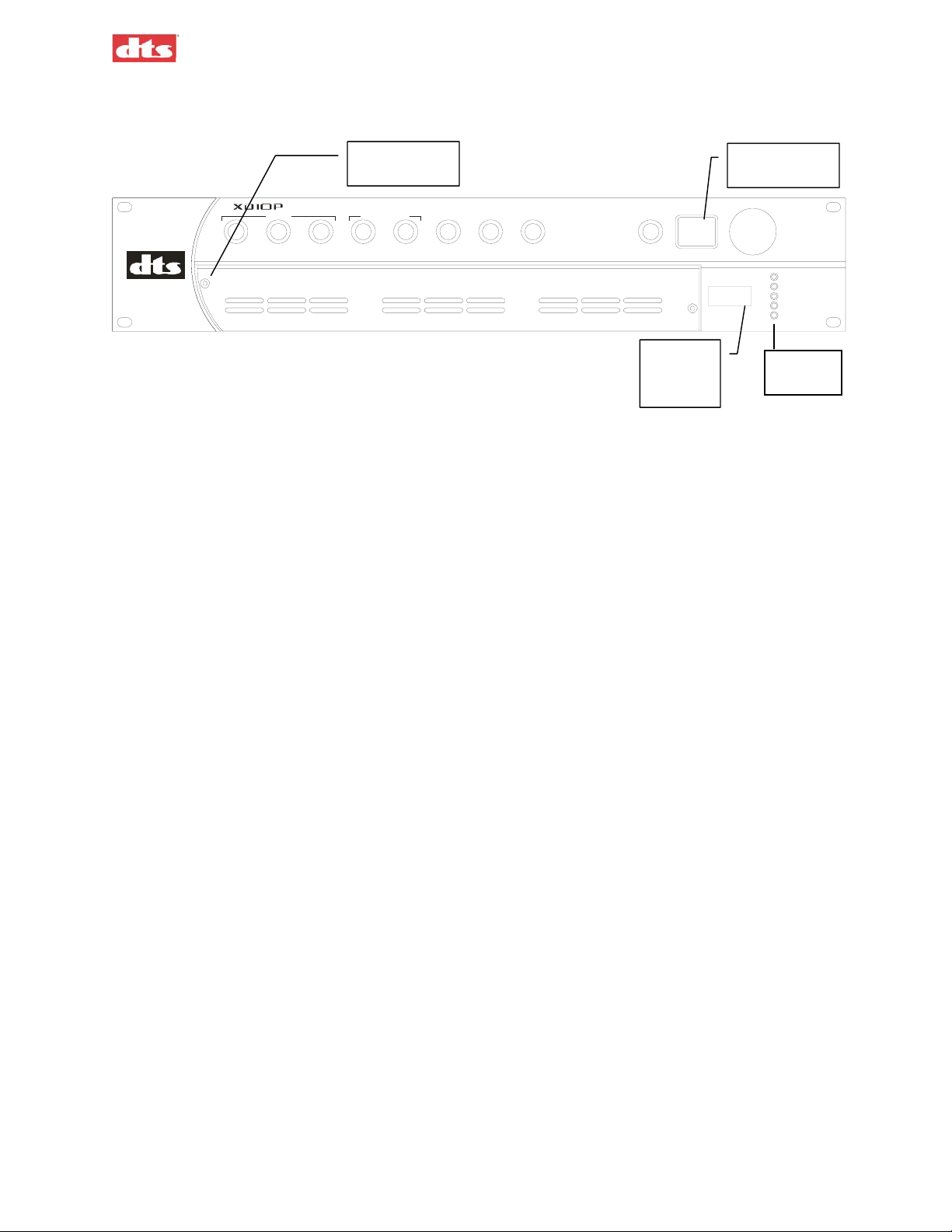
1.5. Front panel
XD10P Cinema Audio Processor, Installation and Operation Version 1.0
DTS
MONO STEREO
CINE MA AUDIO PR OCESSOR
OPTICAL 8 CHANNEL INPUTS
STEREO SR EX T 1 NON SYNC 1EXT 2 NON SYNC 2 MIC MUTE
Access panel
screw
1 of 2
(ANALOG) (D IGITAL)
Figure 1-1. XD10P Front Panel
Power
ON/OFF
BYPASS
Fader
Readout LED
MA IN FADER
+5V
+12V
-12V
AUX POWER
BYPASS
Power
LEDs
Front panel functions:
o Manually select formats and adjust the main fader.
o Numerical readout LED indicates fader level.
o Status LEDs indicate presence of power supplies.
o Turn off main power switch to place the unit into the bypass mode.
Each format has a preset level. During system setup, these presets can be set using a laptop computer
connected to the XD10P. (See chapter 3, Using XD10P Setup.) During normal operations, the presets
may be set directly on the front panel. See Changing a Format Level Preset, in chapter 2, Operations.
1. XD10P Overview Document #: 9301E855001.0
1-2
Page 16
XD10P Cinema Audio Processor, Installation and Operation Version 1.0
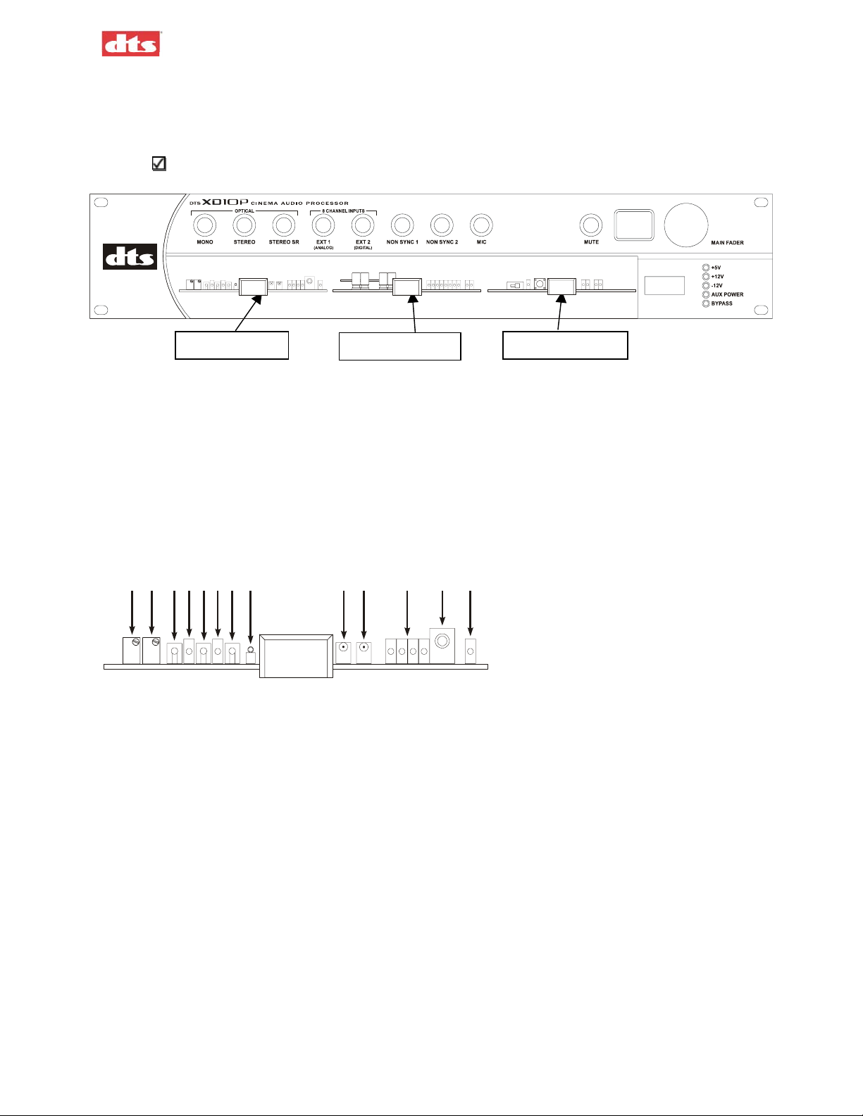
1.6. Modules
A removable panel allows access in order to service or replace internal modules. Two screws (left and
right) secure the panel in place.
Be careful to retain the panel and screws for re-installation.
Input module
Figure 1-2. Front access panel has been removed. Modules are visible.
Output module
Control module
1.6.1. Input Module
The Input Module contains the projector preamps plus non-sync and MIC inputs. It also contains the
bypass circuitry. Two high power DSPs implement A type and SR noise reduction. A third DSP is used
for the matrix decoder, slit EQ analyzer, and pink noise generator. Test points permit connection of an
oscilloscope to align the film projector’s analog reader. Level LEDs indicate the presence of left, center,
right and surround signals. Status LEDs indicate the module is “active” or in a “fault” condition.
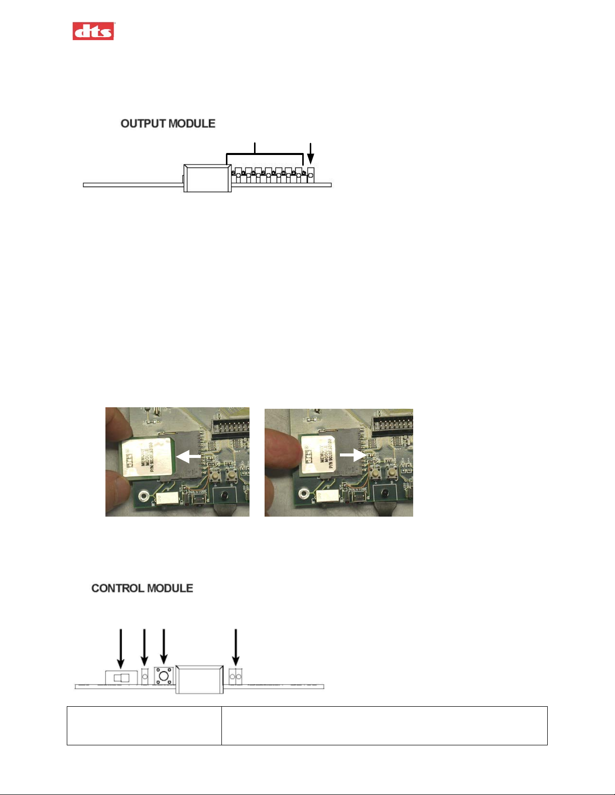
INPUT MODULE
7
1234
56
8
910 12
11
1. Projector 1 Bypass Level Adjust
2. Projector 2 Bypass Level Adjust
3. Left Channel Test Point
4. Projector 1 Indicator LED
5. Right Channel Test Point
6. Projector 2 Indicator LED
7. Ground Test Point
8. Bypass Level Test Point
9. Left Channel Level Indicator LED
10. Right Channel Level Indicator LED
11. Signal Presence LEDs, left to right: L, C, R, S
12. THX Pink Noise Enable Jack (see THX RT60 Reverberation Time Test, page 3-17)
13: Fault LED (DSP error)
13
1.6.2. Output Module
The Output EQ Module contains the eight-channel analog and AES-EBU input circuitry. It also contains
the balanced output circuitry. Two high power DSPs implement seven channels of 1/3 octave
equalization, plus a parametric subwoofer equalizer. Test points on each channel permit connection of
1. XD10P Overview Document #: 9301E855001.0
1-3
Page 17
XD10P Cinema Audio Processor, Installation and Operation Version 1.0
diagnostic instruments. Level LEDs indicate the presence of signals. A status LED indicates the module is
“active” or in a “fault” condition.
1
2
21
1. Immediately shown to the right of the pull handle in sequence are both Signal Present LED and Test
Points:
L, C, R, Sw, Ls, Rs, Lc, Rc
2. The last LED on the right is Fault (Lighted = DSP error).
1.6.3. Control Module
The Control Module manages all the communication in the unit. It also contains the automation interface,
bypass volume and remote volume circuitry. A removable memory module stores all settings.
The memory module is a smartcard that resides in a small slot on the Control Module. It can be ejected
and installed in a different XD10P to move the configuration information from one unit to another. But
normally the memory module should remain installed in the Control Module.
Figure 1-3. Removing and inserting memory module from Control Module.
To remove the memory module, grasp it gently and pull outward. To install it, gently press inward until it
stops firmly into place.
123
45
1. Write Protect Switch The installer sets this switch OFF (to the left) during setup. After all
site configuration settings have been finalized, and a back-up of all the
settings to the memory module has been invoked from the XD10P
1. XD10P Overview Document #: 9301E855001.0
1-4
Page 18
XD10P Cinema Audio Processor, Installation and Operation Version 1.0
Setup program, the installer must move the Write Protect switch to the
ON position (to the right), which write protects the memory module.
2. Write Protect Indicator LED When lighted, Write Protect is ON.
3. Default Restore Switch Press and hold the Restore Switch during system power up until
Restore LED begins to flash, to restore the unit's DSP Flash memory
with the settings obtained from the memory module. The memory
module is intended as a “fallback” restoration method, without need
for a laptop. The DSP Flash memory consists of 5 total ICs located
throughout the unit.
4. Status LEDs Left (Green) = Restore: when flashing, indicates the unit’s DSP Flash
memory is being restored.
Right (Red) = Loss of AES
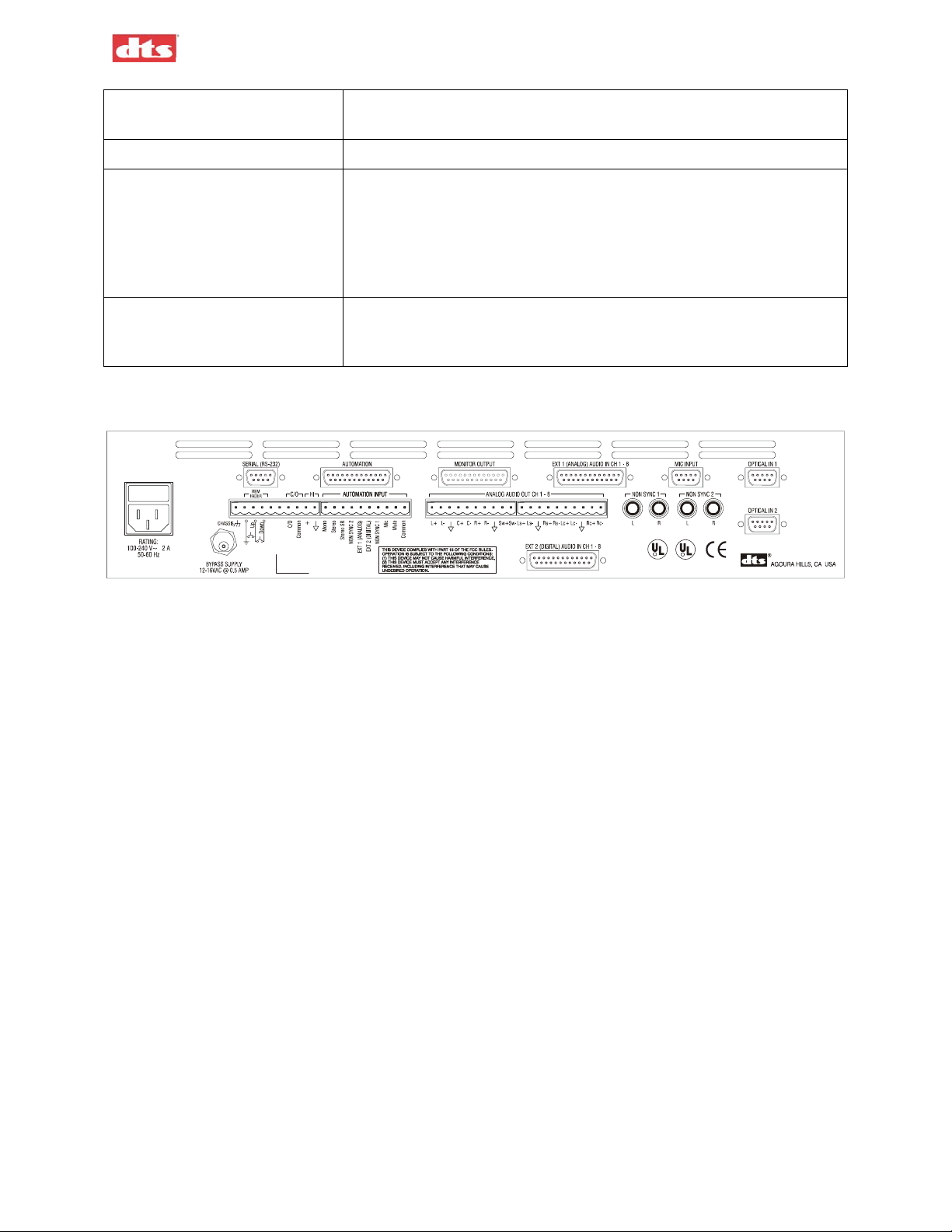
1.7. Rear Panel
R
R
PLACE E880
LABEL HERE
C
LISTED
NWGQ
"DTS" is a registered trademark of Digital Theater Systems, Inc
5TO7
Figure 1-4. Rear Panel, XD10P
1.8. Input Connectors
1.8.1. Projector Inputs
The projector inputs are connected through standard 9-pin D-type connectors. See Appendix A for
pinout data.
1.8.2. NON SYNC 1, NON SYNC 2 Inputs
Two sets of RCA connectors facilitate easy connection to standard CD players. A software fade in/fade
out algorithm (only in NON SYNC 1) allows smooth transition between intermission music and the main
program. See the wiring diagram, drawing F207 in Appendix B.
1.8.3. MIC Input
The public address balanced microphone inputs are available on a standard 9-pin D-type connector. See
Appendix A for pinout specifications. Also see the wiring diagram, drawing F207 in Appendix B.
The “Mic in +” and “Mic in -” terminals are for the balanced medium-low impedance microphone inputs.
The shield of the microphone cable should be connected to chassis ground on pin 5. A 9V power pin
allows easy connection of electret (powered) microphones.
.
1.8.4. EXT 1 (Analog) Input
The Analog input is eight-channel analog audio input from an analog source. The 25 pin D-type
connector is compatible with most decoders. Input level should be 300 mV RMS for all channels. See
Appendix A for connector pinout specifications.
For XD10 Analog 8-track OUT to XD10P Analog IN, see drawing F210 in Appendix B.
For DTS-6D Analog OUT to XD10P Analog IN, see drawing F204 in Appendix B.
1. XD10P Overview Document #: 9301E855001.0
1-5
Page 19
XD10P Cinema Audio Processor, Installation and Operation Version 1.0
1.8.5. EXT 2 (Digital) Input
The digital domain input is configured for eight channels (four differential AES3 PCM data pairs @ 48
kHz sample rate). See Appendix A for connector pinout specifications.
Any AES3 PCM channel format ID bits (such as Pro/Consumer, Pre-Emphasis, etc.) are ignored. Upon
any anomalies of the AES/EBU data stream, an emergency default mode has been implemented (see
Digital Link Default, page 4-15). Upon any occurrence of the loss of AES/EBU word clock, or “nonPCM data” being delivered, an instantaneous “soft mute” is performed and the unit will automatically
switch to the format chosen by the installer.
For XD10 Digital Audio OUT to XD10P Digital Audio IN, see drawing F206 in Appendix B.
1.9. Audio Signal Output Connections
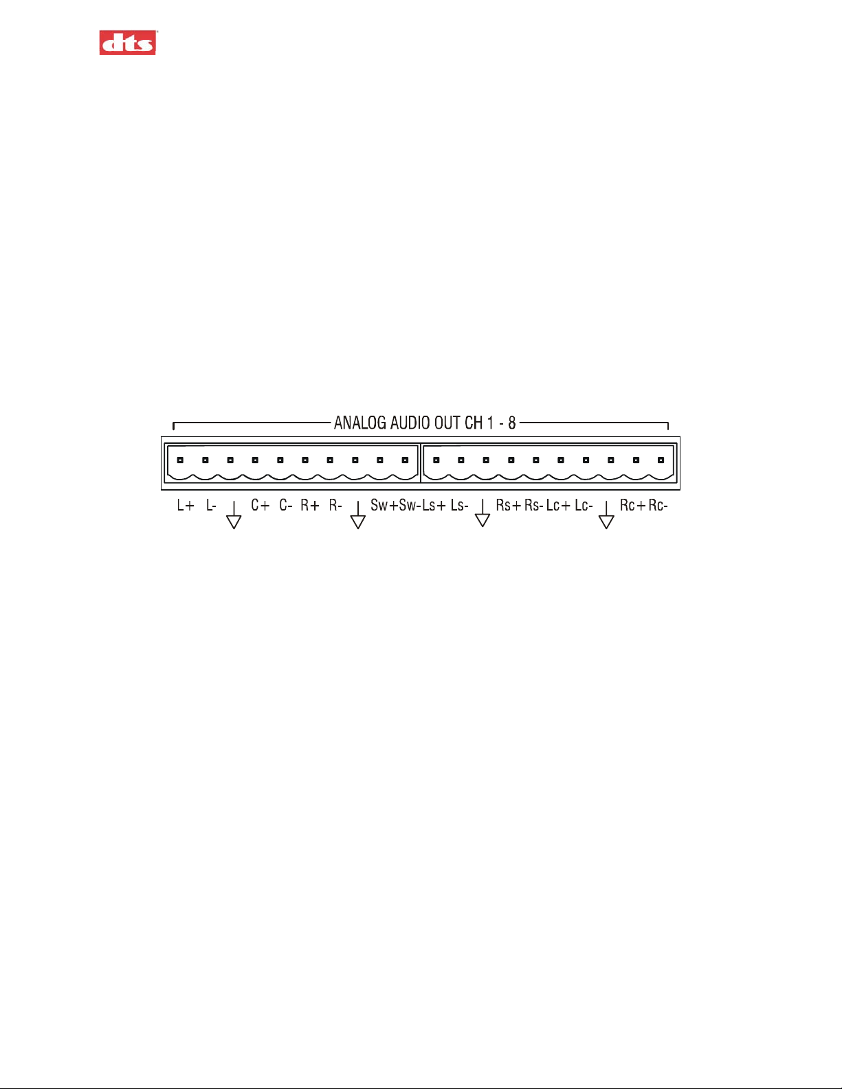
1.9.1. ANALOG AUDIO OUT CH 1-8
These are the main processor outputs to connect to the power amplifiers. The outputs are balanced, and all
have a corresponding ground terminal. Use two-conductor shielded cable for each channel. The shield
should usually be connected to ground at the power amplifier end only.
Figure 1-5. Analog Audio Out connector
See drawing F208 , “XD10P Analog Audio (Phoenix Connectors)” in Appendix B.
1.9.2. MONITOR Output
This is a 25 pin D-type connector containing the line output signals for all eight channels. These outputs
are in parallel with those of the Analog Audio Out connector (above). It can be connected directly to most
booth monitors. (See your booth monitor manual for connection details.) The Monitor Output connector
is also pin-compatible to THX-type systems. See Appendix A for the pinout specification for this
connector. See Appendix B, drawing F209, for an example of this connector used with a THX-type
system.
1.9.3. HI (Hearing Impaired) Output
This line level output is the sum of the left, center, and right channels. It can be connected to a hearing
impaired system. Output level is 300 mV RMS.
See drawing F205 “XD10P Logic, Hearing Impaired, External Inputs” in Appendix B.
1. XD10P Overview Document #: 9301E855001.0
1-6
Page 20
XD10P Cinema Audio Processor, Installation and Operation Version 1.0
1.10. Automation Connections
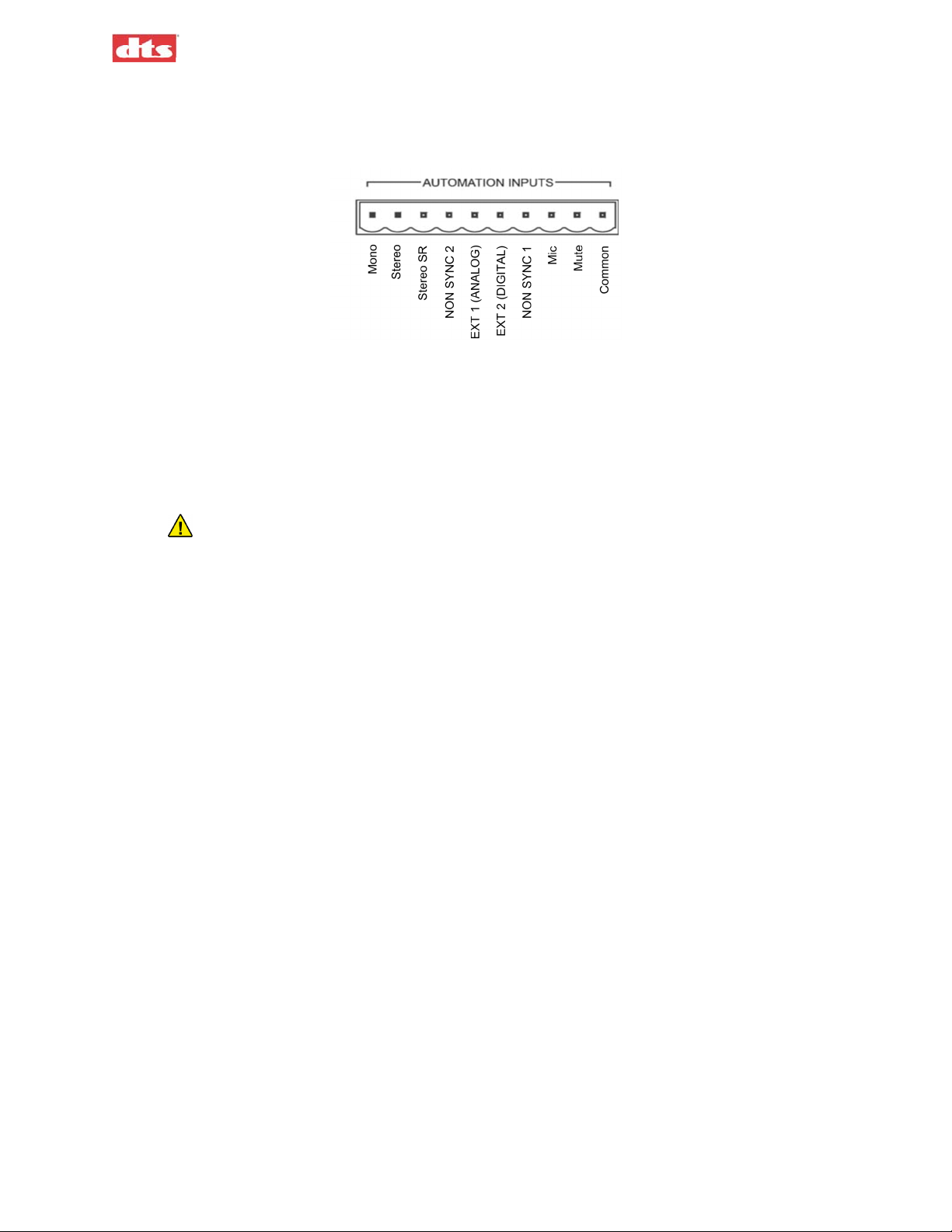
Figure 1-6. Automation Inputs
1.10.1. AUTOMATION INPUTS
These are contact closure inputs to remotely control the XD10P. There are automation inputs for each of
the eight XD10P operating modes, and a “Mute” input. These are intended to be momentary (or “pulsed”)
contact closures. The “Mute” function is released by selecting (or re-selecting) one of the main input
modes. The Automation common terminal is isolated from the system ground through a 10-ohm resistor
to minimize ground loop problems.
Do not connect circuit ground to chassis (earth) ground.
1.10.2. AUTOMATION
This 25 pin D-type connector contains most of the automation input and output signals. The pinout
specification for this connector is in Appendix A.
1.10.3. Automation LED Outputs
These are active-low outputs that can directly drive remote LEDs for monitoring the status of the XD10P.
The outputs are current limited, however an additional 1 kilohm resistor in series with each LED (at the
LED) is recommended in case of wiring faults. See the pinout specification for the Automation connector
in Appendix A.
1.11. Other Connections and Controls
1.11.1. Power Input
The XD10P uses an external 16 VAC @500mA power supply to power the bypass circuit.
1.11.2. REM FADER (Remote Fader)
The XD10P features a Remote Fader connection on the rear. The two-button remote fader device is not
supplied by DTS. (It can easily be obtained from any electronics supply store.)
Each tap on the UP button will increment 0.1 level. So starting at 7.0, one tap will increment to 7.1. A
tap on the DOWN button will decrement to 6.9. The Remote Fader level range is from 4 to 9. The front
panel will display the level increment/decrement as it occurs.
See the wiring diagrams in Appendix B for identification of the XD10P Remote Fader connection.
1.11.3. C/O (Changeover)
The XD10P includes dual preamplifiers for use in two projector changeover systems. Grounding the
“C/O” terminal mutes the Projector 1 input and selects Projector 2. This must be a maintained closure.
See the wiring diagram F205 in Appendix B for identification of the C/O connection.
1. XD10P Overview Document #: 9301E855001.0
1-7
Page 21

XD10P Cinema Audio Processor, Installation and Operation Version 1.0
1.11.4. RS-232 Port
A standard 9-pin D-type connector connects to a host PC computer, allowing you to control, configure,
and/or automate the XD10P via this interface. The cable should be a standard male to female serial-toUSB adapter, to interface with the USB port of a laptop computer.
The pinout information for the RS-232 serial port is in Appendix A. See wiring diagram F205 in
Appendix B for identification of the connection.
1. XD10P Overview Document #: 9301E855001.0
1-8
Page 22

XD10P Cinema Audio Processor, Installation and Operation Version 1.0
2. Operations
Caution: Do not make any changes to internal potentiometers (pots) or switches without the
guidance of DTS or your service technician.
2.1. Select Format
Normally, automation will be programmed to select format during the show. You may also manually
change formats via the front panel. Press the appropriate format button to select a format.
Available formats:
Mono
1
Stereo (A-type NR
Stereo SR (SR-type NR) Use this format only if the audio was recorded in SR. The analog
format should be marked on the print.
EXT1 analog
EXT2 digital
Non-Sync 1
Non-Sync 2
Mic
)
2.2. Adjust Fader
Set the level for the selected format by turning the Main Fader knob on the front panel. The LED display
on the front panel will indicate the change.
2.3. Changing a Format Level Preset
Format presets are set during the setup procedure using a computer. If you need to change the setting
during the show without a computer, press and hold the appropriate format button on the front panel for
two seconds and, while continuing to press it, rotate the main fader to the desired level. Then release the
button.
This will change the preset level for that format. No other format levels will change. The LED display
will indicate the preset level. Each format can be set for a different level, if necessary.
2.4. Operation in Bypass Mode
Bypass mode is triggered automatically in case the XD10P fails, or you can intentionally put the unit into
Bypass mode due to an audio emergency. You might do this if the sound in the auditorium has noticeable
defects, such as scratchy, garbled, or crackling sounds. The cause of the problem may not be apparent – it
may be a speaker problem or a processor problem.
The auxiliary power supply
mode by turning the front panel power switch off.
In Bypass mode, the audio will be providing basic optical mode – Left, Center, and Right (no Surrounds
or Subwoofer).
must be connected and working before you manually switch into Bypass
Aux power supply must be connected to XD10P.
1. Turn the Power switch OFF on the front panel.
2. The red Bypass indicator will flash.
1
NR = Noise Reduction
2. XD10P Operations Document #: 9301E855001.0
2-1
Page 23

XD10P Cinema Audio Processor, Installation and Operation Version 1.0
The Main Fader on the unit is active while the system is in Bypass mode, because Aux power
is available. However, there is no Main Fader display.
3. If needed, set the level using the Main Fader knob on the front of the XD10P.
As you turn it, the sound level gradually changes. Continue turning it until the sound level is
good. If you do not have success, contact your service technician.
2.5. Remote Fader
The remote fader function can be accomplished two ways, either through RS-232 commands or with a
simple pair of push buttons (see REM FADER on page 1-7). One button increases levels and the other
decreases levels. The LED display on the XD10P will indicate the change.
DTS does not provide a remote fader pushbutton device. But an RS-232 interface with a laptop computer
enables the XD10P Setup software to control the fader remotely. See the drawing F205 “XD10P Logic,
Hearing Impaired, External Inputs” in Appendix B.
2. XD10P Operations Document #: 9301E855001.0
2-2
Page 24
XD10P Cinema Audio Processor, Installation and Operation Version 1.0
3. Using XD10P Setup
3.1. Installing the Software
Begin by placing the XD10P Setup software CD into the CD-ROM drive of your computer. The
installation program should start automatically within a few seconds.
Note: If it does not start automatically, you will need to run “Setup.exe” from the root
directory of your CD-ROM drive. Either double click the “Setup.exe” icon or click the
Windows “Start” button and select “Run...”. Type “X:\setup.exe”(where X: is your CD-
ROM drive), then click the “OK” button.
Follow the instructions in the installation software.
Remove the CD-ROM when the software installation process is complete.
3.2. Starting the Program
A computer must be attached to the XD10P via the RS-232 port in order for the system setup to proceed.
A serial cable is used to connect the serial port of the computer to the XD10P RS-232 port, or a serial-toUSB adapter connects the USB port of the computer to the XD10P RS-232 port.
Note: When the computer is connected to the XD10P, the Setup software takes total control,
and the buttons and fader knob on the front panel of the XD10P will not respond to user
interaction.
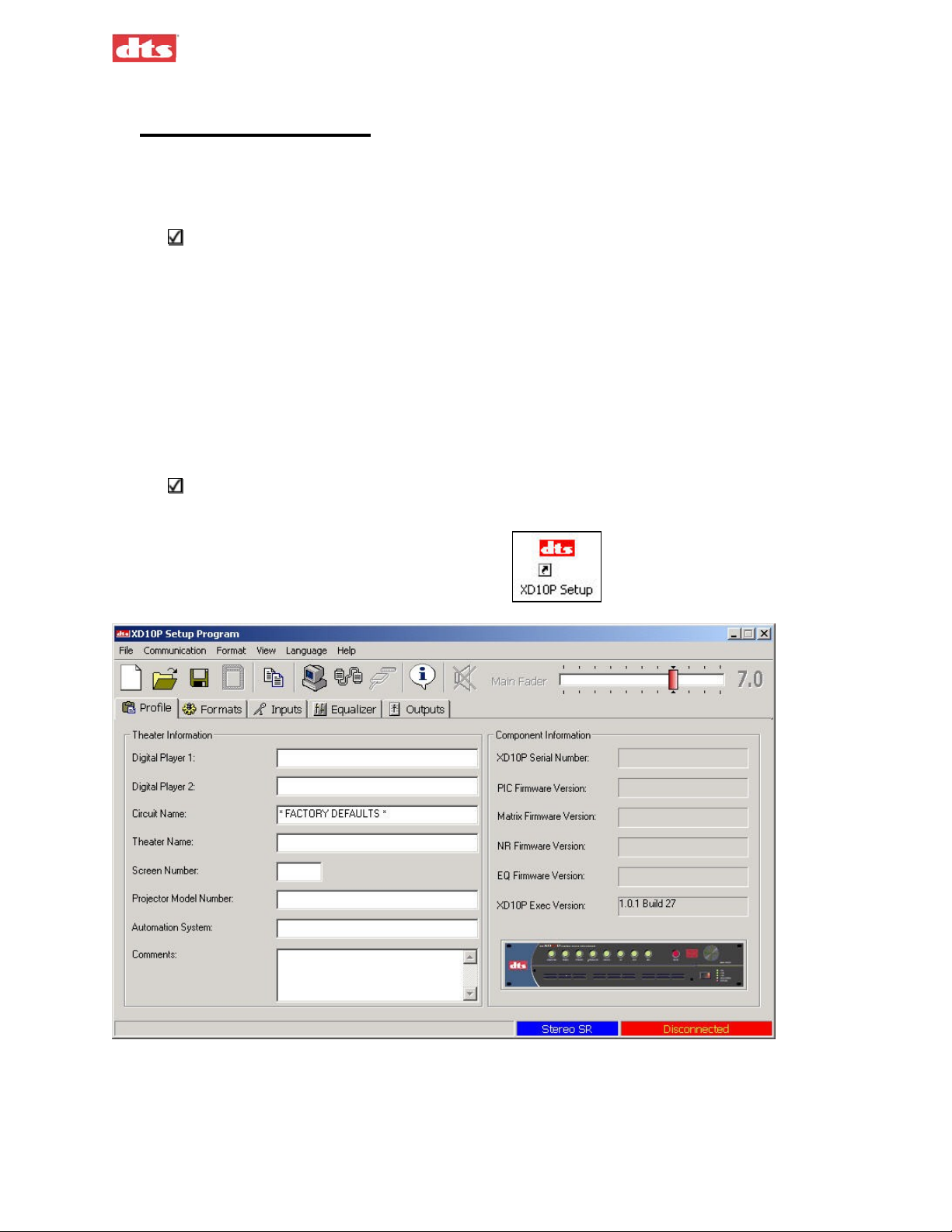
Click the XD10P Setup icon on the desktop.
The opening screen appears. (See page 4-1 for detailed
description of this screen.)
Figure 3-1. Initial screen, XD10P Software
If you are setting up the XD10P for the first time, you may want to fill in the particulars of the venue in
the “Theatre Information” boxes provided in the Profile tab. For details, see the description of the Profile
tab on page 4-6.
3. Using XD10P Setup Document #: 9301E855001.0
3-1
Page 25
XD10P Cinema Audio Processor, Installation and Operation Version 1.0
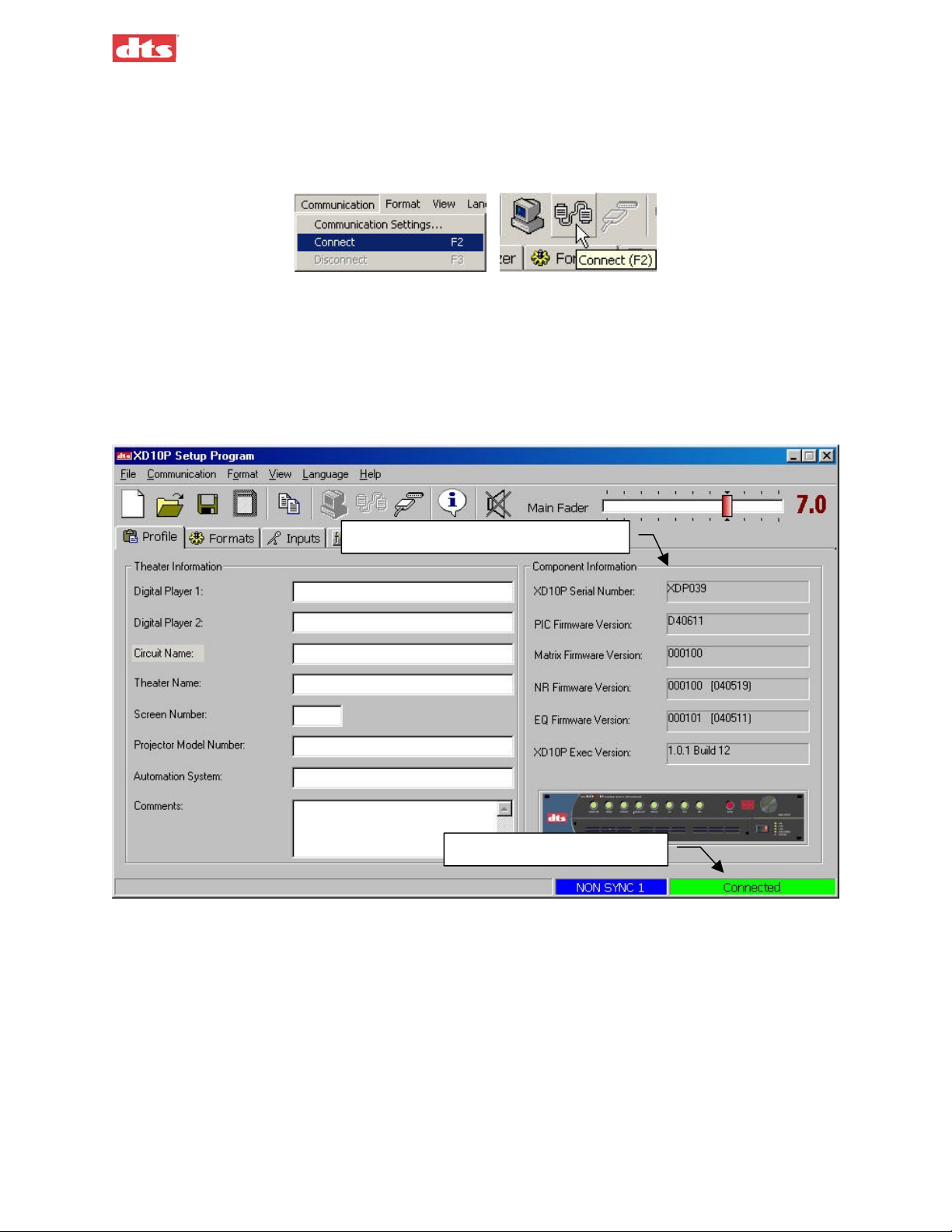
3.3. How to Connect
The next step is to establish communication with the XD10P. Press the F2 key or click the Connect icon
on the toolbar (or select Connect from the Communication menu) and the computer will connect with
the XD10P.
Figure 3-2. Select Connect from the Communication menu or click the Connect icon.
The connection status bar in the lower right hand corner of the main screen will change from
“Disconnected” to “Connected” (Figure 3-3).
When you connect to the XD10P, the computer will download all the data stored on the XD10P to the
computer’s memory. This data includes Preamp parameters, EQ parameters, Front Panel parameters and
Profile information. The Component Information display area of the initial screen will no longer be
empty; it will show serial number and version information.
Component Information is displayed
“Connected” status indicator
Figure 3-3. Profile tab after connecting to XD10P
3. Using XD10P Setup Document #: 9301E855001.0
3-2
Page 26
A
XD10P Cinema Audio Processor, Installation and Operation Version 1.0
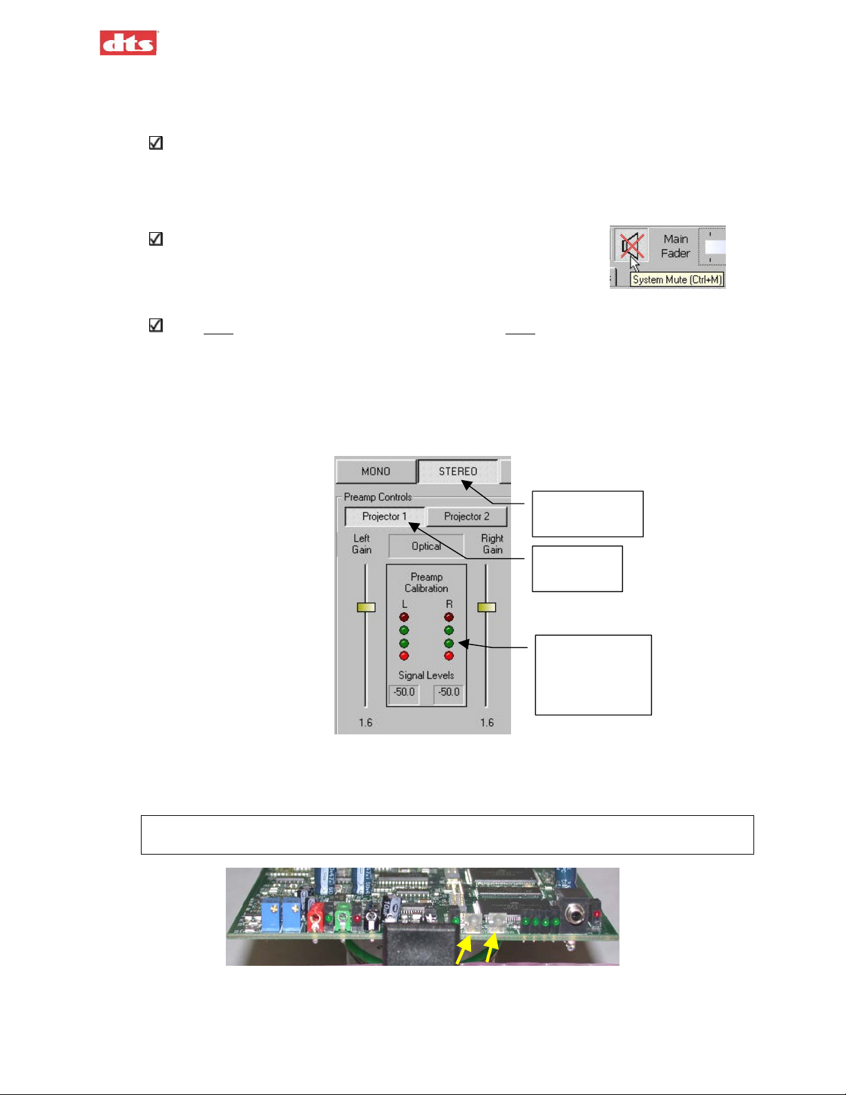
3.4. Preamp Calibration (A-Chain or Optical Setup)
This procedure calibrates the processor to the optics of the projector.
This procedure assumes that optical alignment of the projector has already been done. For
alignment of the projector optics (mechanical alignment of the head), see Appendix E.
Test Materials Required:
• 50% Modulation Tone test film
Before doing A-Chain calibration, be sure to mute all channels.
Click the Mute All Channels button at the top of the screen (or press
Ctrl+M keys).
1. Select the Inputs tab.
You must be connected to the XD10P and the XD10P must have a signal source connected to
either Projector 1 and/or Projector 2.
2. Select the appropriate Projector button (for the projector that is the source for the soundtrack
input.
3. Turn ON the projector (with the “50% Modulation Tone” film loop loaded).
4. Select an optical format: Stereo, or Stereo SR, from the Format buttons.
Select an
optical format
Select a
Projector
djust the Gain
sliders until all
4 green LEDs
are ON.
Figure 3-4. Preamp Controls on Inputs tab
5. Use the Left Gain or Right Gain slider to adjust the gain to align the left and right. (You can also
use the UP/DOWN arrow keys on the keyboard.)
All four green Preamp Calibration LEDs (shown above) should be lighted steady (not flickering).
The green LEDs on the Input module (shown below) should also be lighted green.
Figure 3-5. The two green LEDs will illuminate when level is correct.
3. Using XD10P Setup Document #: 9301E855001.0
3-3
Page 27
g
Q
XD10P Cinema Audio Processor, Installation and Operation Version 1.0
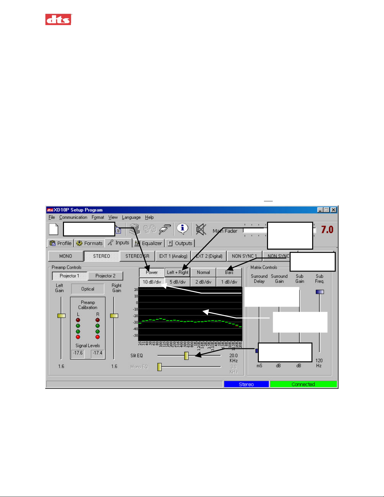
3.4.1. Slit EQ Adjustment
Test Materials Required:
• Pink noise test film
This procedure compensates for any deficiencies or imperfections that may be present in the mechanical
alignment (in the projector). Prior to this adjustment, the installer should have physically moved the
optical reader lens of the projector for the best focus and azimuth, which will result in better outcomes in
slit loss. See Appendix E.
Select the Inputs tab.
1. Confirm that all channels are muted.
2. Load the Pink Noise test film into the projector and start the projector.
3. Click the Power On button and a bar graph (or line graph) will display across the Analyzer
screen.
4. Select the Bars or Lines option button to select the type of graph to display on the spectrum
analyzer (SA).
5. Select Left and/or Right channel. (In this example, both Left Ch and Right Ch are selected.)
6. The interval for the Y-axis defaults to 10 dB/div. We recommend you
Power ON
Interval for Yaxis divisions
not change this.
Select Left
and/or Right
channel
Select Bars
or Lines
Double-click to
e
enlar
Move the Slit
E
slider
Figure 3-6. Inputs screen, showing bar graph on SA.
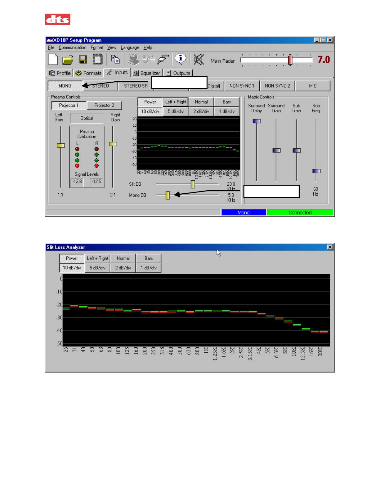
7. Double-click on the equalizer screen to enlarge it for a better view.
3. Using XD10P Setup Document #: 9301E855001.0
3-4
Page 28

XD10P Cinema Audio Processor, Installation and Operation Version 1.0
Figure 3-7. Slit Loss Analyzer, enlarged view (bar graph) showing relatively flat pattern.
8. Move the Slit EQ slider to adjust the equalizer until a response similar to that shown above
(Figure 3-7) is obtained – that is, the graph is relatively “flat” from left to right, without
significant upward or downward sloping on the right-hand end of the graph.
Note: Move the Slit EQ slider left or right and observe the effect on the graph in the Analyzer
window. Movement of the slider all the way to the right causes the graph to turn downwards
on the right end. Movement all the way to the left causes the graph to turn upwards on the
right end. Use the slider for large adjustments; use the UP/DOWN arrow keys for finetuning.
If the bars (or lines) in the graph are not overlaying each other after fine-tuning, check your
projector’s mechanical optical alignment. See Appendix E.
3.4.2. Mono EQ
Select the Inputs tab, and mute all channels.
1. Select the Mono format.
2. Thread a Pink Noise film loop into the projector and turn ON the projector.
3. Using XD10P Setup Document #: 9301E855001.0
3-5
Page 29
XD10P Cinema Audio Processor, Installation and Operation Version 1.0
Select MONO
Mono EQ slider
Figure 3-8. Input tab, Mono EQ adjustment
3. Using the Mono EQ analyzer adjust the MONO EQ until the following curve is achieved.
Figure 3-9. SA screen during Mono EQ adjustment
The curve shown, plus the auditorium roll-off, approximately equals the standard Academy
Curve.
A-Chain Alignment is now complete.
3. Using XD10P Setup Document #: 9301E855001.0
3-6
Page 30

XD10P Cinema Audio Processor, Installation and Operation Version 1.0
3.5. B Chain Alignment
Left, Left Center, Center, Right Center, Right, Left Surround, Right Surround
You will be adjusting the alignment of each individual channel. There are various approaches to B-chain
alignment, and the procedure presented below is offered as an example, not a requirement. The intent is
to show the XD10P functions that are relevant to B-chain alignment.
Equipment Required:
• Real Time Analyzer (RTA) with microphone (see the topic Built-in RTA Function,
page 3-17.
• (optional) multiple microphone system
• SPL meter
Caution: Before proceeding with the room equalization it is imperative that the loudspeaker
and crossover systems be properly aligned. Issues like speaker phasing and horn tilt need to
be checked. When using crossovers the low, mid and high frequency drivers must be
balanced to produce a relatively even response from 100 Hz to 5 Hz.
Figure 3-10. Suggested Microphone placement in theatre
3. Using XD10P Setup Document #: 9301E855001.0
3-7
Page 31

XD10P Cinema Audio Processor, Installation and Operation Version 1.0
Note: With a bi-amp system, during the B-chain adjustment you would adjust the amps or the
crossover for flattest response on the RTA and make sure the setting is the same for all screen
speakers. After the adjustment is complete, proceed with normal EQ adjustments with the
XD10P Setup software, as described in the steps that follow.
1. Set up a Real Time Analyzer (RTA) with the microphone two-thirds (2/3) of the way back and
one-third (1/3) of the way in from the side of the auditorium (that is, slightly off-center).
Note: Be sure to open the curtains (if any) at the front of the auditorium.
If using a multiple microphone system set up the microphones according to the instructions
provided with that system.
In the XD10P Setup software, set the Main
2.
Fader to “7.0”. Verify on the XD10P front
panel, that the fader setting matches (7.0).
3. Select the Equalizer tab and choose a
channel. The screen channels (L, LC, C, RC, R) are always done before the surround channels.
In this example – Figure 3-11 – we begin with the center channel.
4. Using the Channel Gain slider, adjust to –16 dB (recommended), to avoid damaging the
speakers.
5. Select Pink Noise.
Channel Gain slider set to –16.0
Bass slider
Select Stereo
Select a channel
Treble slider
Figure 3-11. Equalizer tab
Note: Muted channels are highlighted in RED in the Equalizer Tab.
6. Raise the Channel Gain slider slowly until proper level is reached on RTA.
7. Using the RTA, observe the curve and make adjustments.
8. Use the Bass and Treble sliders to make overall adjustments.
3. Using XD10P Setup Document #: 9301E855001.0
3-8
Page 32

XD10P Cinema Audio Processor, Installation and Operation Version 1.0
The goal is to achieve a 3 dB roll off at 2 kHz, on every channel except Subwoofer, as shown in
this example. (Subwoofer equalization is detailed in B Chain Alignment - Subwoofer
Equalization, page 3-10.)
Figure 3-12. RTA example. Try to obtain this pattern for ALL channels except Subwoofer.
9. Use the individual sliders for fine-tuning.
Note: Once a slider is selected with a mouse click, the keyboard UP/DOWN keys will adjust
the slider. The left/right keys will switch to the adjacent 1/3 octave slider. Use the Bass and
Treble sliders to achieve the overall shape of the auditorium response. After making the EQ
adjustments, it may be necessary to fine-tune the level setting (in the Outputs tab).
10. Repeat the tuning procedure (steps 4 through 9) for the left, right, left center, right center and
surround channels. You may use the Copy feature to simplify this procedure (see next topic).
3.5.1. Use the Copy Feature
The XD10P includes a Copy feature that minimizes the time required for re-equalizing similar
channels (see Figure 3-13, below).
After equalizing the center channel, copy these settings to the left, left center, right center, and
right channels. Since all three front speakers are usually similar, if not identical, the EQ settings
will be a close starting point. Similarly, after equalizing the left surround, copy these settings to
the right surround channel.
To access Copy, select Copy from the File menu, click the Copy EQ icon in the toolbar,
or press key combination Ctrl+Shift+C.
Figure 3-13. Copy EQ settings
• Select the Copy From channel, then select the Copy To channel, then click the Copy>>
button.
3. Using XD10P Setup Document #: 9301E855001.0
3-9
Page 33

XD10P Cinema Audio Processor, Installation and Operation Version 1.0
3.6. B Chain Alignment - Subwoofer Equalization
Equipment Required:
• Real Time Analyzer (RTA) with microphone
• (optional) multiple microphone system
• SPL meter
1. Verify Subwoofer amplifier is OFF and level control of amp is at minimum.
2. Select the Equalizer tab and select Subwoofer in the Channel array.
Select Subwoofer
Figure 3-14. Equalizer tab, Subwoofer selected
3. In Sub Bass Parametric Equalizer section, adjust Gain slider to top 0.0, adjust Q to midpoint or
5.25, and adjust Frequency to 120 Hz.
4. Power ON the Subwoofer amp. Raise gain on amp until sub frequency response is seen on the
RTA.
5. Note the highest peak on the RTA. Move the Frequency slider until center of dip is at the highest
peak frequency.
6. Adjust Gain slider to flatten the dip.
7. Adjust Q slider to flatten overall response.
The subwoofer should fill in the lowest frequencies and create a smooth overall response on the
RTA from 25Hz to 1 KHz.
3. Using XD10P Setup Document #: 9301E855001.0
3-10
Page 34

XD10P Cinema Audio Processor, Installation and Operation Version 1.0
Figure 3-15. The expected pattern on the RTA
when the subwoofer pink noise is playing in the theatre.
It may be necessary to adjust the subwoofer channel gain. It may also be necessary to click to
phase invert on the subwoofer to be sure that the low frequencies of the center and subwoofer are
adding, rather than subtracting.
3.7. Final Adjustments, B-Chain
Adjust all the levels to the proper setting, using the SPL meter. (If equipped with ES – Extended
Surround – please refer to the ES manual for instructions to adjust channels.)
In the Outputs tab:
• Set levels for “screen channels” L, LC, C, RC, R at 85 dBC with an SPL meter.
• Set levels for surround channels LS, RS at 82 dBC with an SPL meter.
• Digital Subwoofer gain setting (from XD10 digital out or other digital source) – The digital
Sub must be set for +10dB in-band gain as compared to the Center channel. See Digital
Subwoofer Gain Setting, below.
In the Inputs tab:
• Optical (analog) surround and sub level (see Optical Surround Gain and Delay on page 3-12
and Subwoofer Optical Gain on page 3-13).
3.7.1. Digital Subwoofer Gain Setting
1. Select Outputs tab.
2. Select Pink Noise Center channel, adjust to 85 dBC, and note average frequency response level.
3. Select Pink Noise Subwoofer, adjust level 10 dBC (in-band gain) more than the average
frequency level noted above for the Center channel.
3.7.2. Bypass Level (B-Chain) Calibration
Calibrating the Bypass Level is to be performed by a technician, not by an operator.
Note: Aux power supply must be connected to XD10P for bypass to work.
The Bypass Level setting adjusts the sound level in case the XD10P fails or is intentionally put into
bypass mode. The operator can put the XD10P into bypass mode and can adjust the sound level using the
Main Fader (see page 2-1) but should NOT attempt to
3. Using XD10P Setup Document #: 9301E855001.0
calibrate the bypass level.
3-11
Page 35

XD10P Cinema Audio Processor, Installation and Operation Version 1.0
Equipment Required:
• SPL meter
• Aux power supply (connected to XD10P)
Alignment Procedure:
1. Run an optical Pink Noise source (film) on the projector.
2. Set the Main Fader on XD10P to 7.0.
3. Place SPL meter in auditorium. Note the auditorium reading (for example, 85 dB) and record it.
4. Turn the Power switch OFF on the XD10P. This switches the unit to bypass mode and the
Bypass indicator will flash.
5. Read the new level on the SPL. For example, it might be up to 90 dB. It needs to be adjusted to
about 3 dB lower than the level recorded in step 3, above.
6. If necessary, adjust the trim pots on the Input module (Figure 3-16, below) for an SPL level that
is 3 dB lower than the level that was noted when the power switch was ON (step 3, above). For
example, turn Projector 1 potentiometer (on the left) to 82.
You will need to remove the front access panel to gain access to the Input module, which is on
the left side.
Do not rotate the Main Fader knob at this time or the bypass level will change.
INPUT MODULE
1234
56
7
8
910 12
11
13
Figure 3-16. Input module, Bypass Level trim pots (1 and 2)
1. Projector 1 Bypass Level Adjust
2. Projector 2 Bypass Level Adjust
This completes the calibration of the bypass level.
Note: When in bypass mode, the operator can change the bypass level by adjusting the Main
Fader. However, the Main Fader knob must be rotated many more turns, compared to nonbypass mode, to achieve changes in level.
3.7.3. Optical Surround Gain and Delay
Depending on the size of the auditorium, there may be a delay between the screen channels and the
surround channels, to avoid an echo effect. This delay is to ensure that the sound from the back of the
theatre arrives at the listener’s ears approximately 20 milliseconds after the arrival of the front speaker
sound.
1. Calculate the surround delay by using the following formula:
a. Measure the distance from a selected rear seat to the nearest surround speaker (in feet). If
you are calculating in meters, multiply by 3 (m X 3) to convert to feet.
b. Measure the distance from the same rear seat to the nearest screen speaker (in feet).
c. Subtract the two measurements to find the difference, then add 20 to that number. The result
is the Surround Delay in milliseconds (mS).
3. Using XD10P Setup Document #: 9301E855001.0
3-12
Page 36

XD10P Cinema Audio Processor, Installation and Operation Version 1.0
d. In the Inputs tab, set the Surround Delay control accordingly.
Figure 3-17. Matrix Controls (on Inputs tab)
Example: Rear seat is 12 feet from nearest surround speaker.
Rear seat is 82 feet from nearest screen speaker.
The surround delay is set to 82-12+20 = 90 mS.
2. Using an RTA or SPL meter, adjust the Surround Gain in the Matrix Controls so that the
pressure level in the back matches the pressure level in the front.
3.7.4. Subwoofer Optical Gain
Equipment Required:
• RTA
• Pink Noise test film
1. Thread the Pink Noise test film into projector.
2. Turn
3. Select the Inputs tab and start projector.
4. Note average frequency response level on RTA display and the lower frequency roll-off.
5. Turn
6. Adjust Sub Gain under Matrix Controls in the Inputs tab, to match the same level of frequency
7. Turn
off Subwoofer amplifier.
off Center channel amplifier and turn on Subwoofer amplifier.
response. Adjust Sub Freq to match the roll-off of Center channel (noted in step 4).
on Center channel amp. Make any final adjustments so that Sub response is flat matching
average of Center channel response.
3. Using XD10P Setup Document #: 9301E855001.0
3-13
Page 37

XD10P Cinema Audio Processor, Installation and Operation Version 1.0
3.7.5. NON SYNC 1, NON SYNC 2, MIC Levels
Note: The operator can adjust these levels if the sound level is not right, using the controls on
the XD10P front panel. See Changing a Format Level Preset in chapter 2, page 2-1.
NON SYNC1
1. Connect the sound source to the NON SYNC 1 “L” and “R” RCA jacks.
2. Select the Inputs tab. Select the NON SYNC 1 format. The non-sync gain on the Preamp
Controls panel becomes active.
Figure 3-18. NON SYNC 1 adjustment (Preamp Controls)
3. Adjust the Left Gain slide pot. The master fader should be set at 7.0.
4. In the theatre, listen to the non-sync 1 audio, and then adjust the gain to a comfortable level.
NON SYNC2
1. Connect the sound source to the NON SYNC 2 “L” and “R” RCA jacks.
2. Click on the Inputs tab. Select the NON SYNC 2 format. Use the Left Gain slider to set the
NON SYNC 2 level.
Figure 3-19. NON SYNC 2 adjustment (Preamp Controls)
Note: In this format the two sliders move together.
3. In the theatre, listen to the non-sync 2 audio, and then adjust the gain to a comfortable level.
3. Using XD10P Setup Document #: 9301E855001.0
3-14
Page 38

XD10P Cinema Audio Processor, Installation and Operation Version 1.0
MIC
1. Connect a microphone to the DB9 connector (pins 1+ and 2- with shield on 5). If the microphone
is an electret type that requires 5 to 9 Volts DC you may use pin 7 on the DB9 for that power (see
Appendix A for pinout specifications).
2. Click on the Inputs tab and select the MIC format. Use the Left Gain slider to set the MIC level.
Figure 3-20. MIC adjustment (Preamp Controls)
3. In the theatre, listen to the mic audio, and then adjust the gain to a comfortable level.
3.7.6. Preset Levels and Startup Mode
1. Select the Formats tab and then choose a format.
2. Adjust the format level on this screen to an appropriate setting.
Note: The main fader moves as you adjust this.
3. Using XD10P Setup Document #: 9301E855001.0
3-15
Page 39

XD10P Cinema Audio Processor, Installation and Operation Version 1.0
Select a format
Select a default
startup format
Adjust level
Figure 3-21. Formats tab, EXT 2 selected
3. Select the default startup format (Power On Format) from the list shown.
Examples:
Selecting NON SYNC will cause the XD10P to start in non sync every time it is powered.
Selecting Last Selected will cause the XD10P to resume its last format before it was powered
down.
4. For EXT 2 (Digital) format, select the Digital Link Default format, in case there is a failure of
the digital link. For more information, see page 4-15.
Operator can adjust presets
The operator can change the setting during the show (without a computer), if necessary. Press and hold
the appropriate format button on the front panel for two seconds and, while continuing to press it, rotate
the main fader to the desired level. Then release the button.
This will change the preset level for that format. No other format levels will change. The LED display
will indicate the preset level. Each format can be set for a different level, if necessary.
3.7.7. Listening Test
Equipment Required:
• Buzz and Bill Show test film (DTS PN 6800000100)
• For digital sound testing, connect to an XD10 and play its built-in Buzz and Bill soundtrack.
1. After adjusting the EQ and SPL, play the Buzz and Bill Show test film.
2. Walk through the auditorium and listen to the sound quality from the speakers at different
locations. Be sure to listen in both optical and digital sound formats.
Press the EXT 2 Digital button on the front panel, to switch to digital format. Press the Mono,
Stereo, or Stereo SR button to switch to an optical format.
3. Using XD10P Setup Document #: 9301E855001.0
3-16
Page 40

XD10P Cinema Audio Processor, Installation and Operation Version 1.0
3. Verify there is uniformly good sound quality throughout the auditorium. If there are large
differences from one area to another, the EQ and SPL process should be repeated.
3.8. THX RT60 Reverberation Time Test
RT60 (Reverberation Time) is the test name for the measurement of the reverberation within a room. It is
defined as the time required (in seconds) for an average sound pressure level to decrease 60 decibels after
the source stops generating in a room. This and other tests are required for THX certification of a theatre.
Located on the XD10P Input module is a THX Pink Noise Enable jack that is used to perform RT60 and
other tests.
To execute tests, you must have the XD10P software running and connected.
1. Select Outputs tab.
2. Press and hold the Ctrl key on your laptop and select the pink noise box of each channel.
3. Once all boxes are selected connect your test equipment to the THX pink noise trigger jack on the
Input module of the XD10P.
Your test equipment will now activate all channels with pink noise during the test.
For further information refer to your test equipment instructions.
3.9. Built-in RTA Function
The XD10P Setup software features a built-in RTA function. However, the XD10P is not supplied with a
calibrated microphone, so DTS recommends that this built-in RTA only be used for quick checks. Initial
setup and adjustment should use a fully calibrated external RTA device.
Place a microphone in the auditorium and connect to the MIC IN connector on the XD10P. In the Setup
software, click the Inputs tab and double-click on the Slit EQ. It becomes a real-time analyzer (RTA).
3. Using XD10P Setup Document #: 9301E855001.0
3-17
Page 41

XD10P Cinema Audio Processor, Installation and Operation Version 1.0
3. Using XD10P Setup Document #: 9301E855001.0
3-18
Page 42

XD10P Cinema Audio Processor, Installation and Operation Version 1.0
4. Software Description
This chapter presents descriptive information about the XD10P Setup program screens. Detailed field
definitions are included. However, for instructions to install XD10P Setup program and for using the
program, see chapter 3.
Note: When the computer is connected to the XD10P unit, then the Setup software takes total
control, and the buttons and fader knob on the front panel of the unit will not respond to user
interaction.
4.1. The Opening Screen
Activate the XD10P Setup icon on the desktop.
The opening screen appears.
Main Fader
Tabs
Component
Information display
Theater Information area
Format and connection status indicators
Figure 4-1. Initial screen, XD10P Software
The opening screen has a Menu Bar, Toolbar, tabs for accessing software functions and, on the Profile
tab, a Theater Information entry area. There is also a Main Fader slider control, a Component
Information display area, and two indicators for Format and Connection status. These features will be
described in the paragraphs that follow.
4.1.1. Menu Bar
The menu bar gives access to various functions. These functions are duplicated on the Toolbar and
through keyboard hot-key combinations.
Figure 4-2. Menu bar
4. Software Description Document #: 9301E855001.0
4-1
Page 43

XD10P Cinema Audio Processor, Installation and Operation Version 1.0
File Menu
The standard Windows functionality for New, Open, Save, Save
As, and Exit are found in the XD10P File menu. In addition, there
are these unique functions:
Save to Personality Module – Save the current unit configuration to
the Personality (or Memory) module. See description of the
Control Module, page 1-4.
Copy EQ Settings – (See 3.5.1 Use the Copy Feature, page 3-9.)
System Mute – Toggle to mute or Unmute all output channels.
Communication Menu
The Comm menu functions are available from the toolbar, as well.
Communication Settings – Make changes to the serial communication
parameters. When selected, a dialog box will display.
Figure 4-5. Configure
Communications dialog
Select from the pull-down list of COM ports. This will be the communications port (of the
computer) used for communicating with the XD10P.
Connect – Establish a connection with a XD10P unit.
Disconnect – Disconnect from the XD10P unit.
Figure 4-3. File menu
Figure 4-4.
Communication menu
4. Software Description Document #: 9301E855001.0
4-2
Page 44

XD10P Cinema Audio Processor, Installation and Operation Version 1.0
Format Menu
The Format menu selections are duplicated in the Format tab. See Formats Tab, page 4-14.
Figure 4-6. Format menu
View Menu
The View menu duplicates the functionality of the tabs. See Tabs, page 4-4.
Figure 4-7. View menu
Language Menu
The Language menu allows you to choose the language of the XD10P Setup interface. The default setting
is your user language (your log-on setting) or the system language, but you can
change the language by selecting from this list.
Reset – This resets to the system default. The software reads your user-selected
language, looks for it and, if not found, then looks for your system language and, if
that is also not found, it defaults to English.
Figure 4-8.
Language menu
Help Menu
From the Help menu, select About to display version information for the XD10P Setup program. The
Unlock Diagnostics selection permits privileged access to diagnostic features (using a password).
Figure 4-9. Help menu
The diagnostic features are intended for use only by a trained technician. After entering the password,
three tabs will display: a Terminal tab for issuing commands for direct interface with the XD10P; a Log
Files tab for viewing log entries; and a PIC Download tab for loading new Programmable Interface
Controller firmware to the XD10P.
4. Software Description Document #: 9301E855001.0
4-3
Page 45

XD10P Cinema Audio Processor, Installation and Operation Version 1.0
4.1.2. Toolbar
The toolbar consists of graphic icons that give access to various functions. Placing the cursor over any of
the icons for a few moments will display a “tool tip” describing the function of the icon.
Figure 4-10. Toolbar
New – create a new parameter file
Open (an existing parameter file)
Save (the parameter file)
Save Personality Module – save the current
unit configuration to the Personality Module
Copy EQ – copy settings from channel to
channel (See 3.5.1 Use the Copy Feature,
page 3-9.)
Communication Settings – make changes to
the serial communication parameters
Connect – establish a connection with a
XD10P unit
Disconnect (from the XD10P unit)
About – displays program information and
how to contact Technical Support
Mute – or unmute all output channels
4.1.3. Tabs
(See Figure 4-1, page 4-1) Below the toolbar are tabs for accessing various operational modes. These tabs
will be described in order (left to right), beginning with the Profile tab on page 4-6.
4.1.4. Main Fader
(See Figure 4-1, page 4-1) The slider at the upper right is the main level control for the XD10P. It works
in conjunction with the fader knob on the front panel of the unit and will follow it, just as the level
indicator on the front panel will follow any movement of this fader control.
The level may be changed from the main screen by placing the cursor over the slider, holding down the
left button on the mouse, and moving the mouse left or right.
4.2. After Connecting to the XD10P
Note: When the computer is connected to the XD10P (see Figure 4-11) the Setup software
takes total control, and the buttons and fader knob on the front panel of the unit will not
respond to user interaction.
After the computer establishes connection to the XD10P, the connection status bar in the lower right hand
corner of the main screen will change from “Disconnected” to “Connected” (Figure 4-11).
4. Software Description Document #: 9301E855001.0
4-4
Page 46

XD10P Cinema Audio Processor, Installation and Operation Version 1.0
When you connect to the XD10P, the computer will download all the data stored on the XD10P to the
computer’s memory. This data can consist of Preamp parameters, EQ parameters, Front Panel parameters
and Profile information. The Component Information display area of the initial screen will no longer be
empty; it will show serial number and version information.
Note: The serial number and version information are important when contacting DTS
Customer Service.
Mute All Channels button
Component Information is displayed
“Connected” status indicator
Figure 4-11. Initial screen (Profile tab) after connecting to XD10P.
4. Software Description Document #: 9301E855001.0
4-5
Page 47

XD10P Cinema Audio Processor, Installation and Operation Version 1.0
4.3. Profile Tab
On the Profile tab, in the Theater Information area, there are several fields for entering information about
the
projection room configuration.
Figure 4-12. Theater Information area, Profile tab
This information is stored in the XD10P and can also be stored as a file on the computer you use to set up
the unit.
Note: You can enter this information at any time, whether connected to the XD10P or not,
and you can save it to disk for later loading onto the XD10P.
This information is
technician performing repair and realignment or in case factory repair is needed.
You may fill in these fields in Theater Information:
Digital Player 1 – what digital system is connected to the XD10P? Examples: DTS XD10, SDDS,
Dolby Digital.
Digital Player 2 – identify a second digital system, if any.
Circuit Name – enter the theatre circuit or company name
Theater Name – enter the name of this theatre
Screen Number –
Projector Model Number –
Automation System – Manufacturer and model number
not used by any functions of the unit but can be extremely valuable to a
Comments – add any additional descriptive comments
The Component Information fields are read from the XD10P and
cannot be changed by the user. At the
bottom right of the screen is the connection status bar and the format status bar (look back at Figure 4-11).
These will display in all tab views. The format status bar will always indicate the format that the processor is currently operating.
4. Software Description Document #: 9301E855001.0
4-6
Page 48

XD10P Cinema Audio Processor, Installation and Operation Version 1.0
4.4. Inputs Tab
The Inputs tab is used for A-Chain setup. (See Preamp Calibration (A-Chain or Optical Setup),
page 3-3.)
There are two sections to the Inputs tab. On the left, Preamp Controls is where the alignment is
accomplished for the optical preamp and it is vital for accurate optical performance. It contains buttons to
select either Projector 1 or 2, level settings for the Left and Right preamps (with accompanying level
indicators), Slit EQ and Mono EQ sliders and the spectrum analyzer (SA) screen.
The spectrum analyzer has annotations on the bottom and left side and option buttons at the top.
You must be connected to the XD10P and it must have a signal source from Projector 1
and/or Projector 2 before it can become functional. You
Stereo or Stereo SR. The projector must be running and connected to the optical input on the
XD10P.
On the right, Matrix Controls is used for setting surround delay and gain, subwoofer gain and frequency
and non-sync gain. (See Matrix Controls, page 4-11.)
How to adjust levels (using sliders)
To adjust a level, place the cursor over the desired slider’s button and hold down
the left mouse button while moving the mouse.
must also choose an Optical format:
The sliders (once they are selected) may also be manipulated by using the UP or
DOWN arrow keys on the keyboard. The LEFT/RIGHT arrow keys will select the
sliders to the left or right of the one initially chosen. At the bottom of the slider is a
box that displays numerically
in dB the position of the slider.
The figure below shows the Inputs screen when the connection is active to the XD10P.
Formats
Choose a projector (the signal source)
Spectrum Analyzer
Preamp Calibration indicators and sliders
Figure 4-13. Inputs tab, connection is active (1 of 2)
4. Software Description Document #: 9301E855001.0
4-7
Page 49

XD10P Cinema Audio Processor, Installation and Operation Version 1.0
Formats – Optical formats include Mono, Stereo or Stereo SR. The Preamp Controls area of the
screen will change depending on the selected format. See 4.4.1 through 4.4.3, pages 4-9 and
4-10.
Preamp Calibration indicators – these green and red indicators and the Left Gain / Right Gain
sliders are used in Preamp Calibration (see page 3-3).
Figure 4-14. Spectrum Analyzer controls
Power On/Off button – causes a bar graph (or line graph) to display across the SA screen.
Left / Right / Left+Right – click to toggle between select one or both channels to display in the
analyzer. (In this example, both Left and Right channels are selected. The SA displays the
performance for both channels.)
Normal / Summ + Diff – click to toggle between the two. If Summ + Diff is selected with this
button, the Left/Right button will also display Summ + Diff.
Bars or Lines –select the type of graph to display on the SA.
In the example above, Bars was selected. The two channels are aligned and appear as one set of
bars.
Select Bar or
Line graph
Power On/Off
Select one or
both channels
Y-axis interval
X-axis frequencies
Y-axis Decibel scale
Left Gain slider
Figure 4-15. Inputs screen (2 of 2)
Y-axis interval – above the SA, click a button to select the interval for the Y-axis divisions of the SA
display. In the example above, “10dB/div” is selected.
Along the left hand side of the SA screen (the Y-axis) is a scale with gradations measured in
Decibels (see above). These gradations will extend below the level of the screen if smaller
intervals are selected. (For example, if you choose 2 dB/div, the Y-axis scale will be longer and
will extend downwards below the bottom of the SA screen.)
4. Software Description Document #: 9301E855001.0
4-8
Page 50

XD10P Cinema Audio Processor, Installation and Operation Version 1.0
You can then move (drag) the SA display (the graph) upward or downward, to view the signal
down to a level of 50 dB.
To do this, place the cursor inside the SA screen (on the graph) and, while holding down the left
mouse button, move the cursor up or down. The graph will move and the Decibel scale (Y-axis)
will also move.
Zoom – With the cursor inside the SA, double-click the left mouse button and the SA will expand to
a larger view.
Built-in RTA – When a microphone is connected to the XD10P MIC IN connector, double-click the
SA and it will become a built-in RTA. For details see 3.9 Built-in RTA Function, page 3-17.
Y-axis Decibel scale
Figure 4-16. Slit Loss Analyzer, enlarged view.
4.4.1. Inputs tab, MIC selected
Figure 4-17. These Preamp controls will display when MIC is selected.
4. Software Description Document #: 9301E855001.0
4-9
Page 51

XD10P Cinema Audio Processor, Installation and Operation Version 1.0
4.4.2. Inputs tab, NON SYNC 1 selected
Figure 4-18. These Preamp controls will display when NON SYNC 1 is selected.
4.4.3. Inputs tab, NON SYNC 2 selected
Figure 4-19. These Preamp controls will display when NON SYNC 2 is selected.
4. Software Description Document #: 9301E855001.0
4-10
Page 52

XD10P Cinema Audio Processor, Installation and Operation Version 1.0
4.4.4. Matrix Controls
Matrix Controls is used for setting optical surround delay and gain, and subwoofer gain and
frequency. See Optical Surround Gain and Delay in chapter 3 (page 3-12) for instructions for setting
these parameters.
Figure 4-20. Matrix Controls (on Inputs tab)
4. Software Description Document #: 9301E855001.0
4-11
Page 53

XD10P Cinema Audio Processor, Installation and Operation Version 1.0
4.5. Equalizer Tab
The third tab is the Equalizer tab. This is used for all equalization of the auditorium.
Format select
Flat button
Channel select
Bass slider
Treble slider
Graphic EQ array
Figure 4-21. Equalizer tab
Bass and Treble sliders – used for rough equalization of the very top and bottom of the audio spectrum.
Channel – select the channel to be equalized. The channels consist of Left, Center, Right, Left Surround,
Right Surround, Left Center, Right Center, and Subwoofer.
When you select Subwoofer, a separate screen appears containing a Sub Bass Parametric EQ (Figure
4-22).
There are three separate subwoofer signals in the XD10P:
o One subwoofer signal is created by summing the Lt and Rt channels on the two-channel
input card. This signal has its own adjustable low pass filter and +/- 6 dB gain trim.
o The second subwoofer signal is a discrete input on the analog eight-channel connector.
o The third subwoofer signal is a discrete input on one of the digital AES-EBU pairs.
All the above signals pass through the main subwoofer parametric equalizer and channel
gain.
Graphic EQ – used for fine adjustments. The slider buttons may be accessed in the same manner as the
sliders on the Preamp tab. The slider will change the level 0.1dB for every push of an up/down arrow key.
Flat button – restores all graphic EQ slider settings to midpoint. The system will warn you (in case you
accidentally select it), before acting on the command.
4. Software Description Document #: 9301E855001.0
4-12
Page 54

XD10P Cinema Audio Processor, Installation and Operation Version 1.0
Figure 4-22. Subwoofer EQ controls
Note: Muted channels are highlighted in RED in the Equalizer Tab. This means the channel
has been muted in the Outputs tab.
Figure 4-23. Muted channels are highlighted in red.
4. Software Description Document #: 9301E855001.0
4-13
Page 55

XD10P Cinema Audio Processor, Installation and Operation Version 1.0
4.6. Formats Tab
The Formats tab is where you set the processor’s format of operation.
Select Power On format
Select format
Set level for
selected mode
Figure 4-24. Formats tab
Available formats:
Mono
Stereo
Stereo SR (Spectral Recording, for greater noise reduction)
EXT 1 analog
EXT 2 digital (you must configure the Digital Link Default – see next page)
Non-Sync 1
Non-Sync 2
Mic
Note: The format can be selected here, as well as from the XD10P front panel, the Inputs tab
or the Equalizer tab, from the format section of the Menu Bar, by a function key, or by an
automation unit of your choice. Individual level, however, can only be accessed on this tab.
Format Level –The fader at the left allows you to pre-set the level of a particular format. The master
level will follow that setting. The system will retain your settings for the different formats until you
change them.
The Fader Level is typically set to 7 for all modes. But you may have an optical trailer or
something in Stereo mode that is too loud (at 7). You can adjust the setting here, for Stereo,
and the system will remember that setting.
Power On Format – Any of the formats may be designated the “Power On” format, which means that
when the power is turned on, the processor will “wake up” in that mode.
Last Selected (When the unit is powered on, it will resume the mode that was selected
when the unit was last turned off.)
4. Software Description Document #: 9301E855001.0
4-14
Page 56

XD10P Cinema Audio Processor, Installation and Operation Version 1.0
When Ext 2 (Digital) format is selected, the Digital Link Default control will
display on the screen (shown right). When using the XD10P digital IN this
additional setting that must be configured. You can preset the format to switch to,
in case the digital link fails.
When using the XD10 and XD10P, in most cases the audio
connection will be from the XD10 “analog OUT” to the XD10P
“analog IN”. However, if the XD10 has the digital output card
installed, the connection can be from the XD10 “digital OUT” to the
XD10P “digital IN”.
Note: If you are not sure whether the XD10 has the optional digital
output card and audio connection is made to the XD10P digital input,
then when you select the EXT 2 format on the XD10P, the EXT 2
button will flash, indicating there is no digital link (because no digital
card is installed in the XD10). If this happens you must use the
analog input on the XD10P. Contact DTS for further information if you wish to upgrade to a
digital output card in the XD10.
Traditionally with DTS products if timecode is lost, the DTS player will pulse the cinema
processor to a default sound format. This is still true, but when using the digital input there is
a chance for a digital link failure. If the digital link between the DTS player and XD10P is
broken, but the DTS player is still receiving good timecode, the player will not
fallback format, so the XD10P will experience a loss of audio. Therefore, it is necessary to
set a fallback option in case of digital link failure. This is the Digital Link Default.
Figure 4-25.
Digital Link
Default control
trigger a
Configure the default to one of the choices. In most cases, Stereo SR is correct. Also, the
standard fallback must be set (on the external DTS player) for timecode failure. This is done
on the XD10 through menu selection, or through logic interface board on the DTS-6 and –6D.
Refer to those product manuals for more information.
When Mic format is selected, the Mic input can be routed to either the center or the surround channels.
Figure 4-26.
Mic Channel
control
4. Software Description Document #: 9301E855001.0
4-15
Page 57

XD10P Cinema Audio Processor, Installation and Operation Version 1.0
4.7. Outputs Tab
During the alignment process, the Outputs tab is where the output levels are set for the various channels.
This channel will receive Pink
from Signal Generator
Signal
generator
Figure 4-27. Outputs screen
Signal Generator –at the bottom of the screen, it can be set to four different modes. To assign a
particular channel to receive generator output, a checkbox is available below the slider. These checkboxes
may also be utilized to Mute or Invert the channel.
If a channel is muted in the Outputs tab, it will be highlighted in RED in the Equalizer tab. A channel can
be unmuted only in the Outputs tab.
Figure 4-28. When channel is muted in Outputs, it will be highlighted in red in Equalizer.
The generator output assignment will carry over from one channel to the next. This saves time and effort
because you do not have to turn it on and off for each channel.
This is how it works:
4. Software Description Document #: 9301E855001.0
4-16
Page 58

XD10P Cinema Audio Processor, Installation and Operation Version 1.0
1. Choose a Signal Generator mode (such as Pink Noise).
2. Select a channel (such as “Left”, shown in Figure Figure 4-27,above).
3. Below the channel selection, click the Pink checkbox to assign Pink Noise to that channel.
4. Next, select the Center channel. Pink Noise is automatically enabled for the Center channel, and
is now unchecked (turned off) for the Left channel.
4. Software Description Document #: 9301E855001.0
4-17
Page 59

XD10P Cinema Audio Processor, Installation and Operation Version 1.0
4. Software Description Document #: 9301E855001.0
4-18
Page 60

XD10P Cinema Audio Processor, Installation and Operation Version 1.0
5. Specifications
5.1. Construction
o 2U 19-inch rack-mount standard chassis
o Removable front panel for access to plug-in modules.
o Hardware dimensions:
o Height / Width / Depth: 3.5 inches x 19 inches x 10.5 inches
5.2. Signal Connections
o Standard 9-pin D-type female connectors:
Projector1, Projector 2, Microphone, RS-232
o Standard 25-pin D-type female connectors:
Analog 8-channel input, Digital 8-channel input, Automation I/O
o Standard 25-pin D-type male connector:
Monitor output
o Detachable screw terminal connectors:
Automation input, Hearing impaired output, Line outputs, Changeover pulse
o RCA jacks: Non-sync input
5.3. Signal Inputs
o Projector Inputs (2):
Voltage Sensitivity: 5 mV RMS nominal
Impedance: 360 ohms
Input level adjustment: -23.9 to +11.9 dB
(.35 mV to 20 mV)
Adjustable High Frequency Slit Loss EQ: 10 kHz to 32 kHz (Mono EQ = 3 kHz to 15 kHz)
o NON SYNC 1 Input:
Voltage Sensitivity: 300 mV RMS nominal, unbalanced
Impedance: 30k ohms
Input level adjustment: -23.9 to +11.9 dB in 0.1 dB steps
(150 to 750 mV)
o NON SYNC 2 Input:
Voltage (Line) Sensitivity: 300 mV RMS nominal, unbalanced
Impedance: (Line) 30k ohms
Input level adjustment: -23.9 to +11.9 dB in 0.1 dB steps
o Microphone Input:
Impedance: 2k ohms, balanced
+9V phantom power supply
40 dB gain preamp
Input level adjustment: -23.9 to +11.9 dB in 0.1 dB steps
Sensitivity: Nominal 3.18 mVRMS = 0 dBSF
o Analog 8 channel Input:
Voltage (line): 300 mV RMS nominal, unbalanced
Impedance: 30k ohms
Input level adjustment: none
5. Specifications Document #: 9301E855001.0
5-1
Page 61

XD10P Cinema Audio Processor, Installation and Operation Version 1.0
o Digital 8-channel Input:
Four AES-EBU digital pairs
32 kHz to 96 kHz sample rate
Ref = -20 dBFS
5.4. Signal Outputs
o Analog 8-channel Line Outputs:
Balanced
Voltage: 300 mV RMS nominal, balanced
Impedance: < 500 ohms
Gain Adjustment: -22 to 8 dB
o Hearing Impaired Output:
Output Impedance: 200 ohms
Output Voltage: LCR = 512 mV
L R = 300 mV
L = 150 mV
C = 210 mV
R = 150 mV
5.5. Audio Signal Paths
o Headroom:
26 dB (EQ flat)
20 dB typical (with full EQ boost)
o S/N Ratio:
80 dB minimum A weighted
5.6. Equalization
o Subwoofer:
Parametric: adjustable from 25 Hz to 100 Hz
SW level adjustment 0 to –12 dB
o All other:
27 1/3-octave bands from 40 Hz to 20 kHz
o Level adjustment: -6/+6 dB
o Bass and Treble: adjustable -6/+6 dB
5.7. Automation I/O
Automation Inputs (DB25 and terminal strip)
o Active low, momentary dry contact closures. Automation common is connected to signal ground
inside the XD10P through a 15-ohm resistor (to minimize ground loop problems). Contacts may
be maintained, but must release before another automation signal can be activated.
Automation Outputs (DB25 and terminal strip)
o Active low. Recommended indicator circuit is a standard LED with an additional (external) 1
kilohm series resistor. Tied to +5 VAC at pin 13.
5. Specifications Document #: 9301E855001.0
5-2
Page 62

XD10P Cinema Audio Processor, Installation and Operation Version 1.0
5.8. Power Input
o Internal, fused, universal power supply
o 100-240 VAC, 50-60 Hz @ 360 mA auto-switching
o Optional back-up power supply connection available
5.9. Laptop Computer
o RS232 serial port
o Windows 98SE, Windows 2000, or Windows XP
o 800x600 display
o 4 MB or more disk space
5. Specifications Document #: 9301E855001.0
5-3
Page 63

XD10P Cinema Audio Processor, Installation and Operation Version 1.0
5. Specifications Document #: 9301E855001.0
5-4
Page 64

XD10P Cinema Audio Processor, Installation and Operation Version 1.0
Appendix
SERIAL (RS-232)
RESERVED
TRANSMIT DATA (TXD)
RECEIVE DATA (RXD)
RESERVED
SIGNAL GND
DB9F Description
1 Reserved
2 Transmit Data (TXD)
3 Receive Data (RXD)
4 Reserved
5 Signal Ground
6 Reserved
7 Clear To Send (CTS)
8 Request To Send (RTS)
9 Reserved
A. Connector Pinouts
1
6
2
7
3
8
4
9
5
RESERVED
CLEAR TO SEND (CTS)
REQUEST TO SEND (RTS)
RESERVED
MIC INPUT
DB9F Description
1 Mic +
2 Mic -
MIC +
MIC RESERVED
RESERVED
CHASSIS GND
Appendix A. Connector Pinouts Document #: 9301E855001.0
1
6
2
7
3
8
4
9
5
N/C
+9V DC
ANALOG GND
N/C
A-1
3 Reserved
4 Reserved
5 Chassis Ground
6 N.C.
7 +9VDC
8 Analog Ground
9 N.C.
Page 65

XD10P Cinema Audio Processor, Installation and Operation Version 1.0
MONITOR OUTPUT
CHASSIS GND
Sw -
Rs Ls -
CHASSIS GND
R +
CHASSIS GND
RC -
C +
CHASSIS GND
LC -
L +
CHASSIS GND
Note: The Monitor Output connector is pin-compatible with THX-type systems.
13
12
11
10
9
8
7
6
5
4
3
2
1
25
24
23
22
21
20
19
18
17
16
15
14
Sw +
Rs +
Ls +
CHASSIS GND
N/C
R RC +
CHASSIS GND
C LC +
CHASSIS GND
L -
DB25M Description
1 Chassis Ground
2 L+
3 Lc4 Chassis Ground
5 C+
6 Rc7 Chassis Ground
8 R+
9 Chassis Ground
10 Ls11 Rs12 Sw13 Chassis Ground
14 L15 Chassis Ground
16 Lc+
17 C18 Chassis Ground
19 Rc+
20 R21 N.C.
22 Chassis Ground
23 Ls+
24 Rs+
25 Sw+
Appendix A. Connector Pinouts Document #: 9301E855001.0
A-2
Page 66

XD10P Cinema Audio Processor, Installation and Operation Version 1.0
AUTOMATION
MO N O P ULS E
STEREO PULSE
S TEREO SR P ULSE
NO N SYN C 2 P U LSE
EX T 1 (A NAL OG) P ULSE
EXT 2 (DIGITAL) PULSE
NO N SYN C 1 P U LSE
MIC P ULSE
REMO TE F ADER ON ( R ESER VED )
MUTE PULSE
RESE RVED
A UTOM ATI O N RE T URN
+5 V DC
DB25F Description
1 Mono Pulse
2 Stereo Pulse
3 Stereo SR Pulse
4 NON SYNC 2 Pulse
5 EXT 1 (Analog) Pulse
6 EXT 2 (Digital) Pulse
7 NON SYNC 1 Pulse
8 Mic Pulse
9 Remote Fader On (Reserved)
10 Mute Pulse
11 Reserved
12 Automation Return
13 +5VDC
14 Mono LED
15 Stereo LED
16 Stereo SR LED
17 NON SYNC 2 LED
18 EXT 1 (Analog) LED
19 EXT 2 (Digital) LED
20 NON SYNC 1 LED
21 Mic LED
22 Remote Fader LED (Reserved)
23 Mute LED
24 Reserved
25 Change Over (C/O)
2
7
10
11
12
13
1
14
15
3
16
4
17
5
18
6
19
20
8
21
9
22
23
24
25
MONO LED
STEREO LED
STEREO SR LED
NONSYNC 2 LED
EXT 1 (ANA LOG) LED
EXT 2 (DIGITAL) LED
NONSYNC 1 LED
MIC L ED
REMO TE FA DE R LED ( RESER VE D)
MUTE LED
RESERVED
CHANGE OVER (C/O)
Appendix A. Connector Pinouts Document #: 9301E855001.0
A-3
Page 67

XD10P Cinema Audio Processor, Installation and Operation Version 1.0
EXT 1 (ANALOG) AUDIO IN CH 1-8
ANALOG GND
Rs
ANALOG GND
ANALOG GND
ANALOG GND
ANALOG GND
ANALOG GND
ANALOG GND
ANALOG GND
ANALOG GND
ANALOG GND
ANALOG GND
ANALOG GND
1
2
3
4
5
6
7
8
9
10
11
12
13
14
15
16
17
18
19
20
21
22
23
24
25
L
Ls
Rc
R
Lc
ANALOG GN D
C
N/C
ANALOG GN D
ANALOG GN D
Sw
N/C
DB25F Description
1 Analog Ground
2 Rs
3 Analog Ground
4 Analog Ground
5 Analog Ground
6 Analog Ground
7 Analog Ground
8 Analog Ground
9 Analog Ground
10 Analog Ground
11 Analog Ground
12 Analog Ground
13 Analog Ground
14 L
15 Ls
16 Rc
17 R
18 Lc
19 Analog Ground
20 C
21 N/C
22 Analog Ground
23 Analog Ground
24 Sw
25 N/C
Appendix A. Connector Pinouts Document #: 9301E855001.0
A-4
Page 68

XD10P Cinema Audio Processor, Installation and Operation Version 1.0
EXT 2 (DIGITAL) AUDIO IN CH 1-8
10
11
12
13
1
14
2
15
3
16
4
17
5
18
6
19
7
20
8
21
9
22
23
24
25
L/R +
CHASSIS GND
C/SW LS/RS +
LS/RS RETURN
LC/RC CHASSIS GND
N/C
N/C
CHASSIS GND
N/C
N/C
L/R RETURN
L/R -
C/SW +
C/Sw RETURN
LS/RS -
LC/RC +
LC/RC RETURN
N/C
CHASSIS GND
N/C
N/C
CHASSIS GND
N/C
B25F Name Description
1 CH1/2_ret L/R Return
2 CH1/2- L/R 3 CH3/4+ C/SW+
4 CH3/4_ret C/Sw Return
5 CH5/6- LS/RS6 CH7/8+ LC/RC+
7 CH7/8_ret LC/RC Return
8 N.C.
9 Chassis Ground
10 N.C.
11 N.C.
12 Chassis Ground
13 N.C.
14 CH1/2+ L/R +
15 Chassis Ground
16 CH3/4- C/SW17 CH5/6+ LS/RS+
18 CH5/6_ret LS/RS Return
19 CH7/8- LC/RC20 Chassis Ground
21 N.C.
22 N.C.
23 Chassis Ground
24 N.C.
25 N.C.
Appendix A. Connector Pinouts Document #: 9301E855001.0
A-5
Page 69

OPTICAL IN 2
P2 LEFT +
P2 LEFT -
CHASSIS GND
P2 RIGHT +
P2 RIGHT -
XD10P Cinema Audio Processor, Installation and Operation Version 1.0
DB9F Description
1 P2 Left +
1
6
2
7
3
8
4
9
5
ANALOG GND
N/C
N/C
ANALOG GND
2 P2 Left 3 Chassis Gnd
4 P2 Right +
5 P2 Right 6 Analog Ground
7 N/C
8 N/C
8 Analog Ground
OPTICAL IN 1
P1 LEFT +
P1 LEFT -
CHASSIS GND
P1 RIGHT +
P1 RIGHT -
DB9F Description
1 P1 Left +
1
6
2
7
3
8
4
9
5
ANALOG GND
N/C
N/C
ANALOG GND
2 P1 Left 3 Chassis Gnd
4 P1 Right +
5 P1 Right 6 Analog Ground
7 N/C
8 N/C
8 Analog Ground
Appendix A. Connector Pinouts Document #: 9301E855001.0
A-6
Page 70

XD10P Cinema Audio Processor, Installation and Operation Version 1.0
Appendix
B. Diagrams
The diagrams on the following pages cover most installations of XD10P. Contact DTS if the system you
are installing requires additional information.
Drawing Number Revision Title
F204 A DTS-6D to XD10P Interface Diagram
F205 A XD10P – Logic, Hearing Impaired, External Inputs
F206 A XD10 Digital Audio OUT to XD10P “Digital” Audio IN
F207 0 XD10P Optical, Nonsync & Mic Inputs
F208 0 XD10P Analog Audio Outputs – Phoenix Connector
F209 0 XD10P Monitor Output to Monitor/Crossover System
F210 0 XD10 Analog 6 & 8-Track OUT to XD10P Analog IN
F237 0 DTS-6 to XD10P Interface Diagram
E901 0 Cable Assembly, XD10 Analog OUT to XD10P EXT1 (Analog) Audio IN
Appendix B. Diagrams Document #: 9301E855001.0
B-1
Page 71

XD10P Cinema Audio Processor, Installation and Operation Version 1.0
Appendix B. Diagrams Document #: 9301E855001.0
B-2
Page 72

DTS-6D
XD10P
DTS P/N 9022E91800
M/M
TO XD10P
DB25 M
MONO
A-TYPE (STEREO)
TO TIMECODE
READER HEAD
CLOSE FOR
NON-SYNC
GND
R
R
C
LISTED
NWGQ
5TO7
RATING: 115/230 V
5/3 A
47 63 HZ
115V/230V, 1/0.5A
TIMECODE
ANALOG OUT
DIGITAL OUT
AUTOMATION
DTS P/N 2503001400
M/F
R
R
C
LISTED
NWGQ
"DTS" is a registered trad emark of Digital Theat er Systems, Inc
5TO7
1
14
2
15
16
4
17
5
18
6
19
7
20
8
21
9
22
10
23
11
24
12
25
13
1
14
2
15
16
4
17
5
18
6
19
7
20
8
21
9
22
10
23
11
24
12
25
13
A-TYPE
SR
MONO
NONSYNC
DTS
GROUND
TO DTS -6D
DB25 M
.
E918 CABLE
7,7/(
DTS-6D TO XD10P INTERFACE DIAGRAM
DRAWING NO. REV.
DTS-6D ANALOG OUT CONNECTOR
PIN
1
2
3-13
14
15
16
17
18
19,23,25
20
21
22
24
FUNCTION
AUDIO RETURN
Q (RIGHT SURROUND)
AUDIO RETURN
LEFT
P (LEF T SURRO UND)
RIGHT CENTER SUBW
RIGHT
LEFT CENTER SUBW
N/C
CENTER
S (MONO SURROUND)
SUBWOOF INPUT
SUBWOOF OUTPUT
DTS-6D AUTOMATION CONNECTOR
FUNCTION
PIN
PROJECTOR # 1 MOTOR
1
PROJECTOR # 1 DOUSER
2
PROJECTOR # 2 MOTOR
3
PROJECTOR # 2 DOUSER
4
FORCE A-TYPE
5
FORCE SR
6
FUTURE
7
FUTURE
8
+
9
10
11
12
13
14
15
16
17
18
19
20
21
22
23
24
25
5V
GND WHEN DTS I N DI GITAL
LOGIC SR(05)
LOG I C NO N -SYNC
LOG I C CO M M O N
PROJECTOR # 1 MOTOR
PROJECTOR # 1 DOUSER
PROJECTOR # 2 MOTOR
PROJECTOR # 2 DOUSER
FORCE A-TYPE
FORCE SR
FUTURE
FUTURE
5V GND
LOGI C A-TYP E(04)
LOG I C M O NO (0 1 )
LOGIC DTS
XD10P AUTOMA TION CONNECTOR
FUNCTION
PIN
MONO PULSE
1
STEREO PULSE
2
STEREO SR PULSE
3
NONSYNC 2 PULSE
4
EXT 1 (AN ALO G) PULSE
5
EXT 2 (DIG ITAL) PULSE
6
NONSYNC 1 PULSE
7
MIC PULSE
8
REMOTE FADER ON
9
MUTE PULSE
10
RESERVED
11
AUTOMATION RETURN
12
+5V DC
13
MONO LED
14
STEREO LED
15
STEREO SR LED
16
NONSYNC 2 LED
17
EXT 1 (ANALOG) LED
18
EXT 2 (DIGITAL) LED
19
NONSYNC 1 LED
20
MIC LED
21
22
MUTE LED
23
RESERVED
24
CHANGE OV E R (C/O)
AF204
25
+
+
+
+
+
+
Page 73

TO THEATER
AUTOMATION
SWITCH CONTAC TS
SERIAL TO USB
ADAPTER CABLE
RS-232, 9-PIN
MALE RS-232, 9-PIN
“D” CONNECTOR
USB CONNECTOR
TO USB PORT TO SERIAL PORT
LAPTOP PC
SETUP SOFTWARE
OR
RS-232
RESERVED
TRANSMIT DATA (TXD )
RECEIVE D ATA ( RXD)
RESERVED
SIGNAL GND
1
6
7
8
9
RESERVED
CLEAR TO SEND (CTS)
REQUEST TO SEND (RT S)
RESERVED
2
3
4
5
9 PIN “D” FEMALE
AUTOMATION
MONO PU LSE
STEREO PULSE
STEREO SR PULSE
NONSYNC 2 PULSE
EXT 1 (ANALOG) PULSE
EXT 2 (DIGITAL) PULSE
NONSYNC 1 PULSE
MIC PULSE
REMOTE FADER ON
MUTE PULSE
RESERVED
AUTOMATION RETURN
+5V DC
1
1K ¼W
14
2
1K ¼W
15
3
1K ¼W
16
4
1K ¼W
17
5
18
1K ¼W
6
1K ¼W
19
7
1K ¼W
20
8
1K ¼W
21
9
1K ¼W
22
10
23
1K ¼W
11
24
12
25
13
MONO L ED
STEREO LED
STEREO SR LED
NONSYNC 2 LED
EXT 1 (ANALOG) LED
EXT 2 (DIGITAL) LED
NONSYNC 1 LED
MIC LE D
REMOTE FADER LE D RESERVED
MUTE LE D
RESERVED
CHANGE OVER (C/O)
TO THEATER
AUTOMATION
LED STATUS
INDICATORS
25 PIN “D” FEMALE
MALE
“D” CONNECTOR
SERIAL CABLE
FEMALE 9-PIN
“D” CONNECTOR
LAPTOP PC
SETUP SOFTWARE
CHASSIS GND
ANALOG GND
ANALOG GND
ANALOG GND
ANALOG GND
ANALOG GND
ANALOG GND
ANALOG GND
ANALOG GND
ANALOG GND
ANALOG GND
ANALOG GND
EXTERNAL 1 (ANALOG)
1
2
Rs
3
4
5
6
7
8
9
10
11
12
13
R
R
C
LISTED
NWGQ
5TO7
EXTERNAL 2 (DIGITAL)
L/R RETURN
L/R -
C/SW +
C/Sw RETURN
LS/RS -
LC/RC +
LC/RC RETURN
N/C
CHASSIS GND
N/C
N/C
CHASSIS GND
N/C
14
L
15
Ls
16
Rc
17
R
18
Lc
19
ANALOG GND
20
C
21
N/C
22
ANALOG GND
23
ANALOG GND
24
Sw
25
N/C
DA20/10 OR ANY OTHER
25-P IN “D” FEMALE
"DTS" is a reg istered trademar k of Digi tal Theate r Systems , Inc
1
14
2
3
4
5
6
7
8
9
10
11
12
13
L/R +
15
CHASSIS GND
16
C/SW -
17
LS/RS +
18
LS/RS RETURN
19
LC/RC -
20
CHASSIS GND
21
N/C
22
N/C
23
CHASSIS GND
24
N/C
25
N/C
6 TO 8-TRACK
ANALOG INPUT
AT 300mV RMS
.
FROM XD10 DIGITAL
AUDIO OUTPUT
PROJECTOR
CHANGEOVER
RELAY
PROJECTOR
CHANGEOVER
RELAY
25-PIN “D” FEMALE
HEARING IMPAIRED OUT
500 mVR MS
HEARING IMPAIRED
SYSTEM
7,7/(
XD10P - LOGIC, HEARING IMPAIRED, EXTERNAL INPUTS AF205
DRAWING NO. REV.
Page 74

C
DTS-XD10
DTS P/N 2503001700
DB25 M/M
XD10P
NOTE:
THE XD10 MUST HAVE THE DIGITAL OPTION INSTALLED WHEN CONNECTING TO THE XD10P DIGITAL CONNECTOR.
7,7/(
XD10 “DIGITAL” AUDIO OUT TO XD10P “DIGITAL” AUDIO IN
DRAWING NO. REV.
AF206
DTS P/N 2503001400
DB25 M/F
R
R
C
LISTED
NWGQ
5TO7
TO TIMECOD E
READER HEAD
"DTS" is a registered trademar k of Digital Theater Systems, Inc
TO PROGRAM THE XD10 AUTOMATION CONNECTOR,
CHOOSE THE XD10P DIGITAL AUTOMATION PRESET
VIA T HE F OL L O W ING MENU SE QUENCE:
MAIN MENU
SETUP
SYSTEM SETUP MENU
AUTOMATION SETUP
AUTOMAT ION\CONTROL
FORMAT
FORMAT AUTOMATION
PIN DEFINI T IO NS
FORMAT PIN DEFS
PREDEFINED FORMATS
AUTOMATION PRESET
(*) X D 1 0 P DIGITAL
(ENTER)
(ENTER)
(ENTER)
(ENTER)
(ENTER)
(ENTER)
XD10 DIGITAL OUT CONNECTOR (CH1-10)
FUNCTION
PIN
AES GND
1
AES 1/2 -
2
AES 3/4 +
3
AES GND
4
AES 5/6 -
5
AES 7/8 +
6
AES GND
7
8
AES GND
9
10
11
AES GND
12
13
AES 1/2 +
14
AES GND
15
AES 3/4 -
16
AES 5/6 +
17
AES GND
18
AES 7/8 -
19
AES GND
20
21
22
AES GND
23
24
25
.
XD10 A U TOMATION CONNECTOR
FUNCTION
PIN
1
2
3
4
5
6
7
8
9-11
12
13
14-25
FORMAT 0
FORMAT 1
FORMAT 2
FORMAT 3
FORMAT 4
FORMAT 5
FORMAT 6
FORMAT 7
N/C
USER GND
USER SUPPL Y
N/
PRESET
(6D EMULAT ION)
MONO
A-TYPE
SR
DTS
NON-SYNC
DTS COMMON
Page 75

X
1
MIC +
6
N/C
2
MIC -
7
+9V DC
3
RESERVED
RESERVED
CHASSIS GND
8
ANALOG GND
4
9
N/C
5
NONSYNC
LEFT
RIGHT
300mV
"DTS" is a registered trademark of Digit al Theater Systems, Inc
.
CHASSIS GND
P1 LEFT +
P1 LEFT -
P1 RIGHT +
P1 RIGHT -
1
6
ANALOG GND
2
7
N/C
3
8
N/C
4
9
ANALOG GND
5
RIGHT
GRN
FROM PRO JECTOR 1
BLK
RED
LEFT
1
P2 LEFT +
P2 LEFT -
CHASSIS GND
P2 RIGHT +
P2 RIGHT -
D10P OPTICAL, NONSYNC & MIC INPUTS F207
6
2
7
3
8
4
9
5
FROM PROJECTOR 2
ANALOG GND
N/C
N/C
ANALOG GND
RIGHT
LEFT
SOLAR CE LL
PROJECTOR 2
GRN
BLK
RED
PROJECTOR 2
IN
R
L
DRAWING NO. REV.TITLE
SOLAR CE LL
IN
PROJECTOR 1
R
L
PROJECTOR 1
Page 76

X
"DTS" is a registered tradem ark of Digital Theater Systems, Inc
UNBALANCED
COM
.
7,7/(
D10P ANALOG AUDIO (PHOENIX CONNECTORS)
DRAWING NO. REV.
F208
Page 77

CHASSIS GND
CHASSIS GND
CHASSIS GND
CHASSIS GND
CHASSIS GND
"DTS" is a registered trademark of Digital Theater Systems, Inc
CINEMA PROCESSOR INPUT
13
25
12
Sw -
11
Rs -
10
Ls -
9
8
R +
7
6
RC -
5
C +
4
3
LC -
2
L +
1
Sw +
24
Rs +
23
Ls +
22
CHASSIS GND
21
N/C
20
R -
19
RC +
18
CHASSIS GND
17
C -
16
LC +
15
CHASSIS GND
14
L -
POWER AMP RETURNS
SURROUND
MAIN OUTPUT
+
+
LF
+
HF
.
HF AMP
LF AMP
NOTE: SINGLE SCR EEN CHANNEL SHOWN AS EXAMPLE. WIRE ALL
SCREEN CHANNELS IN ACCORDANCE WITH THE
MONITOR/CROSSOVER MANUFACTURER'S INSTRUCTIONS.
SURROUND AMP
NOTE: SINGLE SURROUND CHANNEL S HOWN AS EXAMPLE . W IRE BOTH
SURROUND CHANNELS IN ACC ORDANCE WITH THE
MONITOR /CROSSOVER MANUFACTURER 'S INSTRUCTIO NS.
7,7/(
XD10P MONITOR OUTPUT TO MONITOR/CROSSOVER SYSTEM F209
DRAWING NO. REV.
Page 78

X
DTS-XD10
DTS P/N 2503001700
DB25 M/M
XD10P
TO TIMECODE
READER HEAD
TO PROGRAM THE XD10 AUTOMATION CONNECTOR,
CHOOSE THE DTS-XD1 0P ANA L OG AU T OMA TION
PRESET VIA THE FOLLOWING MENU SEQUENCE:
MAIN MEN U
SETUP
SYSTEM SETUP MENU
AUTOMATION SETUP
AUTOMA T ION\CONTR OL
FORMAT
FORMAT AUTOMATION
PIN DEFINITIONS
FORMAT PIN DEFS
PREDEFINED FORMATS
AUTOMA T ION PRESET
(*) X D10P ANALOG
(ENTER)
(ENTER)
(ENTER)
(ENTER)
(ENTER)
(ENTER)
XD10 ANAL O G OUT CO NNECT OR (CH1-10)
1
2
14
15
16
17
18
19
20
21
23
24
FUNCTION
AUDIO COMMON
RIGHT SURROUND
AUDIO COMMON
LEFT
LEFT SURROUND
RIGHT CENTER
RIGHT
LEFT CENTER
CH 9
CENTER
MONO SURROUND
CH 10
SUBWOOFER
N/C
E901 CABLE
PIN
DB25 M/F
3-13
R
R
C
LISTED
NWGQ
"DTS" is a registered trademark o f Digital Theater Systems, Inc
5TO7
.
22,25
FUNCTION
TO XD10P
EXT 1 AUDIO IN
25-PIN
MALE “D”
1
14
2
15
16
4
17
5
18
6
19
N/C
7
20
8
21
9
22
10
23
N/C
11
24
12
25
13
E901 CABLE
1
14
2
15
3
16
4
17
5
18
6
19
N/C
7
20
8
21
9
22
10
23
N/C
11
24
12
25
13
TO XD10
ANALOG OUT
25-PIN
FEMALE “D”
D10 “ANALOG” 6 & 8 TRACK OUT TO XD10P ANALOG IN
PIN
1
2
3
4
5
6
7
8
9-11
12
13
14-25
FORMAT 0
FORMAT 1
FORMAT 2
FORMAT 3
FORMAT 4
FORMAT 5
FORMAT 6
FORMAT 7
N/C
USER GND
USER SUPPLY
N/C
DRAWING NO. REV.TITLE
PRESET
(6D EMULATION)
MONO
A-TYPE
SR
DTS
NON-SYNC
DTS COMMON
F210
Page 79

D435
TO TIME CODE
READER HEAD
D434-10
DTS-6
XD10P
W5 MUST BE JUMPERED.
BS-22
A
5
.
0
/
1
,
V
0
3
2
/
V
5
1
1
PASS THROUGH
CONNECTOR
PLUG J18 OF T HE D715 PCA INTO
AUTOMATION CONN ECTOR OF XD10P.
NOTE: USE AN EXTENDER IF ACCESS TO
A TYPE FALL BACK
DTS-6 TO XD10P INTERFACE DIAGRAM
1
JM-21
THE AUTOMATION INPUT PHOENIX
CONNECTOR IS NEEDED.
SR TYPE FALL BACK
E
D
O
O
E
C
E
M
I
T
JM-11
R
E
T
S
JM-21
NOT
USED
BS22
K
C
A
R
T
-
6
R
R
C
LISTED
NWGQ
"DTS" is a registered trademark of Digital Theater Systems, Inc
5TO7
.
D561
DRAWING NO. REV.TITLE
F237
JM11 INPUT, JM21 OUTPUT PINOUTS
PIN
1
2
11
12
13
14
15
17
18
FUNCTION
AUDIO RETURN
Q (RIGHT S URROUND)
NOT USED
LEFT
P (LEFT SURROUND)
RIGHT EXTRA
RIGHT
LEFT EXTRA (DTS SUB-W)
CENTER
S (MONO SURROUND)
BS22 AUTOMATION
PIN
1
2
4
5
6
7
8
9
10
FUNCTION
GO
PROJ 2
LOGIC V+
PROJ 1
NOT CONNEC TED
OUT COMMON
IN N.O.
IN N.C.
OUT N.O.
IN COMMON
XD10P AUTOMATION CONNECTOR
FUNCTION
PIN
1
MONO PULSE
2
STEREO PULSE
3
STEREO SR PULSE
4
NONSYNC 2 P ULSE
5
EXT 1 (ANALOG ) PULSE
6
EXT 2 (DIGITAL) PU L S E
7
NONSYNC 1 P ULSE
8
MIC PULSE
9
REMOTE FADER ON
10
MUTE PULSE
11
RESERVED
12
AUTOMATION RETURN
13
+5V DC
14
MONO LED
15
STEREO LED
16
STEREO SR LED
17
NONSYNC 2 LED
18
EXT 1 (ANALOG) LED
19
EXT 2 (DIGITAL) LED
20
NONSYNC 1 LED
21
MIC LED
22
23
MUTE LED
24
RESERVED
25
CHANGE OVER (C/O)
Page 80

Page 81

XD10P Cinema Audio Processor, Installation and Operation Version 1.0
Appendix
C. DTS XD10P System Parts List
Parts for the DTS XD10P can be ordered from DTS Customer Service.
Part Number Description
9001E94900 XD10P 110V Packing Kit
9001E94901 XD10P 220V Packing Kit
MD10X10P00 XD10P Cinema Audio Processor
9311E92200V1.0 Software Disc, XD10P System (E922 V1.0)
2202160A02 Power supply, plug in adapter,230 VAC in,16 VAC out, 500mA, 50Hz, (A41160500A0X0G) Ault
9003E95000 Hardware kit, XD10P Connectors (E950)
9301E855001.0 Manual, XD10P Installation and Operation (this manual)
5108004500A Input Module PCA
5108004600C Output Module PCA
5108004700A Control Module PCA
9020E93900A Memory Module
2800005004 Fuse 1/2 amp, slo blo, 5x20mm (218.500)
Appendix C. System Parts List Document #: 9301E855001.0
C-1
Page 82

XD10P Cinema Audio Processor, Installation and Operation Version 1.0
Appendix C. System Parts List Document #: 9301E855001.0
C-2
Page 83

XD10P Cinema Audio Processor, Installation and Operation Version 1.0
Appendix
D. XD10P Troubleshooting
D.1. User Troubleshooting Tips
The best practice is to go into the theater and listen to the first few minutes of the film, especially new
shows. Listen to the level and general quality of the sound. The soundtrack should be in sync with the
picture and played at a comfortable level. Even though not every scene will have surround audio
material, listen for the surround speakers. Most opening musical sequences have surround audio material.
Contact DTS whenever you need to ask for help (see page vii near the front of this manual).
Volume too loud/soft
Adjust XD10P master fader as needed. If auditorium sound level jumps between sound format changes,
contact service technician and request an alignment. The goal is to set the master fader once (usually at
7.0) and then not touch it again.
Bypass anomalies
No volume while in Bypass
o The front panel master fader is enabled while unit is in Bypass mode. Rotate the master fader
clockwise many times and the volume should slowly increase.
o Verify projector exciter lamp is on and that the lamp power supply is operating. Solar cell
connections may be loose or damaged.
mode
o Verify settings of Bypass pots (one per projector). See Section 3.7.2 Bypass Level (B-Chain)
Calibration, page 3-11.
o Verify power amps are on.
Noise, distortion, and other sound anomalies
Distortion
o Verify that the power supply LED indicators on the XD10P front panel are both illuminated.
o Verify A-chain alignment.
o Using the XD10P setup software, run tone sweeps through each channel to check for speaker
distortion or rattling.
o Verify that each speaker amplifier is running within tolerance. If your amplifier has an
“overdrive” indicator, be sure it is not illuminated. If it is, you will need to check the XD10P
levels and the B-chain.
Hum
o If the subwoofer is a Kintek KT-90, try lifting the signal ground to the cinema processor.
Because this speaker is self-powered, grounding is critical. Be sure the power cord has a ground
prong that is connected to the AC ground. Never remove the ground prong.
o Keep signal cable runs as short as possible. Use only shielded cable and route away from power
sources, fluorescent lights, and the projector motor. Verify wiring of grounds.
Appendix D. Troubleshooting Document #: 9301E855001.0
D-1
Page 84

XD10P Cinema Audio Processor, Installation and Operation Version 1.0
RF interference
o Verify wiring of grounds. Do not tie circuit ground and chassis (earth) grounds together.
o Verify output cables are shielded and that one end of the shield is earth grounded. Never route
DTS audio cables next to power lines, fluorescent light, or projector motors.
Dual Projectors, change-over problems
o Sound does not change with picture. If in analog, verify change-over relay is OK.
o If in DTS Digital, the DTS digital player will automatically make a sound change-over when first
frame of picture timecode is read on the upcoming projector. DTS digital sound changes
independent of the projector’s dowser position. Adjustment of roll-down on upcoming projector
may be necessary to obtain a “seamless” change-over.
o Using the XD10P software, verify the levels and calibration for projectors 1 and 2. Verify both
are connected to the XD10P. Each projector has its own input connector.
Thumping noise heard in auditorium while playing in analog
o Sound head is picking up DTS timecode track. Sound head needs lateral adjustment. Thread up
Buzz track film and make adjustments. A complete A-chain alignment is recommended. (See 3.4
Preamp Calibration (A-Chain or Optical Setup), page 3-3.)
Sound “WOWs”
o Check projector speed and platter/reel alignment/adjustments – including balance of intake versus
output. Check the projector motor belts.
Channels are missing or channels do not sound balanced
o Are all power amps on? Are their volume controls turned up?
o Switch unit to BYPASS and wait until there is time to troubleshoot.
o Using the XD10P setup software on a PC, use internal pink noise generator to verify output
settings for all 8 channels.
o Perform A-chain alignment for (projector) stereo optical output. (See 3.4 Preamp Calibration (A-
Chain or Optical Setup), page 3-3.)
o Verify connections from XD10P to amplifiers/solar cells.
o Verify amplifier/solar cell output.
o Verify the exciter lamp power and solar cell alignment (A-chain).
o Try changing the Input Module.
Channels are mixed together or coming out the wrong speakers
o Using the XD10P setup software, run the pink noise for each channel one-by-one while listening
in the theater to verify pink noise is coming out the correct speakers.
o Verify that the A-chain has not become misaligned.
o Verify output at XD10P connectors. If OK, check wiring – check for shorts. Verify ground
connection is good and that the correct ground is being used
o If output not OK, try swapping out the Output Module.
Volume suddenly increases and decreases during movie
o Sound format is probably changing. Check volume level on display. You may realign the
volume for each format, if desired. (See 3.7.6 Preset Levels and Startup Mode, page 3-15.)
Appendix D. Troubleshooting Document #: 9301E855001.0
D-2
Page 85

XD10P Cinema Audio Processor, Installation and Operation Version 1.0
Automation anomalies
o Check connection from XD10P to the automation system.
o Verify the Logic Module’s “fault” light is
not on.
o Verify the automation system’s programming.
Moving settings from one unit to another
After exchanging one XD10P with another, you may download (restore) settings in one of two ways:
o Download settings from a saved file on your computer.
o Download settings stored on the Memory Module to the flash DSP on the Control Module.
When changing a Control Module board, it easiest to move the memory module from the old board to
new:
1. Turn off power to the XD10P.
2. Replace the control module board.
3. Move the memory module from the old board to the new board.
Remove memory module from old card
Figure D-1. Move memory module
Insert memory module into new card
4. On the new board, set the write protect switch to OFF (to the right).
5. Load the memory module into the new board by pressing down and holding the
while powering on the XD10P. Continue to hold down the
RESTORE button until the front panel
RESTORE button
LEDs and level indicator fully boot.
6. Once the front panel is fully booted, release the RESTORE button.
7. Retain the memory module in the new board. (Do not remove it.)
8. Turn ON the write protect switch (to the left) and leave it in the ON (left) position. When write
protection is ON, the LED next to the toggle switch will light.
9. Your B-chain adjustments should now be transferred to the new board. You will still need to
make A-chain adjustments. (See 3.4 Preamp Calibration (A-Chain or Optical Setup), page 3-3.)
Appendix D. Troubleshooting Document #: 9301E855001.0
D-3
Page 86

XD10P Cinema Audio Processor, Installation and Operation Version 1.0
Write protect
switch (ON is left)
LED will light
when write
protect switch is
ON.
Figure D-2. Control card (shown not powered)
Contact DTS Technical Support
See page vii near the front of this manual.
RESET switch
Appendix D. Troubleshooting Document #: 9301E855001.0
D-4
Page 87

XD10P Cinema Audio Processor, Installation and Operation Version 1.0
Appendix
E. Mechanical Optical Alignment of Projector
Note: Follow recommended manufacturer’s procedures for your projector. These are general
guidelines.
Equipment Required:
• 1 kHz Cross-Talk Cell Alignment film
• 50% Modulation Tone film
• SMPTE Buss track film
• Pink Noise track film
1
• Oscilloscope with Pomona
3901 or 3221 dual end leads
• RTA (Real Time Analyzer)
• Voltmeter
Connect the oscilloscope and RTA into the XD10P Input module (the module on the left). See Figure E-3
on page E-3.
Caution: These test points on the Input card are ONLY for the mechanical alignment of the
optics. Do
not refer to these test points when the software is connected.
For mechanical alignment on the projector, refer to the manufacturer’s manual for your projector.
1. Clean the sound head optics thoroughly. If the film guide rollers are worn, replace them.
Excessive side-to-side weave will cause severe problems for the stereo circuitry and must be
corrected prior to installation.
2. If the exciter lamp is old or blackened inside, replace it. Make sure the lamp is operating at a
voltage greater than 60% of its rating (refer to the manufacturer’s instructions).
3. For stereo installations, remove the mono solar cell and place a white card about an inch away
from the sound lens. The image of the exciter lamp filament should look like that shown in Figure
E-1, next page.
If necessary, raise or lower the lamp and move it in and out until the filament is centered in the
spot of light. This will ensure that the slit is evenly illuminated, thereby producing the least
distortion in playback.
Note: If your projector is equipped with a red LED reader, refer to the manufacturer’s
manual for adjustment instructions.
1
These are cables that convert a BNC connector to two 0.08-inch diameter pin tip plugs. The 3901 cable has a
male BNC and the 3221 has a female BNC.
Appendix E. Mechanical Projector Alignment Document #: 9301E855001.0
E-1
Page 88

XD10P Cinema Audio Processor, Installation and Operation Version 1.0
Figure E-1. Image of exciter lamp filament on white card
E.1. Alignment of Solar Cell and Preamplifier (“A” Chain)
1. Mount the stereo solar cell on the projector and position the bracket so that the slit image hits the
upper part of the cell. The cell should be approximately 0.04 inch (1 mm) behind the film so that
the slit image just fills the cell width, but does NOT spill over.
Figure E-2. Stereo Solar Cell mounting position
2. Install the audio line from the cell to the XD10P.
a. Use Belden Nº 8404 or equivalent four-conductor twin-shielded cable, or a pair of two-
conductor shielded cables such as Belden Nº 8451. (A single two-conductor or threeconductor shielded cable is not recommended.) (This cable is
not supplied by DTS.)
b. Connect the lines to a 9 pin male D-type connector (supplied by DTS). The pinout for this
connector is in Appendix A (see Optical IN 1).
Appendix E. Mechanical Projector Alignment Document #: 9301E855001.0
E-2
Page 89

XD10P Cinema Audio Processor, Installation and Operation Version 1.0
c. Be sure that the RED lead of the cell is connected to the “L” input terminal marked “+” and
the GREEN lead of the cell is connected to the “R” input terminal marked “+”.
d. The BLACK cell leads connect to the low “-” input terminals of BOTH Left and Right
channels respectively.
e. Connect the shielding of the cable to the “GND” terminal. Do not connect the shielding at the
projector end.
f. The D-9 connector should be plugged into the Optical IN 1 input connector of the XD10P.
g. Repeat step 2 for Projector #2, if needed.
3. Film readers with active circuits, such as a line amplifier or a reverse scan reader, will require a
ground connection at the reader.
Good results can be achieved using the drain (shield) wire of the cables listed above, however,
some agencies (such as CE) prohibit using the drain conductor for this purpose. In that case, use
two three-conductor shielded cables (such as Belden Nº 9939), three-pair cable (such as Belden
Nº 8777) or a five-or-six-conductor shielded cable (such as Belden Nº 9941 or 9942).
4. If there are two projectors, the changeover is accomplished by grounding the “C/O” terminal on
the rear of the XD10P.
a. Connect a latching relay with the appropriate rating, so that one coil is powered by the
dowser circuit of projector 1 and the other coil is powered by the dowser circuit of projector
2. The relay contacts must be connected to the “C/O” and “Common” terminals so that the
contacts are closed when Projector 2 is operational. (The projector changeover relay is shown
in the drawing XD10P – Logic, Hearing Impaired, External Inputs in Appendix B.)
5. Connect oscilloscope and RTA to XD10P Input module as shown:
CH1 CH2
Oscilloscope RTA
Figure E-3. Connect Scope and RTA to Input module
Appendix E. Mechanical Projector Alignment Document #: 9301E855001.0
E-3
Page 90

XD10P Cinema Audio Processor, Installation and Operation Version 1.0
E.1.1. Film Path Alignment Check
The purpose of this test is to check for proper lateral alignment of the projector’s solar cell. The (cell) slit
must be properly aligned so that the light illuminates only the optical soundtracks.
• Load the SMPTE Buzz Track test film. Observe the scope.
Make sure both left and right channels are null – there should be no signal output while the film is
running. See diagram below (Figure E-4). If adjustment is necessary, refer to projector
manufacturer for proper alignment procedure.
On older slits, it may not be possible to adjust for a null. In such cases, adjust for a minimum and
equal signal on left and right.
Correct cell alignment
display on oscilloscope
Figure E-4. Cell alignment on oscilloscope
E.1.2. Cross-talk Alignment
• Run the 1 kHz Cross-Talk Cell Alignment film. Observe the scope.
The objective is to obtain a reading like that shown in Figure E-5.
If adjustment is necessary, move the lens or move the pickup back and forth to achieve balance.
Figure E-5. Crosstalk is minimum on both channels
E.1.3. Azimuth Check and Focus Check
The focus and azimuth adjustments interact, so it will be necessary to keep adjusting both until the best
combination is achieved. The objective is to achieve a “good azimuth” pattern, like that shown in Figure
E-6 and the flattest response on the RTA, like that shown in Figure E-7.
• Load the Pink Noise test film. Observe both the RTA and the scope.
Appendix E. Mechanical Projector Alignment Document #: 9301E855001.0
E-4
Page 91

XD10P Cinema Audio Processor, Installation and Operation Version 1.0
• Set the scope to the X-Y mode.
• Adjust the focus of the soundtrack lens for the best high frequency response on both left and right
channels, as shown on the RTA. At the same time, adjust the azimuth for the thinnest display on
the oscilloscope.
Good azimuth
Figure E-6. Azimuth adjustment
Bad azimuth
• Rotate the lens to achieve the good azimuth pattern.
• To adjust the high frequency (HF) response, move the lens in and out and observe the pattern on
the RTA (Figure E-7). The example shown may not be typical of your results. Try to obtain the
best response possible. Final HF adjustment is done using the XD10P Setup software. See
chapter 3, page 3-4, Slit EQ Adjustment.
Figure E-7. Slit EQ analyzer screen (typical)
The pattern will either turn up or down on the right hand side. You want to achieve a pattern that
is as flat as possible, while keeping the good azimuth pattern.
This procedure is complete. Go back to Buzz track again (step E.1.1) to make sure you have
not thrown it out of alignment during the subsequent adjustments. Then lock down the
projector’s soundhead optics. Repeat the procedure for Projector 2, if applicable.
Appendix E. Mechanical Projector Alignment Document #: 9301E855001.0
E-5
Page 92

XD10P Cinema Audio Processor, Installation and Operation Version 1.0
Appendix E. Mechanical Projector Alignment Document #: 9301E855001.0
E-6
Page 93

XD10P Cinema Audio Processor, Installation and Operation Version 1.0
WARRANTY
Equipment manufactured by Digital Theater Systems, Inc. is warranted against defects in materials and
workmanship for three (3) years from the date of purchase. There are no other express or implied
warranties. Digital Theater Systems, Inc.’s obligation is restricted to repair and replacement of defective
parts. Under no circumstances will Digital Theater Systems, Inc. be liable for any other damage, either
direct or consequential.
Warranty void unless the following Factory Warranty Information
is provided to DTS within thirty (30) days of purchase.
FACTORY WARRANTY INFORMATION
Complete this form for each DTS XD10P installation
THEATRE NAME/CIRCUIT: ______________________________________________
THEATRE LOCATION: ______________________________________________
______________________________________________
SCREEN NUMBER ______________________________________________
THEATRE CONTACT: Name: ________________________________________
Telephone: ____________________________________
LOCAL TECH: Name: ________________________________________
Telephone: ____________________________________
DTS XD10P SERIAL #: ______________________________________________
Date of Purchase _______________________________
PROJECTOR TYPE: ______________________________________________
SOUND AMPLIFIER: ______________________________________________
SPEAKER SYSTEM: ______________________________________________
Screen (model): ______________________________________________
Surrounds (model): ______________________________________________
Split: ____________ Mono:____________
Subwoofer: ______________________________________________
NOTE
Self-powered? Yes
Subwoofer Amp (model): ______________________________________________
Are the Left Extra and Right Extra being used for Subwoofer? Yes
□ No □
□ No □
Return complete form via Fax to: +1 (818) 879-2476; Att: Customer Service, Or via mail
to: DTS Customer Service – 5171 Clareton Drive – Agoura Hills, CA 91301 – USA.
DTS Warranty Information 9301E855001.0
Page 94

XD10P Cinema Audio Processor, Installation and Operation Version 1.0
DTS PROMOTIONAL ITEMS - ORDER FORM
For every DTS unit installed in a theatre, we will provide one-sheet posters, cinema plaques,
theatre promo kits, and either 4-inch mini-marquee, 8-, 10-, or 12-inch marquee signs.
Simply complete and submit the following information. Marquees and posters can be sent
directly to the theatre or dealer for distribution. If the marquees are directly sent to the dealer,
the name(s) and location(s) of the theatre(s) is needed for our records.
Materials will be shipped within 2 to 3 weeks upon receipt of this completed order form.
Dealer: ____________________________ Theatre: ____________________________
Address:____________________________ Address: ___________________________
___________________________________ ___________________________________
Contact: ____________________________ Contact: ____________________________
Phone: _____________________________ Phone: _____________________________
FOR DTS-EQUIPPED THEATRES
4-inch mini marquee Qty. _________________
8-inch panel Qty. _________________
10-inch panel Qty. _________________
12-inch panel Qty. _________________
Posters (“one sheets”) Qty. _________________
DTS Cinema Plaque Qty. _________________
DTS Promotional Kit Qty. _________________
Return this form to: Customer Service
DTS
5171 Clareton Drive
Agoura Hills, CA 91301 USA
Telephone: +1 (818) 706-3525
+1 (800) 959-4109 (US only)
Fax: +1 (818) 879-2746
DTS Marquee Order Form Document #: 9301E855001.0
 Loading...