

Page 1
X-BRICK
USER’S MANUAL rel. 1.0 GB
Page 2

2
Le informazioni contenute in questo documento sono state attentamente redatte e
controllate. Tuttavia non è assunta alcuna responsabilità per eventuali inesattezze.
Tutti i diritti sono riservati e questo documento non può essere copiato, fotocopiato,
riprodotto per intero o in parte senza previo consenso scritto della D.T.S .
D.T.S. si riserva il diritto di apportare senza preavviso cambiamenti e modifiche
estetiche , funzionali o di design a ciascun proprio prodotto. D.T.S non assume alcuna
responsabilità sull’uso o sull’applicazione dei prodotti o dei circuiti descritti.
The information contained in this publication has been carefully prepared and
checked. However, no responsibility will be taken for any errors. All rights are
reserved and this document cannot be copied, photocopied or reproduced, in part or
completely, without prior written consent from D.T.S.
D.T.S. reserves the right to make any aesthetic, functional or design modifications to
any of its products without prior notice. D.T.S. assumes no responsibility for the use or
application of the products or circuits described herein.
Les informations contenues dans le présent manuel ont été rédigées et contrôlées
avec le plus grand soin. Nous déclinons toutefois toute responsabilité en cas
d'éventuelles inexactitudes. Tous droits réservés. Ce document ne peut être copié,
photocopié ou reproduit, dans sa totalité ou partiellement, sans le consentement
préalable de D.T.S.
D.T.S. se réserve le droit d'apporter toutes modifications et améliorations esthétiques,
fonctionnelles ou de design, sans préavis, à chacun de ses produits. D.T.S. décline
toute responsabilité sur l'utilisation ou sur l'application des produits ou des circuits
décrits.
Las informaciones contenidas en este documento han sido cuidadosamente
redactadas y controladas. Con todo, no se asume ninguna responsabilidad por
eventuales inexactitudes. Todos los derechos han sido reservados y este documento
no puede ser copiado, fotocopiado o reproducido, total o parcialmente, sin previa
autorización escrita de D.T.S.
D.T.S. se reserva el derecho a aportar sin previo aviso cambios y modificaciones de
carácter estético, funcional o de diseño a cada producto suyo. D.T.S. no se asume
responsabilidad de ningún tipo sobre la utilización o sobre la aplicación de los
productos o de los circuitos descritos.
Page 3

3
INDEX:
1- SYMBOLS ................................................................................................................. 4
2- GENERAL WARNING .............................................................................................. 5
3- GENERAL WARRANTY CONDITIONS .................................................................... 5
4- TECHNICAL FEATURES ......................................................................................... 5
5- ACCESSORIES ........................................................................................................ 7
6- IMPORTANT SAFETY INFORMATION .................................................................... 8
6.1 Fire prevention...................................................................................................... 8
6.2 Prevention of electric shock .................................................................................. 8
6.3 Safety ................................................................................................................... 8
6.4 Level of protection against the penetration of solid and liquid objects .................. 8
6.5 Waste Electrical and Electronic Equipment (WEEE) directive .............................. 9
7- INSTALLATION ................................ ........................................................................ 9
7.1 Floor mounting installation .................................................................................... 9
7.2 Ceiling mounting installation ............................................................................... 10
7.3 Display UV protection ......................................................................................... 11
7.4 Protection against liquids .................................................................................... 12
7.5 Movement ........................................................................................................... 12
7.6 Risk of fire .......................................................................................................... 12
7.7 Forced ventilation ............................................................................................... 13
7.8 Ambient temperature .......................................................................................... 13
8- INPUT / OUTPUT CONNECTIONS ......................................................................... 13
9- DMX SIGNAL CONNECTION ................................................................................. 14
9.1 DMX Addresses .................................................................................................. 15
9.2 Selecting the DMX address ................................................................................ 15
10- RDM FUNCTIONS ................................................................................................ 15
11- FIRMWARE UPDATING ....................................................................................... 21
12- DISPLAY FUNCTIONS ......................................................................................... 22
13- REC MODE ........................................................................................................... 29
14- ERROR MESSAGES ............................................................................................ 30
15- PERIODIC CLEANING ......................................................................................... 31
16- PERIODIC CONTROLS ........................................................................................ 31
17- HOLOGRAPHIC FILTER INSTALLATION ................................ ........................... 32
18- LENSES SET REPLACEMENT ............................................................................ 33
19- BARNDOOR INSTALLATION .............................................................................. 34
20- LED PIXEL INVERT FUNCTION REFERENCES ................................................. 35
21- DMX PROTOCOL ................................................................................................. 36
Page 4
4
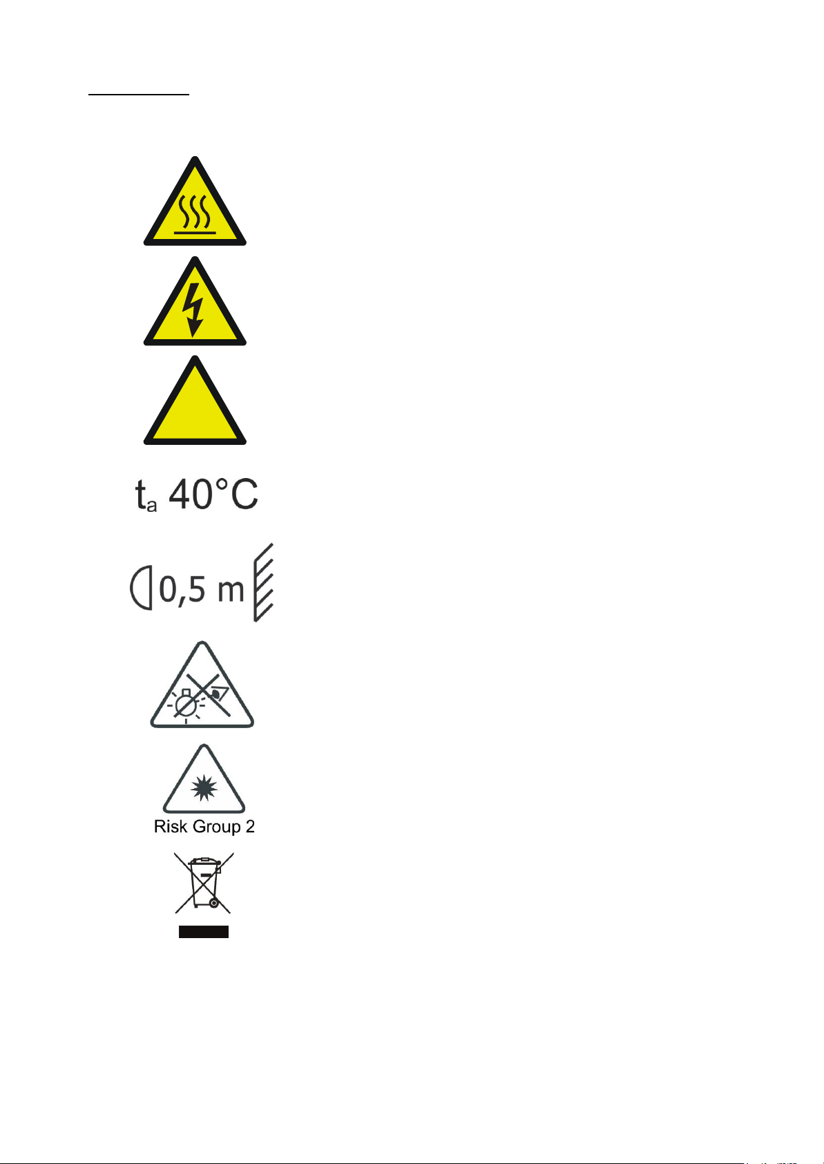
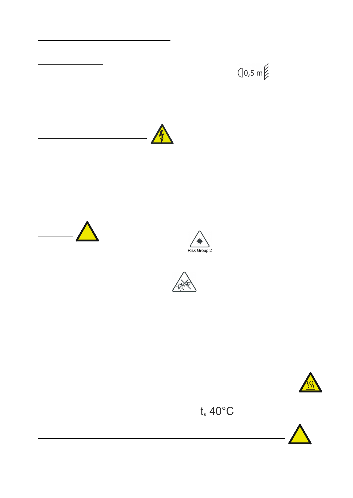
1- SYMBOLS
Graphic symbols used on this manual:
THIS SYMBOL INDICATES A HOT SURFACE
THIS SYMBOL INDICATES ELECTRIC
SHOCK RISK
THIS SYMBOL INDICATES GENERAL RISK
THIS SYMBOL INDICATES THE MAXIMUM
OPERATING AMBIENT TEMPERATURE
THIS SYMBOL INDICATES THE MINIMUM
DISTANCE FROM THE ILLUMINATED OBJECTS
THIS SYMBOL MEANS “DO NOT STARE
AT THE OPERATING LIGHT SOURCE”
THIS SYMBOL INDICATES
PHOTOBIOLOGICAL SAFETY
THIS SYMBOL INDICATES THE EUROPEAN
COMMUNITY DIRECTIVE 2012/19/EC ON
WASTE ELECTRICAL AND ELECTRONIC
EQUIPMENT (WEEE)
!
Page 5

5
2- GENERAL WARNING
Read the instruction contained in this user manual carefully, as they give important
information regarding safety during installation, use and maintenance.
The unit is not for household use and must be installed by a qualified electrician or
experienced person.
Always disconnect the device from the mains before maintenance.
The device must always be equipped with an efficient ground connection.
3- GENERAL WARRANTY CONDITIONS
The unit is guaranteed for 36 months from the date of purchase against manufacturing
material defects.
The warranty covers defects in materials and workmanship. The warranty is not
appliable where a defect is caused by misuse or unauthorised repair of the product.
Any functional or/and physical modification of the product is not allowed.
4- TECHNICAL FEATURES
DTS product codes:
03.LDB130S11FC X-BRICK FC Ultra-Narrow lenses Black finishing
Output
32 OSTAR STAGE “N” Full Color (RGBW) LEDs
15.300 lumens output
LED lifespan: 50.000 hours (70% lumen output)
Optical group
8° projection angle
Range of quick-mounting holographic filters included: 20° / 40° / 60°x10° (no mounting
tools required)
Uniform projection on surfaces
Color generation
16 million colors
Wide palette of pure uniform Whites with variable linear color temperature (2700K –
8000K)
16 gel filter emulations
Control
Wireless DMX transmitter/receiver (built-in)
DMX 512 / RDM protocols
LCD display + 4 capacitive touch keys
Internal operating system updatable via DTS Dongle Firmware Uploader
9 DMX modes:
DMX Full Operation modes
- Chase (default)
- Extended
- Sectors RGBW X4
- Sectors RGBW Fine X4
- Sectors RGBW + Shut + Dim X4
Page 6
6
DMX Single Layer modes (compatibility with all BRICK models)
- Standard
- Global RGBW
- Global RGBW + Shut + Dim
- Global RGBW + Dim Fine
Power supply
Built-in full-range PSU 100-240Vac 50-60 Hz
Power consumption: 650W
Connections
PowerCON TRUE1 In/Out IP65 panel connectors with water-proof caps
XLR 5 pins In/Out IP65 panel connectors with water-proof caps
Internal safety devices
Overvoltage and overtemperature circuits protection
Operating ambient temperature
-20° / 40°
Physical
IP65
IK protection degree: IK09
Weight: 14 Kg
Finishing: Black
Certifications
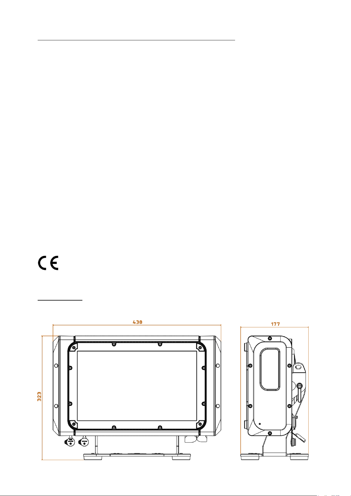
DIMENSIONS
Page 7

7
5- ACCESSORIES
As standard
1 x Holographic filter 20° (code 0506A043.D18)
1 x Holographic filter 40° (code 0506A045.D18)
1 x Holographic filter 60°x10° (code 0506A092.D18)
1 x Cable with PowerCON TRUE1 female connector (code 02K0012267.0015)
1 x XLR 5-pole IP65 female cable connector (code 0508B177)
1 x XLR 5-pole IP65 male cable connector (code 0508B178)
1 x Display UV protection (code 03.LA.218)
1 x Omega bracket with “Fast Lock” (code 02K00467)
1 x User’s Manual
Optional (on request)
- Holographic filter 10° (code 0506A101.D18)
- Holographic filter 60° (code 0506A103.D18)
- Holographic filter 80° (code 0506A121.D18)
- Holographic filter 30x60° (code 0506A133.D18)
- Barndoor black finishing (code 03.LA.237.11)
- Visor black finishing (code 03.LA.236.11)
- Aliscaf clamp for tube diameter 50 mm (Max load 200 Kg) (code 0521A033)
(indicated for any kind of loads vertical / horizontal)
- Professional Quick trigger clamp (Max load 100 Kg) (code 0521A037) (not indicated
for horizontal load)
- “C” Clamp G60 (Max load 50 Kg) (code 0521A004) (not indicated for horizontal load)
- Safety cable 5 x 600 mm (Max load 60 Kg) (code 0521A038)
- DTS Dongle firmware uploader (code 03.LA.206)
Page 8
8
6- IMPORTANT SAFETY INFORMATION
6.1 Fire prevention:
-Minimum distance from the closest illuminable surface: 0,5 m.
- Replace any blown or damaged fuses only with those of identical value.
Attention: the fuse replacement must be made by DTS personnel or experienced
person.
-Connect the unit to mains power via a thermal magnetic circuit breaker.
6.2 Prevention of electric shock:
-High voltage is present inside the unit. Unplug the unit prior to performing any
function which involves touching the inside of the projector.
-The level of technology inherent in the X-BRICK requires the assistance of
specialised personnel for all servicing.
Please refer to an authorised DTS service centre.
-A good earth connection is essential for proper functioning of the unit.
-Never connect the unit without proper earth connection.
-The fixture should be located in places with a good air ventilation.
6.3 Safety:
-Risk Group 2 product according to EN 62471.
CAUTION. Do not look directly into the light output. May be harmful to the eyes and
skin.
-Do not stare at the operating light source.
- The luminaire should be positioned so that prolonged staring into the luminaire at a
distance of 25,94 m is not expected.
-The light source contained in this luminaire shall only be replaced by the
manufacturer or his service agent or a similar qualified person.
-The unit is not for household use and must be installed by a qualified electrician or
experienced person.
-The projector should always be installed with bolts, clamps and other tools that are
capable of supporting the weight of the unit.
-Always use a second safety cable to sustain the weight of the unit in case of the
failure of the main fixing point.
-The external surface of the unit, at various points, may exceed 60°C. Never handle
the unit until at least 5 minutes have elapsed since the projector was turned off.
-Never install the fixture in an enclosed area lacking sufficient air flow.
The ambient temperature should not exceed 40°C.
6.4 Level of protection against the penetration of solid and liquid objects:
-The projector is classified as an outdoor appliance and its protection level against the
penetration of solid and liquid objects is IP65.
Suitable for wet locations.
!
!
Page 9
9
6.5 Waste Electrical and Electronic equipment (WEEE) directive:
-The machine, accessories and packaging should be sorted for environmetal-friendly
Recycling.
For EC countries: according to the European Directive 2012/19/EC for Waste
Electrical and Electronic Equipment and its implementation into national right,
luminaires that are no longer usable must be collected separately and disposed of in
an environmentally correct manner.
7- INSTALLATION
The unit is suitable for wet locations.
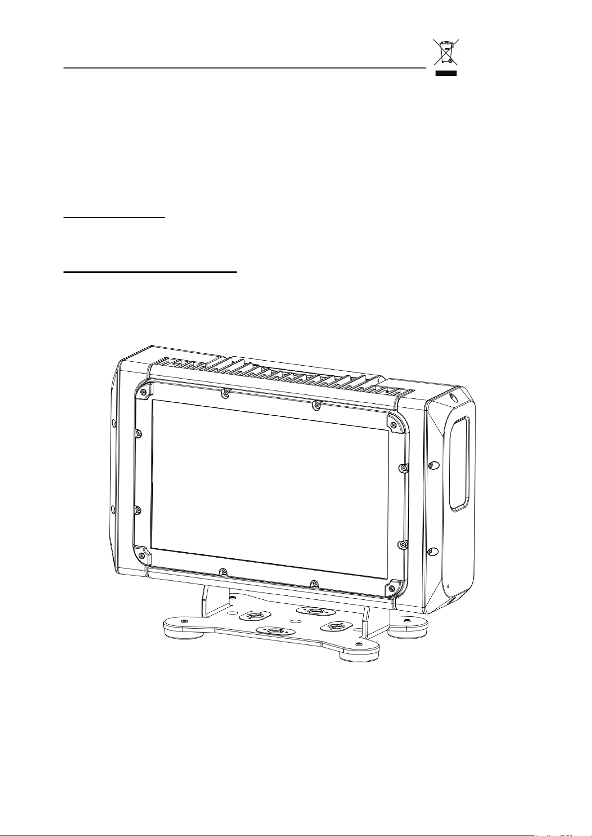
7.1 Floor mounting installation
BRICK may be either floor or ceiling mounted.
For floor mounting installation, X-BRICK is supplied with four rubber mounting feet on
its bracket to be used as a self standing projector.
Page 10
10
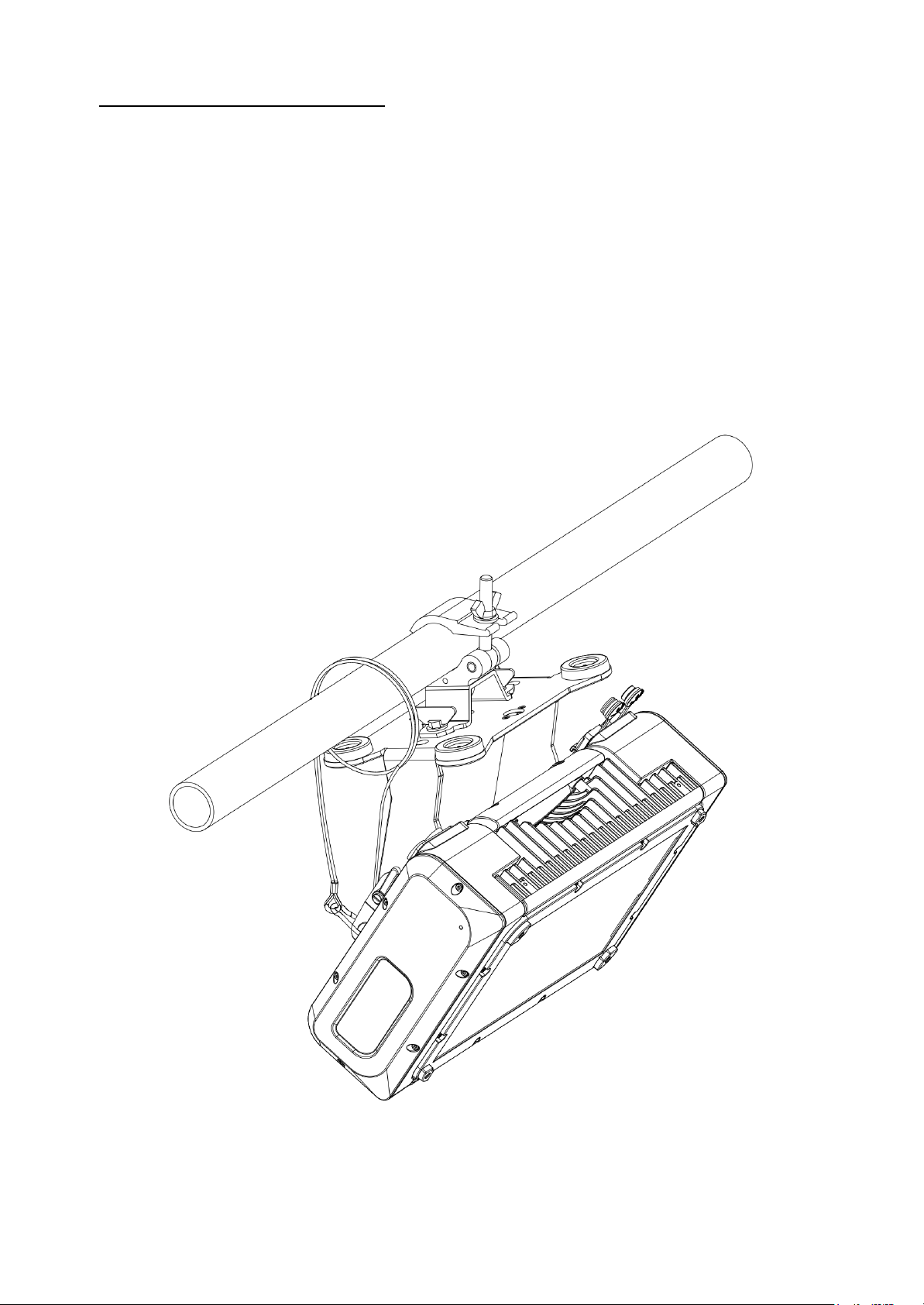
7.2 Ceiling mounting installation
For ceiling mounting installation, it is recommended the use of appropriate clamps to
fix the unit to the mounting surface.
An included Omega bracket with Fast Lock connections allows to hang X-BRICK by
using fixing clamps for truss.
The supporting structure from which the unit is hung should be capable of bearing the
weight of the unit, as should any clamps used to hung it.
For outdoor application where X-BRICK needs to be installed vertically keep the
unit display towards the floor.
ATTENTION:
A safety cable must be securely fixed to the unit’s mounting bracket and to the support
structure of the projector as shown in the picture.
A suitable safety cable (code 0521A038) is available on demand.
Installation with Omega bracket:
Page 11

11
Installation without Omega bracket:
7.3 Display UV Protection
For outdoor installation, X-BRICK is provided with a Display UV protection (code
03.LA.218).
To install the Display UV protection:
Put in place the UV protection plate and the gasket on the display panel and fix both
with the 2 marked screws provided in the kit.
Fix the safety cable on the side cap with the marked screw and the washer provided in
the kit as shown in the picture.
Page 12
12
7.4 Protection against liquids
If IP65 protection is impaired for any reason, do not expose this product to external
atmospheric agents, because it could be damaged.
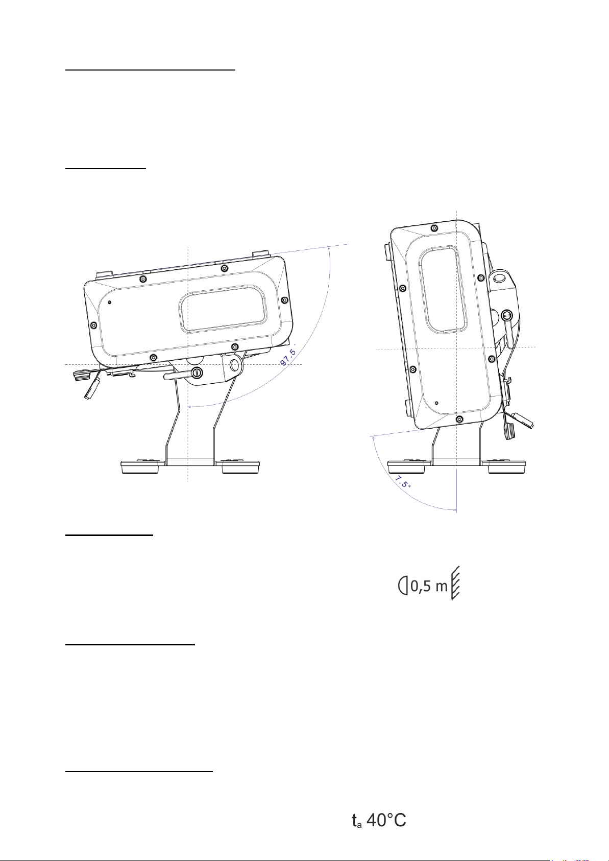
7.5 Movement
The projector has a maximum movement of 105° for Tilt.
7.6- Risk of fire
Each fixture produces heat and must be installed in a well-ventilated place.
Minimum distance from the object being illuminated is 0,5 m.
7.7- Forced ventilation
You will note, on inspection, that the unit features various air inlets and cooling fans.
These should, under no circumstances, be blocked or obstructed whilst the projector is
in operation. Doing so could cause the fixture to seriously overheat thereby
compromising its proper operation.
7.8- Ambient temperature
The projector should never be installed in places that lack a constant air flow.
The ambient temperature should not exceed 40°C.
Page 13
13
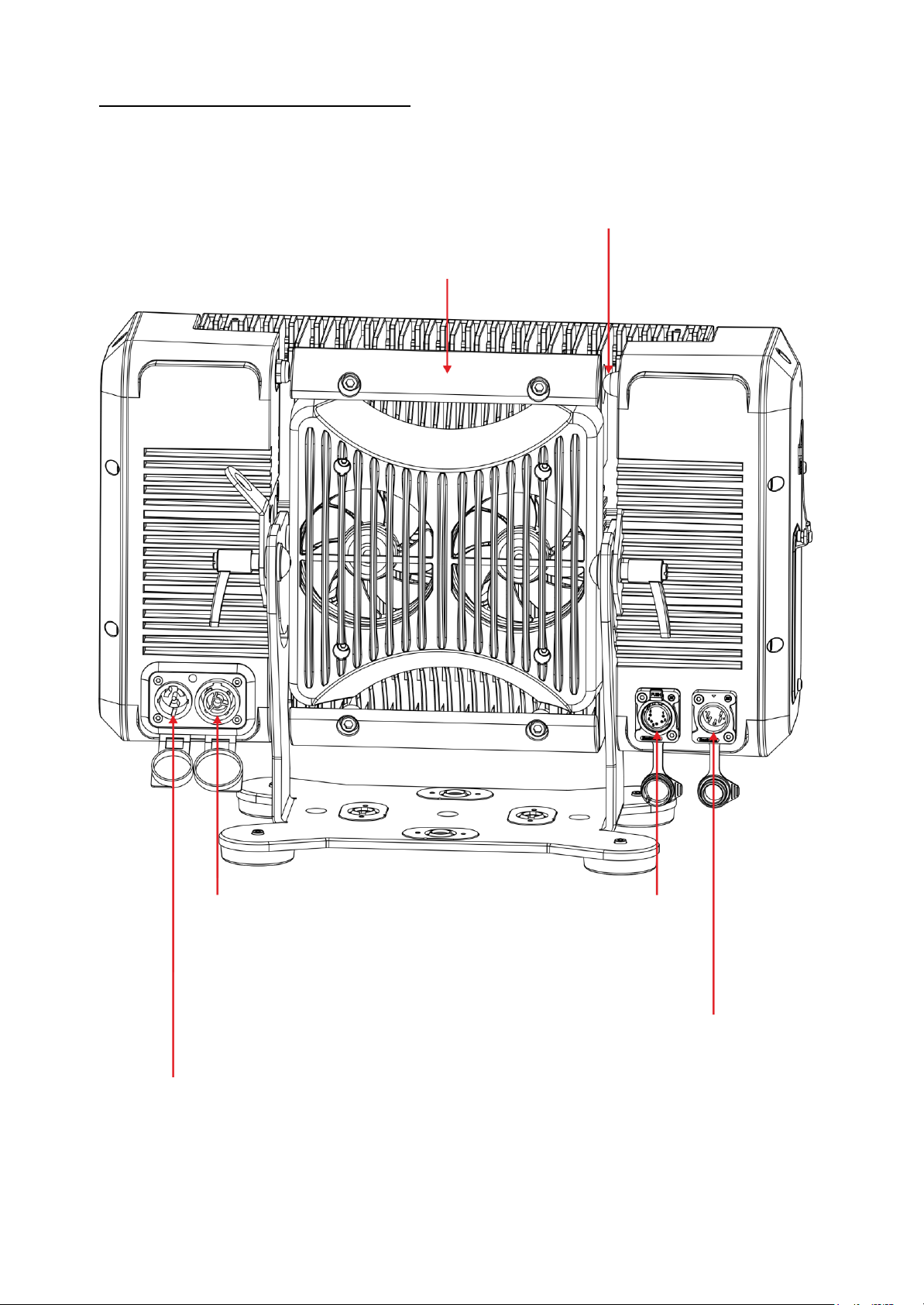
8- INPUT / OUTPUT CONNECTIONS
WIRELESS DMX
Built-in Lumen Radio
Wireless DMX
transmitter/receiver
Ergonomic double handles
MAINS IN
100-240Vac 50-60 Hz
PowerCON TRUE1 male
IP65 panel connector
with water-proof cap
MAINS OUT
100-240Vac 50-60 Hz (MAX 16A)
PowerCON TRUE1 female
IP65 panel connector
with water-proof cap
Max 4 X-BRICK units @ 230Vac
Max 2 X-BRICK units @ 100Vac
DMX OUT
XLR 5-pole female
IP65 panel connector
with water-proof cap
DMX IN
XLR 5-pole male
IP65 panel connector
with water-proof cap
Page 14
14
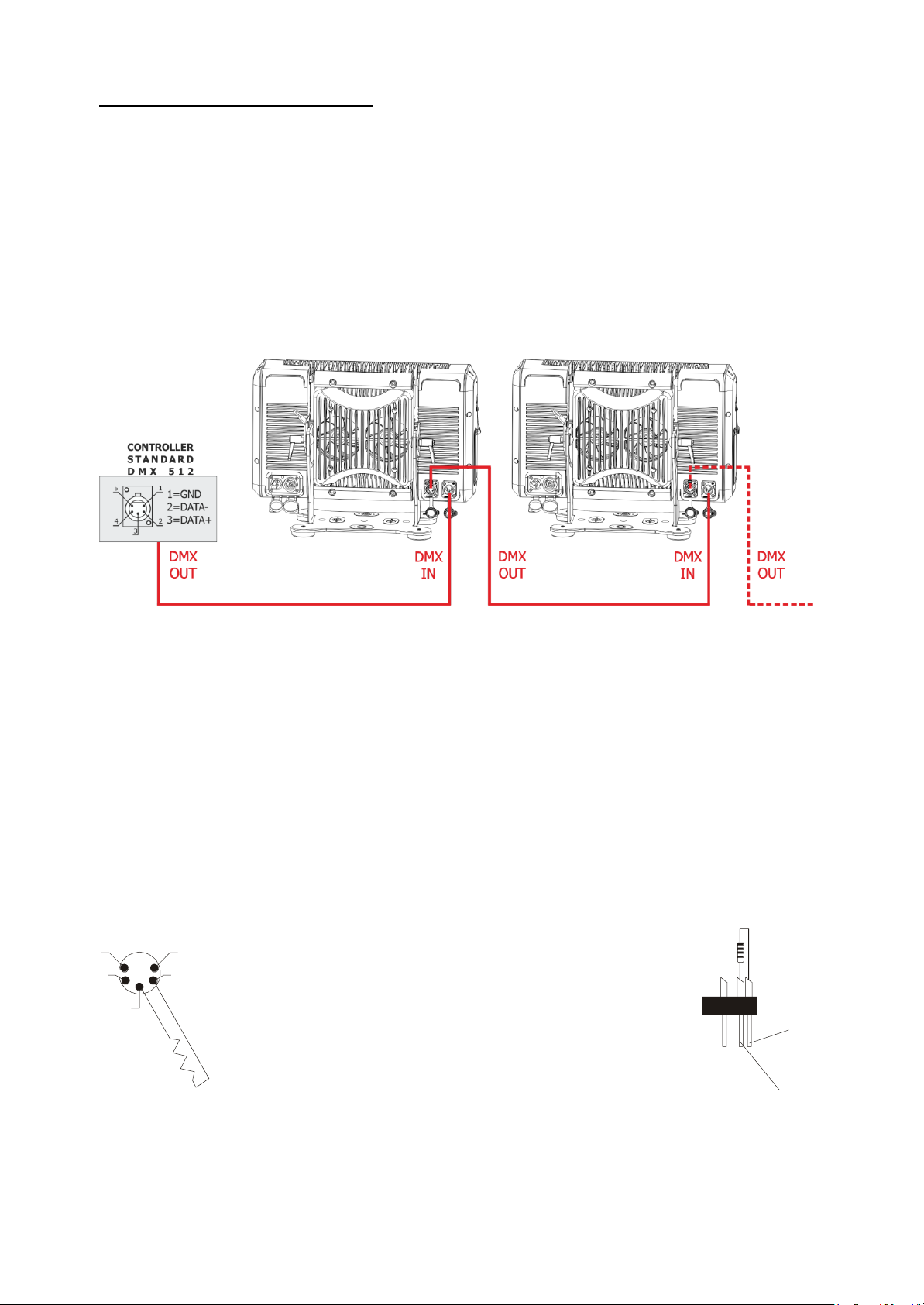
9- DMX SIGNAL CONNECTION:
The unit operates using a digital DMX 512 signal.
Connection between the controller and the unit or between units must be carried out
using a two pair screened ø 0.5 mm.
Ensure that the conductors do not touch each other.
Do not connect the cable ground to the DMX connector chassis.
The plug housing must be isolated. Connect the mixer signal to the DMX IN projector
plug and connect it to the next projector by connecting the DMX OUT plug on the first
unit to the DMX IN plug of the second one.
In this way, all the projectors are cascade connected.
If the display showing the DMX address flashes, then one of the following errors has
occurred:
- DMX signal not present
- DMX reception problem
For Installations where long distance DMX cable connections are needed, we
suggest to use a DMX terminator.
The DMX terminator is a male XLR 3-5 pins connector with a 120 ohm resistor
Between pin 2 and 3.
The DMX terminator must be plugged into the last unit (DMX out panel connector) of
the DMX line.
PLACE A 120 OHM RESISTOR BETWEEN PIN 2
AND 3 OF A MALE XRL CONNECTOR AND PLUG IT
INTO THE DMX OUT PANEL CONNECTOR OF THE
LAST UNIT CONNECTED TO THE DMX LINE
1
2
3
5
4
OUT
120 ohm
PIN 3
PIN 2
Page 15

15
9.1 DMX addresses
X-BRICK can be used in 9 DMX modes:
1. Standard (10 ch)
2. Chase (23 ch) (Default)
3. Extended (29 ch)
4. Global RGBW (4 ch)
5. Global RGBW + Shut + Dim (6 ch)
6. Global RGBW + Dim Fine (10 ch)
7. Sectors RGBW X4 (16 ch)
8. Sectors RGBW Fine X4 (32 ch)
9. Sectors RGBW + Shut + Dim X4 (24 ch)
DMX Full Operation modes
- Chase (default)
- Extended
- Sectors RGBW X4
- Sectors RGBW Fine X4
- Sectors RGBW + Shut + Dim X4
DMX Single Layer modes (compatibility with all BRICK models)
- Standard
- Global RGBW
- Global RGBW + Shut + Dim
- Global RGBW + Dim Fine
In order to use the unit in “Chase” mode (23 DMX channels) (Default), set the following
addresses on the mixer:
Projector 1 A001
Projector 2 A024 If you want to select the next projector, just add “23”
Projector 3 A047
….. A….
projector 6 A116
9.2 Selecting the DMX address
1) Press the UP-DOWN key until you reach the required DMX address. The numbers
on the display will start to flash (but the new DMX address hasn't yet been set).
2) Press ENTER to confirm your selection. The numbers on the display will stop
flashing and the projector is now controlled by the new DMX address.
TIPS: if you keep pushed the UP or DOWN keys, the channels are calculated more
quickly and you get a faster selection.
Page 16
16
10- RDM FUNCTIONS
By using a RDM controller it is possible to set DMX address, DMX mode and other
parameters. X-BRICK accepts the following RDM commands:
RDM Device Model ID: 0x0D65
RDM PID DESCRIPTION
RDM PID VALUE
GET
SET
Category – Network Management
DISC_UNIQUE_BRANCH
0x0001
DISC_MUTE
0x0002
DISC_UN_MUTE
0x0003
Category – Status Collection
STATUS_MESSAGES
0x0030
X
STATUS_ID_DESCRIPTION
0x0031
X
Category - RDM Information
SUPPORTED_PARAMETERS
0x0050
X
PARAMETERS_DESCRIPTION
0x0051
X
Category – Product Information
DEVICE_INFO
0x0060
X
DEVICE_MODEL_DESCRIPTION
0x0080
X
MANUFACTURER_LABEL
0x0081
X
DEVICE_LABEL
0x0082
X
X
SOFTWARE_VERSION_LABEL
0x00C0
X
Category - DMX512 Setup
DMX_PERSONALITY
0x00E0
X
X
DMX_PERSONALITY_DESCRIPTION
0x00E1
X
DMX_START_ADDRESS
0x00F0
X
X
Category – Sensors
SENSOR_DEFINITION
0x0200
X
SENSOR_VALUE
0x0201
X
X
Category – Power/Lamp Settings
DEVICE_HOURS
0x0400
X
LAMP_HOURS
0x0401
X
Category – Display Settings
DISPLAY_INVERT
0x0500
X
X
Category – Control
IDENTIFY_DEVICE
0x1000
X
Category – Dimmer Settings (Additional Messages)
CURVE
0x0343
X
X
CURVE_DESCRIPTION
0x0344
X
OUTPUT_RESPONSE_TIME
0x0345
X
X
OUTPUT_RESPONSE_TIME_DESCRIPTION
0x0346
X
MODULATION_FREQUENCY
0x0347
X
X
MODULATION_FREQUENCY_DESCRIPTION
0x0348
X
Page 17

17
10- RDM FUNCTIONS
RDM PID DESCRIPTION
RDM PID VALUE
GET
SET
Category – Manufacturer-Specific PIDs
LED PIXEL INVERT
0x9039
X
X
FANS SETTING
0x903A
X
X
DISPLAY STANDBY
0x903C
X
X
BKGND-CHS CROSSFADE
0x903D
X
X
NO DMX ACTION
0x9002
X
X
RED NO DMX
0x9003
X
X
GREEN NO DMX
0x9004
X
X
BLUE NO DMX
0x9005
X
X
WHITE NO DMX
0x9006
X
X
INT NO DMX
0x900A
X
X
RED FINE NO DMX
0x9014
X
X
GREEN FINE NO DMX
0x9015
X
X
BLUE FINE NO DMX
0x9016
X
X
WHITE FINE NO DMX
0x9017
X
X
INT FINE NO DMX
0x9018
X
X
RED2 NO DMX
0x9019
X
X
GREEN2 NO DMX
0x901A
X
X
BLUE2 NO DMX
0x901B
X
X
WHITE2 NO DMX
0x901C
X
X
INT2 NO DMX
0x901D
X
X
RED2 FINE NO DMX
0x901E
X
X
GREEN2 FINE NO DMX
0x901F
X
X
BLUE2 FINE NO DMX
0x9020
X
X
WHITE2 FINE NO DMX
0x9021
X
X
INT2 FINE NO DMX
0x9022
X
X
RED3 NO DMX
0x9023
X
X
GREEN3 NO DMX
0x9024
X
X
BLUE3 NO DMX
0x9025
X
X
WHITE3 NO DMX
0x9026
X
X
INT3 NO DMX
0x9027
X
X
RED3 FINE NO DMX
0x9028
X
X
GREEN3 FINE NO DMX
0x9029
X
X
BLUE3 FINE NO DMX
0x902A
X
X
WHITE3 FINE NO DMX
0x902B
X
X
INT3 FINE NO DMX
0x902C
X
X
RED4 NO DMX
0x902D
X
X
GREEN4 NO DMX
0x902E
X
X
BLUE4 NO DMX
0x902F
X
X
WHITE4 NO DMX
0x9030
X
X
INT4 NO DMX
0x9031
X
X
RED4 FINE NO DMX
0x9032
X
X
GREEN4 FINE NO DMX
0x9033
X
X
BLUE4 FINE NO DMX
0x9034
X
X
WHITE4 FINE NO DMX
0x9035
X
X
INT4 FINE NO DMX
0x9036
X
X
Page 18
18
10- RDM FUNCTIONS
RDM ADDITIONAL MESSAGEs:
CURVE
CURVE DESCRIPTION
1
1: LINEAR
2
2: QUADRATIC (default)
3
3: S-CURVE
4
4: GAMMA 2.2
OUTPUT RESPONSE TIME
OUTPUT_RESPONSE_TIME_DESCRIPTION
0
0: SMOOTH OFF
1
1: SMOOTH 1 ( 25 ms)
2
2: SMOOTH 2 ( 50 ms)
3
3: SMOOTH 3 ( 75 ms)
4
4: SMOOTH 4 (100 ms) (default)
5
5: SMOOTH 5 (125 ms)
6
6: SMOOTH 6 (150 ms)
7
7: SMOOTH 7 (175 ms)
8
8: SMOOTH 8 (200 ms)
9
9: SMOOTH 9 (225 ms)
10
10: SMOOTH 10 (250 ms)
11
11: SMOOTH 11 (275 ms)
12
12: SMOOTH 12 (300 ms)
13
13: SMOOTH 13 (325 ms)
14
14: SMOOTH 14 (350 ms)
15
15: SMOOTH 15 (375 ms)
16
16: SMOOTH 16 (400 ms)
17
17: SMOOTH 17 (425 ms)
18
18: SMOOTH 18 (450 ms)
19
19: SMOOTH 19 (475 ms)
20
20: SMOOTH 20 (500 ms)
Page 19

19
10- RDM FUNCTIONS
RDM ADDITIONAL MESSAGEs:
MODULATION FREQUENCY
MODULATION FREQUENCY DESCRIPTION
1
1: 610 Hz
2
2: 800 Hz
3
3: 1000 Hz (default)
4
4: 1500 Hz
5
5: 2000 Hz
6
6: 2500 Hz
7
7: 3000 Hz
8
8: 3500 Hz
9
9: 4000 Hz
10
10: 4500 Hz
11
11: 5000 Hz
RDM MANUFACTURER-SPECIFIC PIDs:
MANUFACTURER-SPECIFIC PID
DESCRIPTION
LED PIXEL INVERT
0 = Disabled (default)
1 = Enabled
FANS SETTING
0 = Fan mode Standard (default)
1 = Fan mode Silent
2 = Fan mode Ultra-Silent
3 = Fan mode Auto
DISPLAY STANDBY
0 = DISABLED (Default)
1 = ENABLED
2 = FORCED ENABLED
NO DMX ACTION
1 = BLACKOUT
2 = PROGRAM 1-16
3 = RGB 100%
4 = RGB 60%
5 = CUSTOM
6 = CUSTOM2
7 = CUSTOM3
8 = CUSTOM4
9 = KEEP LAST (default)
Page 20

20
RDM MANUFACTURER-SPECIFIC PIDs:
MANUFACTURER-SPECIFIC PID
DESCRIPTION
RED NO DMX
Range 0-255 (Default = 128)
GREEN NO DMX
Range 0-255 (Default = 128)
BLUE NO DMX
Range 0-255 (Default = 128)
WHITE NO DMX
Range 0-255 (Default = 128)
INT NO DMX
Range 0-255 (Default = 128)
RED FINE NO DMX
Range 0-255 (Default = 128)
GREEN FINE NO DMX
Range 0-255 (Default = 128)
BLUE FINE NO DMX
Range 0-255 (Default = 128)
WHITE FINE NO DMX
Range 0-255 (Default = 128)
INT FINE NO DMX
Range 0-255 (Default = 128)
RED2 NO DMX
Range 0-255 (Default = 128)
GREEN2 NO DMX
Range 0-255 (Default = 128)
BLUE2 NO DMX
Range 0-255 (Default = 128)
WHITE2 NO DMX
Range 0-255 (Default = 128)
INT2 NO DMX
Range 0-255 (Default = 128)
RED2 FINE NO DMX
Range 0-255 (Default = 128)
GREEN2 FINE NO DMX
Range 0-255 (Default = 128)
BLUE2 FINE NO DMX
Range 0-255 (Default = 128)
WHITE2 FINE NO DMX
Range 0-255 (Default = 128)
INT2 FINE NO DMX
Range 0-255 (Default = 128)
RED3 NO DMX
Range 0-255 (Default = 128)
GREEN3 NO DMX
Range 0-255 (Default = 128)
BLUE3 NO DMX
Range 0-255 (Default = 128)
WHITE3 NO DMX
Range 0-255 (Default = 128)
INT3 NO DMX
Range 0-255 (Default = 128)
RED3 FINE NO DMX
Range 0-255 (Default = 128)
GREEN3 FINE NO DMX
Range 0-255 (Default = 128)
BLUE3 FINE NO DMX
Range 0-255 (Default = 128)
WHITE3 FINE NO DMX
Range 0-255 (Default = 128)
INT3 FINE NO DMX
Range 0-255 (Default = 128)
RED4 NO DMX
Range 0-255 (Default = 128)
GREEN4 NO DMX
Range 0-255 (Default = 128)
BLUE4 NO DMX
Range 0-255 (Default = 128)
WHITE4 NO DMX
Range 0-255 (Default = 128)
INT4 NO DMX
Range 0-255 (Default = 128)
RED4 FINE NO DMX
Range 0-255 (Default = 128)
GREEN4 FINE NO DMX
Range 0-255 (Default = 128)
BLUE4 FINE NO DMX
Range 0-255 (Default = 128)
WHITE4 FINE NO DMX
Range 0-255 (Default = 128)
INT4 FINE NO DMX
Range 0-255 (Default = 128)
Page 21

21
10- RDM FUNCTIONS
RDM STATUS MESSAGE IDs:
Status Message ID
Data Value 1
Data Value 2
Status ID Description
0x8008
ERROR SUPPLY VOLTAGE TOO LOW
0x8009
ERROR SUPPLY VOLTAGE TOO HIGH
0x800B
ERROR BUS LED DRIVER
0x801F
ERROR TEMPERATURE LED MODULE
0x8020
1: DRV1
2: DRV2
12: DRV1&DRV2
ERROR TEMPERATURE LED DRIVER %d
0x8021
ERROR TEMPERATURE MICRO
0x9000
1: RED
2: GREEN
3: BLUE
4: WHITE
1: SECTOR 1
2: SECTOR 2
3: SECTOR 3
4: SECTOR 4
ERROR LED %%d SECT %%d OPEN
0x9001
1: RED
2: GREEN
3: BLUE
4: WHITE
1: SECTOR 1
2: SECTOR 2
3: SECTOR 3
4: SECTOR 4
ERROR LED %%d SECT %%d SHORT
0x9010
ERROR TEMPERATURE PSU
11- FIRMWARE UPDATING
To update the firmware release of the X-BRICK you need:
- DTS Dongle Firmware Uploader (code 03.LA.206).
- “DTS Firmware Upgrade Utility v.2.02” program installed on PC.
- Latest firmware release available for X-BRICK unit.
Updating the firmware release.
Please follow the procedure below to perform the update:
1. Connect the DTS Dongle Firmware Uploader to a spare USB port on the PC.
2. Connect the unit DMX input to the DTS Dongle Firmware Uploader DMX output with
a standard DMX cable and turn ON the unit.
3. Send the new firmware release into the unit by using “DTS Firmware Upgrade
Utility v.2.02” program. At the end of the procedure, the unit will reset.
For more information please refer to an authorised DTS service centre.
Page 22

22
12- DISPLAY FUNCTIONS
The X-BRICK display panel shows all the available control menus.
Using these options, it is possible to change the fixture’s setting.
Changing the DTS settings can vary the functions of the unit so that it does not
respond to the DMX 512 used to control it. Carefully follow the instructions below
before carrying out any variations or selections.
MENU
• To access the control menus in the display panel.
• To return to the previous level in the menu structure without
making a change.
• To exit the menus.
ENTER
• To select any required menu.
• To confirm any changes.
UP / DOWN
• To navigate the menus structure.
• To change any value.
MASTER FIRMWARE RELEASE
SLAVE FIRMWARE RELEASE
1.00
1.00
RDM Device Model ID
0x0D65
DMX Personality IDs
0x01 “STANDARD (10CH)”
0x02 “CHASE (23CH)”
0x03 “EXTENDED (29CH)”
0x04 “GLOBAL RGBW (4CH)”
0x05 “GLOBAL RGBW+SHUT+DIM (6CH)”
0x06 “GLOBAL RGBW+DIM FINE (10CH)”
0x07 “SECTORS RGBW X4 (16CH)”
0x08 “SECTORS RGBW FINE X4 (32CH)”
0x09 “SECTORS RGBW+SHUT+DIM X4 (24CH)”
DISPLAY KEY-LOCK FUNCTION
Display key-lock function can be enabled/disabled by pressing ENTER + DOWN keys
at the same time for 3 seconds.
Page 23

23
MAIN MENU
LEVEL 1
LEVEL 2
LEVEL 3
FUNCTION
DISPLAY
FLIP
SUSPENDED
Reverses display’s
reading depending on
the mounting position.
On the ground or
suspended.
Suspended (Default).
ON THE
GROUND
STANDBY
DISABLED
Display stand-by
disabled (Default).
ENABLED
Display goes OFF
after 10 seconds.
FORCED EN.
Display forced OFF
even if control signal is
missing or error
messages are shown.
MODE
1 – 10CH
STANDARD
Allows to select
STANDARD mode (10
DMX channels).
Single layer operation
for compatibility with
all BRICK models.
2 – 23CH
CHASE
Allows to select
CHASE mode (23
DMX channels).
Default
3 – 29CH
EXTENDED
Allows to select
EXTENDED mode (29
DMX channels).
4 – 4CH
GLOBAL RGBW
Allows to select
GLOBAL RGBW mode
(4 DMX channels).
Single layer operation
for compatibility with
all BRICK models.
5 – 6CH
GLOBAL
RGBW+SHUT+DIM
Allows to select
GLOBAL
RGBW+SHUT+DIM
mode (6 DMX
channels).
Single layer operation
for compatibility with
all BRICK models.
6 – 10CH
GLOBAL
RGBW+DIM FINE
Allows to select
GLOBAL RGBW+DIM
FINE mode (10 DMX
channels).
Single layer operation
for compatibility with
all BRICK models.
7 – 16CH
SECTORS RGBW
X4
Allows to select
SECTORS RGBW
mode (16 DMX
channels).
8 – 32CH
SECTORS RGBW
FINE X4
Allows to select
SECTORS RGBW
FINE X4 mode (32
DMX channels).
9 – 24CH
SECTORS RGBW
+SHUT+DIM X4
Allows to select
SECTORS
RGBW+SHUT+DIM
X4 mode (24 DMX
channels).
Page 24

24
MAIN MENU
LEVEL 1
LEVEL 2
LEVEL 3
FUNCTION
NO DMX
ACTION
KEEP LAST DMX
Allows to set the
desired unit’s behavior
in case DMX signal is
missing or not
available.
Keep last valid DMX
signal (Default).
BLACKOUT
Black-out.
PROGRAM 1-16
1 - 16
Chase with 16 steps
previously created in
REC mode. Speed
time and wait time
values (in seconds)
selectable by user.
Default = 10.
SPEED
1 - 3600
WAIT
1 - 3600
RGB 100
RGB channels @
100%.
RGB 60
RGB channels @ 60%.
CUSTOM
RED
0 - 255
Custom.
RGBW, RGBW Fine
and Dimmer values
selectable by user.
Default = 128.
RED FINE
0 - 255
Default = 128.
GREEN
0 - 255
Default = 128.
GREEN FINE
0 - 255
Default = 128.
BLUE
0 - 255
Default = 128.
BLUE FINE
0 - 255
Default = 128.
WHITE
0 - 255
Default = 128.
WHITE FINE
0 - 255
Default = 128.
DIMMER
0 - 255
Default = 128.
DIMMER FINE
0 - 255
Default = 128.
CUSTOM2
Custom2.
RGBW, RGBW Fine
and Dimmer values
selectable by user only
via RDM.
CUSTOM3
Custom3.
RGBW, RGBW Fine
and Dimmer values
selectable by user only
via RDM.
CUSTOM4
Custom4.
RGBW, RGBW Fine
and Dimmer values
selectable by user only
via RDM.
Page 25

25
MAIN MENU
LEVEL 1
LEVEL 2
LEVEL 3
FUNCTION
MODE AUTO
PROGRAM 1-16
1 - 16
Automatic mode
without DMX controller.
Chase with 16 steps
previously created in
REC mode.
Speed time and wait
time values (in
seconds) selectable by
user (Default = 10).
In Auto mode the unit
do generate DMX for
slave units.
SPEED
1 - 3600
WAIT
1 - 3600
PERS. COLOUR
1 - 16
16 customizable
Colour Macros.
RGBW values
selectable by user
(Default = 255).
RAINBOW
SPEED
Rainbow colours
effect.
Speed time value (in
seconds) selectable by
user (Default = 10).
FIXED COLOUR
1 - 28
28 Colour Macros as
on DMX channel
“MACRO COLOR”.
Default = 1.
CCT
2700 - 8000
12 White color
temperature from
2700K to 8000K as on
DMX channel “CCT”.
Default = 2700K.
DIMMER
0 - 255
Dimmer level
selectable by user as
on DMX channel
“DIMMER”
Default = 255.
SHUTTER
0 - 255
Shutter level selectable
by user as on DMX
channel “SHUTTER”
Default = 15.
ESC
Esc from automatic
mode.
REC
10 CH
R001
In DMX Recorder
mode it is possible to
create and store the
scenes of the
PROGRAM 1-16 menu
by using an external
DMX controller.
The unit must be set to
10 DMX channels
mode.
Refer to “REC MODE”
for details.
M001 – M016
SLAVE
SURE
SLAVE
Slave mode.
The unit is forced to
DMX address 1 and 10
DMX channels mode
receiving signal from
the unit set in Auto
mode.
ESC
Esc from slave mode
Page 26

26
MAIN MENU
LEVEL 1
LEVEL 2
LEVEL 3
FUNCTION
WIRELESS
STATUS
DISABLED
Allows to control the
unit via Wireless DMX.
Default = Disabled.
ENABLED
DIRECTION
RECEIVER
The unit receives
signal via Wireless
DMX and transmit the
signal to the DMX
Output connector
(Default).
TRANSMITTER
The unit works as
Wireless DMX
Transmitter.
The unit receives
signal from DMX Input
connector and transmit
the signal via Wireless.
UNLINK
Operation as Receiver:
To log off the unit from
paired wireless
transmitter device.
Operation as
Transmitter:
To log off all the paired
wireless receiver
devices.
ONLY FOR
TRANSMITTER
LINK
To log on all the free
wireless receiver
devices.
WIRELESS
X-BRICK features a built-in Lumen Radio Wireless DMX transmitter/receiver.
Operation as Receiver (default)
Enable Wireless DMX control under WIRELESS -> STATUS menu.
On the main display will appear “WIRELESS RX” (Default) above the DMX address.
To log on the unit to Lumen Radio or Wireless Solution compatible transmitter devices,
press the connect button on the wireless transmitter device.
To optimize the wireless communication maintain TX to RX line of sight.
The maximum distance should not exceed 100 meters.
Select UNLINK menu to log off the unit from paired wireless trasmitter device.
Operation as Transmitter
Enable Wireless DMX control under WIRELESS -> STATUS menu.
Set the unit as Transmitter under DIRECTION -> TRANSMITTER menu.
On the main display will appear “WIRELESS TX” above the DMX address.
Connect the unit via DMX Input connector and pair the free wireless receiver devices
by selecting LINK menu.
To optimize the wireless communication maintain TX to RX line of sight.
The maximum distance should not exceed 100 meters.
Select UNLINK menu to log off all the paired wireless receiver devices.
Page 27

27
MAIN MENU
LEVEL 1
LEVEL 2
LEVEL 3
FUNCTION
LED
SMOOTH
OFF - 20
Allows to select the
value of delay (in ms)
for DIMMER channel
reaction to DMX
dimming command.
OFF = Instant
response.
4 = 100 ms smooth
response (Default).
20 = 500 ms smooth
response.
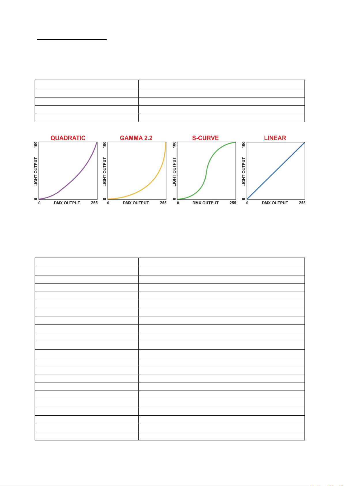
COMP
QUADRATIC
Allows to set
quadratic current
output for LED
(Default).
GAMMA 2.2
Allows to set gamma
curve 2.2 .
S-CURVE
Allows to set S-curve
to emulates light
intensity characteristics
of the tungsten
halogen lamps.
LINEAR
Allows to set linear
light output.
SYNC
610 - 5000 HZ
Allows to adjust the
PWM frequency value
(Hz) in order to reduce
flickering in the
process of your
camera recordings.
Range = 610 Hz –
5000 Hz
Default = 1000 Hz
BKG-CHS
CROSSFADE
TRANSITION
Allows to set
Crossfade Transition
from background to
chase/sector of DMX
modes 2 and 3.
(Default).
INTERMEDIATE
Allows to set
Crossfade
Intermediate from
background to
chase/sector of DMX
modes 2 and 3.
LED PIXEL INVERT
NORMAL
Standard pixel/sectors
sequence.
Normal = Default.
REVERSE
To invert pixel/sectors
sequence.
Refer to page 35 for
details.
“COMP” GRAPHICS:
“CROSSFADE” GRAPHICS:
Page 28

28
MAIN MENU
LEVEL 1
LEVEL 2
LEVEL 3
FUNCTION
FAN
STANDARD
Fans standard speed
(Default).
If temperature <15°C:
fans OFF.
If temperature >15°C:
fans speed is
increased within the
factory values range.
SILENT
Reduced fans speed
for a low noise
operation.
If temperature <15°C:
fans OFF.
If temperature >15°C:
fans speed is
increased within the
factory values range.
ULTRA SILENT
Low fans speed for a
very low noise
operation.
If temperature <15°C:
fans OFF.
If temperature >15°C:
fans speed is
increased within the
factory values range.
AUTO
Automatic fans speed.
If temperature <40°C:
fans OFF.
If temperature >40°C:
fans speed is
increased related to
system working
conditions.
DEFAULT SET
SURE
To restore factory
settings.
SYSTEM INFO
TEMPERATURE
DRV1 41.4 40.8
DRV2 40.5 41.0
LED 48.2
PSU 43.4
MICRO 1 46.6
MICRO 2 45.5
DRV-1: LED Driver
Master board temperature
monitoring.
DRV-2: LED Driver Slave
board temperature
monitoring.
LED: LED temperature
monitoring.
PSU: Power supply
temperature monitoring.
MICRO 1: Micro controller
of LED Driver Master
board temperature
monitoring.
MICRO 2: Micro controller
of LED Driver Slave board
temperature monitoring.
SOFTWARE
MASTER
DRV1 V.1.00
SLAVE
DRV2 V.1.00
LED Driver Master and
Slave board firmware
release.
TIME COUNTERS
S1 (R G B W)
S2 (R G B W)
S3 (R G B W)
S4 (R G B W)
UNIT LIFE
RGBW LEDs life time
for each sector and
unit life time.
LEDS STATUS
S1 (R G B W)
S2 (R G B W)
S3 (R G B W)
S4 (R G B W)
RGBW LEDs status
monitoring for each
sector:
NA = Not available.
OK = LEDs properly
working.
SH = LEDs in short
circuit.
OP = LEDs in open
circuit.
Page 29

29
13- REC MODE
DMX Recorder mode
For the programming of ChPr by using a DMX controller, besides the 10 channels necessary
to control the unit a further 3 DMX channels are needed.
So that in RECORDER mode (via DMX) the unit will need 13 channels to be correctly
programmed.
The three new DMX channels are:
DMX channel 11 = SCENES channel
From 0-10 = no function (r001)
From 11-255 are displayed the programmable scenes (max 16 scenes from M001 to M0016)
DMX channel 12 = EDIT channel:
-From 0-19 = no function
-From 20-234 the unit runs the configuration given by the received input DMX values.
With the channel SCENES it is possible to pass from one step to the next while with REC it is
possible to record the selected scene.
-From 235-255 the unit runs the configuration given by the received input DMX values closing
the sequence as last scene.
With the channel REC it is possible to record the selected scene as last scene.
DMX channel 13 = RECORDING channel
Records the set scene with a variation between 0 to 255 (the display flashes indicating that
the scene has been recorded). It is advised that you keep the REC channel set to 0 and to run
through the 255 only once you have decided to save the scene. If ChPr is not closed, by
indicating the last scene (Edit channel between 235-255), in playback mode all 16 scenes will
be played through even if not programmed.
Page 30

30
14- ERROR MESSAGES
ERROR SHOWED ON DISPLAY
APPEARS WHEN
LED SENSOR ERROR
LED thermal sensor damaged (open or in
short circuit).
Unit immediately goes in black-out.
LED OVERTEMP
LED temperature detected over 100°C.
Unit immediately goes in black-out.
DRV1 MICRO SENSOR ERROR
Micro controller thermal sensor on LED
Driver Master board damaged (open or in
short circuit).
Unit immediately goes in black-out.
DRV1 MICRO OVERTEMP
Temperature of Micro controller on LED
Driver Master board detected over 100°C.
Unit immediately goes in black-out.
DRV2 MICRO SENSOR ERROR
Micro controller thermal sensor on LED
Driver Slave board damaged (open or in
short circuit).
Unit immediately goes in black-out.
DRV2 MICRO OVERTEMP
Temperature of Micro controller on LED
Driver Slave board detected over 100°C.
Unit immediately goes in black-out.
DRV1 NTC1 SENSOR ERROR
Thermal sensor on outputs 6 and 7 of LED
Driver Master board damaged (open or in
short circuit).
Unit immediately goes in black-out.
DRV1 NTC1 OVERTEMP
Temperature detected over 100°C on
outputs 6 and 7 of LED Driver Master
board. Unit immediately goes in black-out.
DRV1 NTC3 SENSOR ERROR
Thermal sensor on outputs 2 and 3 of LED
Driver Master board damaged (open or in
short circuit).
Unit immediately goes in black-out.
DRV1 NTC3 OVERTEMP
Temperature detected over 100°C on
outputs 2 and 3 of LED Driver Master
board. Unit immediately goes in black-out.
DRV2 NTC1 SENSOR ERROR
Thermal sensor on outputs 6 and 7 of LED
Driver Slave board damaged (open or in
short circuit).
Unit immediately goes in black-out.
DRV2 NTC1 OVERTEMP
Temperature detected over 100°C on
outputs 6 and 7 of LED Driver Slave
board. Unit immediately goes in black-out.
DRV2 NTC3 SENSOR ERROR
Thermal sensor on outputs 2 and 3 of LED
Driver Slave board damaged (open or in
short circuit).
Unit immediately goes in black-out.
DRV2 NTC3 OVERTEMP
Temperature detected over 100°C on
outputs 2 and 3 of LED Driver Slave
board. Unit immediately goes in black-out.
Page 31

31
14- ERROR MESSAGES
ERROR SHOWED ON DISPLAY
APPEARS WHEN
PSU SENSOR ERROR
PSU thermal sensor damaged (open or in
short circuit).
Unit immediately goes in black-out.
PSU OVERTEMP
PSU temperature detected over 100°C.
Unit immediately goes in black-out.
DRV2 COMMUNICATION ERROR
Communication problem between LED
Driver Master board and LED Driver Slave
board.
DRV1 LOW SUPPLY VOLTAGE
LED Driver Master board input voltage
<36Vdc.
DRV1 HIGH SUPPLY VOLTAGE
LED Driver Master board input voltage
>50Vdc.
DRV2 LOW SUPPLY VOLTAGE
LED Driver Slave board input voltage
<36Vdc.
DRV2 HIGH SUPPLY VOLTAGE
LED Driver Slave board input voltage
>50Vdc.
15- PERIODIC CLEANING
Lenses Front Glass:
The dust can reduce the luminous output substantially. Reqularly clean the lenses
front glass using a soft cotton cloth, dampened with a specialist glasses cleaning
solution.
16- PERIODIC CONTROLS
Mechanical parts:
Periodically check all mechanical parts and the gaskets. Please refer to an authorised
DTS service centre for any operation involving of the unit if needed.
Electrical components:
Check for unit proper earthing. Please refer to an authorised DTS service centre for
any operation involving of the unit if needed.
Fuse replacement:
Using a multimeter, test the condition of the fuse, replacing it with one of equivalent
type. Disconnect mains prior to remove the fuse to be tested.
Attention: the fuse replacement must be made by DTS personnel or
experienced person.
Page 32

32
17- HOLOGRAPHIC FILTER INSTALLATION
X-BRICK offers a range of holographic filters quickly interchangeable (no tools
required).
To properly install the holographic filter:
1 - Put in place the bottom edge of the filter.
2 - Bend the filter.
3 - Insert the top edge of the filter.
For permanent outdoor installation, the holographic filter can also be mounted
internally.
To remove the filter simply lift with a finger the filter on the side with the opening as
shown in the picture.
Page 33

33
18- VISOR INSTALLATION
The Visor for X-BRICK (code 03.LA.236.11) is available on demand.
Fix the Visor on the X-BRICK by using the 4 marked screws previously removed from
the unit body.
Once installed, fix the safety cable on the side cap by using the marked screw and the
washer provided in the box as shown in the picture.
Page 34

34
19- BARNDOOR INSTALLATION
The Barndoor for X-BRICK (code 03.LA.237.11) is available on demand.
Fix the Barndoor on the X-BRICK by using the 4 marked screws previously removed
from the unit body.
Once installed, fix the safety cable on the side cap by using the marked screw and the
washer provided in the box as shown in the picture.
Page 35

35
20- LED PIXEL INVERT FUNCTION REFERENCES
Page 36

36
21- DMX PROTOCOL
1. “STANDARD” mode (10 DMX channels)
1 RED
2 GREEN
3 BLUE
4 WHITE
5 SHUTTER
6 DIMMER
7 DIMMER FINE
8 CCT
9 MACRO COLOR
10 FUNCTIONS
Dmx Personality 1: STANDARD (10 channels)
#
Name
Dmx Levels Ranges And Functions
1
RED
0..255
Proportional color from min to max
2
GREEN
0..255
Proportional color from min to max
3
BLUE
0..255
Proportional color from min to max
4
WHITE
0..255
Proportional color from min to max
5
SHUTTER
0..9
Blackout
10..19
Open
20..29
Blackout
30..119
Strobe (from 3,27 s to 30 ms)
120..149
Pulse up (from 42,6 s to 120 ms)
150..179
Pulse down (from 42,6 s to 120 ms)
180..204
Random strobe
205..229
Full independent random strobe
230..255
Open
6
DIMMER
0..255
Proportional master dimmer
From Off (lev. 0) to Full On (lev.255)
7
DIMMER FINE
0..255
Proportional master dimmer fine
From Off (lev. 0) to Full On (lev.255)
8
CCT
0..10
No Function
11..255
Correlated colour temperature from 2700K to 8000K.
Relevant CCT values:
11
2700 K
33
3000 K
55
3200 K
77
3500 K
99
4000 K
121
4500 K
143
5000 K
165
5600 K
187
6000 K
209
6500 K
232
7000 K
255
8000 K
Page 37

37
Dmx Personality 1: STANDARD (10 channels)
#
Name
Dmx Levels Ranges And Functions
9
MACRO COLOR
0..14
No function
15..24
COL 1: LEE FILTER NO. 19 "FIRE"
(R255 G64 B0 W0)
25..34
COL 2: LEE FILTER NO. 20 "MEDIUM AMBER"
(R255 G146 B0 W0)
35..44
COL 3: LEE FILTER NO. 25 "SUNSET RED"
(R255 G111 B23 W0)
45..54
COL 4: LEE FILTER NO. 101 "YELLOW"
(R255 G186 B0 W0)
55..64
COL 5: LEE FILTER NO. 104 "DEEP AMBER"
(R255 G182 B0 W0)
65..74
COL 6: LEE FILTER NO. 106 "PRIMARY RED"
(R255 G0 B0 W0)
75..84
COL 7: LEE FILTER NO. 111 "DARK PINK"
(R255 G0 B0 W157)
85..94
COL 8: LEE FILTER NO. 113 "MAGENTA"
(R255 G28 B28 W45)
95..104
COL 9: LEE FILTER NO. 118 "LIGHT BLUE"
(R0 G252 B115 W101)
105..114
COL 10: LEE FILTER NO. 122 "FERN GREEN"
(R171 G255 B0 W70)
115..124
COL 11: LEE FILTER NO. 126 "MAUVE"
(R255 G0 B118 W0)
125..134
COL 12: LEE FILTER NO. 137 "LAVANDER"
(R243 G224 B112 W97)
135..144
COL 13: LEE FILTER NO. 139 "PRIMARY GREEN"
(R87 G255 B0 W0)
145..154
COL 14: LEE FILTER NO. 147 "APRICOT"
(R204 G127 B23 W42)
155..164
COL 15: LEE FILTER NO. 154 "PALE ROSE"
(R255 G167 B0 W139)
165..174
COL 16: LEE FILTER NO. 181 "CONGO BLUE"
(R94 G107 B255 W0)
175..184
RGB RAINBOW COLOR MIXING: SPEED 1 (6 SEC.)
185..194
RGB RAINBOW COLOR MIXING: SPEED 2 (15 SEC.)
195..204
RGB RAINBOW COLOR MIXING: SPEED 3 (30 SEC.)
205..214
RGB RAINBOW COLOR MIXING: SPEED 4 (45 SEC.)
215..224
RGB RAINBOW COLOR MIXING: SPEED 5 (60 SEC.)
225..234
RGB RAINBOW COLOR MIXING: SPEED 6 (120 SEC.)
235..244
RGB RAINBOW COLOR MIXING: SPEED 7 (150 SEC.)
245..255
RGB RAINBOW COLOR MIXING: SPEED 8 (180 SEC.)
10
FUNCTIONS
Activated by staying on
desired option for 5
seconds
0..14
No function
15..24
SMOOTH OFF
25..26
SMOOTH 1
27..28
SMOOTH 2
29..30
SMOOTH 3
31..32
SMOOTH 4 (DEFAULT)
33..34
SMOOTH 5
35..36
SMOOTH 6
37..38
SMOOTH 7
39..40
SMOOTH 8
41..42
SMOOTH 9
43..44
SMOOTH 10
45..46
SMOOTH 11
47..48
SMOOTH 12
49..50
SMOOTH 13
51..52
SMOOTH 14
53..54
SMOOTH 15
55..56
SMOOTH 16
Page 38

38
Dmx Personality 1: STANDARD (10 channels)
#
Name
Dmx Levels Ranges And Functions
10
FUNCTIONS
Activated by staying on
desired option for 5
seconds
57..58
SMOOTH 17
59..60
SMOOTH 18
61..62
SMOOTH 19
63..64
SMOOTH 20
65..66
GAMMA CORRECTION QUADRATIC (DEFAULT)
67..68
GAMMA CORRECTION LINEAR
69..70
GAMMA CORRECTION S-CURVE
71..72
GAMMA CORRECTION 2.2
73..74
RESERVED
75..76
RESERVED
77..78
RESERVED
79..80
CROSSFADE CURVE INTERMEDIATE
81..82
CROSSFADE CURVE TRANSITION (DEFAULT)
83..84
RESERVED
85..104
OUTPUT FREQUENCY 610 Hz
105
OUTPUT FREQUENCY 800 Hz
106
OUTPUT FREQUENCY 1000 Hz (DEFAULT)
107
OUTPUT FREQUENCY 1500 Hz
108
OUTPUT FREQUENCY 2000 Hz
109
OUTPUT FREQUENCY 2500 Hz
110
OUTPUT FREQUENCY 3000 Hz
111
OUTPUT FREQUENCY 3500 Hz
112
OUTPUT FREQUENCY 4000 Hz
113
OUTPUT FREQUENCY 4500 Hz
114
OUTPUT FREQUENCY 5000 Hz
115..134
RESERVED
135..144
RESERVED
145..154
RESERVED
155..164
DISPLAY STAND BY DISABLED (DEFAULT)
165..172
DISPLAY STAND BY ENABLED
173..174
DISPLAY STAND BY FORCED ENABLED
175..176
NO DMX ACTION – KEEP LAST DMX (DEFAULT)
177..178
NO DMX ACTION – BLACK OUT
179..180
NO DMX ACTION – RGB@100% (WHITE CHANNEL OFF)
181..182
NO DMX ACTION – CHPR (PROGRAM STEPS 01..16)
WAIT and SPEED time selectable via “NDMX>PROGRAM 1-16” menu
183..184
NO DMX ACTION – CUSTOM
(RGBW values selectable via “NDMX>CUSTOM” menu or via RDM Custom PID
185..194
RESERVED
195..204
RESERVED
205..214
RESERVED
215..224
RESERVED
225..228
RESERVED
229.230
RESERVED
231.232
RESERVED
233..234
RESERVED
235..242
FAN STANDARD MODE (DEFAULT)
243..244
FAN AUTO MODE
245..250
FAN SILENT MODE
251..252
FAN ULTRA SILENT MODE
253..255
SET DEFAULTS FOR ALL FUNCTION CHANNEL PARAMETERS
Page 39

39
2. “CHASE” mode (23 DMX channels) (Default)
1 RED BACKGROUND
2 GREEN BACKGROUND
3 BLUE BACKGROUND
4 WHITE BACKGROUND
5 SHUTTER
6 DIMMER
7 DIMMER FINE
8 CCT BACKGROUND
9 MACRO COLOR BACKGROUND
10 FUNCTIONS
11 BACKGROUND SELECTION
12 COLOR MERGING MODE
13 CROSSFADE BACKGROUND/CHASE
14 CHASE SELECTION
15 CHASE RED
16 CHASE GREEN
17 CHASE BLUE
18 CHASE WHITE
19 CHASE STROBE (Priority on SHUTTER channel)
20 CHASE SIZE/SPEED
21 CHASE X-FADE
22 CHASE OFFSET
23 CHASE FADE TIME
Dmx Personality 2: CHASE (23 channels)
#
Name
Dmx Levels Ranges And Functions
1
RED
Background
0..255
Proportional color from min to max
2
GREEN
Background
0..255
Proportional color from min to max
3
BLUE
Background
0..255
Proportional color from min to max
4
WHITE
Background
0..255
Proportional color from min to max
5
SHUTTER
0..9
Blackout
10..19
Open
20..29
Blackout
30..119
Strobe (from 3,27 s to 30 ms)
120..149
Pulse up (from 42,6 s to 120 ms)
150..179
Pulse down (from 42,6 s to 120 ms)
180..204
Random strobe
205..229
Full independent random strobe
230..255
Open
6
DIMMER
0..255
Proportional master dimmer
From Off (lev. 0) to Full On (lev.255)
7
DIMMER FINE
0..255
Proportional master dimmer fine
From Off (lev. 0) to Full On (lev.255)
8
CCT
Background
0..10
No Function
11..255
Correlated colour temperature from 2700K to 8000K.
Relevant CCT values:
11
2700 K
33
3000 K
55
3200 K
77
3500 K
99
4000 K
121
4500 K
143
5000 K
165
5600 K
187
6000 K
209
6500 K
232
7000 K
255
8000 K
Page 40

40
Dmx Personality 2: CHASE (23 channels)
#
Name
Dmx Levels Ranges And Functions
9
MACRO COLOR
Background
0..14
No function
15..24
COL 1: LEE FILTER NO. 19 "FIRE"
(R255 G64 B0 W0)
25..34
COL 2: LEE FILTER NO. 20 "MEDIUM AMBER"
(R255 G146 B0 W0)
35..44
COL 3: LEE FILTER NO. 25 "SUNSET RED"
(R255 G111 B23 W0)
45..54
COL 4: LEE FILTER NO. 101 "YELLOW"
(R255 G186 B0 W0)
55..64
COL 5: LEE FILTER NO. 104 "DEEP AMBER"
(R255 G182 B0 W0)
65..74
COL 6: LEE FILTER NO. 106 "PRIMARY RED"
(R255 G0 B0 W0)
75..84
COL 7: LEE FILTER NO. 111 "DARK PINK"
(R255 G0 B0 W157)
85..94
COL 8: LEE FILTER NO. 113 "MAGENTA"
(R255 G28 B28 W45)
95..104
COL 9: LEE FILTER NO. 118 "LIGHT BLUE"
(R0 G252 B115 W101)
105..114
COL 10: LEE FILTER NO. 122 "FERN GREEN"
(R171 G255 B0 W70)
115..124
COL 11: LEE FILTER NO. 126 "MAUVE"
(R255 G0 B118 W0)
125..134
COL 12: LEE FILTER NO. 137 "LAVANDER"
(R243 G224 B112 W97)
135..144
COL 13: LEE FILTER NO. 139 "PRIMARY GREEN"
(R87 G255 B0 W0)
145..154
COL 14: LEE FILTER NO. 147 "APRICOT"
(R204 G127 B23 W42)
155..164
COL 15: LEE FILTER NO. 154 "PALE ROSE"
(R255 G167 B0 W139)
165..174
COL 16: LEE FILTER NO. 181 "CONGO BLUE"
(R94 G107 B255 W0)
175..184
RGB RAINBOW COLOR MIXING: SPEED 1 (6 SEC.)
185..194
RGB RAINBOW COLOR MIXING: SPEED 2 (15 SEC.)
195..204
RGB RAINBOW COLOR MIXING: SPEED 3 (30 SEC.)
205..214
RGB RAINBOW COLOR MIXING: SPEED 4 (45 SEC.)
215..224
RGB RAINBOW COLOR MIXING: SPEED 5 (60 SEC.)
225..234
RGB RAINBOW COLOR MIXING: SPEED 6 (120 SEC.)
235..244
RGB RAINBOW COLOR MIXING: SPEED 7 (150 SEC.)
245..255
RGB RAINBOW COLOR MIXING: SPEED 8 (180 SEC.)
10
FUNCTIONS
Activated by staying on
desired option for 5
seconds
0..14
No function
15..24
SMOOTH OFF
25..26
SMOOTH 1
27..28
SMOOTH 2
29..30
SMOOTH 3
31..32
SMOOTH 4 (DEFAULT)
33..34
SMOOTH 5
35..36
SMOOTH 6
37..38
SMOOTH 7
39..40
SMOOTH 8
41..42
SMOOTH 9
43..44
SMOOTH 10
45..46
SMOOTH 11
47..48
SMOOTH 12
49..50
SMOOTH 13
51..52
SMOOTH 14
Page 41

41
Dmx Personality 2: CHASE (23 channels)
#
Name
Dmx Levels Ranges And Functions
10
FUNCTIONS
Activated by staying on
desired option for 5
seconds
53..54
SMOOTH 15
55..56
SMOOTH 16
57..58
SMOOTH 17
59..60
SMOOTH 18
61..62
SMOOTH 19
63..64
SMOOTH 20
65..66
GAMMA CORRECTION QUADRATIC (DEFAULT)
67..68
GAMMA CORRECTION LINEAR
69..70
GAMMA CORRECTION S-CURVE
71..72
GAMMA CORRECTION 2.2
73..74
RESERVED
75..76
RESERVED
77..78
RESERVED
79..80
CROSSFADE CURVE INTERMEDIATE
81..82
CROSSFADE CURVE TRANSITION (DEFAULT)
83..84
RESERVED
85..104
OUTPUT FREQUENCY 610 Hz
105
OUTPUT FREQUENCY 800 Hz
106
OUTPUT FREQUENCY 1000 Hz (DEFAULT)
107
OUTPUT FREQUENCY 1500 Hz
108
OUTPUT FREQUENCY 2000 Hz
109
OUTPUT FREQUENCY 2500 Hz
110
OUTPUT FREQUENCY 3000 Hz
111
OUTPUT FREQUENCY 3500 Hz
112
OUTPUT FREQUENCY 4000 Hz
113
OUTPUT FREQUENCY 4500 Hz
114
OUTPUT FREQUENCY 5000 Hz
115..134
RESERVED
135..144
RESERVED
145..154
RESERVED
155..164
DISPLAY STAND BY DISABLED (DEFAULT)
165..172
DISPLAY STAND BY ENABLED
173..174
DISPLAY STAND BY FORCED ENABLED
175..176
NO DMX ACTION – KEEP LAST DMX (DEFAULT)
177..178
NO DMX ACTION – BLACK OUT
179..180
NO DMX ACTION – RGB@100% (WHITE CHANNEL OFF)
181..182
NO DMX ACTION – CHPR (PROGRAM STEPS 01..16)
WAIT and SPEED time selectable via “NDMX>PROGRAM 1-16” menu
183..184
NO DMX ACTION – CUSTOM
(RGBW values selectable via “NDMX>CUSTOM” menu or via RDM Custom PID
185..194
RESERVED
195..204
RESERVED
205..214
RESERVED
215..224
RESERVED
225..228
RESERVED
229.230
LED PIXEL NORMAL (DEFAULT)
231.232
LED PIXEL REVERSE
Page 42

42
Dmx Personality 2: CHASE (23 channels)
#
Name
Dmx Levels Ranges And Functions
10
FUNCTIONS
Activated by staying on
desired option for 5
seconds
233..234
RESERVED
235..242
FAN STANDARD MODE (DEFAULT)
243..244
FAN AUTO MODE
245..250
FAN SILENT MODE
251..252
FAN ULTRA SILENT MODE
253..255
SET DEFAULTS FOR ALL FUNCTION CHANNEL PARAMETERS
11
BACKGROUND
SELECTION
000..009
All Sectors Active
010..011
Sector 1
012.013
Sector 2
014.015
Sector 3
016.017
Sector 4
018.019
Sector 1+2
020.021
Sector 2+4
022.023
Sector 3+4
024.025
Sector 1+3
026.027
Sector 1+4
028..029
Sector 2+3
030..031
Sector 1+2+4
032..033
Sector 2+3+4
034..035
Sector 1+3+4
036..037
Sector 1+2+4
038..039
All Sectors Inactive
040.255
Reserved – no Function – (same as All Sectors Active)
12
COLOUR MERGING
MODE
0..009
TRANSPARENT MODE
(foreground has priority, black opacity 0%)
010.019
STANDARD MODE
(foreground has priority, black opacity 100%)
020.029
MAXIMUM MODE
030.039
MULTIPLY MODE
040.049
ADDITION MODE
050.059
SUBTRACTION MODE
060..069
INVERT SUBCTRACTION MODE
070..162
FOREGROUND ONLY
163..255
BACKGROUND ONLY
Page 43

43
Dmx Personality 2: CHASE (23 channels)
#
Name
Dmx Levels Ranges And Functions
13
CROSSFADE
BACKGROUND /
CHASE
0..255
CROSSFADE BETWEEN BACKGROUND AND CHASE
TRANSITION (Default):
0= BACKGROUND @100% and Chase@0%
128= BACKGROUND @100% and Chase@100%
255= Chase@100% and BACKGROUND @0%
INTERMEDIATE:
0= BACKGROUND @100% and Chase@0%
128= BACKGROUND @50% and Chase@50%
255= Chase@100% and BACKGROUND @0%
14
CHASE SELECTION
000..009
No Function – All Sectors Inactive
010.011
Sector 1
012.013
Sector 2
014.015
Sector 3
016.017
Sector 4
018.019
Sector 1+2
020.021
Sector 2+4
022.023
Sector 3+4
024.025
Sector 1+3
026.027
Sector 1+4
028..029
Sector 2+3
030..031
Sector 1+2+4
032..033
Sector 2+3+4
034..035
Sector 1+3+4
036..037
Sector 1+2+3
038..039
All Sectors Active
040..171
Dynamic Macro Dimmers 1..66 – 2 steps for each Macro
172..233
Dynamic Macro Colors 1..31 – 2 steps for each Macro
234..240
RESERVED
Page 44

44
Dmx Personality 2: CHASE (23 channels)
#
Name
Dmx Levels Ranges And Functions
14
CHASE SELECTION
241
Hystogram Left Z
Speed is Number of LEDs “ON” from left up side
First N LEDs on the left are on, depending on SPEED channel – Z shape
242
Hystogram Right Z
Speed is Number of LEDs on from Right down side
First N LEDs on the Right are on, depending on SPEED channel – Z shape
243
Hystogram Left C
Speed is Number of LEDs “ON” from left up side
First N LEDs on the left are on, depending on SPEED channel – C shape
244
Histogram Right C
Speed is Number of LEDs on from Right down side
First N LEDs on the Right are on, depending on SPEED channel – C shape
245
Histogram Multicolour Left Z
Speed is Number of LEDs “ON” from left up side
First N LEDs on the left are on with rainbow colours, depending on SIZE/SPD channel – Z shape
246
Histogram Multicolour Right Z
Speed is Number of LEDs on from Right down side
First N LEDs on the Right are on with rainbow colours, depending on SIZE/SPD channel – Z shape
247
Histogram Multicolour Left C
Speed is Number of LEDs “ON” from left up side
First N LEDs on the left are on with rainbow colours, depending on SIZE/SPD channel – C shape
248
Histogram Multicolour Right C
Speed is Number of LEDs on from Right down side
First N LEDs on the Right are on with rainbow colours, depending on SIZE/SPD channel – C shape
249
Wave Right Z
A rainbow with size depending on COLOR channel scrolls to the right with speed dependent on SPEED
channel – Z shape
250
Wave Left Z
A rainbow with size depending on COLOR channel scrolls to the left with speed dependent on SPEED
channel – Z shape
251
Wave Right C
A rainbow with size depending on COLOR channel scrolls to the right with speed dependent on SPEED
channel – C shape
252
Wave Left C
A rainbow with size depending on COLOR channel scrolls to the left with speed dependent
on SPEED channel – C shape
253
Pulse
SPEED is Effect Speed.
A strip of multicolour pixels grows and shrinks
254.255
Random Pick
Every 15 s a new random effect is chosen from the above spacial effects (240..253) effects or Dynamic Macro
Colors (272..233)
15
CHASE
RED
0..255
Chase colour – RED component
16
CHASE
GREEN
0..255
Chase colour – GREEN component
17
CHASE
BLUE
0..255
Chase colour – BLUE component
18
CHASE
WHITE
0..255
Chase colour – WHITE component
Page 45

45
Dmx Personality 2: CHASE (23 channels)
#
Name
Dmx Levels Ranges And Functions
19
CHASE STROBE
Priority on SHUTTER
channel
0..9
No Function : SUBJECT TO CHANNEL 5 SHUTTER
(DEFAULT)
10..19
Open
20..29
Blackout
30..119
Strobe (from 3,27 s to 30 ms)
120..149
Pulse up (from 42,6 s to 120 ms)
150..179
Pulse down (from 42,6 s to 120 ms)
180..204
Random strobe
205..229
Reserved – No Function SUBJECT TO CHANNEL 5 SHUTTER
230..255
Open
20
CHASE
SIZE/SPEED
0.127
Indexed 0..360°
128.179
Left rotation fast to slow
180.202
stop
203.255
Right rotation slow to fast
21
CHASE X-FADE
0..255
Transition between Steps of the same Chase from Snap/instant to Smooth.
0 = 0% Transition (Snap/instant Transition)
255 = 100% Transition (Smooth Transition)
22
CHASE OFFSET
0..255
Chase offset (0° to 360°) - phase shift or shape modifier
23
CHASE FADE TIME
0..255
Fade Time transition between two different Chases
0= no Fade – 1..255 Fade Time from Min (0s) to Max (4s)
3. “EXTENDED” mode (29 DMX channels)
1 RED BACKGROUND
2 GREEN BACKGROUND
3 BLUE BACKGROUND
4 WHITE BACKGROUND
5 SHUTTER
6 DIMMER
7 DIMMER FINE
8 CCT BACKGROUND
9 MACRO COLOR BACKGROUND
10 FUNCTIONS
11 BACKGROUND SELECTION
12 COLOR MERGING MODE
13 CROSSFADE BACKGROUND/CHASE
14 SECTOR 1 RED
15 SECTOR 1 GREEN
16 SECTOR 1 BLUE
17 SECTOR 1 WHITE
18 SECTOR 2 RED
19 SECTOR 2 GREEN
20 SECTOR 2 BLUE
21 SECTOR 2 WHITE
22 SECTOR 3 RED
23 SECTOR 3 GREEN
24 SECTOR 3 BLUE
25 SECTOR 3 WHITE
26 SECTOR 4 RED
27 SECTOR 4 GREEN
28 SECTOR 4 BLUE
29 SECTOR 4 WHITE
Page 46

46
Dmx Personality 3: EXTENDED ( 29 channels)
#
Name
Dmx Levels Ranges And Functions
1
RED
Background
0..255
Proportional color from min to max
2
GREEN
Background
0..255
Proportional color from min to max
3
BLUE
Background
0..255
Proportional color from min to max
4
WHITE
Background
0..255
Proportional color from min to max
5
SHUTTER
0..9
Blackout
10..19
Open
20..29
Blackout
30..119
Strobe (from 3,27 s to 30 ms)
120..149
Pulse up (from 42,6 s to 120 ms)
150..179
Pulse down (from 42,6 s to 120 ms)
180..204
Random strobe
205..229
Full independent random strobe
230..255
Open
6
DIMMER
0..255
Proportional master dimmer
From Off (lev. 0) to Full On (lev.255)
7
DIMMER FINE
0..255
Proportional master dimmer fine
From Off (lev. 0) to Full On (lev.255)
8
CCT
Background
0..10
No Function
11..255
Correlated colour temperature from 2700K to 8000K.
Relevant CCT values:
11
2700 K
33
3000 K
55
3200 K
77
3500 K
99
4000 K
121
4500 K
143
5000 K
165
5600 K
187
6000 K
209
6500 K
232
7000 K
255
8000 K
Page 47

47
Dmx Personality 3: EXTENDED (29 channels)
#
Name
Dmx Levels Ranges And Functions
9
MACRO COLOR
Back ground
0..14
No function
15..24
COL 1: LEE FILTER NO. 19 "FIRE"
(R255 G64 B0 W0)*
25..34
COL 2: LEE FILTER NO. 20 "MEDIUM AMBER"
(R255 G146 B0 W0)
35..44
COL 3: LEE FILTER NO. 25 "SUNSET RED"
(R255 G111 B23 W0)
45..54
COL 4: LEE FILTER NO. 101 "YELLOW"
(R255 G186 B0 W0)
55..64
COL 5: LEE FILTER NO. 104 "DEEP AMBER"
(R255 G182 B0 W0)
65..74
COL 6: LEE FILTER NO. 106 "PRIMARY RED"
(R255 G0 B0 W0)
75..84
COL 7: LEE FILTER NO. 111 "DARK PINK"
(R255 G0 B0 W157)
85..94
COL 8: LEE FILTER NO. 113 "MAGENTA"
(R255 G28 B28 W45)
95..104
COL 9: LEE FILTER NO. 118 "LIGHT BLUE"
(R0 G252 B115 W101)
105..114
COL 10: LEE FILTER NO. 122 "FERN GREEN"
(R171 G255 B0 W70)
115..124
COL 11: LEE FILTER NO. 126 "MAUVE"
(R255 G0 B118 W0)
125..134
COL 12: LEE FILTER NO. 137 "LAVANDER"
(R243 G224 B112 W97)
135..144
COL 13: LEE FILTER NO. 139 "PRIMARY GREEN"
(R87 G255 B0 W0)
145..154
COL 14: LEE FILTER NO. 147 "APRICOT"
(R204 G127 B23 W42)
155..164
COL 15: LEE FILTER NO. 154 "PALE ROSE"
(R255 G167 B0 W139)
165..174
COL 16: LEE FILTER NO. 181 "CONGO BLUE"
(R94 G107 B255 W0)
175..184
RGB RAINBOW COLOR MIXING: SPEED 1 (6 SEC.)
185..194
RGB RAINBOW COLOR MIXING: SPEED 2 (15 SEC.)
195..204
RGB RAINBOW COLOR MIXING: SPEED 3 (30 SEC.)
205..214
RGB RAINBOW COLOR MIXING: SPEED 4 (45 SEC.)
215..224
RGB RAINBOW COLOR MIXING: SPEED 5 (60 SEC.)
225..234
RGB RAINBOW COLOR MIXING: SPEED 6 (120 SEC.)
235..244
RGB RAINBOW COLOR MIXING: SPEED 7 (150 SEC.)
245..255
RGB RAINBOW COLOR MIXING: SPEED 8 (180 SEC.)
Page 48

48
Dmx Personality 3: EXTENDED (29 channels)
#
Name
Dmx Levels Ranges And Functions
10
FUNCTIONS
Activated by staying on
desired option for 5
seconds
0..14
No function
15..24
SMOOTH OFF
25..26
SMOOTH 1
27..28
SMOOTH 2
29..30
SMOOTH 3
31..32
SMOOTH 4 (DEFAULT)
33..34
SMOOTH 5
35..36
SMOOTH 6
37..38
SMOOTH 7
39..40
SMOOTH 8
41..42
SMOOTH 9
43..44
SMOOTH 10
45..46
SMOOTH 11
47..48
SMOOTH 12
49..50
SMOOTH 13
51..52
SMOOTH 14
53..54
SMOOTH 15
55..56
SMOOTH 16
57..58
SMOOTH 17
59..60
SMOOTH 18
61..62
SMOOTH 19
63..64
SMOOTH 20
65..66
GAMMA CORRECTION QUADRATIC (DEFAULT)
67..68
GAMMA CORRECTION LINEAR
69..70
GAMMA CORRECTION S-CURVE
71..72
GAMMA CORRECTION 2.2
73..74
RESERVED
75..76
RESERVED
77..78
RESERVED
79..80
CROSSFADE CURVE INTERMEDIATE
81..82
CROSSFADE CURVE TRANSITION (DEFAULT)
83..84
RESERVED
85..104
OUTPUT FREQUENCY 610 Hz
105
OUTPUT FREQUENCY 800 Hz
106
OUTPUT FREQUENCY 1000 Hz (DEFAULT)
107
OUTPUT FREQUENCY 1500 Hz
108
OUTPUT FREQUENCY 2000 Hz
109
OUTPUT FREQUENCY 2500 Hz
110
OUTPUT FREQUENCY 3000 Hz
111
OUTPUT FREQUENCY 3500 Hz
112
OUTPUT FREQUENCY 4000 Hz
113
OUTPUT FREQUENCY 4500 Hz
114
OUTPUT FREQUENCY 5000 Hz
115..134
RESERVED
135..144
RESERVED
145..154
RESERVED
155..164
DISPLAY STAND BY DISABLED (DEFAULT)
165..172
DISPLAY STAND BY ENABLED
173..174
DISPLAY STAND BY FORCED ENABLED
175..176
NO DMX ACTION – KEEP LAST DMX (DEFAULT)
177..178
NO DMX ACTION – BLACK OUT
179..180
NO DMX ACTION – RGB@100% (WHITE CHANNEL OFF)
181..182
NO DMX ACTION – CHPR (PROGRAM STEPS 01..16)
WAIT and SPEED time selectable via “NDMX>PROGRAM 1-16” menu
183..184
NO DMX ACTION – CUSTOM
(RGBW values selectable via “NDMX>CUSTOM” menu or via RDM Custom PID
Page 49

49
Dmx Personality 3: EXTENDED (29 channels)
#
Name
Dmx Levels Ranges And Functions
10
FUNCTIONS
Activated by staying on
desired option for 5
seconds
185..194
RESERVED
195..204
RESERVED
205..214
RESERVED
215..224
RESERVED
225..228
RESERVED
229.230
LED PIXEL NORMAL (DEFAULT)
231.232
LED PIXEL REVERSE
233..234
RESERVED
235..242
FAN STANDARD MODE (DEFAULT)
243..244
FAN AUTO MODE
245..250
FAN SILENT MODE
251..252
FAN ULTRA SILENT MODE
253..255
SET DEFAULTS FOR ALL FUNCTION CHANNEL PARAMETERS
11
BACKGROUND
SELECTION
000..009
All Sectors Active
010..011
Sector 1
012.013
Sector 2
014.015
Sector 3
016.017
Sector 4
018.019
Sector 1+2
020.021
Sector 2+4
022.023
Sector 3+4
024.025
Sector 1+3
026.027
Sector 1+4
028..029
Sector 2+3
030..031
Sector 1+2+4
032..033
Sector 2+3+4
034..035
Sector 1+3+4
036..037
Sector 1+2+4
038..039
All Sectors Inactive
040.255
Reserved – no Function – (same as All Sectors Active)
Page 50

50
Dmx Personality 3: EXTENDED (29 channels)
#
Name
Dmx Levels Ranges And Functions
12
COLOUR MERGING
MODE
0..009
TRANSPARENT MODE
(foreground has priority, black opacity 0%)
010.019
STANDARD MODE
(foreground has priority, black opacity 100%)
020.029
MAXIMUM MODE
030.039
MULTIPLY MODE
040.049
ADDITION MODE
050.059
SUBTRACTION MODE
060..069
INVERT SUBCTRACTION MODE
070..162
FOREGROUND ONLY
163..255
BACKGROUND ONLY
13
CROSSFADE
BACKGROUND /
CHASE
0..255
CROSSFADE BETWEEN BACKGROUND AND CHASE
TRANSITION (Default):
0= BACKGROUND @100% andChase@0%
128= BACKGROUND @100% and Chase@100%
255= Chase@100% and BACKGROUND @0%
INTERMEDIATE:
0= BACKGROUND @100% and Chase@0%
128= BACKGROUND @50% and Chase@50%
255= Chase@100% and BACKGROUND @0%
Page 51

51
Dmx Personality 3: EXTENDED (29 channels)
#
Name
Dmx Levels Ranges And Functions
14
SECTOR 1
RED
0..255
Proportional RED
From Off (lev. 0) to Full On (lev.255)
15
SECTOR 1
GREEN
0..255
Proportional GREEN
From Off (lev. 0) to Full On (lev.255)
16
SECTOR 1
BLUE
0..255
Proportional BLUE
From Off (lev. 0) to Full On (lev.255)
17
SECTOR 1
WHITE
0..255
Proportional WHITE
From Off (lev. 0) to Full On (lev.255)
18
SECTOR 2
RED
0..255
Proportional RED
From Off (lev. 0) to Full On (lev.255)
19
SECTOR 2
GREEN
0..255
Proportional GREEN
From Off (lev. 0) to Full On (lev.255)
20
SECTOR 2
BLUE
0..255
Proportional BLUE
From Off (lev. 0) to Full On (lev.255)
21
SECTOR 2
WHITE
0..255
Proportional WHITE
From Off (lev. 0) to Full On (lev.255)
22
SECTOR 3
RED
0..255
Proportional RED
From Off (lev. 0) to Full On (lev.255)
23
SECTOR 3
GREEN
0..255
Proportional GREEN
From Off (lev. 0) to Full On (lev.255)
24
SECTOR 3
BLUE
0..255
Proportional BLUE
From Off (lev. 0) to Full On (lev.255)
25
SECTOR 3
WHITE
0..255
Proportional WHITE
From Off (lev. 0) to Full On (lev.255)
26
SECTOR 4
RED
0..255
Proportional RED
From Off (lev. 0) to Full On (lev.255)
27
SECTOR 4
GREEN
0..255
Proportional GREEN
From Off (lev. 0) to Full On (lev.255)
28
SECTOR 4
BLUE
0..255
Proportional BLUE
From Off (lev. 0) to Full On (lev.255)
29
SECTOR 4
WHITE
0..255
Proportional WHITE
From Off (lev. 0) to Full On (lev.255)
4. “GLOBAL RGBW” mode (4 DMX channels)
1 RED
2 GREEN
3 BLUE
4 WHITE
Dmx Personality 4: GLOBAL RGBW (4 channels)
#
Name
Dmx Levels Ranges And Functions
1
RED
0..255
Proportional color from min to max
2
GREEN
0..255
Proportional color from min to max
3
BLUE
0..255
Proportional color from min to max
4
WHITE
0..255
Proportional color from min to max
Page 52

52
5. “GLOBAL RGBW+SHUT+DIMM” mode (6 DMX channels)
1 RED
2 GREEN
3 BLUE
4 WHITE
5 SHUTTER
6 DIMMER
Dmx Personality 5: GLOBAL RGBW + SHUT + DIMM (6 channels)
#
Name
Dmx Levels Ranges And Functions
1
RED
0..255
Proportional color from min to max
2
GREEN
0..255
Proportional color from min to max
3
BLUE
0..255
Proportional color from min to max
4
WHITE
0..255
Proportional color from min to max
5
SHUTTER
0..9
Blackout
10..19
Open
20..29
Blackout
30..119
Strobe (from 3,27 s to 30 ms)
120..149
Pulse up (from 42,6 s to 120 ms)
150..179
Pulse down (from 42,6 s to 120 ms)
180..204
Random strobe
205..229
Full independent random strobe
230..255
Open
6
DIMMER
0..255
Proportional master dimmer
From Off (lev. 0) to Full On (lev.255)
6. “GLOBAL RGBW FINE+DIM FINE” mode (10 DMX channels)
1 RED
2 RED FINE
3 GREEN
4 GREEN FINE
5 BLUE
6 BLUE FINE
7 WHITE
8 WHITE FINE
9 DIMMER
10 DIMMER FINE
Dmx Personality 6: GLOBAL RGBW FINE + DIM FINE (10 channels)
#
Name
Dmx Levels Ranges And Functions
1
RED
0..255
Proportional RED
From Off (lev. 0) to Full On (lev.255)
2
RED FINE
0..255
Proportional RED fine
From Off (lev. 0) to Full On (lev.255)
3
GREEN
0..255
Proportional GREEN
From Off (lev. 0) to Full On (lev.255)
4
GREEN FINE
0..255
Proportional GREEN fine
From Off (lev. 0) to Full On (lev.255)
5
BLUE
0..255
Proportional BLUE
From Off (lev. 0) to Full On (lev.255)
6
BLUE FINE
0..255
Proportional BLUE fine
From Off (lev. 0) to Full On (lev.255)
7
WHITE
0..255
Proportional WHITE
From Off (lev. 0) to Full On (lev.255)
8
WHITE FINE
0..255
Proportional WHITE fine
From Off (lev. 0) to Full On (lev.255)
9
DIMMER
0..255
Proportional master dimmer
From Off (lev. 0) to Full On (lev.255)
10
DIMMER FINE
0..255
Proportional master dimmer fine
From Off (lev. 0) to Full On (lev.255)
Page 53

53
7. “SECTORS RGBW” mode (16 DMX channels)
1 SECTOR 1 RED
2 SECTOR 1 GREEN
3 SECTOR 1 BLUE
4 SECTOR 1 WHITE
5 SECTOR 2 RED
6 SECTOR 2 GREEN
7 SECTOR 2 BLUE
8 SECTOR 2 WHITE
9 SECTOR 3 RED
10 SECTOR 3 GREEN
11 SECTOR 3 BLUE
12 SECTOR 3 WHITE
13 SECTOR 4 RED
14 SECTOR 4 GREEN
15 SECTOR 4 BLUE
16 SECTOR 4 WHITE
Dmx Personality 7: SECTORS RGBW (16 channels)
#
Name
Dmx Levels Ranges And Functions
1
SECTOR 1
RED
0..255
Proportional RED
From Off (lev. 0) to Full On (lev.255)
2
SECTOR 1
GREEN
0..255
Proportional GREEN
From Off (lev. 0) to Full On (lev.255)
3
SECTOR 1
BLUE
0..255
Proportional BLUE
From Off (lev. 0) to Full On (lev.255)
4
SECTOR 1
WHITE
0..255
Proportional WHITE
From Off (lev. 0) to Full On (lev.255)
5
SECTOR 2
RED
0..255
Proportional RED
From Off (lev. 0) to Full On (lev.255)
6
SECTOR 2
GREEN
0..255
Proportional GREEN
From Off (lev. 0) to Full On (lev.255)
7
SECTOR 2
BLUE
0..255
Proportional BLUE
From Off (lev. 0) to Full On (lev.255)
8
SECTOR 2
WHITE
0..255
Proportional WHITE
From Off (lev. 0) to Full On (lev.255)
9
SECTOR 3
RED
0..255
Proportional RED
From Off (lev. 0) to Full On (lev.255)
10
SECTOR 3
GREEN
0..255
Proportional GREEN
From Off (lev. 0) to Full On (lev.255)
11
SECTOR 3
BLUE
0..255
Proportional BLUE
From Off (lev. 0) to Full On (lev.255)
12
SECTOR 3
WHITE
0..255
Proportional WHITE
From Off (lev. 0) to Full On (lev.255)
13
SECTOR 4
RED
0..255
Proportional RED
From Off (lev. 0) to Full On (lev.255)
14
SECTOR 4
GREEN
0..255
Proportional GREEN
From Off (lev. 0) to Full On (lev.255)
15
SECTOR 4
BLUE
0..255
Proportional BLUE
From Off (lev. 0) to Full On (lev.255)
16
SECTOR 4
WHITE
0..255
Proportional WHITE
From Off (lev. 0) to Full On (lev.255)
Page 54

54
8. “SECTORS RGBW FINE” mode (32 DMX channels)
1 SECTOR 1 RED
2 SECTOR 1 RED FINE
3 SECTOR 1 GREEN
4 SECTOR 1 GREEN FINE
5 SECTOR 1 BLUE
6 SECTOR 1 BLUE FINE
7 SECTOR 1 WHITE
8 SECTOR 1 WHITE FINE
9 SECTOR 2 RED
10 SECTOR 2 RED FINE
11 SECTOR 2 GREEN
12 SECTOR 2 GREEN FINE
13 SECTOR 2 BLUE
14 SECTOR 2 BLUE FINE
15 SECTOR 2 WHITE
16 SECTOR 2 WHITE FINE
17 SECTOR 3 RED
18 SECTOR 3 RED FINE
19 SECTOR 3 GREEN
20 SECTOR 3 GREEN FINE
21 SECTOR 3 BLUE
22 SECTOR 3 BLUE FINE
23 SECTOR 3 WHITE
24 SECTOR 3 WHITE FINE
25 SECTOR 4 RED
26 SECTOR 4 RED FINE
27 SECTOR 4 GREEN
28 SECTOR 4 GREEN FINE
29 SECTOR 4 BLUE
30 SECTOR 4 BLUE FINE
31 SECTOR 4 WHITE
32 SECTOR 4 WHITE FINE
Dmx Personality 8: SECTORS RGBW FINE (32 channels)
#
Name
Dmx Levels Ranges And Functions
1
SECT 1
RED
0..255
Proportional RED
From Off (lev. 0) to Full On (lev.255)
2
SECT 1
RED FINE
0..255
Proportional RED fine
From Off (lev. 0) to Full On (lev.255)
3
SECT 1
GREEN
0..255
Proportional GREEN
From Off (lev. 0) to Full On (lev.255)
4
SECT 1
GREEN FINE
0..255
Proportional GREEN fine
From Off (lev. 0) to Full On (lev.255)
5
SECT 1
BLUE
0..255
Proportional BLUE
From Off (lev. 0) to Full On (lev.255)
6
SECT 1
BLUE FINE
0..255
Proportional BLUE fine
From Off (lev. 0) to Full On (lev.255)
7
SECT 1
WHITE
0..255
Proportional WHITE
From Off (lev. 0) to Full On (lev.255)
8
SECT 1
WHITE FINE
0..255
Proportional WHITE fine
From Off (lev. 0) to Full On (lev.255)
Page 55

55
Dmx Personality 8: SECTORS RGBW FINE (32 channels)
#
Name
Dmx Levels Ranges And Functions
9
SECT 2
RED
0..255
Proportional RED
From Off (lev. 0) to Full On (lev.255)
10
SECT 2
RED FINE
0..255
Proportional RED fine
From Off (lev. 0) to Full On (lev.255)
11
SECT 2
GREEN
0..255
Proportional GREEN
From Off (lev. 0) to Full On (lev.255)
12
SECT 2
GREEN FINE
0..255
Proportional GREEN fine
From Off (lev. 0) to Full On (lev.255)
13
SECT 2
BLUE
0..255
Proportional BLUE
From Off (lev. 0) to Full On (lev.255)
14
SECT 2
BLUE FINE
0..255
Proportional BLUE fine
From Off (lev. 0) to Full On (lev.255)
15
SECT 2
WHITE
0..255
Proportional WHITE
From Off (lev. 0) to Full On (lev.255)
16
SECT 2
WHITE FINE
0..255
Proportional WHITE fine
From Off (lev. 0) to Full On (lev.255)
17
SECT 3
RED
0..255
Proportional RED
From Off (lev. 0) to Full On (lev.255)
18
SECT 3
RED FINE
0..255
Proportional RED fine
From Off (lev. 0) to Full On (lev.255)
19
SECT 3
GREEN
0..255
Proportional GREEN
From Off (lev. 0) to Full On (lev.255)
20
SECT 3
GREEN FINE
0..255
Proportional GREEN fine
From Off (lev. 0) to Full On (lev.255)
21
SECT 3
BLUE
0..255
Proportional BLUE
From Off (lev. 0) to Full On (lev.255)
22
SECT 3
BLUE FINE
0..255
Proportional BLUE fine
From Off (lev. 0) to Full On (lev.255)
23
SECT 3
WHITE
0..255
Proportional WHITE
From Off (lev. 0) to Full On (lev.255)
24
SECT 3
WHITE FINE
0..255
Proportional WHITE fine
From Off (lev. 0) to Full On (lev.255)
25
SECT 4
RED
0..255
Proportional RED
From Off (lev. 0) to Full On (lev.255)
26
SECT 4
RED FINE
0..255
Proportional RED fine
From Off (lev. 0) to Full On (lev.255)
27
SECT 4
GREEN
0..255
Proportional GREEN
From Off (lev. 0) to Full On (lev.255)
28
SECT 4
GREEN FINE
0..255
Proportional GREEN fine
From Off (lev. 0) to Full On (lev.255)
29
SECT 4
BLUE
0..255
Proportional BLUE
From Off (lev. 0) to Full On (lev.255)
30
SECT 4
BLUE FINE
0..255
Proportional BLUE fine
From Off (lev. 0) to Full On (lev.255)
31
SECT 4
WHITE
0..255
Proportional WHITE
From Off (lev. 0) to Full On (lev.255)
32
SECT 4
WHITE FINE
0..255
Proportional WHITE fine
From Off (lev. 0) to Full On (lev.255)
Page 56

56
9. “SECTORS RGBW+SHUT+DIM X4” mode (24 DMX channels)
1 SECTOR 1 RED
2 SECTOR 1 GREEN
3 SECTOR 1 BLUE
4 SECTOR 1 WHITE
5 SECTOR 1 SHUTTER
6 SECTOR 1 DIMMER
7 SECTOR 2 RED
8 SECTOR 2 GREEN
9 SECTOR 2 BLUE
10 SECTOR 2 WHITE
11 SECTOR 2 SHUTTER
12 SECTOR 2 DIMMER
13 SECTOR 3 RED
14 SECTOR 3 GREEN
15 SECTOR 3 BLUE
16 SECTOR 3 WHITE
17 SECTOR 3 SHUTTER
18 SECTOR 3 DIMMER
19 SECTOR 4 RED
20 SECTOR 4 GREEN
21 SECTOR 4 BLUE
22 SECTOR 4 WHITE
23 SECTOR 4 SHUTTER
24 SECTOR 4 DIMMER
Dmx Personality 9: SECTORS RGBW+SHUT+DIM x4 (24 channels)
#
Name
Dmx Levels Ranges And Functions
1
SECTOR 1
RED
0..255
Proportional RED
From Off (lev. 0) to Full On (lev.255)
2
SECTOR 1
GREEN
0..255
Proportional GREEN
From Off (lev. 0) to Full On (lev.255)
3
SECTOR 1
BLUE
0..255
Proportional BLUE
From Off (lev. 0) to Full On (lev.255)
4
SECTOR 1
WHITE
0..255
Proportional WHITE
From Off (lev. 0) to Full On (lev.255)
5
SECTOR 1
SHUTTER
0..9
Blackout
10..19
Open
20..29
Blackout
30..119
Strobe (from 3,27 s to 30 ms)
120..149
Pulse up (from 42,6 s to 120 ms)
150..179
Pulse down (from 42,6 s to 120 ms)
180..204
Random strobe
205..229
Full independent random strobe
230..255
Open
6
SECTOR 1
DIMMER
0..255
Proportional master dimmer
From Off (lev. 0) to Full On (lev.255)
Page 57

57
Dmx Personality 9: SECTORS RGBW+SHUT+DIM x4 (24 channels)
#
Name
Dmx Levels Ranges And Functions
7
SECTOR 2
RED
0..255
Proportional RED
From Off (lev. 0) to Full On (lev.255)
8
SECTOR 2
GREEN
0..255
Proportional GREEN
From Off (lev. 0) to Full On (lev.255)
9
SECTOR 2
BLUE
0..255
Proportional BLUE
From Off (lev. 0) to Full On (lev.255)
10
SECTOR 2
WHITE
0..255
Proportional WHITE
From Off (lev. 0) to Full On (lev.255)
11
SECTOR 2
SHUTTER
0..9
Blackout
10..19
Open
20..29
Blackout
30..119
Strobe (from 3,27 s to 30 ms)
120..149
Pulse up (from 42,6 s to 120 ms)
150..179
Pulse down (from 42,6 s to 120 ms)
180..204
Random strobe
205..229
Full independent random strobe
230..255
Open
12
SECTOR 2
DIMMER
0..255
Proportional master dimmer
From Off (lev. 0) to Full On (lev.255)
13
SECTOR 3
RED
0..255
Proportional RED
From Off (lev. 0) to Full On (lev.255)
14
SECTOR 3
GREEN
0..255
Proportional GREEN
From Off (lev. 0) to Full On (lev.255)
15
SECTOR 3
BLUE
0..255
Proportional BLUE
From Off (lev. 0) to Full On (lev.255)
16
SECTOR 3
WHITE
0..255
Proportional WHITE
From Off (lev. 0) to Full On (lev.255)
17
SECTOR 3
SHUTTER
0..9
Blackout
10..19
Open
20..29
Blackout
30..119
Strobe (from 3,27 s to 30 ms)
120..149
Pulse up (from 42,6 s to 120 ms)
150..179
Pulse down (from 42,6 s to 120 ms)
180..204
Random strobe
205..229
Full independent random strobe
230..255
Open
18
SECTOR 3
DIMMER
0..255
Proportional master dimmer
From Off (lev. 0) to Full On (lev.255)
19
SECTOR 4
RED
0..255
Proportional RED
From Off (lev. 0) to Full On (lev.255)
20
SECTOR 4
GREEN
0..255
Proportional GREEN
From Off (lev. 0) to Full On (lev.255)
21
SECTOR 4
BLUE
0..255
Proportional BLUE
From Off (lev. 0) to Full On (lev.255)
22
SECTOR 4
WHITE
0..255
Proportional WHITE
From Off (lev. 0) to Full On (lev.255)
23
SECTOR 4
SHUTTER
0..9
Blackout
10..19
Open
20..29
Blackout
30..119
Strobe (from 3,27 s to 30 ms)
120..149
Pulse up (from 42,6 s to 120 ms)
150..179
Pulse down (from 42,6 s to 120 ms)
180..204
Random strobe
205..229
Full independent random strobe
230..255
Open
24
SECTOR 4
DIMMER
0..255
Proportional master dimmer
From Off (lev. 0) to Full On (lev.255)
Page 58

58
NOTES
Page 59

59
NOTES
Page 60

60
ISO 9001:2015
DTS quality system is
certified to the ISO
9001:2015 standard
D.T.S. Illuminazione s.r.l.
Via Fagnano Selve 12- ● 47843 Misano Adriatico (RN) Italy
Tel.: +39 0541 611131 ● Fax +39 0541 611111 info@dts-lighting.it
www.dts-lighting.it
Product and specifications subjects to change without notice.
0517I347
*0517I347*
 Loading...