

Page 1

The
www.bluelight.at
Lighting
Company
Universal
USERS
MANUAL
DMX
Controller
Page 2
We
www.bluelight.at
congratulate
Before
&
pten
Setting of the equipment
Description of the rear panel and installation
Use
Use of the equipment - modes of operation
yw
prmed
the
fdlowing
tialities.
1
.l
Description of the front panel
1.2
Unpacking of the equipment
1.3
Acessories issued with the equipment and relative documentation
2.1
Description of the rear panel
2.2
Input connection for power supply
2.3
Connection of the ballast to the electric system
2.4
DMX
51
2.5
Example of DMX
of the equipment - initial setting
3.1
How to operate with the controller at the first use
you
using
user's
2
Output/lnput
5
on
your
this
product
manual
connection
1
2
line connection
purchase
to
install
of
i2
shou!d
it
TOP
48.
be
correct!y
necessary
and
to
get
to
the
read
best
careful-
of
its
4.1
SCENE
4.2
Function keys in
4.3
EDU
4.4
Select in
4.5
EDIT SCENE
4.6
Function keys in
4.7
Channels adjustment faders in
4.8
PAN
4.9
MASK
4.1
0
MAN
5.1
EDlT PROGRAM
5.2
Function keys in
5.3
Select in
5.4
Function keys in
6.1
CHASE
6.2
Function keys in
5.3
Select in
5.4
Function keys in
6.5
STEPS
6.6
Function keys in
6.7
EDlT STEPS
6.8
Function keys in
6.9
Channels adjustment faders in
5.1
0
MASK
S.
1 1
Use of
mode
SCENE
in
SCENE
EDlT SCENE
and
function in scene mode
mode
PROGRAM
mode
CHASE
mode
function in steps mode
MASTER DIMMER
mode
mode
EDlT SCENE
TILT
channels adjustment through the
mode
EDlT PROGRAM
PROGRAM
EDlT CHASE
mode
CHASE
STEPS
mode
EDlT STEPS
mode
mode
mode
mode
mode
mode
EDlT SCENE
mode
mode
mode
mode
EDlT STEPS
fader
mode
Joystick
mode
5.1 2
Use of
MASTER CHASE
fader
Page 3
7.1
www.bluelight.at
EFFECTmode
7.2
Function keys in
7.3
Select in
7.4
EDIT
in
EFFECT
7.5
EDlT EFFECT
7.6
Function keys in
8.1
SHOW
8.2
Function keys in
8.3
GO SHOW
8.4
EDlT
8.5
Select in
Exzrnple of working
9.1
Creation of a PROGRAM
9.2
Creation of a CHASE
9.3
Creation of an
9.4
Creation of a
mode
in
SHOW
EFFECT
EFFECT
EDlT SHOW
mode
mode
mode
EDlT EFFECT
SHOW
mode
mode
EFFECT
SHOW
mode
mode
mode
mode
Example
:
0.1
5
0.2
7
0.3
7
0.4
1
0.5
10.6
1
0.7
10.8
?0.9
10.1
7
0.1
5
G.
70.1
7
0.1
10.1
?
0.1
1
0.1
10.1
of
usage - menu functions
MENU
MENU: BLACKOUT
MENU: LAMP ON - LAMP
MENU: RESET UNITS
MENU: FADERS FUNCTIONS
MENU: FADERS FUNCTIONS LIVE
MENU: EDlT DMX PATCH
Function keys in
LOAD LIBRARY
0
l
1
2
3
4
5
6
7
8
Function
OFF
EDlT DMX PATCH
in
EDlT DMX PATCH
Function keys in
EDlT
in
EDlT DMX PATCH
EDlT
of
DMX CHANNELS
Function keys in
MENU: SYSTEM SEnlNGS
MENU: SET LCD CONTRAST
MENU: SECURIN LOCK
MENU: ABOUT TOP
MENU: RS
LOAD LIBRARY
EDlT
232
HOST LINK
of
DMX CHANNELS
48
mode
mode
mode
mode
mode
Page 4
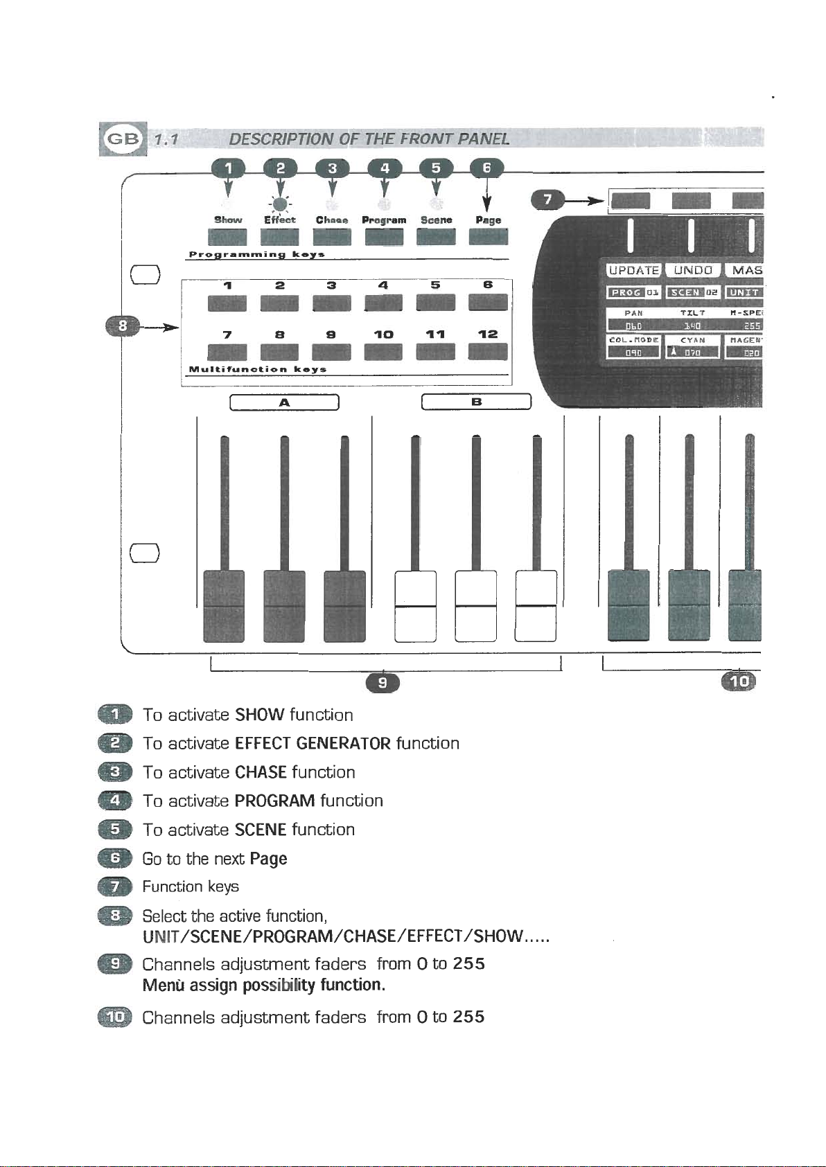
Programming
www.bluelight.at
keys
0
m
m
0
m
To activate
To activate
To activate
To activate
To activate
Go
to the next
Function
Select the active function,
UNIT/SCENE/PROGRAM/CHASE/EFFECT/SHOW..
Channels adjustment faders from 0 to
Menu
Channels adjustment faders from 0 to
assign possibility function.
SHOW
EFFECT GENERATOR
CHASE
PROGRAM
SCENE
keys
function
function
function
function
Page
function
. . .
255
255
Page 5
1
www.bluelight.at
Q,?S
CHASE
U----
'ER
Q)
m
m
m
m
m
m
m
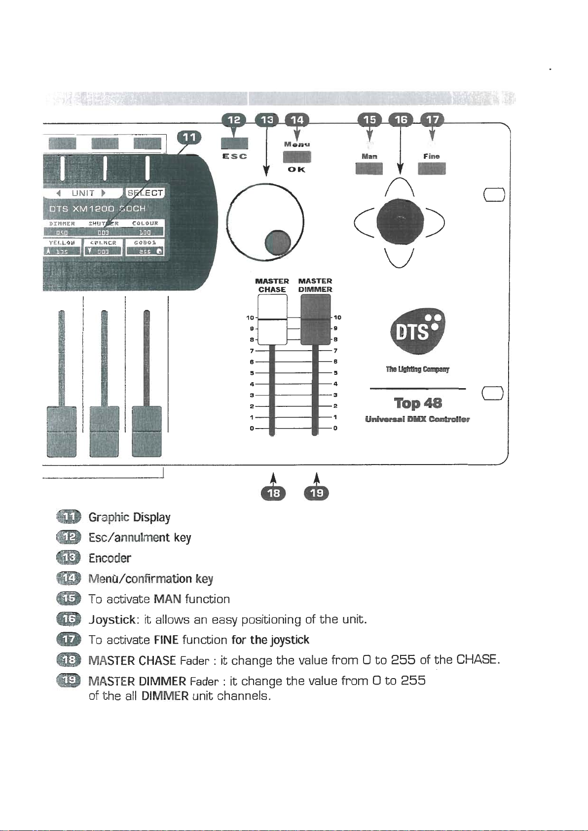
Graphic
Esdannulment key
Encoder
Men
To activate
Joystick:
To activate
MASTER CHASE
MASTER DIMMER
of the all
Display
Wconfirrnation
MAN
it allows an easy positioning of the unit.
FINE
DIMMER
function
function
Fader
Fader
key
for the joystick
:
it
change the value from 0 to
:
it
change the value from 0 to
unit channels.
255
255
of the
CHASE.
Page 6
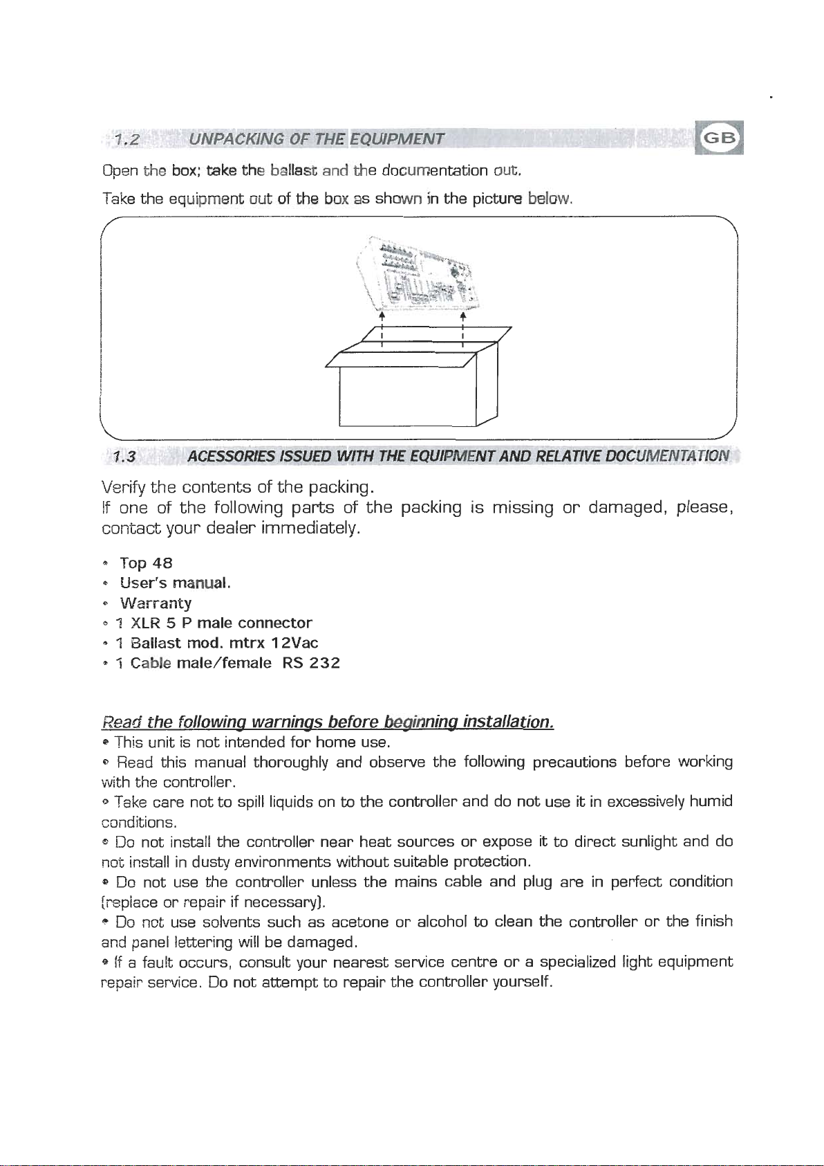
Open
www.bluelight.at
the
h;
tab
the
balk&
and
the documentation
owt.
Take the equipment
out
of
th
box
as shown in the pictwe
balm.
ACESSORIES ISSUED WlTH THE EQUIPMENT AND REf AWE DOCUMENTAT101
Verify
the contents of the packing.
If one of the following parts of the packing is missing or damaged, please,
your
contact
a
Top
48
User's manual.
Warranty
Q
1
XLR 5 P
'I
Ballast mod. mtrx 12Vac
Q
7
Cable
dealer immediately.
male connector
male/female
RS
232
Read
1~
0
the followina warninas before beainnina installation.
This unit is not intended for home use.
Read this manual thoroughly and observe the following precautions before working
with the controller.
to
Take care not to spill liquids on
the controller and do not use it in excessively humid
conditions.
Do
not install the controller near heat sources or expose it to direct sunlight and do
mt
install in dusty environments without suitable protection.
DO not use the controller unless the mains cable and plug are in perfect condition
frepiace or repair if necessary].
c
Do not use solvents such as acetone or alcohol
artd
panel lettering will be damaged.
to
clean the controller or the finish
if a fault occurs, consult your nearest service centre or a specialized light equipment
repair service. Do not attempt to repair the controller yourself.
Page 7
ttt
www.bluelight.at
t
t
m
@
m
Q
m
m
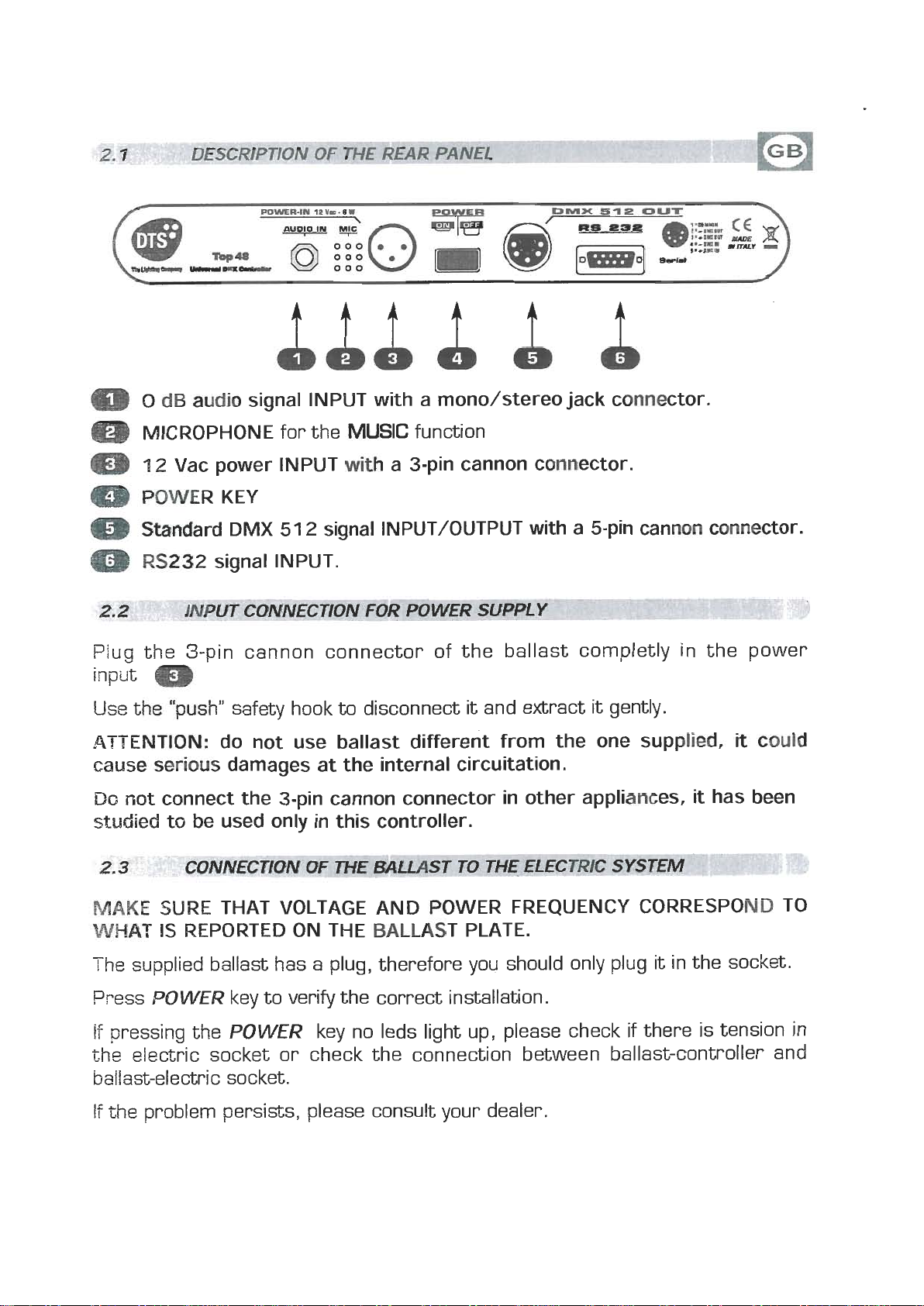
Plug the 3-pin cannon connector of the ballast completly in the power
input
Use
ATTENTION: do not use ballast different from the one supplied,
cause serious damages at the internal circuitation.
Do
studied
0
dB
arrdib
MICROPHONE
12
Vac power INPUT
POWER KEY
Standard
RS232
signal INPUT with a mono/stereo jack connector.
for the
DMX
signal INPUT.
UT CONNECTION FOR
51 2 signal INPUT/OUTPUT with a 5-pin cannon connector.
MUSIC
with
a 3-pin cannon connector.
---
function
POWER SUPPLY
--
p--
m
the "push" safety hook
not connect the 3-pin cannon connector in other appliances,
to
be
used only in this controller.
to
disconnect
it
and extract
it
gently.
-
it
it
has been
could
MAKE
WHAT
The
Press
if
pressing the
the
ballast-electric socket.
If
the
SURE THAT VOLTAGE AND POWER FREQUENCY CORRESPOND TO
IS
REPORTED ON THE BALLAST PLATE.
supplied ballast has a plug, therefore you should only plug it in the socket.
,DOWER
eleczric socket or check the connection between ballast-controller and
problem persists, please consult your dealer.
key to verify the correct installation.
POWER
key no leds light up, please check
if
there is tension in
Page 8
Make
www.bluelight.at
DMX
side
512
ofm
sure
you
are
signal
with
comac(or.
using
&Wed
conwmtors
e)
twisted
of
@od
cables
quav
slritgMs
and
for
crmmrctSon
Ehe
trammlsslon
as
shown
of
on
the
the
Plug the 5-pin
Use the "push" safety hook
ATTENTION: the shielded part of the cable must never be connected to the ground of
the electrical system as this cauM cause faults during the working of the controller
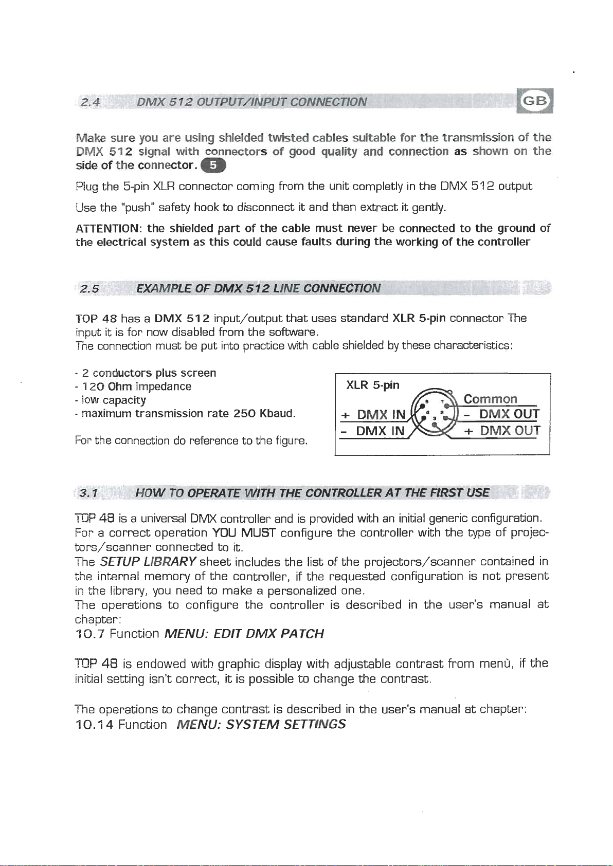
TOP
48
has a
it
input
The
-
2
-
1
-
IOW
-
maximum transmission rate 250 Kbaud.
Fm
is for now disabled from the software.
connection must be put into practice with cable shielded by these characteristics:
cwductors
20
Ohm impedance
capacity
the connection do reference to the figure.
XLR
connector coming from the unit completly in the
to
DMX
plus screen
51 2 input/output that uses standard
disconnect
it
and than extract
DMX
it
gently.
XLR
5-pin connector The
51 2 output
TOP
48
is a universal DMX controller and is provided
YOU
For a correct operation
brs/scanner connected to
The
SETUP LIBRARY
the internal memory of the controller, if the requested configuration is not present
ii7
the
library, you need
The operations to configure the controller is described in the user's manual at
chapter:
7
0.7
Function
TOP
48
is endowed with graphic display with adjustable contrast from menrj,
initial setting isn't correct,
-
r
he operations
7
0.1
4
Function
MENU: EDIT DMX PATCH
to
sheet includes the list of the projectors/scanner contained in
to
change contrast is described in the user's manual at chapter:
MENU:
MUST
it.
make a personalized one.
it
is possible to change the contrast.
SYSTEM SETTINGS
configure the controller with the
with
an initial generic configuration.
type
of projec-
if
the
Page 9
THIS
www.bluelight.at
FUNCTjON
PROGRAM,
ALLOWS
CHANGE
THE
TO
SEE
ONE
PARAMETERS
OF
THE
AND
EDITING,
48
SCENES
OF
THE
ACTIVE
Press
T~P,
function, and the display changes as shown in [Fig. 2)
The graphic display indicates the scene [highlighted] currently active
[Fig.
SCENE
SCENE
2)
if
an empty scene is selected, on the display appears
key
to
key led
activate
will
light up
SCENE
to
function [Fig.
indicate the activation of this
1
]
SCENE".
Press one of the
it
Pushes
For scenes
Note:
kn
again, the scene puts on out his end value.
Keep
Key to erase the active
the active
13+24/25+36/37+48
Master
1
+l
2
keys
to
select the scene.
use the
Dimmer
\
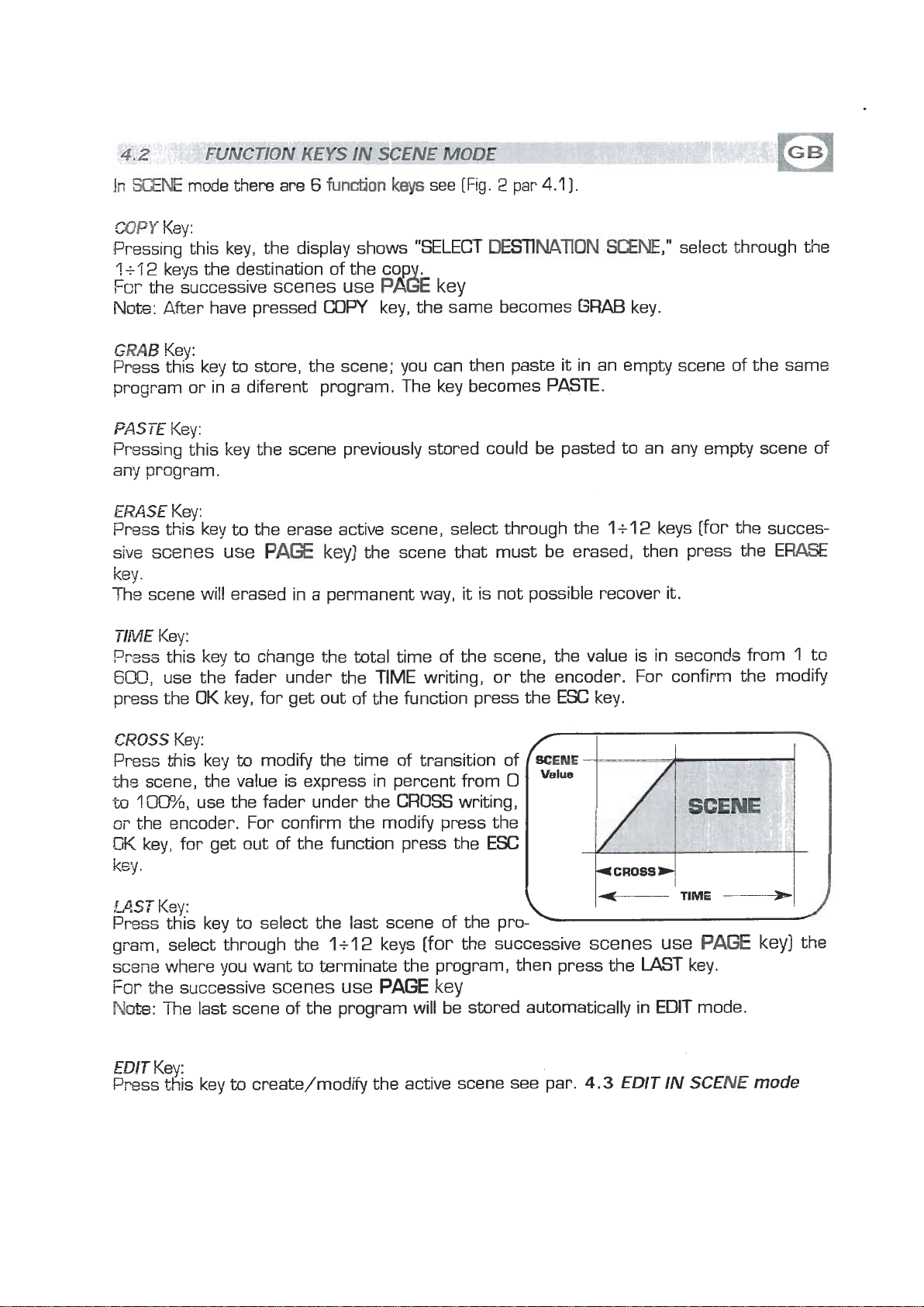
time Key to of the modify active the scene total Key
Faders
Function
to the maximum
Key to modify the time of
transition of the active
Kevs
PAGE
see Dar
key
(see
par
4.2
to
the last scene of the program
mark
\
f
h
4
COPY
&
I
ERASE
I
T
.L
E
ICROSSI
4
LAST
"FREE
6.1
I
I
W
1)
1
I
k
E~IT
and
pePco,nt
of
transltior;
the
scene number
-
indicates the total
time of the active
scene, in seconds
from
sition of the active scene
1
to
600
scene of the program
[indicates the time to1
transition in seconds
0
to
from
600
Page 10
h
www.bluelight.at
WNE
mde
t)ler~
m
6
funtidm
Jays
see [Fig. 2 par
4.1
1.
CUW
Pressing this key, the display shows "SELECT
ls'i
For
Note:
WE?
Press this key to store, the scene; you can then paste
program or in a diferent program. The key becomes
PASTE
Pressing this key the scene previously stored could be pasted to an any empty scene of
any
ERASE
Prsss this key to the erase active scene, select through the
sive
key.
The scene will erased in a permanent way,
TIME
Prsss this key to change the total time of the scene, the value is in seconds from
6@@,
press the
Key:
2
keys the destination of the
the successive
After have pressed
Key:
scenes use P& key
COW
mh&TION
key, the same becomes
SCENE,"
GRAB
it
in an empty scene of the same
key.
select through the
PASTE.
Key:
program.
Key:
1+12
scenes use
Key:
use the fader under the TIME writing, or the encoder. For confirm the modify
OK
PAGf
key, for get out of the function press the
key]
the scene that must be erased, then press the ERASE
it
is not possible recover it.
ESC
key.
keys
[for
the succes-
1
to
CROSS
Press this key
the
m
oi.
OK
key.
MST
Prsss th~s key to select the last scene of the program, select through the
scene where you want to terminate the program, then press the LAST key.
For
EDIT
Press this key
Key:
to
modify the time of transition of
scene, the value is express in percent from
1
[30%,
the encoder. For confirm the modify press the
key, for get out of the function press the
the successive
use the fader under the
Ksy;
1+12
scenes use
The last scene of the program will bi stored automatically in EDIT mode.
Key:
to
create/modify the active scene see par.
CROSS
keys
[for
PAGE
writing,
kev
0
ESC
the successive
scenes use
4.3
EDIT
IN
PA(3E
SCENE
key]
mode
the
Page 11
THIS
www.bluelight.at
VE
The
[Fig.
FUNCTION
PROGRAM.
graphic display indicates the scene [highlighted] currently active
2
par
4.1
ALLOWS
]
for create/modify it press the
TO
EDIT
ONE
OF
EDIT
THE
48
key [Fig.
SCENES
31.
OF
THE
ACTI-
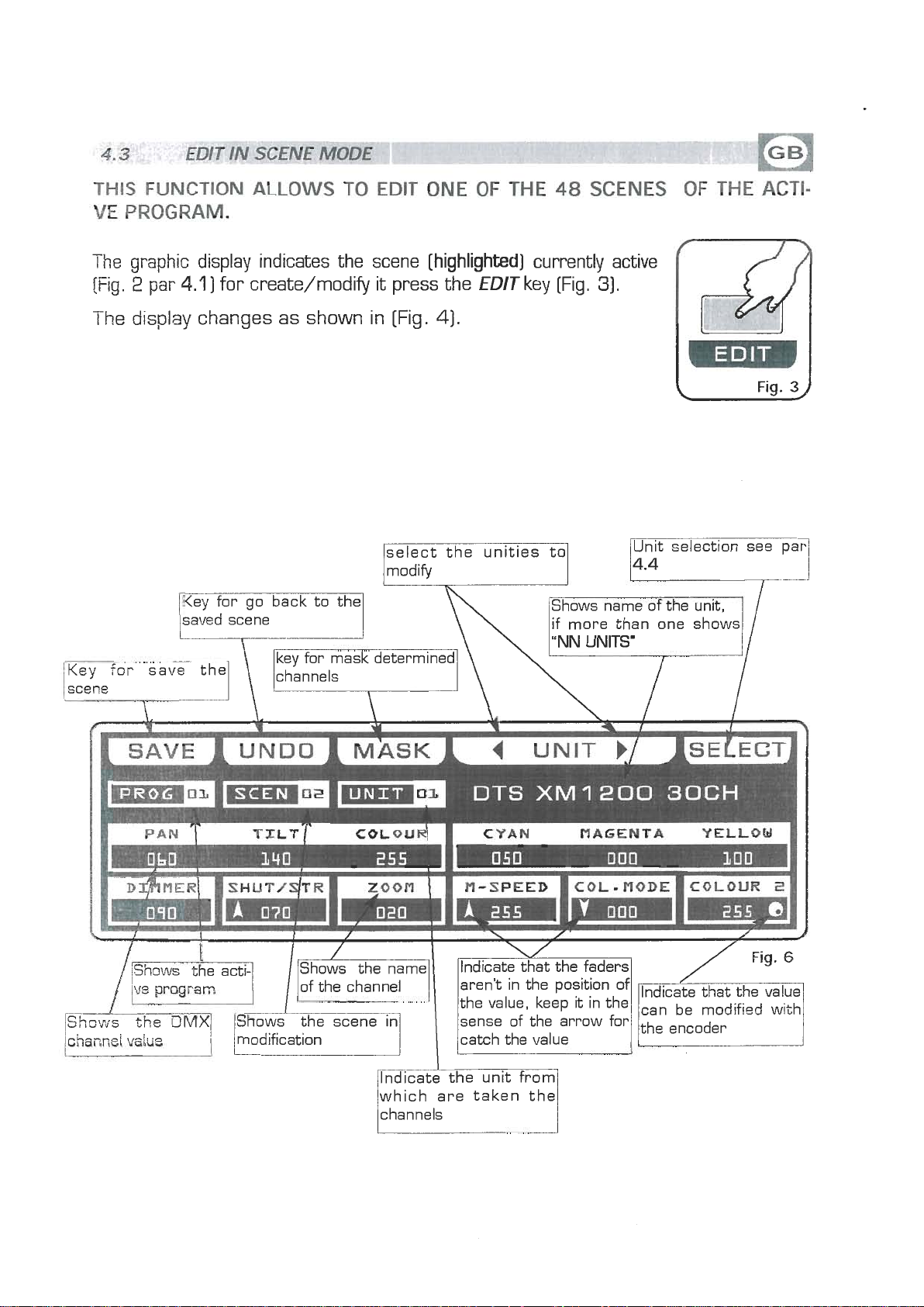
The display changes as shown in [Fig.
select the unities to
Jmodifyl
saved
scene
4).
h
Shows name of the unit,
if more than one shows
Fig.
3
4
channei
/[h
vdue
'vm
i
I
h\
Indicate the unit from
which are taken the
channels
DTS
Ilndicatext the faders,
XM
1200
30CH
/
Fig.6
Page 12
THIS
www.bluelight.at
FUNCTION
ALLOWS
TO
SELECT
ONE
PROGRAM.
To
activate the multiple selection of the unit press the
OR
MORE
SELECT
UNIT
ke)E
OF
THE
(m.
4
par
ACTIVE
4-31.
The display changes as shown in [Fig.
Press one of the
For successive units use the
Shows the
ve
pi-ogram
1
+l
2
keys to ativate one or more the unit.
P=
number of unit
key
SELECT
51.
UNITS-*-
MAR
ROBOCOLOR
/
IIX
Fig.
5
Shoals
/of the unit previou-
sly
internal library
see par.
i;
short name
ioaded from
10.6
ALL
Key:
Press this key to select all the units previously assign to the program,
possible select unit if not active in the program-see par.
Pressing this key the display shown
taken from the unit shown in the box
SOL0
Press this key to select onlv the unit shown in the box
selected withthe
the unit channels [es. no
box will indicate
vating SOLOthe
DONE
Pressing this key you confirm the selection of the unit see par.
Key:
Key:
ALL
key ail the
UNIT
UNIT
021,
02
02
lted unit see par
"NN
UNIT
48
unit, and we wants to change the value of
press twice the key
now the
SOLO
4.4
UNITS",
key unselect
the
1
5.2.
DMX
UNIT
02
of selection unit. The unit
all
that no unit loaded
from i~ternal
see par.
control channels will
the other unit, acti-
4.5.
10.6
it
isn't
,
if we have
iibi-ery
Page 13
EDIT
www.bluelight.at
U-
SCENE
MODE
-
THIS
TIES
Through the
the encoder.
FUNCTION
SELECTED
Pressing one of the
For successive channels use the
saved scene
ALLOWS
12
faders you regulate the value of corresponding channel see par
1
TO
MODIFY
+l
2
keys the correspondent channel can be modified with
TXfE
VALUE
PAGE
select the unities to
key
OF
THE
modify1
Shows name of the unit,
n
if more than one shows
CHANNELS
Unit selection see par
OF
THE
c
I
/
UNC
4.7
Key for save the
scene
f
=m
I
I
D~~MERI
1
DTS
SHUT/~TR
modification catch the value
m
Zoom
lndicate the unit from
which are taken the
channels
1
M-SPEED
aren't in the position of
sense of the arrow for
XM
1200
I
COL-
30CH
nODE
B
COLOUR
can be modified with
/the encoder
2
1
1
Page 14
S
www.bluelight.at
W€/ULPDAT;E
Press
The
see par
'thE!
UPDATE
4.1
key
:
SAW
key to save the free scene and go
key allow you to update the saved scene and go back to the scene function
to
the next free scene
U&DO
Prsssing this key you go back to the saved scene
MASK
Press this key
UN17
Press this keys to select the successive/precedent unit
SELECT
Pressing this key you go back to the unit selection see par
key:
key:
key:
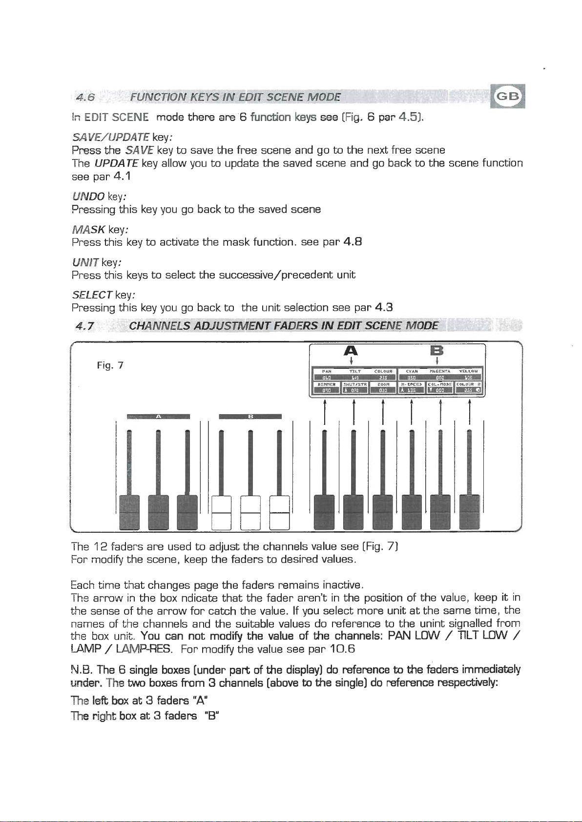
Fig.
key:
7
I
to
activate the mask function. see par
-
4.8
4.3
rrr~!!
-
l
he,
12
faders are used to adjust the channels value see [Fig.
For modify the scene, keep the faders to desired values.
Each time that changes page the faders remains inactive.
-.
Ins
arrow in the box ndicak that the fader aren't in the position of the value, keep it in
the sense of the arrow for catch the value. If you select more unit at the same time, the
names of the channels and the suitable values do reference to the unint signalled from
the box unit. You can not modify the value of the channels:
LAMP
N.B.
m&r,
The
The
/
W-RES.
The 6 single boxes [under part of the display] do reference
The
W
boxes from 3 channels [above
left
ba>c
at 3 faders
right
box
at 3 faders
For modify the value see par
"A"
"B"
iir
7
PAN
LOW / TlLT LOW
10.6
to
the
faders immediately
to
the single] do reference respectively:
/
Page 15
Using the joystick the
www.bluelight.at
PAN
and
ILT
channels
of
the scanner's mirror and and moving heads can
be adjusted [Fig
.8].
The joystick type is with central return, thanks
to the sophisticated software of management,
allows
it
an easy and exact positioning.
The mirror's speed movement could be chan-
ged through the
Every
speed
display
time
you press the Fine key the selected
it
is shows for 3 seconds on the graphic
[Fig.
Fine key
91.
0
Fine
With
mirror with a fixed speed, with
SPEED
01 /l0
the joystick moves the
SPEED PROP
joystick become proportional type, if you leave
the joystick in central position the mirror keeps
sti!l;
whereas the more you move
the centye the faster the mirror
Pressing twice the
The
Fine
key led will light up to indicate the activation of this function.
Fine
key joystick passes directly to the fine movement mode.
will
it
run.
away from
Useful function for control moving heads
Joystick movement change the
PAN/PAN LOW
channels.
and
TILT/TILT LOW
Fig.
8
output
I
I
PAN
I
I
DIrtnER
TIL"
I
S#UT/STR
DTS
I
ZOOPI
I
M-SPEED
XM1200
non
COL-FIQDE
30CH
l
COLOUR
r
2
1
Fig.
9
)I
1
Page 16
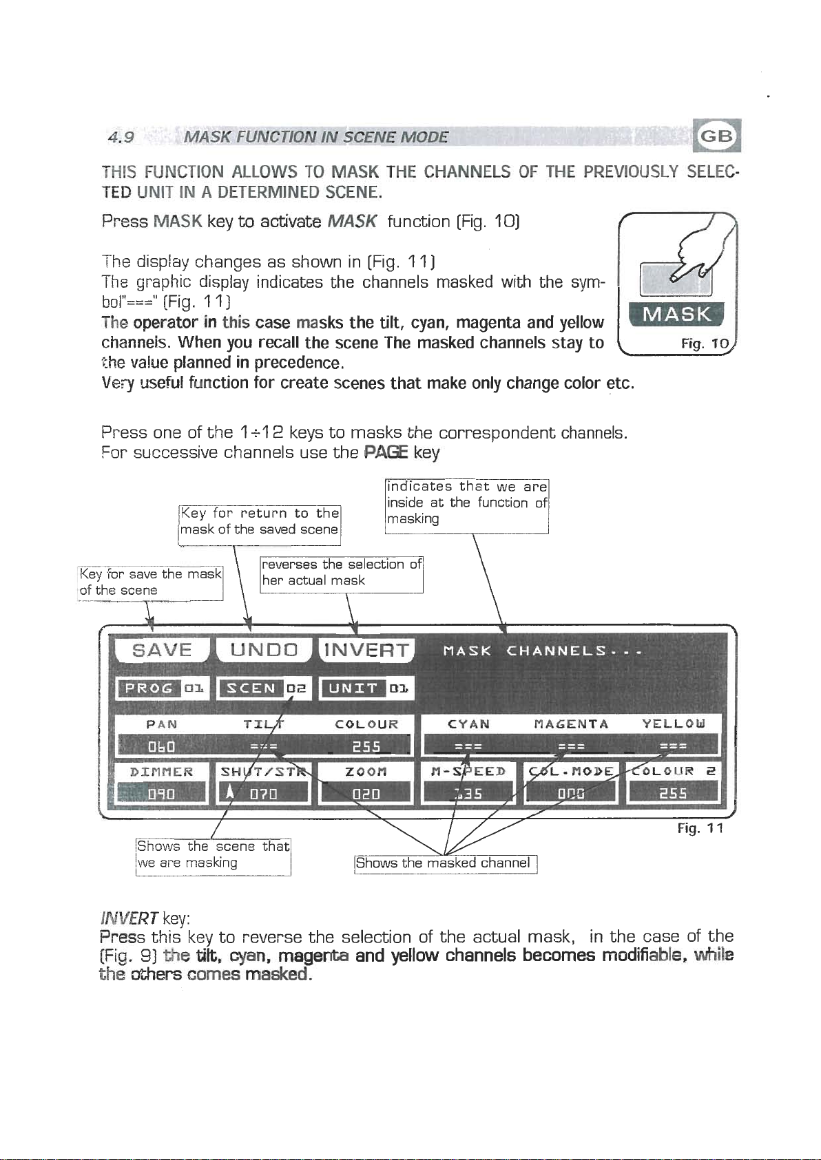
THIS
www.bluelight.at
TED
FUNCTION
UNIT
IN
A
UOWS
TO
DHERMINED
MASK
THE
SCENE,
CHANNELS
OF
THE
PREVIOUSLY
SELEC-
Press.
-
i
The
bol"==="
The operator
channeis. When you recall the scene The masked channels stay to
the
Very
Press one of the
For successive channels use the
MASK
keyts
aatjvate
W$K
function [Fig.
10)
he display changes as shown in [Fig. 11)
graphic display indicates the channels masked with the sym-
[Fig.
value planned in precedence.
useful function for create scenes that make only change color etc.
1 1
]
in
this case masks the
1
+l
2
mask
of
the
saved scene
tilt,
cyan, magenta and yellow
keys to masks the correspondent channels.
PAGE
key
lindicates that we are1
inside at the function
masking
of
(
I
DINflER
we ai-e masking
INVERT
key:
I
SH~TIST~
COLOUR
ZOOM
IShows the masked channel
I
CYAN
I
N-SPEED
MAGENTA
I
d~
-
I
YELLOW
HODEKOLOUR
2
Press this key to reverse the selection of the actual mask, in the case of the
[Fig.
31
the
tilt,
the
@hers
cyan,
comes
magenta and yellow channels becomes
masked.
modifiable.
while
Page 17
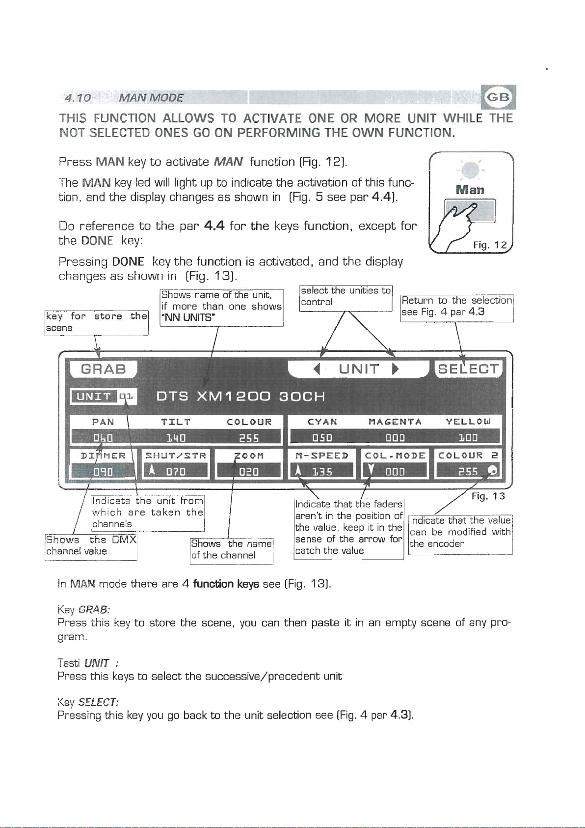
THIS FUNCTION
www.bluelight.at
MOT
SELECTED
ONES
AUOWS
GO
TO
ON
ACTIVATE
PERFORMING
ONE
THE
OR
OWN
MORE
FUNCTION.
UNIT
WHILE
WE
Press
The
MAN
MAN
key to activate
MUV
function [Fig.
key led will light up to indicate the activation of this func-
tion, and the display changes as shown in [Fig.
Do
reference to the par
the
M)NE
Pressing
key:
DONE
key the function is activated, and the display
changes as shown in [Fig.
Shows name of the unit,
if more than one shows
ey
for
store
f;
a
4.4
UNITS'
for the keys function, except for
131.
12).
5
see par
select the unties to
4.4).
Fig.
L
Return to the selection
12
\
/which are taken the
ichann~ls
In,W
Key
bess this key to store the scene, you can then paste
gram.
-
lasti
Press this keys to select the successive/precedent unit
Key
Pressing this key you go back
msde there are
GPAB:
UNIT
SELECT:
:
4
function keys
to
the unit selection see (Fig. 4 par
see [Fig.
/Indicate that the faders1
aren't in the position of
the value, keep it in the
sense of the arrow for
catch the
131.
1
vqlue
it
in an empty scene of any pro-
4.31.
Page 18
THIS
www.bluelight.at
FUNCTION
METERS
A
PRO-M
FRCM4
7
OF
TO
ALLOWS
THE
W.
IS
A
WAX
TO
SEQUENCE
48.
ACTIVATE
OF
$GENES
A
PROGRAM
(SlrAflC)
AND CWMGE
,
EXECUTE
IN
THE
PARA-
SEQUENCE
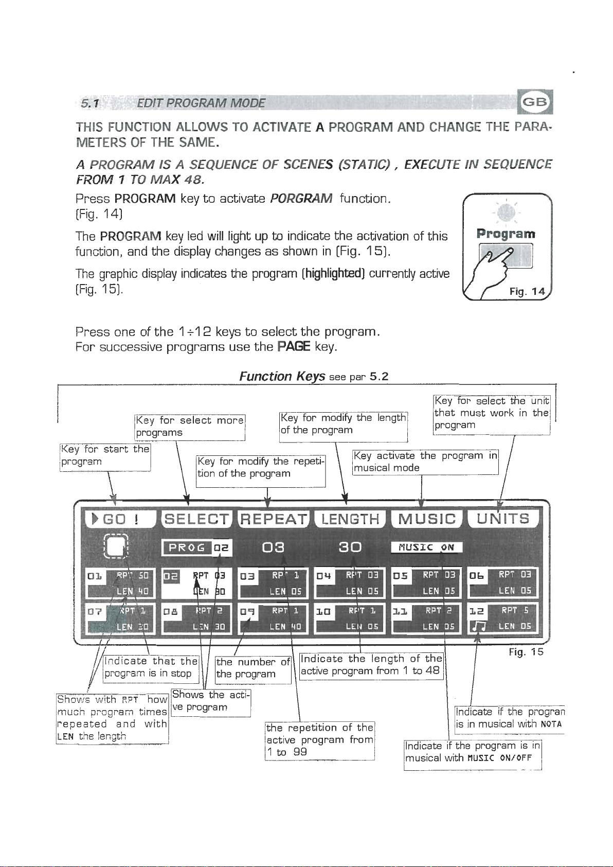
Press
(Fig.
The
PROGRAM
1
4)
PROGRAM
key led will light up
key to activate
PORGMM
to
indicate the activation of this
function.
function, and the display changes as shown in [Fig.
The graphic display indicates the program
(Fig.
1
5).
Press one of the
1
+l
2
keys to select the program.
For successive programs use the
Function
[highlighted]
PAGE
key.
Kevs
see
par
1
5).
currently active
5.2
py
for
select
the
unq
--
LEM
05
F
LEN
U5
LEM
05
Page 19
in
www.bluelight.at
EDIT
GO
Press this key
Note:
The key becomes
PROGRAM
key:
to
start the program.
Keep Master Dimmer Faders to the maximum (see par
mode
PAUSE
there
the display changes as shown in (Fig. 15 par
are
6
fundion
see
[Fig.
1
6.7
5
7)
pm
6.1
5.31
]
PAUSE
Press this key to stop the program in the current position, pressing the
it
recovers from the same position.
SELECT
Pressing this key
display changes as shown in [Fig. 14) see par
Press one of the
For successive programs use the
REPEA
Press this key to modify the number of repetitions of the program, the value is
in
der. For confirm the modify press the
the
LENGTH
Press this key to set how many scenes of the program will execute, the value is
in
der.
the
key:
key:
it
is possible the multiple selection of the programs. The
1
+l
2
keys to select the program.
T
key:
number from 1 to
ESC
key.
key:
n~lrnber from 1 to
For confirm the modify press the
ESC
key.
99
use the faders under the REPEATwriting, or the enco-
48
use the faders under the LENGTH writing, or the enco-
PAGE
5.3
key.
OK
key, for get out of the function press
OK
key, for get out of the function press
W
key
MUSIC
Pressing this key, and activating
scenes to time of music, in the box of the program and
play the display shows a note.
The internal music sensor has an automatic gain adjustment which allows to
have a signal level good for
The
swrces like Mixer, CD, Dat etc.
UMTS
Press this key to set what unit will be active in the program.
For successive units use the
key:
inpilt music signal is a OdB mono/stereo so it could be taken from sound
keys:
Top
PAGE
MUSE
48
working.
key.
ON,
the active program will change the
to
the side at symbol
Page 20

;ELECT
www.bluelight.at
Fcr
activate the multiple selection of the programs you must press the
SELECT
key [Fig. 1 6).
IN
PROGRAM
MODE
The display changes as shown in [Fig.
Press one of the
Foi. successive programs use the
key for select all the pro-
1
+l
2
keys to select more programs.
171
Key for set the program
lin
stop and get out of
l.
-
lgram
in
pause
1
71.
PAGE
Key for select only the
key.
I
Page 21

In
www.bluelight.at
PROGWM
mods
thee
are
6
fundon
Iceye
see
[Fig.
17
pm
53).
PdUSE
Press this key to stop the program in the current position, pressing the
It recovers from the same position.
STOP
Press
see [par
ALL
Press this key to select all the program from
SOLO
rress this key to select only the program shown in the box
selected with the
program [es. no
box
activating
SPEED
Pressing one of these two keys will
cf
the
To
key:
key:
this
key to stop the program with return to the function edit program
5.1)],
key:
key:
will indicate
key
program the value is in percent and varied from 10% at 500%.
the
value
pressing the
ALL
a),
PRO&
SOLOthe
:
100%.
W
key it start from the first scene.
1
to
48.
key all the
pfiss
02
PROG
the speed of execution is that planned in the scenes.
02
48
program, and we wants to selectd only the
twice the key
now the
SOLO
be
increased/decreases the speed of execution
02
of program selection. The prog
key unselect all the other program,
FROG,
if we have
00
key
Page 22

THIS
www.bluelight.at
TERS
W
(FROM
Press
The
function, and the display changes as shown in [Fig.
FUNCW
OF
THE
'CHASE
[S
TO
CHASE
CHASE
ALLOWS
TO
ACTIVATE
A
CHASE
SAME,
A
HAY
48
key to activate CHASEfunction (Fig. 18)
key led will light up to indicate the activation of this
OF
MAX).
LIGHTS,
IT
IS
W
SEQUENCE
AND
OF
18).
CHANGE
SKPS
THE
PARAME-
The graphic display indicates the chase (highlighted) currently active
[Fig.
1
9).
Press one of the 1 +l 2 keys to select the chase.
For successive chases use the
I
PAGE
Function
key
Keys
see par
6.2
l
Key for select more
/Key f~r start the
ichase
l.
Key for modify the repeti-
of the chase
Key activate the chase
in musical mode
7--
[
see par
,/
6.5
Fig.
14
/much
repeated and with
LEN
chess
the !enath
times
lVe
the repetition of the
active chase from
1
\
-ifthe
I
/in musical with
/Indicate 'if the chase
chase i
NUTA
4
Page 23

In
www.bluelight.at
EDtT
m
key:
Press
No@:
Re
&is key
Keep
key becomes
CHASE
mode
to
start the chase.
Master Dimmer Chase to the maximum see (par
them
PAUSE
are
8
fundun
the display changes as shown in [Fig. 21 par
ksys
Fe
[Fig.
'l
9
par
6.72)
&l]
8,3]
PAUSE
Press this key to stop the chase in the current position, pressing the key it
recovers from the same position.
SELECT
Pressing this key it is possible the multiple selection of the chases. The display
changes as shown in [Fig.
Press one of the 1 +l 2 keys to select the chase
For successive chase S use the
REPEA
P~ess this key to modify the number of repetitions of the chase
number from
der.
the
LENGTH
Press this key to set how many scenes of the chase will execute, the value is in
number from
der. For confirm the modify press the
the
key:
key:
19
par
6.31
PAGE
T
key:
1
to
99
use the faders under the
Fcr confirm the modify press the
ESC
key.
key:
1
to
48
use the faders under the
EX
key.
.
key.
,
the value is in
REPEAT
OK
key, for get out of the function press
LENGTH
OK
key, for get out of the function press
writing, or the enco-
writing, or the enco-
MUSE
Prr~ssing this key, and activating
scenes
the disp!ay shows a note.
Ths internal music sensor has an automatic gain adjustment which allows to
have
I
be
sources like Mixer, CD, Dat etc.
STEPS
9-ressing this key you go in the step mode see par
key:
MUSIC
to time of music, in the box of the chase and to the side at symbol play
a
signal level good for the
inpilt music signal is a OdB mono/stereo so it could be taken from sound
keys:
Top
48
ON,
the active chase will change the
working.
6.5
Page 24

THE
www.bluelight.at
For
SELECT
-
FUNCTION
activate the multiple selection of the chases you must press the
key (Fig.
I
he display changes as shown in [Fig.
AU-OWS
20).
TO
SELECT
A
SERIES
21
1.
OF
CHASE
Press one of the
For successive chases use the
key for select all the chases
Key for set the chase in
stop
l
i
1
+l
2
keys to select more chase.
PAGE
key.
Key for select only the
chase shows on
CHAS
I
Keys for increase/decrea;
se the speed of execution
of the chase
Fig.
20)
jlnciicate that the
//(lndicateY that the1
/~~l&~~~eactiv(~~pnumb~of
~STO~E--?~I
mtich
bepeated and with
I
chase
times1
\\
//
lactive 'chase from
\
Fig. 22
1
the chase Indicate if the chase
the chase
I
I
the speed of execution from
10%
L
n icate if the chase
-
I
in musical with
in musical with
IF--
to
500%
NQTA
NQTA
i
Page 25

In
www.bluelight.at
CHASE
mode
there
are
6
funobkrn
kqs
see
[Fig.
21
par
8.31.
PAUSE
Press this key to stop the chase in the current position, pressing the
recovers from the same position.
STOP
Press this key to stop the chase, pressing the
step.
AU
Press this key to select all the chase from 1 to
SOLO
Press
selected with the
chase [es. no
wiii
ting
SPEED
Pressing
cf
To
key:
key:
GO
by:
48.
key:
this key to select only the chase shown in the box
ALL
indicate
SOLOthe
key:
the
chase
the
vaiue
key all the
021,
CHkS
CHAS
ons of these two keys will be increased/decreases the speed of execution
the value is in percent and varied
100%.
press twice the key
02
now
02
the speed of execution is that planned in the scenes.
the
48
chase, and we wants to selectd only the
02
of chase selection. The chase box
SOLO
key unselect all the other chase, activa-
from
10%
key
at
it
start from the first
CHAS,
500%.
if we have
W
key it
Page 26

THIS
www.bluelight.at
FUNCTION
CHASE,
CHANGE
ALLOWS
THE
PARAMETERS
TO
SEE
ONE
AND
OF
THE
EDITING.
48
STEPS
OF
THE
ACTIW
Press
The display changes as shown in [Fig.
The
[Fig.
mPS".
Pyess one of the
Pushes
For
Note:
r~ev to
l
'
step
l..
STEPS
graphic display indicates the scene
231
if an empty step is selected, on the display appears
it
successive step use the
Keep
cow
the=
key to activate
1
+l
2
keys to select the step.
again, the step puts on out his end value.
Master Chase Faders to the maximum see (par
Key to erase the active
step
time of the active step
SEPS
PAGE
Function
I
function
[Fig.
23)
[highlighted]
key
Keys
I'
see par
\
22)
currently
"FREE
(
6.72)
6.6
Key to create or1
modify the active step
see par
the last step of the program
6.7
Fig.
,----
I
29
,
lactive chase
'and
trzcsitisn of the
p,.
indicate the step
\/nYmber\rI
indicates the time to transition of the active step
/
Fig-23
-
visualize the
active step
indicates the total time of
the active step, from
to
600
seconds
0,2
Page 27

In
www.bluelight.at
STEP
mode
there
are
6
fumtion
me
[Fig.
2
par
4.1
1.
COPY
Pressing this key on the display shows
the
For
Note:
GRAB
Press th~s key to store the step, you can then paste
chase or in a diferent chase. The key becomes
PASTE
Pressing this key the step previously stored could be pasted
chase.
ERASE
Pressing this key the active step will be erased, select through the
successive
EPASE
The
TIME
Press this key
600,
press the
Key:
'I
+l
2
keys the destination of the copy.
the successive
After have pressed
Key:
chases use
COW
"SELECT
PAGE
key, the same becomes
key
DESllNAlON
GRAB
it
in an empty step of the same
key.
SCENE,"
Pm.
Key:
to
an any empty step of any
Key:
chases use
key.
step will erased in a permanent way, it is not possible recover it.
Key:
to
change the total time of the scene, the value is in seconds from
use the fader under the
OK
key, for get out of the function press the
PAGE
key]
TIME
the step that must be erased, then press the
writing, or the encoder. For confirm the modify
ESC
key.
select through
1+12
keys [for the
0,2
to
CROSS
Press this key to modifie the time of transition of
the
to
or the encoder. For confirm the modlfy press the
OK
Key:
scene, the value is express in percent from
'i
W?,
key, for get out of the function press the
use the fader under the
(=ROSS
writing,
0
ESC
key.
LAST
Key:
Press this key to select the last step of the chase,
se!ect through the
where
Fm
Note:
EDf
Prass this key to create/modify the active step see par.
you want to terminate the chase, then press the
the successive
The
last step of the chase will be stored automatically in EDIT mode.
T
Key:
li12
keys [for the successive
chases use
PAGE
chases use
key
LAST
key.
6.7
EDIT IN STEP
TIME
Pm
key)
mode
the step
Page 28

THIS
www.bluelight.at
ACTIVE
The
23
FUNCTION
CHASE
graphic display indicates
par
6.5)
for create/modify
.
ALLOWS
the
TO
CREATE
step
(highlighted)
it
press the
OR
EDIT
MODIFY
currently active [Fig.
key
(Fig.
&NE
24).
OF
48
STEP
OF
The display changes as shown in
Pressing one of the
it
is high, to
For successive channels use the
\
255
Key tor go back to the
saved step
l
+l
2
keys the correspondent channel go
value if
it
is low.
Keys for select the successive/
precedent page
key for mask determined
channels
(Fig.
PAGE
25).
key
\\
,\\e~s
to
the 0 value if
y
3
pages
indicate the show4
,
l,/
/
/
DIMMERS
I
I
I
1
I
IShows the1
I
I
/~lndicate on which[\
I
/
l/
catch the value
001
+
1
012
,
Fia.
25
Page 29

SAVE
www.bluelight.at
hs5
key:
this key to save the step
UNDO:
Pvessing this key you go back
to
the saved step
MASK
Press this key to activate the mask function, see par
PAGE
Press this keys to select the successive/precedent page
3PG
Pressing
5.
key:
keys
keys:
:
6.10
:
this
will
jump
of
3
pages in 3 pages.
--
'&$INNELS ADJUSTMENT FADERS IN EDIT STEPS
MODE-^^'
The
12
faders are used to adjust the channels value see [Fig.
For modify the step , keep the faders to desired values.
Each time that changes page the faders remains inactive.
The
ari-ow
th~
sense
For
an
For successive channels use the
N.B.
The 6 single boxes [under part of the display] do reference
unrisr.
T~E
left
The
iiight
in
(71:
on-off
-.
I
na
iwo
box
box at 3 faders
71
the box ndicate that the fader aren't in the position of the value, keep it in
the arrow for catch the value.
chase type use the
boxes from 3 channels [above
at 3 faders
"A"
1
+l
PAGE
2
key
keys
to
the faders immediately
to
the single] do reference re~pe~vely:
"B"
Page 30

vIASK
www.bluelight.at
FUNCTION
IN
STEPS
MODE
THIS
Pressing
The display changes as shown
FUNCTION
MASltkey6he
ALLOWS
WK
70
MASK
function
in
[Fig.
THE
DIMMER
is
activated [Fig.
28)
CHANNELS
27)
The graphic display indicates the channels masked with the sym-
bol"==="
The
you
in
precedence.
Press one of the
For
[Fig.
28)
operator in
this
case
masks the
2,4,5
and 6 channels. When
recall the step The masked channels stay to the value planned
1
+l
2
keys to masks the correspondent channels.
successive channels use the
PAGE
key
IN
A
CY~~%
INVERT
Press
[Fig.
key:
this key to revers the selection of the actual mask, in the
93
the
masked.
2,4,5
and
HASK
-
DIMMERS
6
channels becomes modifiable, while the
CHANNELS---
001
+
01
'
2
case
others
r-,
i
9
of
the
mes
Page 31

TOP
www.bluelight.at
All
WMMER"
48
IS
ENDOWED
CHANNELS
wm
A
OF
GENERAL
THE
INfELLlGENT
CONTROL
LEVEL
UNITS.
OUTPUT,
OF
r
WASTER
MMIWER
The
Master Dimmer fader [Fig.
291
allows to adjust the bright
general intensity of the intelligent units,
unities
Keep
otdy
TOP
DIMMER
have
the
the dimmer channel).
fader always to the maximum loo%, keep to 0 value
for create a blackout.
48
IS
ENDOWED WITH A GENERAL CONTROL
CLASSIC CHANNELS.
(only
if
the connected
LEVEL
OUTPUT,
OF
Fig.
MASTER
CHASE
C
10
B
8
7
S
4
4
3
e
0
29
I
The Master Chase fader
?ai
intsfisity
For
have the bright intensity of chase/step at 100% keep the
of the
chase and relative step.
fader to the maximum, keep to
[Fig.
301
allows
0
to
adjust the bright gene
value only for create a
blackouz.
The
Master Chase fader could be used also for pu in output a step
like scene, see [par
Keep
step
the
fader to 0 value, select through the
we
want on output, then keep the fader to desired value.
6.51.
1+12
keys the
10.-
S
-
m
-
-
Fig.
2
-
8
7
8
5
4-
3-
2
1
0
-
30
Page 32

:FFECT
www.bluelight.at
MODE
THIS
THE
OF
Press
The
function, and the display changes as shown in [Fig.
The
attivo
Press one of the
For successive effect use the
FUNCTCON
ALLOWS
TO
ACTIVATE
RN
EFFECT
GENERATOR
PARAMETERS.
USING
THIS
NOTABLE EFFECT WITH
EFFECT
EFFECT
MODE
key to activate
key led will light up to indicate the activation of this
OF
OPERATION
17
IS POSSlBL
AN ONL Y COMMAND.
EFFECT
function [Fig. 181
E
311.
graphic display indicates the effect [highlighted) currently active
[Fig.
32).
1
+l
2
keys to select the effect.
PAGE
Function
Key for select more
1
key
Keys
selected scanner
see par
7.2
CREATE
lKey for select the unit)
/that must work in the1
AND
MODIFY
AlVIMATlONS
the active effect see
0'1
0
\
1
6d~dthat the theinumber of Indicate the applied effect
affect is in stop keffect
/
lrllf%:z
Shows with
much
re~sated effect f~r
L
RPT
how
effect times
I
the active1
active effect from
001
to
NORMAL
I
l
of the second row of the
selected scanner
\
999
\
/l
Fig.
PAN/TKT
32
Page 33

In
www.bluelight.at
EFFECT
W
key:
Press this key to start the effect.
The
key
m&
becomes PAUSEthe display changes as shown in [Fig.
there
are
6
fun&ian
ksye
see
[Fig.
32
par
7.11
34
par
7.3)
PAUSE
Press this key to stop the effect in the current position, pressing the
recovers from the same position.
SELECT
Pressing this key it is possible the multiple selection of the effect. The display
changes
Fress one of the
For successive effects use the
RE?s"A
Press this key to modify the number of repetitions of the effect, the value is in
number from
encoder. For confirm the modify press the
press
2ndRO
Foi. faced or disposed on more rows scanners.
Pi-ess this key to modify the effect of the second half of the selected scanner.
-
!
he rnoclalities are:
NORMAL: No modification.
NO
!KV
dNV
fNt%
Use the fader under
press the
key:
key:
as shown in [Fig.
1
+l
P
key:
001
the
ESC
W
key:
DELAY: Keep the first scanner in phase, if there are DELAY.
PAN:
TbLT: Reverses the movement of the mirror Y axis
ROT: Reverses the direction of the shape execution.
Reverses the movement of the mirror X axis
to
key.
OK key, for get out of the function press the
34)
see par
2
keys to select more effect .
PAGE
999
use the faders under the
7.3
key.
OK
2ndROW
write or the encoder. For confirm the modify
REPEAT
key, for get out of the function
ESC
key.
GO
key it
writing, or the
EDIT
Key:
Press this key to create/modify the active effect, see par
U?WS
Press this key to set what unit will be active in the effect.
For successive units use the
keys
7.5.
:
PAGE
key.
Page 34

THIS
www.bluelight.at
IN
For
SELECT
The
FUNCTION
ALLOWS
TO
SELECT
A
RANGE
OF
SUCCESSION
ectivate the multiple selection of the effects you must press the
key (Fig. 33).
dis~lay changes as shown in [Fig.
34).
EFFECTS
EXECUTAE3LE
Press
For successive effects use the
one of the
/key
for
1
+l
2
select
keys to select more effect.
all
the1
PAGE
key.
Page 35

In
www.bluelight.at
EFFECT
GO
key:
Press
The
this key
ksy becomes
made
there
to
start the effect.
PAUSE
am
B
fudm
keys
see
[Fig.
34
par
7.31.
PAUSE
Press
yecovers from the same position.
STOP
Press
pressing the
ALL
Press this key to select all the effect from 1 to
SOL8
Press
sel~cted with the
effect. [es.
indicate
SOLBthe EFFT
ZOOM
Press
cution: the value is express in percent and varied from
value the shape stop.
key:
this key to stop the effect in the current position, pressing the
key:
$his key to stop the effect, return to the
GO
key
it
start
kq:
key:
this key to select only the effect shown in the box EFFT, if we have
ALL
no
021,
EFFT
press twice the key
02
now the
again.
key all the
SOLO
48
effect, and we wants to selectd only the
02
of effect selection. The effect box will
key unselect all the other chase, activating
EFFECT
48.
U2
key:
this key for increase/decrease the percent of zoom of the shape in exe-
function see [par
000%
to
200%.
GO
To
key it
7.11,
000
WEED
Press this key
is
key:
to
increase/decrease the speed of execution of the chase, the value
in
percent and varied from 10% at 500%.
Page 36

rDIT
www.bluelight.at
EFFECT
MODE
THIS
The
[Fig.
The
Press
Press
FUNCTlQN
WOWS
TO
EDIT
ONE
OF
48
EFFECTS
graphic display indicates the effect [highlighted] currently active
32
par 7.11 for create/modify it press the
display changes as shown in
one
of
the l s6
one
of
the
IKey to set the shape
keys to select the effect on the
7+12
keys to select the effect on the
[Fig.
and the direction of the
shape
361.
EDIT
key [Fig. 351.
PAN
I
TILT
channel
channel
of the shape between!
an unit and the
next
L
,/.L
ithe efkct in editing
type of shape
shows the dimension of the shape
-the
of the shape
of the shape
Page 37

In
www.bluelight.at
EDIT
EFFECT
mode
there
are
6
funclion
see
[Fig.
36
par
7.51.
SAVE
Press this key to save the
effect
SHAPE
Press this key for select the
shapes, that are:
Circle,
Vertex, and Zigzag.
The
operator could change correspond to:
Press
"
size
'l
RPM
Pxss this key to change the
speed
shape [from -60
key:
key:
Hola, Ladder, Square,
parameters that the
t
is key to change the
of
the shape [from 1 to
281
key:
and direction of the
to
+60)
Wave'
S
forms of
the
SHAPE
PHASE
Press this key to change the
the
[from
DELAY
Press this key to change the
day
ert
a
key:
start corner of the shape
O
to
359).
key:
of the shape between
unit and the next
3591.
[from
0
Square
Vertex
Page 38

THIS
www.bluelight.at
FUNCTION
ALLOWS
TO
ACTIVATE A SHOW
AND
MODIW
THE
PARAMETERS
Press
The
f~nstion, and the display changes as shown in [Fig.
-.
!
i;e
[Fig.
SHOW
SHOW
graphic display indicates the show [highlighted] currently active
key to activate
key led will light up to indicate the activation of this
SHOW
function [Fig. 371
381.
38).
Function
Keys
see
par
8.2
Fig.
37
active SHOW
I
the SHOW
Fig.
38
Page 39

GO
www.bluelight.at
key:
Press this key to start the show.
The key becomes
PAUSE
the display changes as shown in [Fig.
40
par
8.31
PAUSE
Press this key to stop the show in the current position, pressing the
recovers from the same position.
EDIT
It
allows to modify the parameters of the show see par
PAGE
Pressing one of these two keys you go
SPEED
Pressing one of these two keys you increase/decrease the speed of the show the
value is in percent and varied from
-
I
o
key:
key:
key:
to
the following /next page
key:
10%
to
500%.
the 100% value the speed is the original.
8.4.
W
key
it
Page 40

THIS
www.bluelight.at
FUNCTION
EXECUTES
AND:
VISUALIZES
THE
STATE
OF
THE
SHOW
The graphic display indicates the step [highlighted] currently active[fig.
38
par
8.1
)
for execute it press the
The display changes as shown in [Fig.
Press one of the 1 +l 2 keys to select the show.
For successive show use the
Key for stop the
SHOW1
GO.'
PAGE
key [Fig.
401.
key
39).
Key for increase/decrease
the weed of execution
fT
L
p
Fig.
39
of
show in execution
of the
Effect
Chase
Program 12, 06, 09, 05
SHOW:
05 and
01
04
Page 41

THIS
www.bluelight.at
The
[Fig.
[Fig.
-
FUMC?7ON
graphic display indicates the show [highlighted) currently active
38
par
ALLOWS
8.1)
for create/modify it press the
TO
CREATE
OR
MQDIFY
EDlT
ONE
key
41).
I
he
display changes as shown in [Fig. 42).
QF
BB
SHOW
EDlT
Fig.
C
41
Press one of the
scr
.
visualize the show
in modification
Key for return to the
1
+l
2
keys to select one of 4 effect/chase/program proces-
shows how much
effect/chase/program are
active in the processor
effect/chase/program
visualize the processor processor
selected in white
I
CHASE
Key for select which
effect/chase/program processor will be ective in the
show vedi par
8.5
Fig.
42
[
EFFECT
processor zone
[
1
I
CHASE
processor zone
1
PROGRAM
I
processor
zone
I
Page 42

THIS
www.bluelight.at
GRAMS
The graphic display indicates the effect/chase/program processor [highlighted] currently active [Fig.
effett/program/chase active in the varieties processor press
the
The display changes as shown in [Fig. 44a/44b/44c].
Press one of the
For successive effect/program/chase use the
FUNCTION
TM
SELECT
key [Fig.
ALLOWS
COMPOSE
1
+l
431.
2
THE
keys
TO
SELECT A SERIES
OF
LFFECT/CHASE/PRO-
SHOW
42
par
8.41
to select the
to
select more effect/program/chase.c
PAGE
key.
Rg.
43
m
EFFECT SELECTION
SELECT EFFECTS...
*
1-a
OLAlCIRC
CI-lASE SELECTION
SELECT
*
CIRC/SQR
CIRC/CIRC
CHASES---
01
I
EFFECTS
l
-
RTlVERT
1
*
Fig.
,.
.
.
.
Fig.
44.3
'a
44b
W-
LEN
30
PROGRAM
SELECT
LEN
W
SELECTION
PROGRAMS---
LEN
U5
LEA
US
Fig.
44c
Page 43

A
www.bluelight.at
Pm
To create/modify a program fdlow all steps listed below:
I]
If Top
21
Press
[the
31
Press
[only one program
For successive program use the
41
Press the
work in the program. Confirm with the
51
Press
[the
61
Press one of the
For successive scenes use the
is a range of scenes [max
48
is switched off, switch
Program
Program
1
+l
2
key to activate the
led key will light up].
keys to select only the program that you want to modify.
MghlrghW].
UNITS
Scene
Scene
led key will light up].
key and select through the
key to activate the
1
+l
2
keys
48)
performed in succession.
it
on pressing
PROGRAM
Pm
SCENE
to
select the scene that we want
PAGE
key
DONE
function.
key
POWER
function.
1
+l
2
key
keys the units that must
key.
to
create/modify.
71
Press the
8) Modify the position with the joystick and the sets of the channels with the
relative faders, press
91
When the scene has been completed,
1
?
]
Now Top
121
When the creation of the scenes has been finished press
come back to the
[the
?
3)
Finally you must press the
EDIT
48
is in the next scene repeat again the 7 and 8 steps.
Program
key to create/modify the selected scene.
UNIT
PROGRAM
led key will light up].
key for next/precedent unit.
it
can be stored through the
function.
GO
key to execute the program.
SAVE
Program
key.
key to
-
I
he
program is complete; to create/modify others repeat again' all the above
steps.
Page 44

A
www.bluelight.at
To
create/modify a program follow all steps listed
is
a
ply
of
lights, it is a sequence of steps
[M
'l
hdw:
to
48
max].
'i] If Top
21
Press
[the
31
Press
[only one chase highlighted].
For successive chase use the
41
Press
51
Press one of the
For successive steps use the
7
Press the
91
Modify the value of the channels through the 12 relative faders or the
For next channels use the
10;
When the step is completed it can be stored through the
1
'l
] Now Top
step or copy the step already done in another one.
48
is switched off, switch it on pressing
Chase
Chase
1
+l
2
STEPS
EDIT
48
POWER
key to activate the
led key will light up].
keys to select only the chase that you want to modify.
key to activate the
1
+l
2 keys to select the step that we want
key to create/modify the selected step.
PAGE
is again in the
STEPS
CHASE
P=
PAGE
key
STEPS
key
key
function in order that you can select another
function.
function
key.
to
create/modify.
'l
+'i
2
SAVE
key.
keys.
121
When the creation of the steps has been finished press
come back to the
[the
Chase
131
Finally you must press the
led key will light up].
CHASE
function.
GO
key to execute the chase.
Chase
key to
-
r
he chase is complete; to create/modify others repeat again all the above
steps.
Page 45

CREATIOlV
www.bluelight.at
Top
48
is endowed with pre-programmed plays movement, [modifiable] dedica-
ted to the scanner and moving-head.
With this function it's possible to create animations of notable effect.
The available plays are:
Circle, Hola, Ladder, Square, Vertex, and Zigzag.
The parameters that the operator could vary correspond to:
OF
AN
EFFECT
SHAPE:
,GEE:
RPM:
PHASE:
DELAY:
The
combinations.
l
]If Top
21
Press
[the
31
Press one of the
For successive effect use the
4j
Press the
51
Press one of the
Press one of the
Shape
Dimension of the shape [from 1 to
Speed and direction of the shape [ from -60 to +60]
Corner of departure of the shape [from 0 to
Delay of execution of the shape between an unit and the next [from 0 to 3591.
parameters are independent for
48
is switched off, switch it on pressing
Effect
Effect
key to activate the
led key will light up].
1
+l
2
keys
EDIT
key to create/modify the selected effect.
1
+6
keys to select the effect on the
7+12
keys to select the effect on the
1281
3591.
PAN
to
select the effect that we want to create/modify.
PAGE
and
TILT,
EFFECT GENERATOR
key
it is possible an infinity of
POWER
PAN
key
function.
channel
TILT
channel
Sj
Modify the parameters of the effect through the
PHASE
-
/]
Once modified the parameters, we can be store the modifications through
SAVE
the
8)
Now Top
91
Press the
'l
Cl] Finally you must press the
The
effect is complete; to create/modify others repeat again all the above
steps.
and
DELAY
key.
48
is again in the
UNITS
SHAPE, SIZE, RPM,
keys.
EFFECT
key to check which unit must perform the effect.
GO
function.
key to execute the effect.
Page 46

-
www.bluelight.at
!
his operative mode, allows to perform, at the same time,
of program
'l
]
!f Top
2)
Making sure of have program,chase ed effect [see par 9.1 /9.2/9.3]
+
4
sequences of chase
48
is switched off, switch it on pressing
+
4
sequences of effect
PQWER
up
to 4 sequences
key.
3) Press
[the
4)
Press
[only one show
For successive show use the
5)
Press the
S)
Select through the
want to configure.
7
Press the
that must work in the processor.
8)
Press the
9)
Through the
?
Oj When the modify is complete, we can return in the SHOW function
through the
Show
Show
1
+l
key to activate the SHDWfunction.
led key will light up].
2
keys to select only the show that you want to modify.
higMishEed].
EDtT
SELECT
Done
key to create/modify the selected show.
key to confirm the selection
On/Off
Back
or
P-
1
+l
2
keys the effett/chase/program processor that we
key for select which effett/chase/program
key switch it
Esc
key.
key
on&
the boxes
A,B,C,D
of processor.
1 1)
Now Top
'l
3)
Finally you must press the
The show is complete; to create/modify others repeat again all the above
steps.
48
is again in the
SHOW
GO
function in order that you can select another
key to execute the show.
one
Page 47

70.7
www.bluelight.at
THIS
UNIT
Press
The display changes as shown in [Fig.
As
soon as this function is activated, the display shows the
first function available..
MENU
FUNCTION ACTIVATES SOME SPECIAL FUNCTIONS FOR THE CONTROL OF THE
AND
THE SETTING OF THE CONTROLLER.
Menu
FUNC77ON
key to activate
MENU
function. [Fig.
45)
46)
m
Menu
Through the encoder it is possible select the
To activate the selected function press the same
T
Q,
2
-
r
his
fmction allows to black-out all the unit connected.
$:ass
The
display changes as shown in [Fig.
MENU:
DONE
BLACKOUT
or
ESC
key to start again the normal working.
46).
MENU
functions available.
[OK)
key.
Fig.
46
Pressing the KEEP key the Blackout comes kept up
gram
or
a scene.
to
when you call a pro-
Fig.
I
46
Page 48

AVAILABE
www.bluelight.at
ONLY
AFTER
THE
ACTNAION
OF
THE
MENU
FUNCTIONS
[v,par,
l
0.
I
)
ALLOWS
(only
NOTE:
need to wait that
The
display changes as shown in [Fig.
At the activation of the function the units are all selected.
Press one of the
For successive unit use the
TO
TURN
IF
the selected unit are predisposed for this function).
If
the lamp is "discharge" type and
ON
it
gets
1
+l
**
/
TURN
cold.
2
keys to select the unit.
03
OFF
THE
47).
PM
key
if
are more of one it
UNITS
LAMP
**
OF
ONE
OR
it
is still hot, before its lighting you
M6RE
UNIT.
will
ALL
key:
Press this key to select all the unit from
SOLO
Press this key to select only the unit shown in the box UNIT, if we have seiected
with the
press twice the key
the
OFF
?ressing one of these two keys will be turn on/turn off the lamp of the selected
For
key:
SOLO
-
ON
get out of the function press the
1
to
ALL
key all the
key unselect all the other unit, activating
keys:
48
unit, and we wants to selectd only the unit [es.
02
of unit selection. The unit box will indicate
ESC
key.
48.
imparted command
SOLO
the UNIT
UNIT
02
ri3
D2
921,
now
tlrtlt.
Page 49

AWLABLE
www.bluelight.at
DNLY
AFTER
'ktE
ACTIVATION
OF
THE
MENU
FUNCTIONS
&.par,
l#,
l
3
ALLOWS
(only
?his
don't
The display changes as shown in [Fig. 481.
At the activation of the function the units are all selected.
Press one of the
For successive unit use the
TO
RESET
if
the selected unit are predisposed for this function).
function must be performed when the unit lose synchronization or they
perform the commands of the controller in a correct way.
unit shown on
1
+l
ONE
OR
IWORE
2
keys to select the unit.
PAGE
UNIT
UM.
key
if
are more of one
Shows
"NN
UNITS'
it
Key
for reset
T
7
MAR
ROBDCOLOR
IIX
the
un
Fig.
Ail
key:
Press this key to select
SOLO
Press this key to select only the unit shown in the box UNIT, if we have seiected
with
press twice the key
the
RESET
Press this key to reset the selected unit
For get out of the function press the
key:
the
ALL
SOLO
key:
key all the
key unselect all the other unit, activating
all
the unit from 1 to
48
unit, and we wants to selectd only the unit [es. no
02
of unit selection. The unit box will indicate UNIT
ESC
key
48.
SOLO
the UNIT
02
02
48
021,
now
Page 50

AVAItA8LE
www.bluelight.at
mfs
function is wd when we have the need to control a determined chan-
nel
(of all the connected units), always and only from a faders.
The display changes as shown in [Fig.
ONW
AFER
WE
ACTlVAnON
OF
491.
THE
MENU
FUNCTJQNS
&.par.
10.7
1
When yuo keep the fader to zero value the display shows the writing
from assignments, the channels come loaded from the controller in an original way.
Move the fader of the section
Through the encoder or the
iorward/back for a more precise search.
-
r
o
assign the channel press the
For
get out of the function press the
Key
to
channel
see
sat-
assign the
in
live way
10.6
Shows the 3 faders of the
A
section
"A"
1/12
DONE
or
"
B,"
to assign a memorized channel.
keys directly above at the faders you can roll
or
OK
key
ESC
key.
3
IShows the
faders of the]
*free*,
v
free
can
be modified with the
:encoder
Fig.
49
Page 51

AfLOWS
www.bluelight.at
This
faders or to control a determined
The
Ths functions that the operator could assign through the relative keys correspond to:
TO
ASSIGN
function is used to control the performance of programs, chase, effects through
display changes as shown in
DIRECT
CO-
DMX
[Fig.
FUNCTIONS
channel.
501.
AT
72
FADERS.
SHW SPEED:
PR6
SPEED:
CHS SPEED:
EFT
SPEED:
EFT
ZOOM:
DMX
FREE:
If the function is of
!f
encoder you select if the action of the faders is valid for all the programs/chase/effects
or
To
For get out of the function press the
NOTE:
SCENE/STEPS/PROG/GO! PROG/CHASE/GO! CHASE/EFFECT/GO! EFFECT/SHOW/GO! SHOW
FQR
WIVG
007:
No function associate
the function is
in
the case of Show performance the 4 possible
assign
THIS FUNCTION IS ACTIVE IN
EULL
Show,
Performance Speed of the
Performance Speed of the
Performance Speed of the
Performance Speed of the
Dimension of the
Direct control of the channel
DMX
type, through the faders or the encoder you select the channel.
SPEED or ZOOM [SHW SPEED excluded],
Effect
the function faders press the
MODE:
ESC
Show
Program
Chase
Effect
DONE
key
or
[A
OK
through the faders or the
B,
C,
D]
key
THE DISPLA Y THAT SHOWS THE VALUES, PRESS THE CORRESPON-
Effect, Chase, Program KEY (FIXED LED)
A
section
\\W
Fws
the 3 faders immediately under thedisplay
Fig.
5G
Page 52

AVA! LAB LE ONLY AFTER
www.bluelight.at
ME
ACTIVATON
-
-
--
OF
THE
MENU
FUNCTIONS
[v.par.
l
U.
l]
&.LOWS
ALL@WS
&LOWS
@€SET VALUE, BLACKOUT VALUE, HARD/SOFT CROSS) IT ALSO ALLOWS
GN
MP CONTROL).
ATTENTION
EFFECTED IN AN APPROPRIATE WAY, PREVENTS THE CONNECTED UNIT TO
c"0RRfCTL Y.
-
I
he display changes as shown in [Fig.
Press one of the
For
for copy the unit
-
7-
7'0
L
WA
TO
PATCH
TO
MODIFY
SPECIAL FUNCTIONS TO THE CHANNEL (PAN/TILT,PAN LOW/TILT
!
MODIFICATION OF THE EDIT DMX PATCH PARAMETERS,
successive unit use the
Key for modify the
parameters of the unit
Key to load setup
from library
COMF'LEE
WX
/
THE
1
+l
2
keys to select the unit.
SW
AU
NAME OF EACH CHANNEL AND ITS
PAE
FROM
TOMiQ
key
Shows name of the unit
LCBRCVZY
fC / MAMUAL
511.
Key for erase
AND
.
STORE
lKey for manual1
Key for automatic
'i-+]
fT
!M
PARAMETERS
MEMORY.
TO
ASS*
LOW,
jF
MOT
WORK
Shows
short name
LZ7
Shows the number
of the unit
I
SUPER
tion to set on the [dip-
switch] of the unit.
Page 53

In
www.bluelight.at
EDIT
DMX
PATCH
made
there
are
6
fundon
kep
see
[Fig.
51
par
10.7).
COPY
Pressing this key on the display shows
1
For
LOAD
Press this key to load compleate setup from library, see par 10.9.
Eh317
Press this key
ERASE
Press this key to the erase active unit, select through the
units use
The unit will erased in a permanent way,
PA
Press this key to modify start address of the unit, use the fader under
the encoder. For confirm the modify press the
the
Key:
+l
2
keys the destination of the copy.
the successive
Key:
Key:
Key:
PAGE
TCH
Key:
ESC
key.
unit use
to
modify the name of each channel and its parameters, see par
key] the unit that must be erased, then press the
PAGE
"
SELECT DESTlNATlON
key
it
is not possible recover it.
OK
key, for get out of the function press
UNIT", select through the
1
+l
2
keys [for the successive
ERASE
10.1
key.
PATCH
1.
write or
-
I
up
48
will calculate the last channel for that unit and under
shows the configuration
NOTE:
STANDARD
CORRECT
UMs"7
The on position of the dip-switch is with white box appears aloft.
When
ped
AUTO
Press this key to modify start address in automatic way, select through the
the unit of start
For
Now
For
ANY
BUILDERS
SET
TO
OPERATION,
START = 728
you exit from the men0 the software controls if there are unit with equal or overlap-
addresses, the display shows a message of error "PATCH OVERLAY AT UNIT.
Key:
,
then press the
the successive
from the unit of start
the successive
to
set on the dip-switch of the unit.
ADOPT
"0"
FOR
YOU
->
TOP
unit use
to
unit use
THE CONFIGURATIOlU
INDICATE
DMX
CHANNEL
MUST BE ADDED
48
ADDRESS
AUTO
PAGE
the last unit the addresses have been assigned.
PAGE
key.
key
key
=
729
OF
+V"
(EXAMPLE
"7.
PATCH
THE
DIPSMnTCH
"
IN THIS
write you can
CASE
ADDRESS
1
"
+l
LIKE
FOR
2
keys
A
OF
Page 54

AVAILABLE
www.bluelight.at
MVLY
ARER
THE
ACTIVATION
OF
THE
MENU
FUW[=TIONS
-
[v.par.10.7]
ALLOWS
Press
The display changes as shown in [Fig.
the
TO
LgClD
LOAD
A
COMPLETE
key
to load setup from library [Fig.
SETUP
F-
53).
The display shows the first unit in the library
IKevs for search in1
alphabetical sequence
/Key to confirm
ABS
inside of the memory
CLUBCULOR
UBWZY
52).
AND
STORE
K
IN
LOAD
MEMORY.
Fig.
52J
I
/library see par.
7
0.10
Ir;
LOAD
A i Z
Fress
LIBRARY
Key:
this key to search in alphabetical sequence inside of the
Shows name of the unit
where will come loaded
10.6
FUNCTION KEYS IN LOAD LIBRARY
1
mode there are
3
function
keys
MODE
see
]
t
(Fig.
number of unit
53)
memory,
when
youn arrive at the initial letter of the firm, you can search through the encoder
ir;
fine way. For a rapid search could be used also the faders under
LOAD
Press
For
Key:
this key to load the select unit in the box highlighted.
get out of the function press the
ESC
key.
LOAD
write
Page 55

AVAlLPf6LE
www.bluelight.at
ONLY
AFTER
THE
ACTIVATION
OF
WE
MENU
FUNCTDNS
[v.par.
I
0.93
ALLOWS
(RESff
ALLOWS
QPAN/flLT,PAN LOW/TILT LOW, LAMP CONTROL).
The
graphic display indicates the unit [highlighted) currently active (Fig.
51
par
The display changes as shown in [Fig.
Pressing the
project,or, the display changes as shown in [Fig.
Through the encoder we select the character, with the
modify
name.
70
MODIFY
VALUE*
TO ASSIGN SPECIAL FUNCTIONS TO THE CHANNEL
10.7)
the next/precedent character. Press
BLACKOUT
for modify it press the
NAME
THE
NAME
V/U.UE,
key it is possible modify the name of the
OF
EX&#
HARD/SOFT CROSS) IT ALSO
EDIT
key [Fig.
56).
CHANNEL
54).
55).
DONE
key to confirm the modify of the
OK
A
Key
for return to the menu
function see par
10.7
AND
key or the
4
ITS
CHAR
PARAMETERS
CHAR
keys we
)
4
I
Fig.
55
iShows
of the unit
name of the
/Shows that the channel1
/is hard cross
Shows that the channel
IShows that the channel]
I
/have a blackout value1
lwith
with
reset value with
B.
a reset value1
R.
a blackout and
BR.
Page 56

AVblllABLE
www.bluelight.at
ONLY
W€R
ME
ACTIVATION
OF
M
MEN U RINCTlUNS
[v.
par.
7
0.
'1
7.
j
Through the
For
the successive
1
+l
2
keys select the number of the channel to modify see [Fig.
channels
use
P=
key
56
par
The selected channel will come highlighted the display changes as shown in [Fig.
For
use
Function
7
Keys
Key to set the channel
like soft cross
see par
10.1
DIMMER
3
SOFT
CROSS
10.1
571.
l].
Shows that the channel
Shows-' ' the
blackout value
l
Shows that the channel Shows that the channel Shows the1
have a blackout value reset value
B. a reset value
with
with
R.
a blackout and
reset value with
-.
1%
controller uses these special channels for predefined functions, you must use then
the
specific functions assigned to them.
->
NOT USED
PAN
PAN
TILT
TILT
LOW
LOW
LWP
IAMP/RES
Not used channel.
->
Pan channel (SOFT CROSS/HARD CROSS).
->
Pan channel LOW.
->
Tilt channel (SOFT CROSS/HARD CROSS).
->
Tilt channel LOW.
->
Lamp control channel.
->
Like LAMP.
BR.
Fig.
57
for
Page 57

In
www.bluelight.at
EDlT
DMX
CHANNEL
BACK
Key:
Press this key for return to the precedent function see par
mode
there
am
8
hnetjon
key
see
(Fig,
10.1
1
51
par
10.121.
PJANIE
?ress this key to replace the channel name.
Use the fader under NAMEwrite or the encoder. For confirm the modify press the
Putting the faders
nel.
Pressing again
Through the encoder choose the character, Through the
CHAR
Press
The value change between two scenes can be immediate
(HARD
SOFT
Fress this key to set for the selected channel the type of gradual change
HARD
Press this key to set for the selected channel the type of immediate change
BLKOUT
Press this key to modify
tion is active
Through the encoder or the fader under the BLKOUT write, you can select
255
value [no blackout for this channel].
Key:
to
0
value
*CUSTOM*
NAME
Key we insert/modify the next/precedent character.
DONE
key to confirm the modify of the name.
CROSS)
X
Key:
X
Key:
Key:
[
v.par. 10.21.
value. The
===
key the display changes as shown in [Fig. 58).
or gradual
value is selected putting the fader to 0 and
(SOFT CROSS).
"BLACKOUT VALUE"
appears on the display, now we can write the name of the chan-
OK
that is the value of the channel when the
or
(SOFT CROSS).
(HARD CROSS)
===
(unchanged] value
it
allows to maintain unchanged the output
NAME
or
4
CHAR
BLACKOUT
OK
key.
Fig.
F
0;.
58
func-
O
/
RESET
Press this key to modify
is active [v.par. 10.4).
Thrcugh the encoder or the fader under the RESETwrite, you can select
255
put value [no reset for this channel).
Only
!AM?
:-ON
Press this key
chanrlel when the
Th~ouqh the encoder or the fader under the L-ON write, you can
select-0
L-DFF
Press this key to modify
function is active (v.par. 10.3).
Thvotigh the encoder or the fader under the L-OFFnrite, you can select
Key:
value. The
if
the
ON /LAMP OFF
Key:
/
Key:
===
LAMP
255 value.
or
to
modify
MENU: LAMP ON
"RESET VALUE"
value is selected putting the slider to 0 and
LAMP/RES
value.
"LAMP ON VALUE"
"LAMP OFF VALUE"
channel is selected you can modify the
see (Fig. 59).
that is the value of the channel when the
that is the value of the
function is active (v.par.lO.31.
that is the value of the channel when the
it
allows
0
/
MENU: RESET
===
[unchanged] value or
to
maintain unchanged the out-
MENU: LAMP OFF
255 value.
function
Fig.
0
59
/
Page 58

AVAILABLE
www.bluelight.at
ONLY
AFER
THE
ACRVATION
DF
THE
MENU
FUNCTIONS
[v.par.lO.?
j
Select
As
Through the encoder it is possible select the
-
I
?Q.
SYSTEM SETTINGS
from main menu the display changes as shown in (Fig.
soon as this function is activated, the display shows the first function available.
SYSTEM SETTINGS
o
activate the selected function press the same
7
5
MENU:
SET
LCD
CONTRAST
[OK]
key.
functions avaiiable.
Fig.
60)
60
TRiS FUNCTION ALLOWS TO CHANGE THE GRAPHIC DISPLAY CONTRAST
The
display changes as shown in [Fig.
SECURITY
RS23i2
ABOUT
7
I
hrough the encoder or the fader under the
LOCK
HOST
TQP
disslay contrast. For confirm the modiv press the
function press the
ESC
key.
LINK
46
61
]
DONE
write, you can
OK
key, for get out of
Fig.
modify
GI
the
5-ie
Page 59

www.bluelight.at
Page 60

ZESTORE USER DATA.
www.bluelight.at
The display changes as shown in [Fig. 64)
Connect the RS 232 cable [included)
frc~
Csmputer, start a program of terminal
emulation and to set the communica-
tion like:
l'i5200 bps,
sticp
With Miicrosoft windows@ system
start the software Hyper Terminal
[Start> Programs> Accessories>
Cummunications], set the connection
liks
Press the
n-mitor of Computer appears the Menu
see fig.68.
Press [Computer Keyboard] the number
zf
the Top
bit.
in fig.6566-67.
the desired function.
48
8
START
to the RS 232 of the
data bit, no parity,
key [Top 481; in the
1
Press
ming;
You must select from the menu
1
Transfer> Receive file.
protocol then click to
swed file is in the Hard Disk with
name
TOP
to save the data of program-
Set
Yrnodern
Receive
The
48.BAK.
Page 61

Press
www.bluelight.at
gramming
You must select from
Trandem
file
Ymodem
Wnd
2
with
.
m
restor
;
Bend
TOP
protocol then click to
the
file.
48.BAK
data
of
pm
the
menG
search the
name, set
Press
you must select from the file
menli
the file with
[downloaded
Ymodem
Send
Press
HOST'
application and disconnect the
c~ble.
3
to update setup library;
Transfer>
protocol then click to
see
fig.89.
4
to go out of
LINK
Send
TOP48Jib.bin
from
function, close the
file.
internet),
RS
search
name
set
232
1.
bchg
2.
Restore
3.
Wetc
4,
End
user
user
setw
session
daf6
data
library
Fig.
69
**
DTS
Top
48
u1.0
l.
Backup user data
2.
Restore user data
3. Update setup library
4.
End session
Type number:3
**
II
Upload with
Waiting for data,.
II
YMODEM
protocol
.
Fig.
I
68
Type
nmber:
I
Page 62

3
www.bluelight.at
Individual control of up to
9
48
DMX
channels
*
51 2 DMX
configurable
[maximum] for
a
48 Program processor
for
dimmers.
48 Chase processor
48
Built in
96 Show
RS-232
*
DMX
Q
240x64 pixel
Effect
with
modificable.
4 Progam, 4 Chase, 4 Effect
for connection with a PC.
51 2/1990 standard output
GRAPHIC
TECHNICAL
36
DMX
each unit.
channels
with
48 scenes
with
48 scenes
white led backlight
FEATURES
51
2
units.
for
intelligent units
OF
TOP
and
48
dimmers, 144
each one (2304 total scenes].
each one (2304 total scenes].
(5-pin female "XLR" connector].
LCD DISPLAY
channels
for a simple control of each channel, function and setting.
9
Very easy
each unit connected
Control of the
Q
Compatible with every
-
Programmable channels name and function.
8
/
16 bit PAN and TILT movements
SETUP
48
with
wide LIBRARY,
to
the
Top 48.
channels by
DMX
allows the configuration of
12
faders for simplest use.
51 2 unit (max 48 channels)
controlled by an auto-return Joystick with
fixed speeds + "fine" or proportional mirror movement, for quick and fine positioning.
0
SHOW
PROGRAM
EFFECT
function executes
4 Progam, 4 Chase, 4 Effect simultaneously.
function executes one or more programs.
function plays pre-programmed movements, dedicated to moving heads and
scanners.
*
SCENE
Q
MAN
function executes one of the
48
scenes of a program.
function for manual control of one or more units,
while the others run a program or a chase.
PAGE
12
key for fast page select.
keys for the selection of show, programs, chase, scenes,
units, and effect.
Q
Independent regulation of
LENGTH, COPY, REPEAT, PATCH
RESET SCANNER, LAMP ON, LAMP OFF, BLACKOUT
MUSIC
*
Built-in microphone
Q
Non volatile
function with indipendent speed.
16
Mbit
SPEED
and 0 dB
FLASH
memory with
and
CROSS
functions.
audio input
value for programs, chase and scenes.
functions.
with auto-level control.
40
years data retention.
Very simple programming and intuitive use.
9
Chatic condition for the use
Humidity:
35% + 80%
Temperature:
Dimensions
Dimension (W X L
5 + 50 "C
and
weight
X
H]
/
Weight:
482 X 95 X 176
mm
(2U rack) / 3,5 Kg.
 Loading...