

Page 1
© Diversified Technical Systems, Inc. - All Rights Reserved
SLICE User’s Manual
Version 1.0i
July 2017
Page 2

SLICE User’s Manual July 2017
support.dtsweb.com 2 Version 1.0i
Table of Contents
1. Contacting Technical Support ..................................................................................... 4
2. SLICE Overview ........................................................................................................ 5
2.1. SLICE MICRO and SLICE NANO ............................................................................ 5
2.2. SLICE Modular Concept ....................................................................................... 5
2.3. SLICE Basic Hardware Components ...................................................................... 7
2.3.1. Base+ SLICE .............................................................................................. 7
2.3.2. Bridge SLICE .............................................................................................. 9
2.3.3. IEPE SLICE ................................................................................................. 9
2.3.4. ACCEL SLICE ............................................................................................ 10
2.3.5. ARS PRO SLICE ......................................................................................... 10
2.3.6. Battery SLICE ........................................................................................... 10
2.3.7. Stack Extender ......................................................................................... 11
2.3.8. End-of-Chain (EOC) Terminal ...................................................................... 11
2.3.9. SLICE Distributor ....................................................................................... 12
2.3.10. SLICE USB Interface .................................................................................. 12
2.3.11. SLICE Ethernet Interface ............................................................................ 13
2.3.12. SLICE MICRO and NANO Connectors ............................................................ 14
2.4. Batteries ......................................................................................................... 14
2.4.1. 9.6 V Rechargeable NiMH Batteries .............................................................. 14
2.4.2. 11.1 V Rechargeable Lithium-Polymer Batteries ............................................ 15
2.5. SLICE Software ................................................................................................ 15
3. Mounting and Connecting SLICE Hardware ................................................................. 16
3.1. General Connection Guidelines ........................................................................... 16
3.2. Guidelines for High Shock and Vibration Testing ................................................... 16
3.3. SLICE Connectors and Cables ............................................................................ 17
3.3.1. SLICE Connectors ...................................................................................... 17
3.3.2. SLICE Cables ............................................................................................ 18
3.4. Power Requirements ......................................................................................... 19
3.5. Using the End-of-Chain (EOC) Terminal ............................................................... 20
3.6. Using the SLICE USB Interface ........................................................................... 21
3.7. Using the SLICE Ethernet Interface ..................................................................... 22
3.8. Using the SLICE Distributor ............................................................................... 23
4. Sensor ID and Supported Sensor Types ..................................................................... 24
4.1. Sensor ID ........................................................................................................ 24
4.2. Supported Sensor Types.................................................................................... 25
5. Software ................................................................................................................ 26
5.1. Basic Requirements .......................................................................................... 26
5.2. Data Collection Concepts ................................................................................... 26
5.2.1. Standalone Operation ................................................................................ 26
5.2.2. Data Collection Modes ................................................................................ 26
5.2.2.1. Circular Buffer Mode .............................................................................. 26
5.2.2.2. Recorder Mode ..................................................................................... 26
5.2.2.3. Hybrid Recorder Mode ........................................................................... 26
5.2.2.4. Continuous Recorder Mode ..................................................................... 27
5.2.3. Multiple-Event Modes ................................................................................. 27
5.2.4. Auto-Arm Data Collection ........................................................................... 27
6. Powering Up SLICE ................................................................................................. 28
6.1. Status (STS) LED ............................................................................................. 28
6.2. Power (PWR) LED ............................................................................................. 29
Page 3

SLICE User’s Manual July 2017
support.dtsweb.com 3 Version 1.0i
Appendix A: SLICE Technical & Mechanical Specifications ................................................ 30
Appendix B: End-of-Chain (EOC) Terminal ..................................................................... 36
Appendix C: SLICE USB Interface ................................................................................. 37
Appendix D: SLICE Ethernet Interface ........................................................................... 39
Appendix E: SLICE Grounding Recommendations ........................................................... 41
Appendix F: SLICE Bridge Sensor Connections ............................................................... 47
Appendix G: SLICEWare XML File Format ...................................................................... 56
Appendix H: SLICEWare Binary File Format ................................................................... 60
Appendix I: Declaration of CE Conformity ...................................................................... 64
Page 4

SLICE User’s Manual July 2017
support.dtsweb.com 4 Version 1.0i
1. Contacting Technical Support
SLICE systems are designed to be reliable and simple to operate. Should you need
assistance, DTS has support engineers worldwide with extensive product knowledge and
crash test experience to help via telephone, e-mail or on-site visits.
The best way to contact a DTS support engineer is to submit a request through the DTS Help
Center web portal (support.dtsweb.com). You must be registered
(support.dtsweb.com/registration) to submit a request (https://support.dtsweb.com/hc/en-
us/requests/new). Registration also enables access to additional self-help resources and
non-public support information.
Page 5
SLICE User’s Manual July 2017
support.dtsweb.com 5 Version 1.0i
2. SLICE Overview
SLICE is an ultra-small, low-power, high-shock-rated data acquisition system. SLICE is a
standalone system with microprocessor, memory, sensor excitation and signal conditioning
with options for built-in battery and internal sensors. Systems from 3 to hundreds of
channels can be built-up in 3 channel increments.
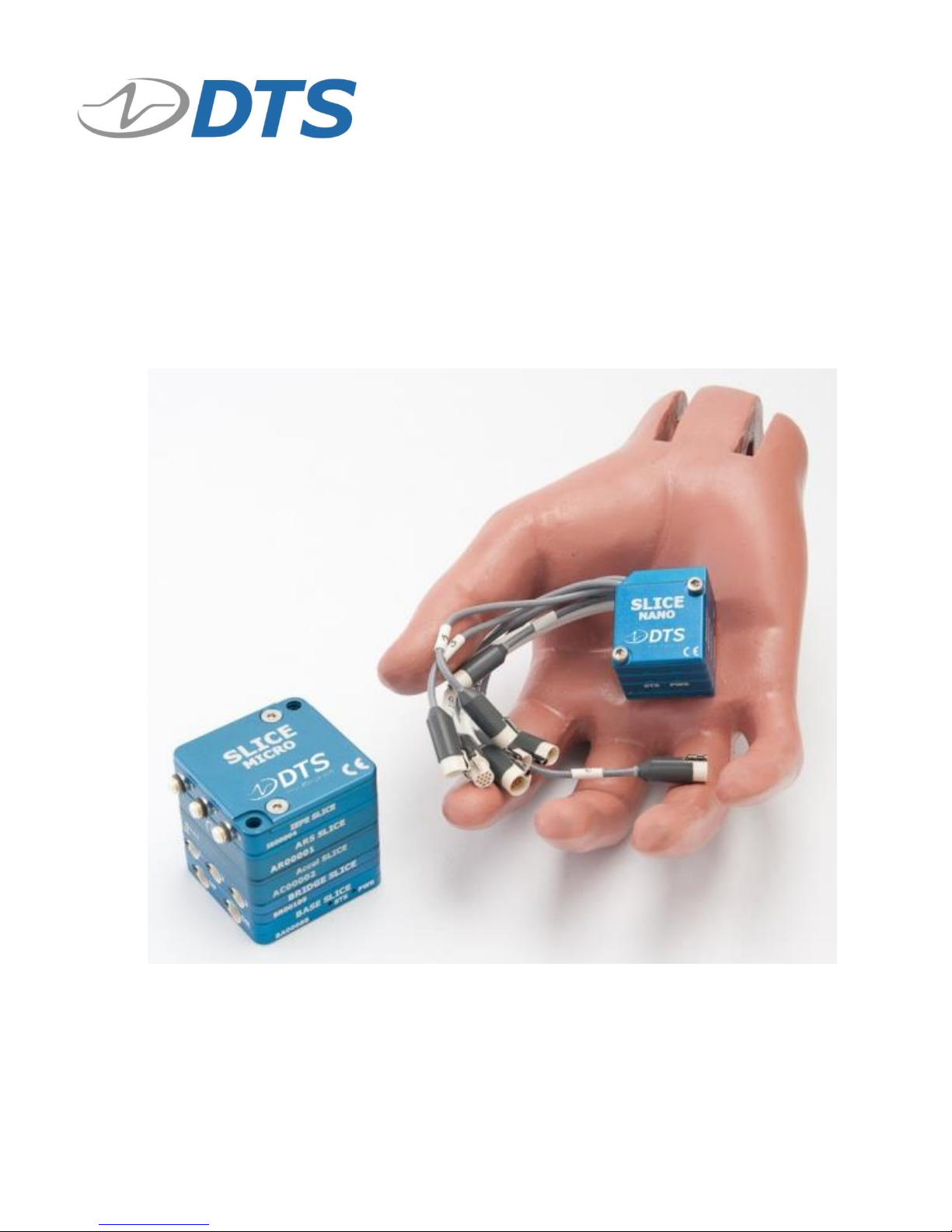
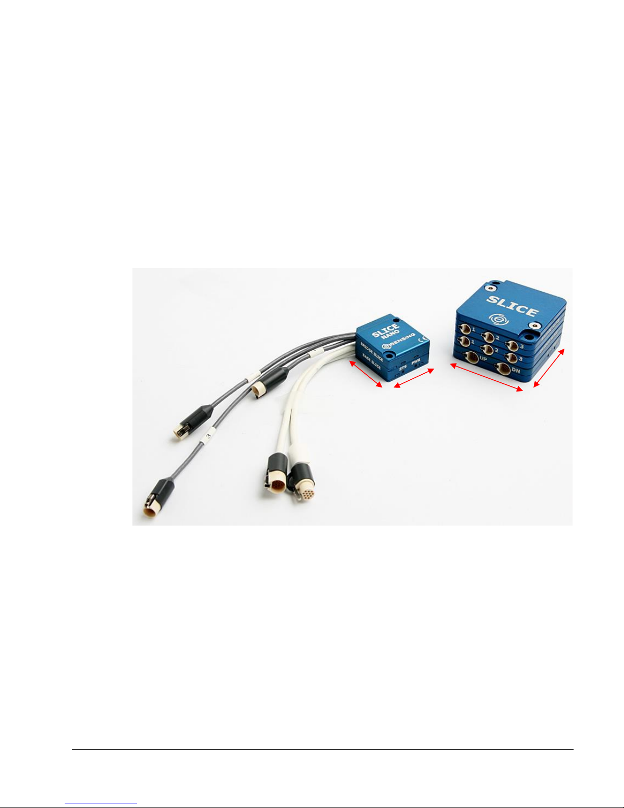
2.1. SLICE MICRO and SLICE NANO
SLICE comes in two sizes:
• SLICE MICRO (42 x 42 mm)
• SLICE NANO (26 x 31 mm)
They have the exact same function and circuit boards inside. SLICE MICRO has builtin connectors; SLICE NANO has wires with connectors.
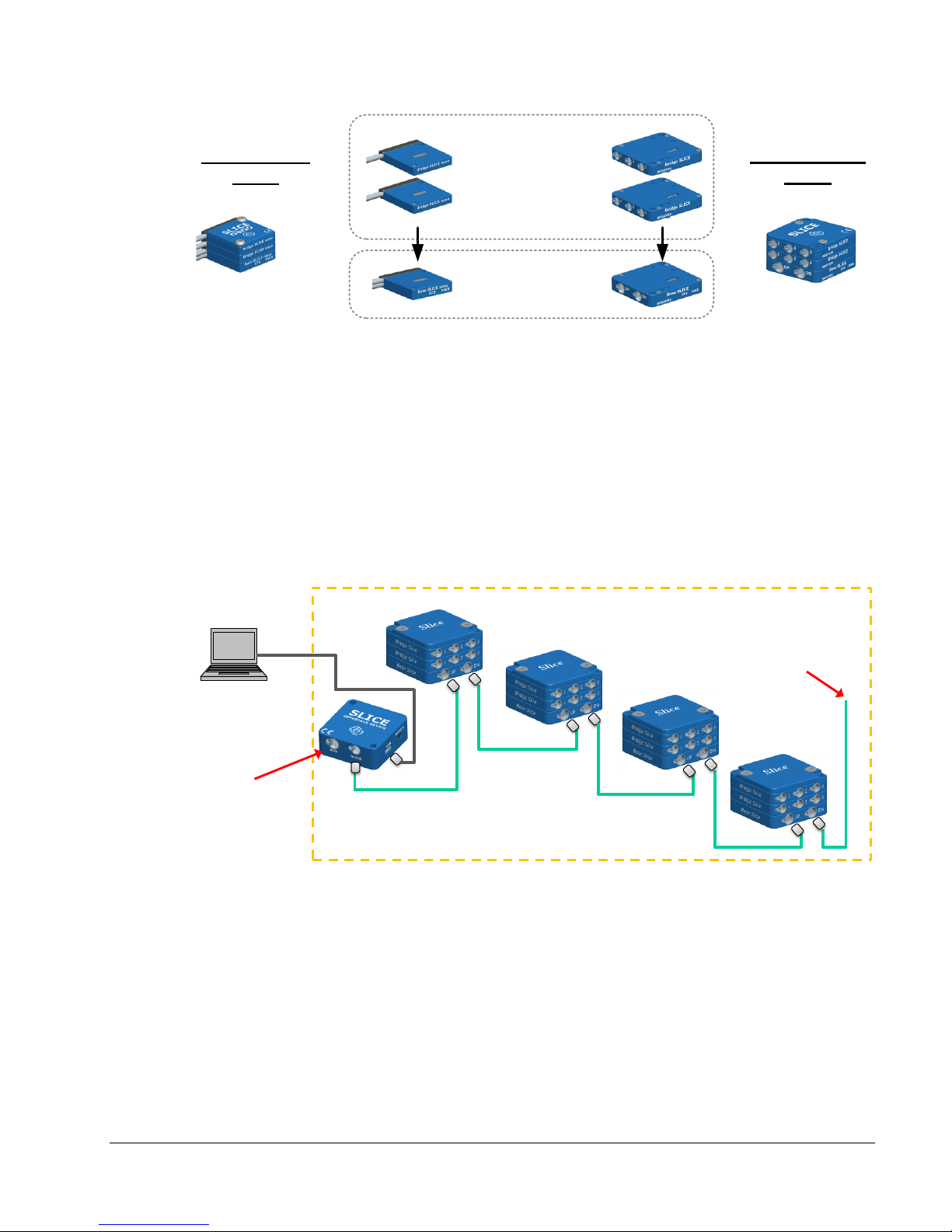
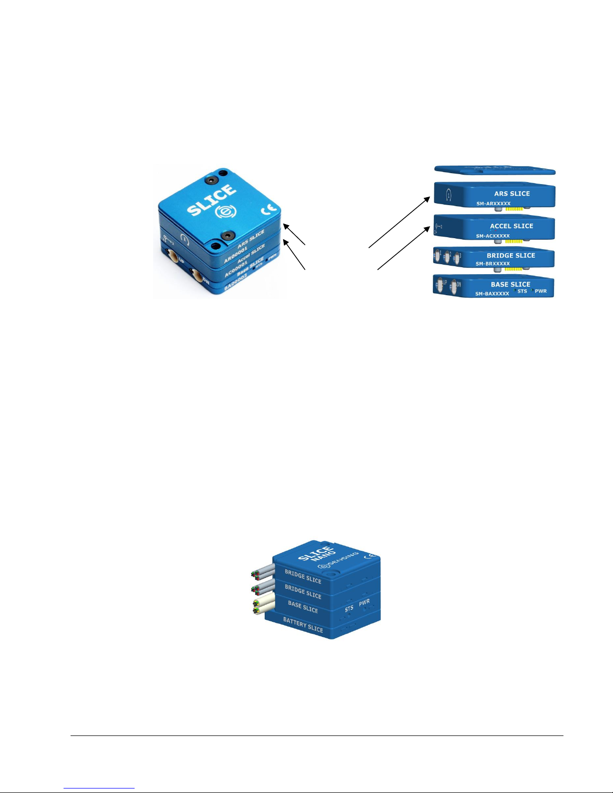
2.2. SLICE Modular Concept
Modular system – Plug multiple SLICEs onto Base+ SLICE to make a Stack
• Each SLICE “Stack” can accommodate 8 sensor input SLICES. Each Bridge
SLICE has 3 analog input channels. You may want multiple “Stacks” if more
channels are needed or placement in different locations makes sense for your
application.
• Each SLICE “Stack” consists of 1 Base+ SLICE and up to 8 additional sensor
input SLICEs.
26 mm
31 mm
42 mm
42 mm
SLICE NANO
SLICE MICRO
Page 6
SLICE User’s Manual July 2017
support.dtsweb.com 6 Version 1.0i
Example SLICE set-up with multiple Stacks:
• SLICE Stacks are mounted to the device under test and chained together.
• The End-of-Chain Terminal can be connected to a trigger, battery, or other
devices.
• The beginning of the chain is connected to the SLICE Interface Device, SLICE
Ethernet Interface, SLICE USB Interface or directly to the PC. PC can be
disconnected after arming for standalone operation.
• Up to 4 SLICE Stacks can be in any one chain.
• SLICE Distributor (not shown) allows for up to 4 SLICE chains for hundreds of
channel in one set-up.
SLICE BRIDGE
modules
Up to (8) per “Stack”
SLICE BASE module
(1) per “Stack”
SLICE NANO
Stack
SLICE MICRO
Stack
SLICE
Interface
Device
PC provides
USB control
Many options:
• Battery
• Trigger input
• Monitor status
• Up to 4 Stacks
Device Under Test
Example: Crash dummy, aircraft wing, vehicle chassis,
industrial machinery, bridge structure, etc.
Page 7
SLICE User’s Manual July 2017
support.dtsweb.com 7 Version 1.0i
2.3. SLICE Basic Hardware Components
Below are the basic components of a SLICE system. You will have some subset of
these depending on your application or what was ordered.
The table below provides an overview of the types of SLICE modules available. Some
modules are only available in the MICRO or NANO version.
SLICE Module
Description
MICRO
NANO
Base+ SLICE
One needed for each SLICE Stack
Yes
Yes
Bridge SLICE
3 channels of piezo-resistive and voltage
sensor inputs.
Yes
Yes
IEPE SLICE
3 channels of piezo-electric sensor inputs
Yes
Yes
Accel SLICE
Bridge SLICE with integrated 3-axis
accelerometer
Yes
No
ARS SLICE
Bridge SLICE with integrated 3-axis Angular
Rate Sensor
Yes
No
Stack Battery
2-cell LiPo battery connected to bottom of
Base+ SLICE
No
Yes
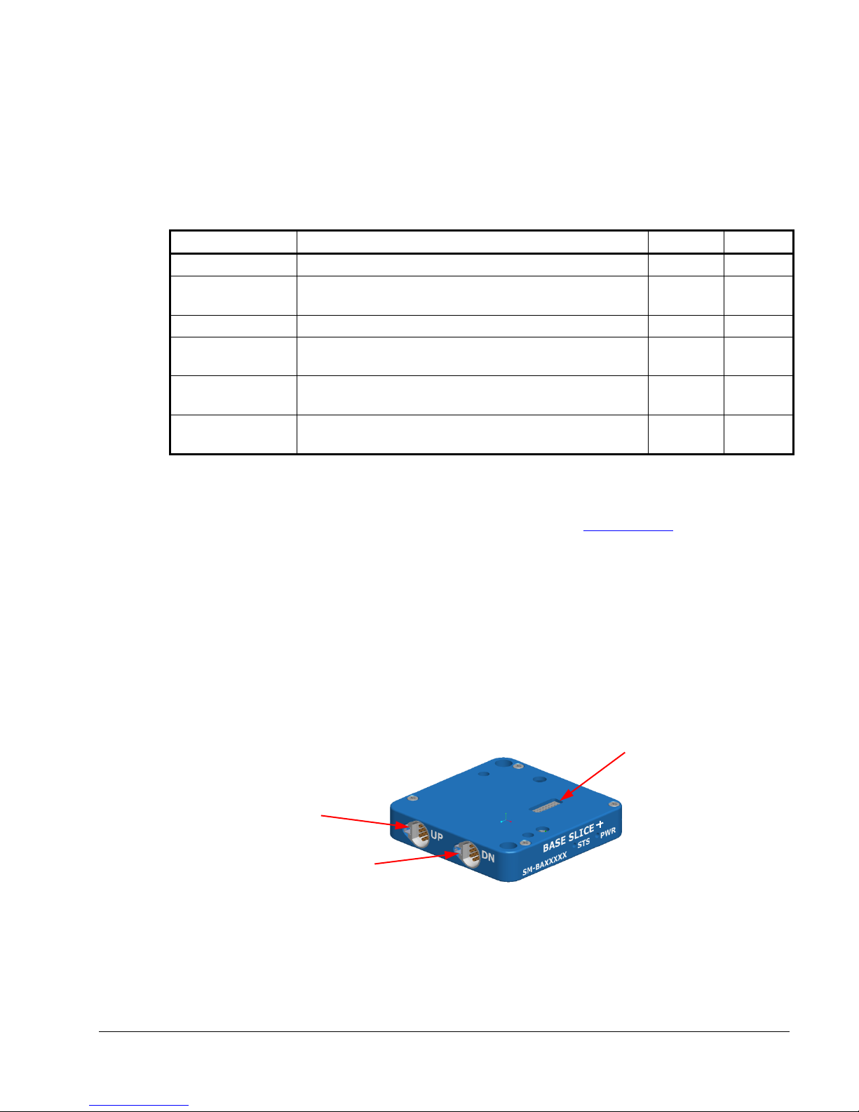
2.3.1. Base+ SLICE
See Appendix A for detailed specifications. See the DTS Support site for
information on how to update firmware.
You must have at least one Base+ SLICE for any SLICE system. The Base+
SLICE is at the bottom of the SLICE Stack and has these components:
• Microprocessor
• 16 GB flash data memory standard (15 GB available for data storage)
• USB hub
• Power conditioning
• Control signals
A Base+ SLICE MICRO is shown below.
Note: For original Base SLICE specifications, see Version 1.0g of this manual.
SLICE Bus
Up to PC
SLICE Bus
Down to next
Base+ SLICE
Connector to
Bridge SLICE or
other SLICE
input module
Page 8

SLICE User’s Manual July 2017
support.dtsweb.com 8 Version 1.0i
# of
Channels*
Maximum Sampling Rate
(per channel)
3
500,000 samples per second (sps)
6
400,000 sps
9
300,000 sps
12
200,000 sps
15
200,000 sps
18
200,000 sps
21
200,000 sps
24
200,000 sps
* All channels are recorded even if they are not programmed.
How to Calculate Maximum Storage Times
With 15 GB available for data storage, there are a total of 7.5 G samples
available in each Base+ SLICE (1 sample = 2 bytes).
To determine the maximum recording time, divide the number of samples by the
product of the sampling rate and the number of available channels in the Stack.
7,500,000,000
= # of seconds
Sampling rate (sps) X # of channels in Stack
Example 1: 10,000 sps using a 9-channel SLICE Stack
7,500,000,000
= 83,333 sec (23 hours)
10,000 X 9
Example 2: 100,000 sps using a 6-channel SLICE Stack
7,500,000,000
= 12,500 sec (3.47 hours)
100,000 X 6
Since the recording capacity of a SLICE system is very large, try to limit
sampling rates and durations to the minimum necessary to avoid large and
cumbersome data files. Large files take longer to download and may also be
time-consuming to post-process or difficult to share with colleagues. Use of the
Region of Interest (ROI) download can save a great deal of time if implemented
properly.
Page 9
SLICE User’s Manual July 2017
support.dtsweb.com 9 Version 1.0i
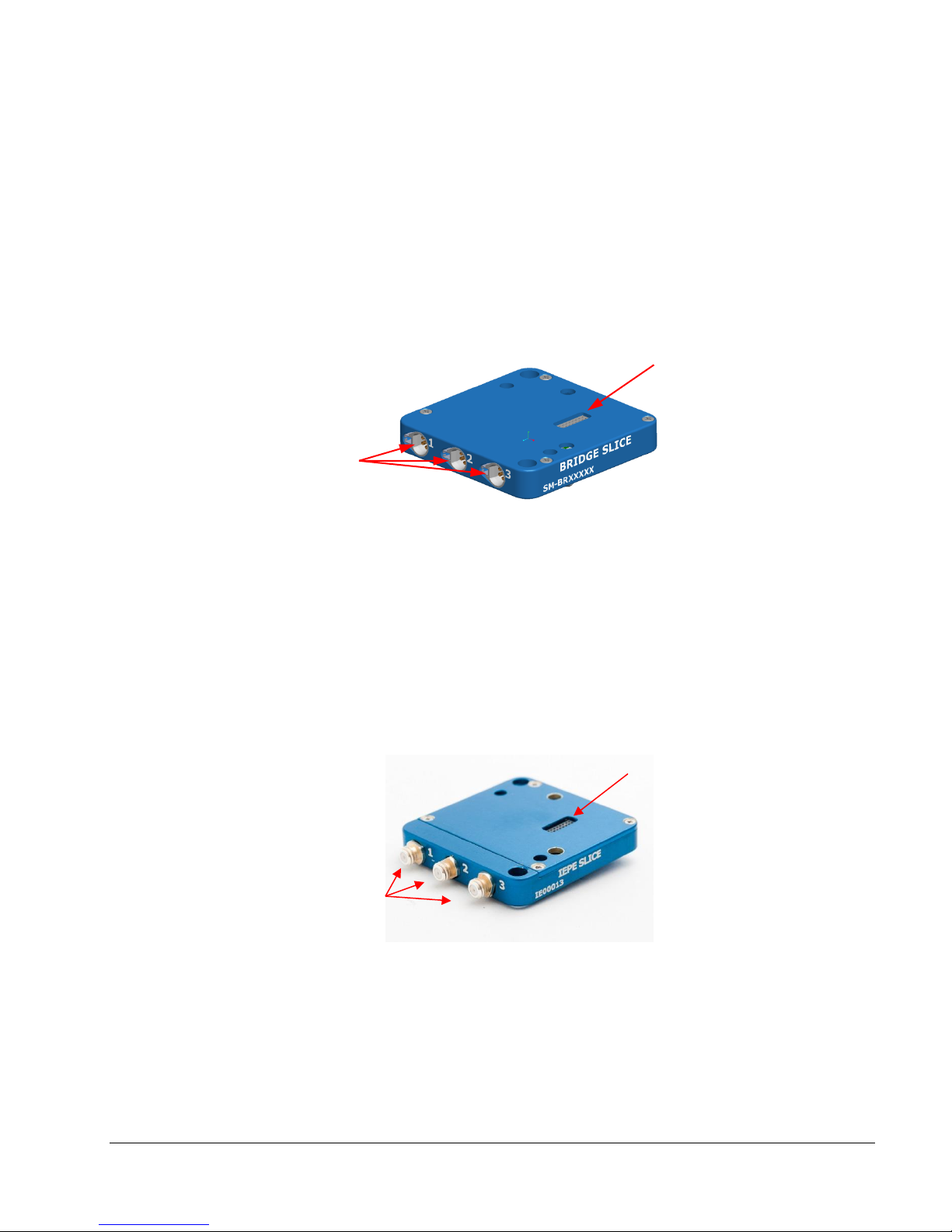
2.3.2. Bridge SLICE
See Appendix A for detailed specifications.
Up to 8 Bridge SLICEs can be stacked on top of the Base+ SLICE. Each Bridge
SLICE has these components:
• 3 channels of analog input
• Sensor excitation
• Software adjustable gain, anti-alias filters, offset, and shunt check
• TEDS sensor ID
A Bridge SLICE MICRO is shown below.
2.3.3. IEPE SLICE
See Appendix A for detailed specifications.
Features:
• 3 input channels
• One 2.2 mA constant-current source per channel at up to 24 V
• Software adjustable gain, anti-alias filters and offset
• TEDS sensor ID
An IEPE SLICE MICRO is shown below.
Sensor input
channels
Connector to
next SLICE
input module
Connector to
next SLICE
input module
Sensor input
channels
Page 10
SLICE User’s Manual July 2017
support.dtsweb.com 10 Version 1.0i
2.3.4. ACCEL SLICE
The ACCEL SLICE has Bridge SLICE electronics with the addition of a built-in 3axis accelerometer. The following specifications apply:
• Options from 25 to 500 g
• DC response
2.3.5. ARS PRO SLICE
The ARS SLICE has Bridge SLICE electronics with the addition of a built-in 3-axis
angular rate sensor. The following specifications apply:
• Uses DTS ARS PRO (see http://dtsweb.com/products/dtsars.php)
• Options from 300 to 8000 deg/sec
• DC response
2.3.6. Battery SLICE
The Battery SLICE is connected to the bottom of the Base+ SLICE. It is only
available in the SLICE NANO version. The Battery SLICE is only a back-up
battery in case main power is lost. Specifications:
• 2-cell LiPo design, with charging directly from Base+ SLICE
• Only 3.5 mm thick
Accel and ARS
SLICEs can be
positioned in any
order in a SLICE
MICRO Stack
ARS SLICE
ACCEL SLICE
Page 11
SLICE User’s Manual July 2017
support.dtsweb.com 11 Version 1.0i
2.3.7. Stack Extender
The Stack Extender is only available for the SLICE NANO package. The Stack
Extender allows the user to create a flatter, longer package.
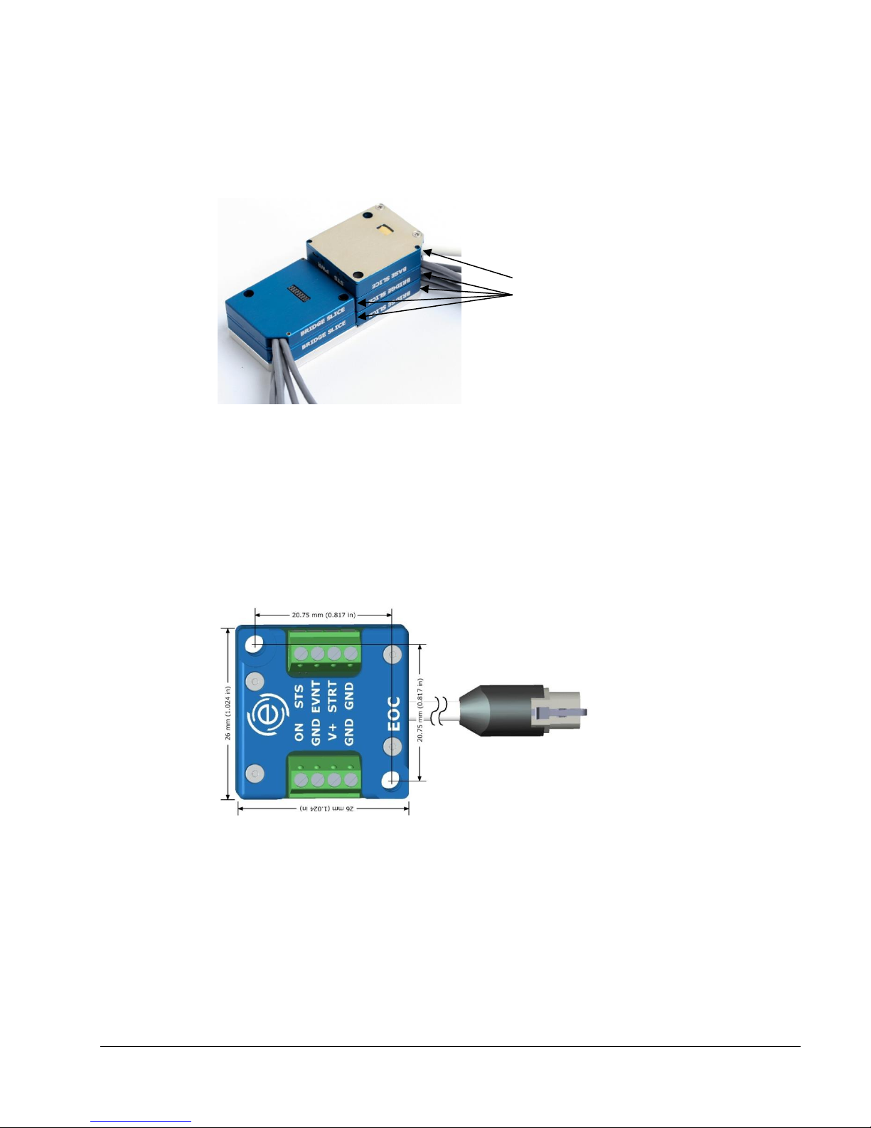
2.3.8. End-of-Chain (EOC) Terminal
See Appendix B for detailed specifications.
The EOC Terminal provides the easiest method to attach a battery, trigger signal
and status lamp to the SLICE system. It is ruggedized for high shock use.
Maximum channels:
1 chain x 2 Stacks x 8 Bridge SLICEs x 3 chan/Bridge = 48 channels
Connections:
• 2 SLICE Stack chain
• 9 to 15 VDC input power
• ON signal
• Status output, start record input and event input signals
Stack Extender
• Example: 12 channel system
• 1 Base+ SLICE
• 4 Bridge SLICEs
To DN port on Base+
SLICE MICRO or NANO
Page 12
SLICE User’s Manual July 2017
support.dtsweb.com 12 Version 1.0i
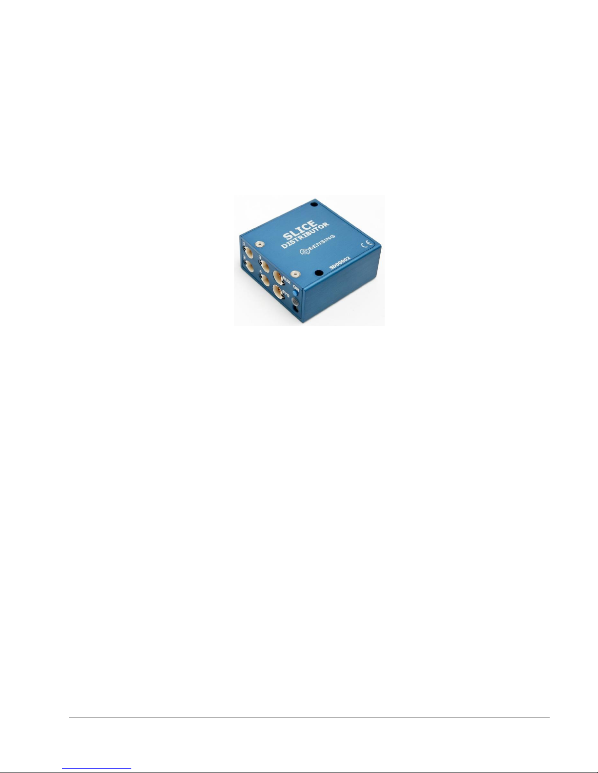
2.3.9. SLICE Distributor
See the SLICE Distributor User’s Manual for detailed information.
The SLICE Distributor serves as a single interface supporting power, Ethernet
communications and status signals for an extended SLICE system. It supports
in excess of 200 channels via four SLICE MICRO/NANO chains (four stacks per
chain), and is designed to integrate in-dummy and withstand high shock
environments. It supports 9-18 VDC input power and back-up battery input.
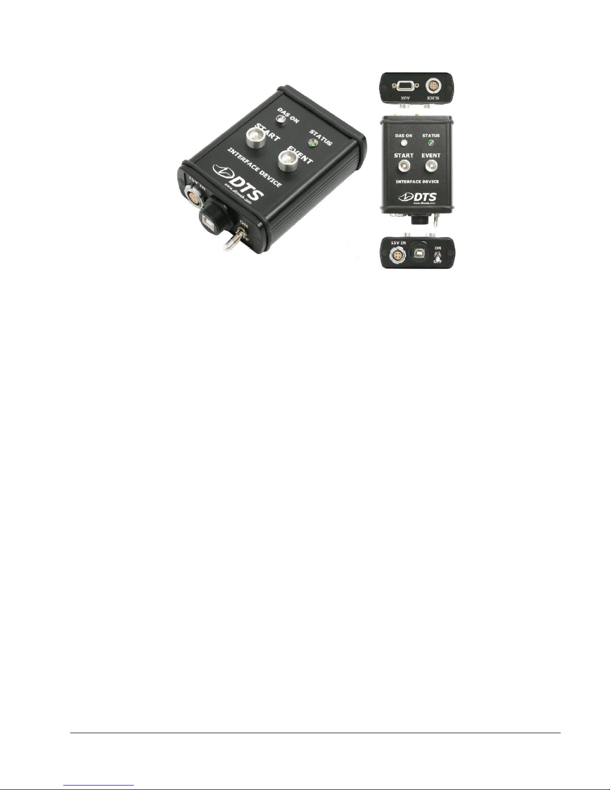
2.3.10. SLICE USB Interface
See Appendix C for detailed specifications.
The SLICE USB Interface allows the connection of one SLICE chain. It is meant
for bench-top use and is not ruggedized.
Maximum channels:
1 chain x 4 Stacks x 8 Bridge SLICEs x 3 chan/Bridge = 96 channels
Connections:
• 1 SLICE Stack chain
• USB communications
• 9 to 15 VDC input power
• ON/OFF switch
• Manual Start/Event
• AUX input (battery, trigger, etc.)
Page 13
SLICE User’s Manual July 2017
support.dtsweb.com 13 Version 1.0i
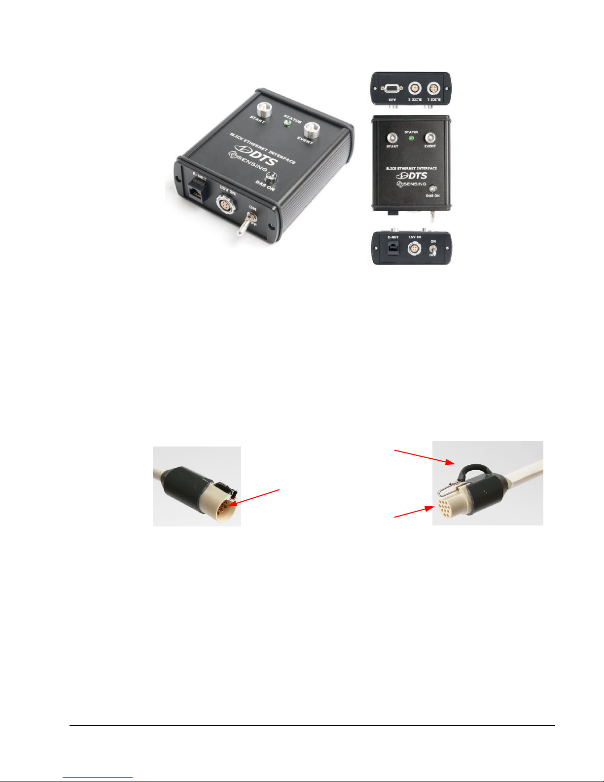
2.3.11. SLICE Ethernet Interface
See Appendix D for detailed specifications.
The SLICE Ethernet Interface allows the connection of two SLICE chains. It is
meant for bench-top use and is not ruggedized.
Maximum channels:
2 chains x 3 Stacks x 8 Bridge SLICEs x 3 chan/Bridge = 144 channels
Connections:
• 2 SLICE Stack chains
• Ethernet communications
• 9 to 15 VDC input power
• ON/OFF switch
• Manual Start/Event
• AUX input (battery, trigger, etc.)
Page 14
SLICE User’s Manual July 2017
support.dtsweb.com 14 Version 1.0i
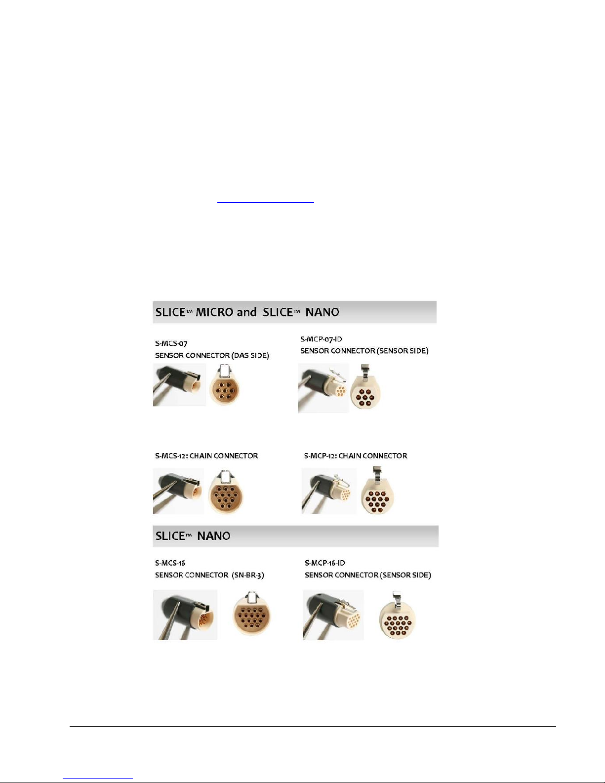
2.3.12. SLICE MICRO and NANO Connectors
See Section 3 for more connector information.
SLICE systems use lightweight, rugged plastic connectors with reliable, gold
plated contacts. These are a MIL-STD-type pin and socket configuration where
the socket is exposed, instead of the pin, which is mechanically more robust.
For some bench-top units, LEMO-style as well as industry standard USB,
Ethernet and SubD connectors are used.
A typical SLICE rugged plastic connector is shown below.
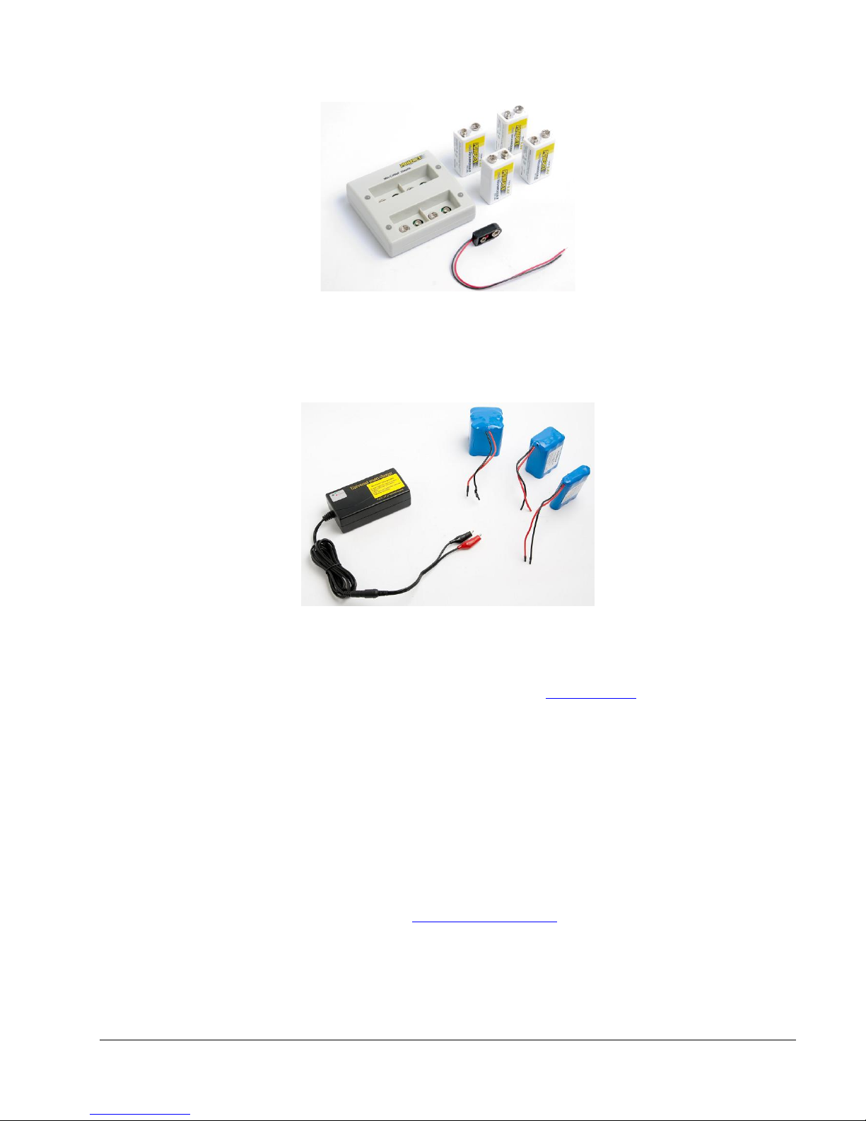
2.4. Batteries
DTS offers some commercial-off-the-shelf batteries for operation of SLICE systems.
Batteries must be disconnected from the SLICE system before connecting to a charger.
2.4.1. 9.6 V Rechargeable NiMH Batteries
• Allows up to 40 min runtime with a 6 channel SLICE System.
• Package of 4 batteries ensures you’ll always have back-ups ready to use.
Finger actuated
retention latch
Recessed pins
Exposed sockets
Page 15
SLICE User’s Manual July 2017
support.dtsweb.com 15 Version 1.0i
2.4.2. 11.1 V Rechargeable Lithium-Polymer Batteries
• Available in 3 capacities: 2200, 4400, and 6600 mAh
2.5. SLICE Software
See the SLICEWare User’s Manual for detailed information. Appendices G and H
provide information regarding file formats. See the DTS Support site for information
on how to update firmware.
The SLICEWare software application allows for easy:
• Test set-up
• Sensor database management
• Real-time sensor check-out
• Test execution
• Data download and viewing
• Data export
A SLICE API (Application Programmers Interface) driver is also available.
Please contact technical support (support.dtsweb.com) for the latest update to your
software version.
Page 16

SLICE User’s Manual July 2017
support.dtsweb.com 16 Version 1.0i
3. Mounting and Connecting SLICE Hardware
This section gives details on how to connect your SLICE hardware. Choose the connection
method you have from the options below for the quickest information.
3.1. General Connection Guidelines
Great care should always be taken when connecting any power, switch, sensor or any
other device to the SLICE system.
• DO NOT exceed the rated voltage input range for the device. Whenever
possible use the power supply or battery pack supplied with your SLICE system.
• DO NOT connect directly to vehicle power or other noisy power sources.
• ALWAYS disconnect the battery from the SLICE system before connecting to a
battery charger.
• ALWAYS use SLICE NANO with a heat sink as the SLICE NANO case is very thin
aluminum with very little heat sinking ability. Never use SLICE NANO mounted
to a thermally non-conductive surface like wood or plastic.
• Refer to proper grounding procedures described in Appendix E.
• Check that all cables show no signs of physical damage.
• Be sure all sensors have their cable shields ungrounded at the sensor end and
grounded at the SLICE input connector. (SLICE DAS units have grounded
enclosures. Sensors should be floating.)
3.2. Guidelines for High Shock and Vibration Testing
SLICE MICRO and SLICE NANO components can generally be used in test environments with maximum acceleration levels as high as 500 g. If you have purchased a
specialized high g SLICE NANO system, it can be used in environments up to 5,000 g if
proper care is taken. Please contact DTS if you have any questions about using SLICE
in high g environments.
Proper mounting of the SLICE system, cables, and accessories is critical to successful
testing.
• DO NOT mount SLICE components in an area where they may be directly
impacted by an object.
• Use damping material whenever possible to help protect the SLICE system
from excessive shock or vibration, but remember that SLICE NANO requires a
heat sink.
• Be sure that connectors and wiring are properly secured.
Page 17
SLICE User’s Manual July 2017
support.dtsweb.com 17 Version 1.0i
3.3. SLICE Connectors and Cables
3.3.1. SLICE Connectors
SLICE is an ultra small data acquisition system. One challenge with a small
system is electrical connections. Although connectors such as Bendix,
Amphenol, and LEMO are common for instrumentation, all of these are much too
large to be practical for SLICE.
The SLICE system uses circular plastic connectors manufactured by Omnetics
Corporation (www.omnetics.com). These connectors use high-quality, machined
contacts and are used in many military, aerospace and other high shock applications. Connectors are available direct from Omnetics or can be purchased from
DTS.
Below are the connector types used by SLICE. See Appendix A for complete
DTS part number information.
Page 18
SLICE User’s Manual July 2017
support.dtsweb.com 18 Version 1.0i
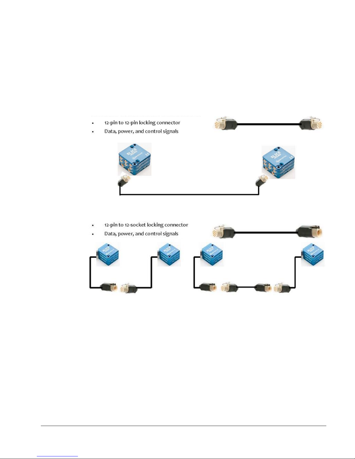
3.3.2. SLICE Cables
DTS provides a number of different SLICE cable options depending on the
connection needs. SLICE Stack-to-Stack connection cables are shown below.
SLICE MICRO Base units can be connected together via a daisy-chain cable.
SLICE NANO Base units can be connected to each other directly or via a daisychain extension cable.
13000-3005x: SLICE MICRO Chain Cable
13000-3006x: SLICE NANO Chain Cable
Connections less than 8 inches Connections from ≥8 inches to ≤2 m
A longer, more robust version of the SLICE NANO Chain Cable is available for
connections from >2 m to ≤5 m (DTS P/N 13000-3007x). (Note: the rated
maximum separation between Stacks is 5 m.)
Page 19

SLICE User’s Manual July 2017
support.dtsweb.com 19 Version 1.0i
3.4. Power Requirements
The SLICE system runs on DC power. Acceptable input power can range from 9 V
minimum to 15 or 18 V maximum, depending on the accessories used with your
system. Do not exceed the maximum input power for the accessory you are using.
To calculate the rough power needs for a particular system, use the information
below:
POWER RE QUIREMENTS
10 V POWER INPUT /5 V SENSOR EXCITATION IDLE RECO RDING
BASE SLICE 40 mA 110 mA
BRIDGE SLICE 2 mA 55 mA
SENSOR LOAD (350 ohm/5 V SENS OR EXCITATION ) 0 mA 50 mA
SINGLE STACK POWER C ONSUMPTION AT 5 V SENS OR
EXCITATION
TOTAL
BASE (QTY) 1
BRIDGE (QTY) 2
SENSOR LOAD (% of 350 ohm) 100
IDLE C URRENT 44 mA
IDLE P OWER 330 mW
RECORD CURRENT 320 mA
RECORD POWER 2400 mW
Page 20
SLICE User’s Manual July 2017
support.dtsweb.com 20 Version 1.0i
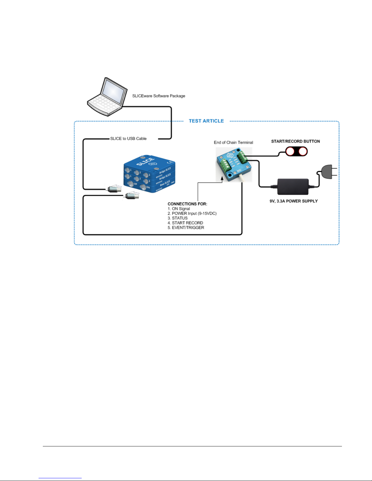
3.5. Using the End-of-Chain (EOC) Terminal
A diagram showing connections using the EOC Terminal is shown below.
Notes:
• Although this shows a SLICE MICRO system, connections with a SLICE NANO
are similar.
• The EOC Terminal is a shock rated item.
• Voltage input can be provided via the included power supply, a battery or any
voltage source between 9 and 15 VDC. Warning: Do not exceed the 15 VDC
input voltage range as damage may result.
• The ON terminal must be connected to the GND on the EOC Terminal for the
SLICE unit to turn on.
• If you connect an LED between the STS and GND terminals, you will get a
Status light when the system is armed.
Page 21

SLICE User’s Manual July 2017
support.dtsweb.com 21 Version 1.0i
See Appendix B for detailed information on the SLICE End-of-Chain Terminal.
3.6. Using the SLICE USB Interface
The SLICE USB Interface is designed for bench-top, non-rugged use. See the example
diagram below.
To DN port on the last
Base+ SLICE MICRO
or NANO in a SLICE
Page 22

SLICE User’s Manual July 2017
support.dtsweb.com 22 Version 1.0i
Notes:
• Although this shows a SLICE MICRO, connections with a SLICE NANO are
similar.
• The SLICE USB Interface is NOT a shock rated item.
• Voltage input can be with the included power supply a battery, or any voltage
source between 9 and 15 VDC. Warning: Do not exceed the 15 VDC input
voltage range as damage may result.
• The AUX connector is a standard D-sub HD15. This can be used to hardwire a
Start Record or Event switch or monitor the Status line.
3.7. Using the SLICE Ethernet Interface
The SLICE Ethernet Interface is similar to the SLICE USB Interface. The main
difference is that the SLICE Ethernet Interface has an Ethernet connection to the PC
instead of a USB connection. This allows for a longer communications cable between
the PC and the SLICE system. The SLICE Ethernet Interface can also connect 2 SLICE
chains for large system configurations. See the example diagram below.
Notes:
• Although this shows a SLICE MICRO, connections with a SLICE NANO are
similar.
• The SLICE Ethernet Interface is NOT a shock rated item.
• Voltage input can be with the included power supply a battery, or any voltage
source between 9 and 15 VDC. Warning: Do not exceed the 15 VDC input
voltage range as damage may result.
Page 23

SLICE User’s Manual July 2017
support.dtsweb.com 23 Version 1.0i
• The AUX connector is a standard D-sub HD15. This can be used to hardwire a
Start Record or Event switch or monitor the Status line.
3.8. Using the SLICE Distributor
The SLICE Distributor allows for the connection of up to 4 SLICE chains and converts
the communications signals from USB to Ethernet. This allows for a longer communications cable between the PC and the SLICE system. The most common application
for the SLICE Distributor is for an embedded system with a high channel count as
shown for the in-dummy (manikin) configuration below.
SLICE Application Diagram: 42-channel integrated
SLICE NANO for H3-50% Dummy
Page 24

SLICE User’s Manual July 2017
support.dtsweb.com 24 Version 1.0i
4. Sensor ID and Supported Sensor Types
This section covers basic information regarding SLICE compatible sensors and sensor ID.
More detailed information regarding sensor connections can be found in Appendix F.
The diagram below shows a common 4-wire bridge sensor connection to a Bridge SLICE
input channel.
4.1. Sensor ID
Sensor ID is also referred to as electronic ID (EID). The function of EID is for the
SLICE hardware to automatically read and determine what sensor is attached to each
sensor input channel.
SLICE uses EID chips from Maxim IC, model DS2401 (see http://www.maxim-
ic.com/quick_view2.cfm/qv_pk/2903). To make soldering of the EID easier, DTS
provides EID microcards, which have a chip scale packaged DS2401 soldered to a
circuit board with wires attached (see below).
Page 25

SLICE User’s Manual July 2017
support.dtsweb.com 25 Version 1.0i
4.2. Supported Sensor Types
The Bridge SLICE supplies 5 VDC excitation up to 20 mA and supports many types of
accelerometers, load cells, pressure sensors and other sensor types. The following
general sensor types are supported:
• Full (4-wire) or half bridge (2- or 3-wire) resistive and piezo-resistive types
• Voltage input: Input range 0.1 to 4.9 V; larger range with voltage expander
circuit
• Conditioned sensors with 5 V excitation and 2.5 V centered signal output
• Common piezo-electric sensor types
If you have questions regarding what sensors are supported, please contact
support.dtsweb.com and provide the sensor manufacturer and model number if
available.
EID “microcard” soldered to pins 4 and 6
Omnetics 7-pin Sensor Connector
Page 26

SLICE User’s Manual July 2017
support.dtsweb.com 26 Version 1.0i
5. Software
See the SLICEWare User’s Manual for detailed information. Appendices G and H provide
information regarding file formats. See the DTS Support site for information on how to
update firmware.
5.1. Basic Requirements
SLICEWare is a Windows® based program. Minimum PC specifications are:
• Windows Vista, or Windows 7. 32- and 64-bit versions are available.
• 1 GHz or faster processor
• 2 GB RAM minimum. More RAM is important for longer/higher sample rate data
acquisition.
• 100 MB disk space for Software plus storage for test data
• 1024 x 768 minimum screen resolution
5.2. Data Collection Concepts
This section discusses the basics of data collection with SLICE.
5.2.1. Standalone Operation
SLICE is a standalone data logger. This means that once it is armed, the PC can
be disconnected if desired. After receiving a Start Record or Trigger signal, the
SLICE autonomously collects data, storing it to flash memory with no user
interaction. After the test, the user can reconnect the PC to download the data.
There is also a real-time mode in the SLICEWare software application that
allows the user to check channel inputs on an oscillograph-looking screen. (This
data can be logged.)
5.2.2. Data Collection Modes
SLICE supports four data collection modes: Circular Buffer, Recorder, Hybrid
Recorder, and Continuous Recorder. (Note: SLICEWare cannot simultaneously
display the data while the system is recording.)
5.2.2.1. Circular Buffer Mode
In circular buffer mode, the user can program SLICE to record pre-trigger
data. For example, the test set-up can specify to record x seconds pretrigger and x seconds post trigger. Time Zero (T=0) is marked when the
trigger signal is received.
5.2.2.2. Recorder Mode
Recorder mode starts when a Start Record signal is received and continues
for the time specified in the test set-up. If a trigger signal is received
sometime after the Start Record, this marks the T=0 point.
5.2.2.3. Hybrid Recorder Mode
Page 27

SLICE User’s Manual July 2017
support.dtsweb.com 27 Version 1.0i
Hybrid Recorder mode starts when a Start Record signal is received and
continues until the unit receives a trigger signal and then records for the
post-trigger time specified by the host software. The trigger signal marks
the T=0 point and all data recorded is available for download.
5.2.2.4. Continuous Recorder Mode
Continuous Recorder mode starts when a Start Record signal is received
and continues until the Start Record signal is released. The unit will then
re-arm for another event. The LEDs on the unit will flash blue slowly then
rapidly, and then the STATUS LED will become solid blue, indicating the
unit is fully armed. The unit will continue to record new events until it
records the number of events specified by the host software. If a trigger
signal is received after the unit has re-armed the unit will disarm and no
longer attempt to re-arm.
5.2.3. Multiple-Event Modes
All SLICE data collection modes have an equivalent multi-event arming mode. A
unit armed in a multiple-event mode will re-arm when an event completes. The
unit will stop re-arming when the number of events specified by the host
software has been recorded.
5.2.4. Auto-Arm Data Collection
SLICE can be placed in an auto-arm mode that will cause the unit to arm
automatically when the power cycled. The unit can be placed into this mode
and record with any data collection mode.
NOTE:
An event or trigger signal applied anywhere in the SLICE chain is
distributed throughout the system. This applies to level trigger as
well.
Page 28

SLICE User’s Manual July 2017
support.dtsweb.com 28 Version 1.0i
6. Powering Up SLICE
This section covers what to expect when powering up a SLICE system and running a test.
The LEDs on the Base+ SLICE indicate the status of the system.
To initialize SLICE MICRO/NANO systems without power back-up:
1. Apply power to the Base.
2. Connect the SLICE system to the PC via the comm cable.
3. Initialize the software to enable communication.
If your system includes a battery (SLICE NANO Stack Battery or SLICE HG system), it is
important that the internal capacitors be allowed to charge briefly before system initialization.
An ON hardware signal is used to initialize the SLICE system; be sure to disable the ON
signal prior to applying power.
To initialize SLICE NANO/HG systems that include power back-up:
1. Remove the hardware ON signal from your system.
2. Apply power to the Base.
3. Wait ~15 seconds to allow the internal capacitors to charge briefly.
4. Enable the hardware ON signal and connect the SLICE system to the PC via the comm
cable. (The LEDs will complete the power up sequence as soon as the ON signal is
applied.)
5. Initialize the software to enable communication.
6.1. Status (STS) LED
Action
Result
Power up
Communicating with PC
Recording Data (Recorder Mode) -or- Armed (Circular Buffer)
Armed in Recorder Mode
Unit received Event
Idle
+
Page 29

SLICE User’s Manual July 2017
support.dtsweb.com 29 Version 1.0i
The status LED is red, green or blue. At system power up, the LED cycles from red to
green to blue followed immediately by the power LED boot-up sequence.
The status LED indicates communication and arm status.
• When the unit is not armed, the status LED will blink green when handling a
command from the PC.
• For Recorder Mode
o When the unit is first armed, the LED will go solid blue to indicate that it
is waiting for the START RECORD signal but not taking data.
o When it receives the START RECORD signal, the LED will turn green to
indicate that it is actively recording data.
o The LED will turn off when data collection has completed.
o If an EVENT signal is received while the unit is recording data, the LED
will turn red and then turn off when data collection has completed.
• For Circular Buffer Mode
o When the unit is armed, the LED will go solid green to indicate that it is
collecting data and waiting for the EVENT signal.
o When an EVENT signal is received the LED will turn red and then turn off
when data collection has completed.
6.2. Power (PWR) LED
Action
Result
(not armed)
Power up
Connected to USB power Only
Connected to external power – power is OK
Connected to external power – power is low
The power LED is red, green or blue.
• At power up, the LED cycles from red to green to blue immediately after the
status LED has completed its boot-up sequence.
• When USB is connected, the LED will turn blue.
• With OK external power, the LED will turn green.
• With low external power, the LED will turn red.
• These transitions do not happen if the unit is armed.
Page 30

Specifications
BASE+ SLICE (NANO & MICRO)
One (1) required per stack – system microprocessor & memory
Size: MICRO 42 x 42 x 8 mm (1.65 x 1.65 x 0.32”)
Mass: MICRO 28 g (0.99 oz), NANO 14.2 g (0.50 oz)
Connectors: Omnetics, circular locking, 12-pin
Number of
SLICEs
Per Stack*
Total
Channel
Count
1 3 ch 500000
2 6 ch 400000
3 9 ch 300000
4 12 ch 200000
5 15 ch 200000
6 18 ch 200000
7 21 ch 200000
8 24 ch 200000
Maximum
Sampling Rate
SPS/Channel
Compatibility: BASE+ works will all legacy NANO & MICRO
ENVIRONMENTAL
Military Standard: MIL-STD-810E
Operating Temp: -40° to 60°C (-40° to 140°F) (Method 501,502)
Altitude: -40°C @ 15240 m (50000 ft ) (Method 500)
Vibration (Random): Exceeds 810-E vibration (Method 514)
Humidity: 95% RH non-condensing
Shock: 500 g, 4 msec half sine
DATA RECORDING
Modes: Recorder, circular buffer, multiple event, arm on
Memory: 16 GB non-volatile flash per SLICE stack
Sample Rate: Minimum 10 sps per channel
<See Chart for Max: Up to 200k sps on ≤24 channels per stack
*Not including the one required
BASE+ SLICE per stack
TRIGGERING
Hardware Trigger: Contact closure & TTL logic-level (active low)
Level Trigger: Positive and/or negative level on any active
POWER
Supply Voltage: 9-15 VDC; >11 VDC when using Battery SLICE
SERVICES
24/7 Worldwide Tech Support
ISO 17025 (A2LA) Calibration
Onsite Calibration & Training
Current (Maximum): 70 mA @ 12 V plus sensor input SLICEs
Power Control: Remote power control input for on/off
Protection: Reverse current, ESD
SOFTWARE
Control: SLICEWare, DataPRO, API
Operating Systems: Windows® Vista/7/8 (32/64-bit)
Communication: USB; Ethernet available via SLICE Distributor
Application Consulting
Software Integration
OEM/Embedded Applications
Michigan, United States
United Kingdom
France
Japan
Asia Pacific
HEADQUARTERS
Seal Beach, California USA
Phone: +1 562 493 0158
Email: sales@dtsweb.com
BRIDGE SLICE (NANO & MICRO)
Three (3) inputs for external sensors
Size: MICRO 42 x 42 x 7 mm (1.65 x 1.65 x 0.32”)
Ma ss: MICRO 25 g (0.88 oz), NANO 13.8 g (0.49 oz)
Connectors: Omnetics, circular locking; 3 single-channel
SIGNAL CONDITIONING
Number of Channels: 3 differential, programmable
Input Range: ±2.4 V (2.5 V center)
Bandwidth: DC to 40 kHz, programmable
Gain Range: 1.0-1280, programmable
Auto Offset Range: 100% of effective input range
Bridge Support: Software controlled half-bridge completion
Shunt Check: Emulation method, automatically calculated
Sensor ID: Maxim Integrated (Dallas) silicon serial number
Linearity (typical): 0.2% (gain 1 to 320), 0.5% (gain >320)
Accuracy: 0.5% including reference uncertainty
ANALOG-TO-DIGITAL CONVERSION
Type: 16-bit SAR (Successive Approximation
EXCITATION
Method: Independent regulator for each channel
Voltage: 5.0 V, up to 20 mA, short circuit safe
Power Management: Shutdown when not armed or recording
POWER
Voltage: Supplied via BASE SLICE
Current (Maximum): 110 mA with 350 ohm bridges all channels
ANTI-ALIAS FILTER
Fixe d Lo w Pa ss: 4-pole Butterworth, standard knee frequency at 40 kHz
Adju stab le L ow P ass: 5-pole Butterworth set by software from 1 Hz to 40 kHz
Response: Meets SAE J211/ISO6487 response corridors
NANO 26 x 31 x 6.5 mm (1.02 x 1.22 x 0.26”)
MICRO integrated, NANO cable assembly
5000 g option (SLICE NANO only)
power-up, and other modes available
Up to 500k sps on ≤3 channels per stack
sensor channel (first level crossing of any
programmed sensor triggers system)
(NANO)
NANO 26 x 31 x 5.5 mm (1.02 x 1.22 x 0.22”)
7-pin or 1 three-channel 16-pin
Register) ADC, one per channel, simultaneous
sample of all channels.
Power varies significantly with sensor load
IEPE SLICE (NANO & MICRO)
Three (3) inputs for external sensors
Size: MICRO 42 x 42 x 7 mm (1.65 x 1.65 x 0.28”)
Mass: MICRO 28 g (0.99 oz), NANO 23 g (0.81 oz)
Connectors: 10-32 coaxial (Microdot-compatible)
NANO 26 x 46 x 7 mm (1.02 x 1.81 x 0.28”)
SIGNAL CONDITIONING
Number of Channels: 3
Input Range: 0.5-23.5 V (12 V center)
Bandwidth: DC to 40 kHz, programmable
Gain Options: 1 or 10, user programmable
Auto Offset Range: 100% of effective input range at gain of 1
Sensor ID: Works with EID or “TEDS” equipped sensors
ANALOG-TO-DIGITAL CONVERSION
Type: 16-bit SAR (Successive Approximation
Register) ADC, one per channel, simultaneous
sample of all channels.
EXCITATION
Current/Voltage: 2.2 mA constant current with 25 V source.
On/Off Control: Shutdown when not armed or recording
Contact DTS for other options if needed.
POWER
Voltage: Supplied via BASE SLICE
Current (Maximum): 85 mA with sensors connected to all channels
ANTI-ALIAS FILTER
Fixed Low Pass: 4-pole Butterworth, standard knee frequency
Adjustable Low Pass: 5-pole Butterworth set by software from 1 Hz to
Response: Meets SAE J211/ISO6487 response corridors
at 40 kHz
40 kHz
CALIBRATION
Calibration Supplied: NIST traceable
ISO 17025: ISO 17025 (A2LA Accredited) available
Service Options: Factory or Onsite, Service Contracts available
ARS SLICE (MICRO only)
Built-in triaxial angular rate sensor
Size: MICRO 42 x 42 x 9 mm (1.65 x 1.65 x 0.35”)
Mass: 30 g (1.06 oz)
Number of Channels: 3 orthogonal axes
Range Options: ±300, ±1500, ±8k deg/sec
Bandwidth: 0–2,000 Hz
Current (Maximum): 75 mA (power supplied via BASE SLICE)
ACCEL SLICE (MICRO only)
Built-in triaxial accelerometer
Size: MICRO 42 x 42 x 9 mm (1.65 x 1.65 x 0.35”)
Mass: 30 g (1.06 oz)
Number of Channels: 3 orthogonal axes
Range Options: ±25, ±100, ±500 g
Bandwidth: 0–400 Hz (±25, ±100 g), 0–5,000 Hz (±500 g)
Current (Maximum): 65 mA (power supplied via BASE SLICE)
BATTERY SLICE (NANO only)
Optional back-up battery
Size: NANO 26 x 31 x 4 mm (1.65 x 1.65 x 0.16”)
Mass: 7 g (0.25 oz)
Charge Status: Backup battery charges when input voltage to
Charge Time: ~15 min. from complete discharge to full charge
Discharge Rate: ~5 seconds with 18 channels (1 Base + 6 Bridges)
BASE SLICE is >11 VDC
(100 mA at input connector on Base)
ACCESSORIES
See website for full line of SLICE NANO & SLICE MICRO accessories
www.dtsweb.com
Specifications subject to change without notice.
© Diversified Technical Systems, Inc.
Page 31

SLICE NANO Base Pin Assignments
July 2011 © Diversified Technical Systems, Inc. - All Rights Reserved
DOWN connector**
(looking into the connector)
Mating connector: DTS
P/N 80000-04030
Mating connector + backshell: DTS P/N 13000-30170
Pin Function
1
On (contact closure input to ground)
2
Start (contact closure input to ground)
3
Event (contact closure input to ground)
4
Status output (5 V via 10K with respect
to ground)
5, 6
7–15 VDC
7, 8, 12
Ground
9
USB_PWR
10
USB_DP
11
USB_DM
** Both cables are 10 cm in length
UP* connector**
(looking into the connector)
Mating connector: DTS P/N 80000-04029
Mating connector + backshell: DTS P/N 13000-30180
Pin Function
1
On (contact closure input to ground)
2
Start (contact closure input to ground)
3
Event (contact closure input to ground)
4
Status output (5 V via 10K with respect
to ground)
5, 6
7–15 VDC
7, 8, 12
Ground
9
USB_PWR
10
USB_DP
11
USB_DM
* to PC
1
3
4
7
8
10
12
11
3
1
7
4
10
8
11 12
Page 32

SLICE NANO Bridge Pin Assignments
July 2017 ©Diversified Technical Systems, Inc. - All Rights Reserved
Channels 1, 2 and 3*
(looking into the connector)
Mating connector: DTS P/N 80000-04019
Mating connector + backshell:
DTS P/N 13000-30310
Mating connector + backshell + ID:
DTS P/N 13000-30120
Pin
Function
1
+ Sig
2
- Sig
3
+ Ex
4
+ ID
5**
- Ex
6**
- ID
7**
Shield
* Three connectors; cables 6, 10
and 14 cm in length
** Pins 5, 6 and 7 are common
Pin
Function
1
+ Sig (Ch 1)
2
+ ID (Ch 1)
3
- Sig (Ch 2)
4
+ Sig (Ch 2)
5
- Sig (Ch 1)
6
+ Ex (Ch 1)
7
- Ex (Ch 1)
8
+ Ex (Ch 2)
*** One connector; cable 10 cm in length
Pin
Function
9
+ ID (Ch 2)
10
+ Sig (Ch 3)
11
+ Ex (Ch 3)
12
- Ex (Ch 3)
13
- Ex (Ch 2)
14
- Sig (Ch 3)
15
+ ID (Ch 3)
16
- ID (Ch 1, 2, 3)/Shield
-Ex/-ID/Shield are common
1
2
3 5 6
7
Channels 1-3***
(looking into the connector)
Mating connector: DTS P/N 80000-14031
Mating connector + backshell: DTS P/N 13000-30320
Mating connector + backshell + 3 IDs: DTS P/N 13000-30140
1 4 5
9
10
13
14
16
Ch 1
Ch 3
Ch 2
Page 33

SLICE NANO Mechanical Specifications
July 2017 ©Diversified Technical Systems, Inc. - All Rights Reserved
Ø3.2 mm (0.125 in) mounting thru holes x2
Accepts M2.5 (loose fit); 4-40 (free fit); M3 (tight fit)
Weight (+5 g)
Height
Lid
2.6 g
1.5 mm (0.059 in)
IEPE*
23 g
7 mm (0.276 in)
Bridge (1 conn)**
12.6 g
5.5 mm (0.217 in)
Bridge (3 conn)**
13.8 g
5.5 mm (0.217 in)
Base**
14.2 g
6.5 mm (0.256 in)
Battery
7 g (+1 g)
4 mm (0.157 in)
Extended Capacity Battery
20 g
16 mm (0.630 in)
** Includes cable assemblies
See the DTS Support site for future updates.
Total Stack Height
mm (inch)
Mounting Screw Length (min)
BH or SHC
M2.5*/M3**
4-40**
13.5 (0.531)
18 mm
3/4"
17.5 (0.689)
22 mm
7/8"
19 (0.748)
25 mm
1"
23 (0.906)
30 mm
1-1/8"
24.5 (0.965)
30 mm
1-1/8"
28.5 (1.122)
35 mm
1-1/4"
30 (1.181)
35 mm
1-3/8"
34 (1.339)
40 mm
1-1/2"
35.5 (1.398)
40 mm
1-3/4"
39.5 (1.555)
45 mm
1-3/4"
41 (1.614)
45 mm
1-3/4"
45 (1.772)
50 mm
2"
46.5 (1.831)
60 mm
2"
50.5 (1.988)
60 mm
2-1/2"
52 (2.047)
60 mm
2-1/2"
56 (2.205)
60 mm
2-1/2"
57.5 (2.264)
70 mm
2-1/2"
61.5 (2.421)
70 mm
3"
63 (2.480)
70 mm
3"
67 (2.638)
70 mm
3"
Specifications may be revised without notice. Torque specs: * 3.9 in-lb (0.44 Nm); ** 5.2 in-lb (0.59 Nm)
D C C
B B A
90° cable
clearance
Cables
A = 26 mm (1.024 in)
B = 20.75 mm (0.817 in)
C = 2.62 mm (0.103 in)
D = 31 mm (1.220 in)
D = 46 mm (1.811 in)*
Page 34

SLICE MICRO Pin Assignments
July 2011 © Diversified Technical Systems, Inc. - All Rights Reserved
DOWN and UP* conne
ctors for SLICE MICRO Base
(looking into the connector)
Mating connector: DTS P/N 80000-04030
Mating connector + backshell: DTS P/N 13000-30170
Pin Function
1
On (contact closure input to ground)
2
Start (contact closure input to ground)
3
Event (contact closure input to ground)
4
Status output (5 V via 10K with respect
to ground)
5, 6
7–15 VDC
7, 8, 12
Ground
9
USB_PWR
10
USB_DP
11
USB_DM
* to PC
Channels 1, 2 and 3 for SLICE MICRO Bridge
(looking into the connector)
Mating connector:
DTS P/N 80000-04019
Mating connector + backshell: DTS P/N 13000-30310
Mating connector + backshell + ID: DTS P/N 13000-30120
Pin Function
1 + Sig
2 - Sig
3 + Ex
4 + ID
5* - Ex
6* - ID
7* Shield
* Pins 5, 6 and 7 are common
1
3
4
7
8
10
12
11
1 2
3
5
6
7
Page 35

SLICE MICRO Mechanical Specifications
July 2011 © Diversified Technical Systems, Inc. - All Rights Reserved
Weight
Height
mm (i
nch)
Lid ~9 grams 2 (0.079)
IEPE ~28 grams 7 (0.276)
Accel ~33 grams 9 (0.354)
ARS ~33 grams 9 (0.354)
Bridge ~25 grams 7 (0.276)
Base ~28 grams 8 (0.314)
Assembly Screw
Length (F
H)
Mounting Screw Length (min)
(BH or SHC)
Total Stack Height
mm (inch)
M3* M4** 6-32***/8-32**
17 (0.67) 16 mm 22 mm 7/8"
24 (0.95) 20 mm 30 mm 1-1/4"
26 (1.02) 25 mm 35 mm 1-1/4"
31 (1.22) 30 mm 35 mm 1-1/2"
33 (1.30) 30 mm 40 mm 1-1/2"
35 (1.38) 35 mm 40 mm 1-5/8"
38 (1.50) 35 mm 45 mm 1-3/4"
40 (1.57) 40 mm 45 mm 1-3/4"
42 (1.65) 40 mm 50 mm 2"
45 (1.77) 45 mm 50 mm 2"
47 (1.85) 45 mm 55 mm 2-1/4"
49 (1.93) 45 mm 55 mm 2-1/4"
52 (2.05) 50 mm 60 mm 2-1/4"
54 (2.13) 50 mm 60 mm 2-1/2"
56 (2.21) 55 mm 70 mm 2-1/2"
59 (2.32) 55 mm 70 mm 2-1/2"
61 (2.40) 60 mm 70 mm 3"
63 (2.48) 60 mm 70 mm 3"
66 (2.60) 65 mm 70 mm 3"
68 (2.68) 65 mm 80 mm 3"
70 (2.76) 70 mm 80 mm 3"
73 (2.87) 70 mm 80 mm 3"
75 (2.95) 75 mm 80 mm 3-1/2”
77 (3.03) 75 mm 90 mm 3-1/2”
80 (3.15) 80 mm 90 mm 3-1/2”
82 (3.23) 80 mm 90 mm 3-1/2”
84 (3.31) 80 mm 90 mm 3-1/2”
Specifications may be revised without notice. Torque specs: * 5.2 in-lb (0.59 Nm); ** 19.8 in-lb (2.24 Nm); *** 9.6 in-lb (1.1 Nm)
A
B
C
Ø4.3 mm (0.169 in) mounting thru holes x2
Accepts 6-32 (loose fit); M4 (free fit); 8-32 (tight fit)
A = 42 mm (1.654 in)
B = 34.2 mm (1.346 in)
C = 3.9 mm (0.154 in)
C
A B
Page 36

APPENDIX B – SLICE End-of-Chain Terminal
© Diversified Technical Systems, Inc. - All Rights Reserved
SLICE End-of-Cha
in Terminal
Function Connections
ON Turns on SLICE
Contact closure = ON to GND (continuous)
If ON signal is removed and the system is not armed,
the system will turn off
If ON signal is removed and the system is armed, the
system will remain on and collect data (sufficient
input power permitting)
V+ Power input +V = input voltage (red)
-V = GND (black)
STS Status output 5 V logic-level output = STS to GND
Conditioned status output; LED direct drive (>
20 mA)
LED is on only when SLICE is collecting data
EVNT Event input Contact closure = EVNT to GND (momentary)
An EVNT signal can initiate data collection (circular
buffer mode) or mark an event within the data
collection window (recorder mode)
STRT Start record
input
Contact closure = STRT to GND (momentary)
A STRT signal initiates data collection (recorder mode)
Weight: 12 grams (wit
hout cabling)
20-30 AWG terminals.
All GND terminations are common.
Reverse polarity and overvoltage protection.
26 mm (1.024 in)
20.75 mm (0.817 in)
26 mm (1.024 in)
20.75 mm (0.817 in)
to DN port on
SLICE
MICRO or
SLICE
NANO Base
Page 37

SLICE USB Interface (UI)
Correct input power applied
SLICE system is on
SLICE system is
recording data
*
*
The SLICE USB Interface connects 1 SLICE system to a PC via USB.
* You must pull out on the switch before moving—do not force.
support@dtsweb.com 1 March 2010
+1 562 493 0158 ©Diversified Technical Systems, Inc. - All Rights Reserved
Page 38

SLICE USB Interface (UI)
Pin
Function
Pin
Function
1
/ON
1
/START, CC to ground
2
/START
2
+Status out
3
/EVENT
3
/EVENT, CC to ground
4
STATUS
6
Ground
5
12.6 VDC out
7
-Status out
6
12.6 VDC out
8
Ground
7
Ground
8
Ground
9
USB power
10
USB_DP
11
USB_DM
15V IN
12
Ground
(ECG.2B.304.CLL)
This is a standard USB (“B”) interface. A commercial, off-the-shelf
USB cable is acceptable.
(panel view)
Pin
Function
1
+Power (15 VDC)
2
-Power/Ground
3, 4
Ground
1
2
3
4
1 2 3
11
12
4
5
6 7 8 9 10
1
5 6 10
15
11
SLICE AUX
(ECG.2B.312.CLL) DB15F (high density)
(panel view) (panel view)
support@dtsweb.com 2 March 2010
+1 562 493 0158 ©Diversified Technical Systems, Inc. - All Rights Reserved
Page 39

SLICE Ethernet Interface (EI)
Input power is over voltage
Correct input power applied
System boot-up
System on
All SLICE systems
are recording data
*
*
The SLICE Ethernet Interface connects 1 or 2 SLICE systems to a PC via Ethernet.
* You must pull out on the switch before moving—do not force.
support@dtsweb.com 1 March 2010
+1 562 493 0158 ©Diversified Technical Systems, Inc. - All Rights Reserved
Page 40

SLICE Ethernet Interface (EI)
Pin
Function
Pin
Function
1
/ON
1
/START, CC to ground
2
/START
2
+Status out
3
/EVENT
3
/EVENT, CC to ground
4
STATUS
6
Ground
5
6.5-15 VDC out
7
-Status out
6
6.5-15 VDC out
8
Ground
7
Ground
8
Ground
9
USB power
10
USB_DP
11
USB_DM
15V IN
12
Ground
(ECG.2B.304.CLL)
This is a standard Ethernet (RJ45)
interface. A commercial, off-theshelf patch cable is acceptable.
(panel view)
Pin
Function
1
+Power (9-15 VDC range)
2
-Power/Ground
3, 4
Ground
1
2
3
4
1 2 3
11
12
4
5
6 7 8 9 10
1
5 6 10
15
11
SLICE 1 / SLICE 2 AUX
(ECG.2B.312.CLL) DB15F (high density)
(panel view) (panel view)
support@dtsweb.com 2 March 2010
+1 562 493 0158 ©Diversified Technical Systems, Inc. - All Rights Reserved
Page 41

APPENDIX E
SLICE Grounding
Recommendations
Page 42

SLICE Grounding and Shielding Overview
Electromagnetic Interference (EMI), Radio Frequency Interference (RFI) and
Electrostatic Discharge (ESD) can seriously degrade the performance of
electronic equipment if not addressed. DTS SLICE systems contain protection
f
or
EMI/RFI/ESD, h
owever, many dynamic testing environments
(pyrotechnics, blast) are particularly noisy and require the utmost attention
to grounding and shielding practices. The following recommendations are
intended to maximize protection and keep systems functioning properly in
the harshest environments
.
Ground all DAS equipment, power supplies and sensor mounting fixtures
whenever possible. This is an extremely important step toward ensuring the
best performance from your SLICE system.
•Always connect a cable from a good Earth ground to the test article, test fixture or
instrumented vehicle. Not only does this help divert potentially disruptive electrical
energy, it is also good safety practice. For remote testing applications, a metal ground
rod driven 3 ft into the soil can be an effective Earthing device.
•Ground
all SLICE enclosures to the test article o
r v
ehicle
• Install ground cables between all SLICE Stacks and the test article or vehicle.
• Install ground cables between electrically isolated test article/sensor mounting surfaces
and the SLICE Stacks.
© 2009-2010 DTS Principles of Dynamic Data Acquisition
Page 43

SLICE Grounding and Shielding Overview
Shield sensor cables
• Use shielded sensor cables. The shield provides a path for EMI/RFI energy to flow to the
DAS ground and enclosure, thus reducing effects on sensor signals.
“
”
•
Connect the sensor cable shield on the DAS side only to the Shield or ground pin on the
SLICE.
• Do not connect the shield at both ends. Connecting the sensor cable shield at both ends
will cause large ground-loop currents that can increase noise or cause damage.
• PC Grounding?
g
• This is more important than you might think.
• If the Laptop used to communicate with SLICE is powered from a source that has a
significantly different ground potential than the SLICE system, communication with the
SLICE can be impaired. In severe cases damage to the laptop or SLICE can occur.
• Either run the la
ptop
on battery power or use a voltmeter to make sure the AC outlet
pp yp
g
round is not at a significantly different potential than the ground connected to the test
article or vehicle.
• Carefully consider routing and cable design for any high current signals to air bags,
cameras, lights, etc.
•
Route these cables away from sensor wiring
.
• Cross sensor wiring at 90° angles if the cables must cross.
© 2009-2010 DTS Principles of Dynamic Data Acquisition
Page 44

Recommended Grounding Architecture
V ehicle Body or Test Article
Sensor
DAS Mounting Plate
Sensor Cable
Shield NOT
connected
here
Isolated metal
structure such
as a dummy
component
SLICE
Stack
Ground Cable
Ground Cable to “Earth”
© 2009-2010 DTS Principles of Dynamic Data Acquisition
Earth
Page 45

Cable Installation Recommendations
• Flat braided ground cable has lower impedance than typical round
wires and hence makes a better ground connection.
• Never assume that connections are good until you check them with
an ohmmeter. Should be <1Ω for short runs or <5Ω for long runs.
• Ground cables inside test dummies should be braided type with a 12-
gage equivalent size.
• Ground cables from a test article or vehicle to the SLICE Stack should
be braided strap type with a 15-gage equivalent size.
• The cable from a test article or vehicle to the Earth connection
should be large enough to create an a low impedance connection
given the distance between Earth connection and test vehicle. 8 to
12 gage equivalent is common.
gg q
• If braided cable is not available, any ground wire is better than none!
© 2009-2010 DTS Principles of Dynamic Data Acquisition
Page 46

Braided Cable
• Alpha wire company makes suitable flat braided ground cable
in 100 ft lengths. Similar cables from other companies are OK.
• Alpha part number: 1230 SV005
”
-
•
3/16 wide, 15
gage equivalent
• Good for SLICE Stack grounding
• Available from www.Digi-key.com
: part # A1230SV-100-ND
• Alpha part number: 1232 SV005
• 3/8” wide, 12-gage equivalent
• Good for test article grounding
•Available from www.Digi-key.com: part #
A
1232SV-100-ND
© 2009-2010 DTS Principles of Dynamic Data Acquisition
Page 47

APPENDIX F
SLICE Bridge
Sensor Connections
Page 48

SLICE Bridge – Sensor Interface
Differential
Instrumentation
Amplifier
Gain 1-128
Multi-function
Summing Amp
(Gain 1 or 10)
Excitation Source
• One per channel
•5-volts standard
• 20 mA continuous
• Short circuit safe
•ESD Protected
+ex
+sig
-sig
Sensor
-ex
2.5V
DAC used to null
offset. Must zero
to <2% A/D f/s.
16-bit
ADC
Basic Analog Features
1) 0-5 volt Input Rage
2) Gains of 1 to 1,280
3) True Bridge Completion
4) 50KHz Bandwidth (max)
5) ESD and RFI Protection
Protection and
Bridge Completion
Excitation
Check
Circuit
2-pole
50 KHz
Filter
2-pole
50 KHz
Filter
5-pole
50Hz to 40 KHz
Adjustable
Filter
9-poles of Butterworth filtering
Shunt
Check
Circuit
Electronic ID
Interface
+ID
Page 49

Standard 4-wire Bridge Connection
3
1
2
6
7
5
4
−EX
+SIG
−SIG
+ID
Æ Internal to SLICE Bridge
+ex
+sig
-sig
-ex
Sensor
Bridge
Amplifier
Electronic ID
Interface
Excitation
5-volts 20 mA
+EX
3K
3K
−ID
Half-Bridge Switch
+EX
-EX
-SIG
+SIG
+ID
-ID
Shield
Sensor Side Å
Shield
2.5V
Page 50

Strain Gage 3-wire Connection
350Ω 0.1%
350Ω Gage
3
1
2
6
7
5
4
−EX
+ID
Æ Internal to SLICE Bridge
Electronic ID
Interface
Excitation
5-volts 20 mA
+EX
3K
3K
−ID
Half-Bridge Switch
+EX
-EX
-SIG
+SIG
+ID
-ID
Shield
Sensor Side Å
+SIG
−SIG
Amplifier
2.5V
Page 51

Strain Gage 2-wire Connection
350Ω Gage
+EX
-EX
-SIG
+SIG
+ID
-ID
Shield
3
1
2
6
7
5
4
−EX
+ID
Æ Internal to SLICE Bridge
Electronic ID
Interface
Excitation
5-volts 20 mA
+EX
3K
3K
−ID
Half-Bridge Switch
Sensor Side Å
+SIG
−SIG
Amplifier
350Ω
0.1%
2.5V
Page 52

Switch Closure
+EX
-EX
-SIG
+SIG
+ID
-ID
Shield
3
1
2
6
7
5
4
−EX
+ID
Æ Internal to SLICE Bridge
Electronic ID
Interface
Excitation
5-volts 20 mA
+EX
3K
3K
−ID
Half-Bridge Switch
Sensor Side Å
+SIG
−SIG
Amplifier
1K
2.5V
Example Sensor Settings
• Half-Bridge Mode
• Proportional to Excitation = No
• Sensitivity = 1.000 mV/EU will scale
data in mV at input. Switch closure
as shown gives 833 mV deflection.
1K
1K
Page 53

Signal Generator w/floating output
+EX
-EX
-SIG
+SIG
+ID
-ID
Shield
3
1
2
6
7
5
4
−EX
+ID
Æ Internal to SLICE Bridge
Electronic ID
Interface
Excitation
5-volts 20 mA
+EX
3K
3K
−ID
Half-Bridge Switch
Sensor Side Å
+SIG
−SIG
Amplifier
2.5V
Sig Gen
(floating)
4.0 volts p-p
Notes:
• SLICE input range is 0-5 volts WRT SLICE power
ground and –Excitation.
• Both sides of input amplifier must be connected
either externally or +Signal via ½ bridge mode.
• Signal generator must float WRT ground or
alternate connection method must be used.
• Input range does not quite extend to 0 & 5 volts.
Best to use signals under 4.5-volts p-p.
Sample Sensor Settings
• Desired Range = 2000
• Sensitivity = 1.000 mV/EU
• Units = mV
• Sensor Type = Half-Bridge
• Proportional to Excitation = No
• Zero Type = None
• Remove Offset = No
Page 54

Signal Generator w/grounded output
+EX
-EX
-SIG
+SIG
+ID
-ID
Shield
3
1
2
6
7
5
4
−EX
+ID
Æ Internal to SLICE Bridge
Electronic ID
Interface
Excitation
5-volts 20 mA
+EX
3K
3K
−ID
Half-Bridge Switch
Sensor Side Å
+SIG
−SIG
Amplifier
2.5V
Sig Gen
(grounded)
4.0 volts p-p
(add 2.5-volts
offset to signal)
Notes:
• SLICE input range is 0-5 volts WRT SLICE power
ground and –Excitation.
• Both sides of input amplifier must be connected
either externally or +Signal via ½ bridge mode.
• Input range does not quite extend to 0 & 5
volts.
Best to use signals under 4.5-volts p-p.
Sample Sensor Settings
• Desired Range = 2000
• Sensitivity = 1.000 mV/EU
• Units = mV
• Sensor Type = Half-Bridge
• Proportional to Excitation = No
• Zero Type = None
• Remove Offset = No
Page 55

Measuring Large Differential Voltages
(5V) +EX
+ SIG
3
1
2
5
-SIG
Amplifier
_
+
10K
10K
10K
10K
R
Resistor Network
SLICE Bridge
95.3K
Resistance
R
Approx MAX
External Voltage
Vmax
* Sensitivity
mV/V
49.85
+/-40V
R
External
Voltage
150K
32.26
+/-60V
49.9K
91.07
+/-20V
* Sensitivity calculation….
5
(5 + R)
( )
X 1000
(0V) - EX
DTS Range Expander PCB – 1” by 0.2”
+EX
-EX
-SIG
+SIG
+ID
-ID
Shield
Page 56

SLICE User’s Manual July 2017
support.dtsweb.com 56 Version 1.0i
Appendix G: SLICEWare XML File Format
Overview
The .DTS file is an XML based file that contains information about the overall test and the
individual channels. Some of the information may be redundant with information stored in the
binary channel header.
The attributes and relationships of each XML node are described below.
XML Structure
<Test>
The Test tag is the outer most tag. It contains the following attributes and describes details
common to the entire test.
Name
Data Type
Description
Id
String
The name of the test, typically the same as the .DTS file
name
Description
String
The description of the test provided by the user
InlineSerializedData
Boolean
Guid
Windows UUID
string
A unique identifier assigned to each event
<Modules>
Within the Test node will be a list of modules contained within a <Modules></Modules> tag. A
module corresponds to a data acquisition system—for example, an entire Stack. Each module
will have its own <Module> tag with the following attributes:
Name
Data
Type
Description
AaFilterRateHz
Integer
The name cut off frequency of the hardware antialias filter used during the test
Number
Integer
A sequential number assigned to each module
within the test
SerialNumber
String
The factory assigned serial number of the Base
NumberOfSamples
Integer
The number of samples stored in each channel file.
This will be fewer than the number of samples
originally requested by the user if the data has been
subsampled or if only a portion of the data was
downloaded.
Page 57

SLICE User’s Manual July 2017
support.dtsweb.com 57 Version 1.0i
Name
Data
Type
Description
UnsubsampledNumberOfSamples
Integer
The total number of samples collected during data
acquisition
PostTriggerSeconds
Double
The number of seconds of recorded data that the
user requested after t=0
PreTriggerSeconds
Double
The number of seconds of recorded data that the
user requested before t=0
RecordingMode
String
Either the value RecorderMode or CircularBuffer.
Other values will be added in the future.
SampleRateHz
Integer
The rate at which sampling occurred during data
collection
StartRecordSampleNumber
Integer
The sample number at which the start signal was
first detected. The value will always be 0 when
RecordingMode=CircularBuffer.
NumberOfChannels
Integer
The number of user configured channels within the
module
InlineSerializedData
Boolean
<TriggerSampleNumbers>
This is a list (possibly 0 length) of trigger sample numbers. In the circular buffer case, there will
be one trigger sample number. In recorder mode, the trigger is optional. In the case of
multiple event mode, there may be more than one trigger sample number.
<Channels>
The Channels tag contains a list of channel elements. It should have the same number of
entries as NumberOfChannels in the Module tag. The type of the child elements will depend on
the type of signal conditioning SLICE used.
<AnalogInputChanel>
The AnalogInputChanel tag corresponds to a Bridge SLICE channel. (Note: There is a typo in
the tag name and “Chanel” is misspelled. It has been retained for backward compatibility.)
Many of the attributes indicate how the channel was configured during the test. The
AnalogInputChanel element has the following properties:
Name
Data
Type
Description
ChannelType
String
This identifies the representation of the data contained
in the .BIN file. Currently this value is always expected
to be
DTS.Serialization.Test+Module+AnalogInputChannel.
Number
Integer
The channel number within the signal conditioning unit.
In a Bridge SLICE, channels are numbered 0–2.
Page 58

SLICE User’s Manual July 2017
support.dtsweb.com 58 Version 1.0i
Name
Data
Type
Description
Start
Date
Currently unused
Bridge
String
Either FullBridge or HalfBridge
BridgeResistanceOhms
Integer
The specified bridge resistance used during the shunt
check
ChannelDescriptionString
String
The user provided description for the channel
Description
String
The user provided description for the sensor; currently
the same as ChannelDescriptionString
DesiredRange
Integer
The user requested full scale
Sensitivity
Double
The sensitivity of the sensor in either mv/V/EU or
mv/EU depending on ProportionalToExcitation
SoftwareFilter
String
The requested filtering to apply to this channel. Stored
data is unfiltered, and this value must be used to apply
proper filtering. Typical values are "1650hz" for
CFC1000.
ProportionalToExcitation
Boolean
Indicates if the output of this sensor is proportional to
excitation. Used in conjunction with Sensitivity.
IsInverted
Boolean
(Optional) Indicates if the data should be inverted
before presenting to the user. If missing, this attribute
is considered 'false'.
IsSubsampled
Boolean
(Optional) Indicates if the data stored on disk is at a
lower sample rate than the original data collection. If
missing, this attribute is considered 'false'.
Eu
String
The user provided Engineering Units (EU) (e.g., mm, g,
or msec2)
SerialNumber
String
The serial number of the sensor used with this channel
CalSignalEnabled
Boolean
Applies to IEPE SLICE only.
ShuntEnabled
Boolean
For Bridge SLICE only. Indicates if the user requested
the channel be shunted during diagnostics.
RemoveOffset
Boolean
Indicates if the user requested hardware offset
compensation be used during diagnostics
ZeroMethod
String
Identifies the type of software offset compensation that
should be used. If the value is "UsePreCalZero," then
the Pre Calibration zero value stored in the channel file
should be used. If the value is "AverageOverTime,"
then an average value computed from the channel data
should be used.
ZeroAverageWindowBegin
Double
If ZeroMethod=AverageOverTime, this is the beginning
of the window to be used for computing the average
ZeroAverageWindowEnd
Double
If ZeroMethod=AverageOverTime, this is the end of the
window to be used for computing the average
Page 59

SLICE User’s Manual July 2017
support.dtsweb.com 59 Version 1.0i
Name
Data
Type
Description
InitialEu
Double
A value provided by the user that should be subtracted
from all scaled data in addition to the selected
ZeroMethod
UnsubsampledSampleRateHz
Integer
The sampling rate used during data collection. Valid
only if IsSubsampled=true.
MeasuredShuntDeflectionMv
Double
(Optional) If a shunt test was performed, the actual
deflection of the shunt
TargetShuntDeflectionMv
Double
(Optional) If a shunt test was performed, the expected
shunt deflection
MeasuredExcitationVoltage
Double
(Optional) The measured excitation voltage, if available.
Used by SLICEWare for scaling proportional-toexcitation sensor data if "factory" excitation voltage is
not available.
FactoryExcitationVoltage
Double
(Optional) The factory excitation voltage, if available.
Used by SLICEWare for scaling proportional-toexcitation sensor data.
TimeOfFirstSample
Double
The time relative to t=0 of the first sample
Page 60

SLICE User’s Manual July 2017
support.dtsweb.com 60 Version 1.0i
Appendix H: SLICEWare Binary File Format
Bin File Header
Offset
# of bytes
Data Type
Description
0 4 UInt32
Magic key to identify file:
0x2C36351F
4 4 UInt32
Version number of this file
header (currently 1)
8 8 UInt64
Offset (in bytes) from start of
file to where data samples begin
16 8 UInt64
Number of samples in this file
24 4 UInt32
Number of bits per sample
28 4 UInt32
0 = Unsigned samples,
1 = signed samples
32 8 Double
Sample rate
40 2 UInt16
Number of triggers. May be 0.
42
N = Number
of triggers * 8
UInt64
Trigger sample number
N + 42
4
Int32
Pre Test zero level (in counts)
N + 46
4
Int32
Pre Test Cal level (in counts)
N + 50
8
Double
Pre test noise as a percent of FS
N + 58
4
Int32
Post test zero level (in counts)
N + 62
4
Int32
Post test cal level (in counts)
N + 66
4
Int32
Data-Zero level (in counts)
N + 70
8
Double
Scale factor MV (mV/Count)
N + 78
8
Double
Scale factor EU
mV/EU (non-proportional);
mV/V/EU (proportional)
N + 86
2
UInt16
Number of bytes in engineering
unit field + 1
N + 88
X = Length of
EU field
Array/string
Engineering unit (without NULL
termination)
N + X + 88
16
Char
16 character ISO code
N + X + 104
4
UInt32
CRC32 for entire file
N + X + 108 64bit
(ulong) offset found in
3rd file field
Size of
Sample Data
16-, 24-, or 32-bit
depending on "Number
of bits per sample"
DATA SAMPLES START HERE
Page 61

SLICE User’s Manual July 2017
support.dtsweb.com 61 Version 1.0i
Example File
Shown below is an example view of a .CHN file in HEXADECIMAL notation. The byte numbers
are along the left side of the viewer. Boxed in white is first the DATA start offset and it can be
seen that starting at the byte specified in this offset is the actual sample data. Note that it is
prefaced by trailing "00" from the previous value and from then on, all sample data is
consistently non-zero.
Page 62

SLICE User’s Manual July 2017
support.dtsweb.com 62 Version 1.0i
Additional Info
Note that the file is 'little-endian'—that is the values are serialized into the file LSB first. This is
not important but should be considered if changes are to be made to the serialization procedure.
It must only be consistent between read and write operations. The .NET serialization utilities
Page 63

SLICE User’s Manual July 2017
support.dtsweb.com 63 Version 1.0i
currently used in SLICEWare have defaulted to this because the x86 processor architecture is
'little-endian'.
Take the data offset for example. The 8 bytes read E2 00 00 00 00 00 00 00, but this does not
mean the data starts at byte #1.62850163 × 10e19. E2 is the LSB, so the offset is 00 00 00 00
00 00 00 E2, or byte #226d.
Page 64

Page 65

SLICE User’s Manual July 2017
support.dtsweb.com 65 Version 1.0i
SLICE User’s Manual
Revision History
Date
By
Description
31 July 2017
EK
Added power up procedures. Updated NANO mechanical specs and added common
signals for 16-pin Bridge. Removed reference to LABView driver. Updated datasheet
with the latest version. Updated overlooked firmware references. (Version 1.0i)
30 Nov 2015
EK
Updated to support Base+. Removed Appendix I (firmware update procedure) and
linked to Support site for latest info. Removed battery spec and added NANO IEPE.
(Version 1.0h)
30 Oct 2014
EK
Updated Tech Sppt section. Updated SLICE Distributor section, also removing
Appendix D. Removed SLICE System Interface and Appendix C. Removed Software
sections 5.3 to end. Updated ARS and Accel. Other minor changes. (Version 1.0g)
29 Nov 2012
EK
Added sections 5.2.2.3, 5.2.2.4, 5.2.3, 5.2.4. Updated LED table in Appendix D
(SLICE Distributor). Changed Scale factor EU (table) in Appendix J. Removed esensing logo. (Version 1.0f)
25 Aug 2011
EK
Updated sections 2.3, 2.3.1, 2.3.3, 3.1, 3.2, 3.3.2, 3.4, 5.1, 5.2.1 and 5.2.2.
Removed section 2.3.4 (Digital SLICE) and any references. Updated options for Accel
SLICE (now section 2.3.4, was section 2.3.5). Replaced illustration in Section 4 with
one from July 2011 appendix. Removed SLICE Buyer’s Guide (was Appendix A) and
any references. Revised Appendix B (now Appendix A). Updated Appendix J (now
Appendix I) and broke out “SLICE Base Firmware Update Procedure” into separate
appendix. Added new appendix for “SLICE Control Binary File Format.” Updated
Appendix I (now Appendix H). Other minor changes were made that were not
technically significant. (Version 1.0e)
24 Feb 2011
EK
Modified sections 2.3.11 and 2.3.13. (Version 1.0d)
7 Feb 2011
EK
Added PDF bookmark for CE conformity page. (Version 1.0c)What was the Jan 2011 rev?
6 Dec 2010
EK
Updated Appendix D (SLICE System Interface (SSI). AUX connector pin assignments
completely revised (pg 2). Added SLICE mating connector P/N and removed content
on right half of page (pg 3). (Version 1.0b)
9 Aug 2010
EK
Added Declaration of CE Conformity. (Version 1.0a)
10 May 2010
EK
Initial release. (Version 1.0)
 Loading...