

Page 1
13006-90010-MAN (Rev. 0) © Diversified Technical Systems, Inc. All Rights Reserved.
SLICE6 DAS
User’s Manual
June 2018
Page 2

SLICE6 DAS User’s Manual June 2018
support.dtsweb.com ii 13006-90010-MAN (Rev. 0)
Table of Contents
DTS Support ....................................................................................................................... 4
Introducing the SLICE6 DAS ............................................................................................. 5
Sensor Interface ................................................................................................................. 5
Supported Sensor Types ................................................................................................. 6
Input Range ..................................................................................................................... 6
Excitation Sources ........................................................................................................... 6
Bridge Completion ........................................................................................................... 7
Hardware Filters ............................................................................................................... 7
Offset Compensation ....................................................................................................... 7
Electronic Identification (EID) ........................................................................................... 7
Shunt Emulation ............................................................................................................... 7
Communication Bus .......................................................................................................... 7
Communication Method ................................................................................................... 7
LED ...................................................................................................................................... 8
Data Memory Size............................................................................................................... 9
Sampling Rates ................................................................................................................ 9
Circular Buffer Limitations ............................................................................................ 9
Basic Care and Handling ................................................................................................. 10
Shock Rating .................................................................................................................. 10
Mounting Considerations ........................................................................................... 10
Thermal Considerations ................................................................................................. 10
SLICE6 DAS Maintenance ............................................................................................. 11
Power Management .......................................................................................................... 11
Power-up and Power-down Procedures ........................................................................ 11
Software ............................................................................................................................ 12
Data Collection Concepts............................................................................................... 12
Data Collection Modes ................................................................................................... 12
Circular Buffer Mode .................................................................................................. 12
Recorder Mode .......................................................................................................... 12
Hybrid Recorder Mode ............................................................................................... 13
Page 3

SLICE6 DAS User’s Manual June 2018
support.dtsweb.com iii 13006-90010-MAN (Rev. 0)
Continuous Recorder Mode ....................................................................................... 13
Start Record and Event Initiation ................................................................................... 13
Appendix A: Hardware Specifications ........................................................................... 15
Connector Information and Pin Assignments ................................................................. 15
Mechanical Specifications .............................................................................................. 17
Accessories/Support Equipment .................................................................................... 18
Appendix B: Sensor Interface Wiring Diagrams ........................................................... 19
Appendix C: Declaration of CE Conformity .................................................................. 20
Page 4

SLICE6 DAS User’s Manual June 2018
support.dtsweb.com 4 13006-90010-MAN (Rev. 0)
DTS Support
SLICE systems are designed to be reliable and simple to operate. Should you need
assistance, DTS has support engineers worldwide with extensive product knowledge and
crash test experience to help via telephone, e-mail or on-site visits.
The best way to contact a DTS support engineer is to submit a request through the DTS Help
Center web portal (support.dtsweb.com). You must be registered
(support.dtsweb.com/registration) to submit a request (https://support.dtsweb.com/hc/en-
us/requests/new). Registration also enables access to additional self-help resources and
non-public support information.
This manual supports the following products:
13006-90010: SLICE6 DAS Module, 2500 Hz filter
13006-90020: SLICE6 DAS Module, 3000 Hz filter
13006-90030: SLICE6 DAS Module, 20 kHz filter
13006-90040: SLICE6 DAS Module, 1500 Hz filter
13006-90050: SLICE6 DAS Module, 10 kHz filter
13006-90100: SLICE6 DAS Module, 500 Hz filter
13006-90120: SLICE6 DAS Module, 1000 Hz filter
Page 5

SLICE6 DAS User’s Manual June 2018
support.dtsweb.com 5 13006-90010-MAN (Rev. 0)
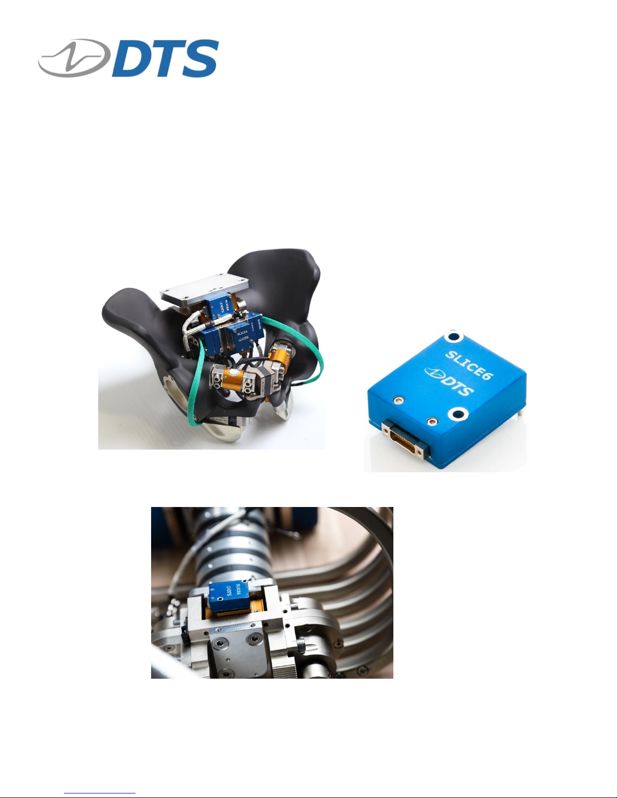
Introducing the SLICE6 DAS
The SLICE6 DAS is an ultra-small, low-power, high-shock-rated, data acquisition system
ideal for in-dummy and test applications with tight space constraints. Each unit contains a
system microprocessor, flash memory for data storage, PTPv2 Ethernet communications
support, and 6 analog sensor input channels supporting conventional bridge (piezo-resistive
and voltage) sensors, each with isolated excitation, high impedance differential input
amplifier, and automatic sensor identification circuits. Units can be interconnected (daisychained) via the communication bus connector.
• Sample rates up to 400,000 sps on 6 channels simultaneously.
• Shock rated to 2000 g for dynamic testing environments.
• 6-channel analog sensor interface supports accelerometers, load cells, pressure
sensors, strain gage and piezo-resistive bridges, and voltage inputs.
• Thermocouples, 1/4 bridges and other sensor types are supported with adapters as
needed.
• LED indicator for system status.
• Ethernet PTPv2 communications (IEEE1588) and sensor ID easily support test set-
ups daisy-chaining hundreds of channels.
Connector information, pin assignments and mechanical specifications can be found in
Appendix A. Common sensor wiring schematics are shown in Appendix B. Please see your
packing list for your hardware’s specifications.
Sensor Interface
The SLICE6 DAS supports 6 sensor measurement channels and is available with a single
connector that supports all sensor signals. See Appendix A for sensor connector pin
assignments.
Sensor interface
connector
Communication bus
Sensor alignment
guide pins
Page 6
SLICE6 DAS User’s Manual June 2018
support.dtsweb.com 6 13006-90010-MAN (Rev. 0)
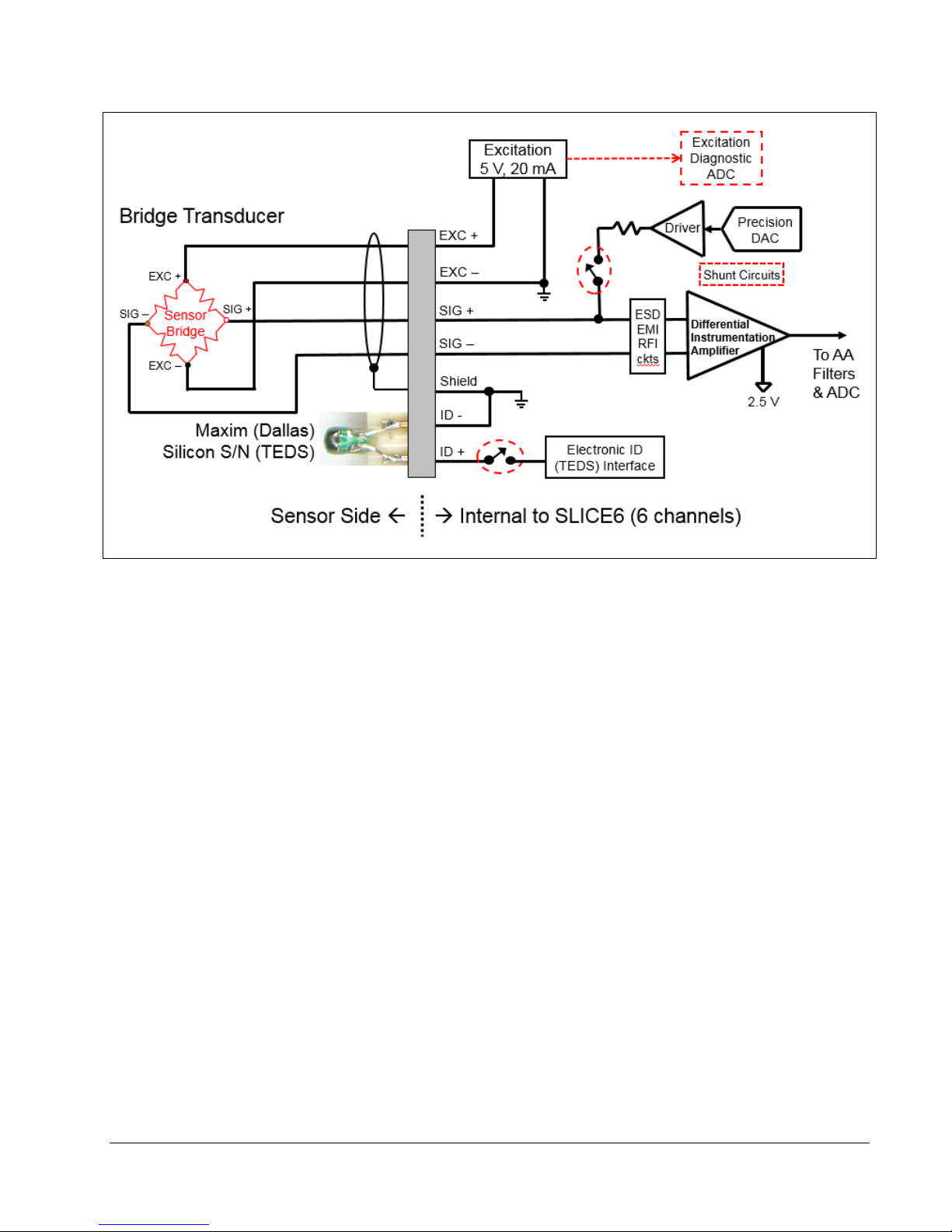
SLICE6 DAS Sensor Interface
Supported Sensor Types
Supplying 5 V excitation up to 20 mA per channel, the SLICE6 DAS supports many types of
sensors including accelerometers, load cells and pressure sensors. The following general
sensor types are supported:
• Full- (4-wire) or half-bridge (2- or 3-wire) resistive and piezo-resistive types.
• Voltage input range: 0.1 to 4.9 V; larger ranges supported with range expander cable.
• Conditioned sensors with 5 V excitation and 2.5 V centered signal output.
For additional questions regarding supported sensors, please contact DTS and provide the
sensor manufacturer and model number, if available. For specific implementation
schematics, see Appendix B.
Input Range
The nominal sensor input range is -2.4 V to +2.5 V (2.5 V center with respect to -Ex) at a
gain of 1. At higher gains, the maximum range decreases correspondingly. For example, at
a gain of 10, the input range is ±240 mV. (The software will automatically calculate the gain
based on the user-specified input range and other sensor parameters.)
Excitation Sources
The excitation source for each sensor measurement channel is individually regulated.
Excitation sources are not turned on until the software initializes the system during
diagnostics. The excitation is fixed at 5.0 V.
2018 Diversified Technical Systems, Inc. All Rights Reserved.
Page 7

SLICE6 DAS User’s Manual June 2018
support.dtsweb.com 7 13006-90010-MAN (Rev. 0)
Bridge Completion
Half-bridge emulation for any channel may be selected via software. Half-bridge transducers
should be connected to ±Ex and -Sig.
Hardware Filters
Each measurement channel has a fixed frequency, 4-pole Butterworth anti-aliasing filter.
There are a variety of hardware filters available, including 500 Hz, 1000 Hz, 1500 Hz,
2500 Hz, 3000 Hz, 10 kHz and 20 kHz. Should you have any questions regarding the best
filter option for your application, please contact DTS.
Offset Compensation
Each channel can compensate for a sensor offset of up to 100% of the full-range output of a
sensor. The sensor offset is measured and the hardware compensation is adjusted during
the diagnostic check. Please see the software manual for additional information.
Electronic Identification (EID)
Each measurement channel supports communication with silicon serial number devices
manufactured by Dallas Semiconductor/Maxim Integrated Products (model DS2401). When
an ID chip is connected to the proper pins on the sensor connector, the software can
automatically read these devices and correlate the serial number to channel set-up
information stored in the sensor database.
Shunt Emulation
The SLICE6 DAS contains a shunt emulation circuit, effectively eliminating the need for
conventional shunt resistors to perform shunt checks. When “Emulation” is chosen as the
shunt calibration method, the software injects a precisely-calculated current into the sensor
to create an expected deflection of the sensor's output. Expected versus actual deflection
are compared to validate that the channel is working properly. Please see the software
manual for additional information.
Communication Bus
All communications, control signals and input power are provided
via the 21-socket, Nano-D communication bus connector. It is also
used to interconnect (daisy-chain) multiple units for hundreds of
test channels. See Appendix A for pin assignments.
Communication Method
The SLICE6 DAS supports Ethernet PTPv2 communications (IEEE1588). PTP (Precision
Timing Protocol) provides standards for precision clock synchronization for measurement
and control systems via Ethernet network communications. Timing information is extracted
from the network’s master clock and used by the SLICE6 DAS to adjust their internal (local)
clock, providing precision timing for high channel-count systems with a sampling
synchronization better than 10 µs. Communication is enabled after the initialization
sequence has completed (15-30 seconds after sufficient power is applied).
Page 8

SLICE6 DAS User’s Manual June 2018
support.dtsweb.com 8 13006-90010-MAN (Rev. 0)
LED
The SLICE6 DAS has a single LED indicator that shows system status.
LED behavior is summarized below.
Priority*
Condition
1
Idle; not connected
(0.5 Hz)
2
Idle; connected
3
Communicating; idle or real-time
(single flash when command received)
4
Idle (connected or not connected; low or high power)
(0.5 Hz)
5
Arming or armed; not recording
6
Armed; recording
7
Armed; faulted or triggered
N/A
Booting bootloader
(5 Hz)
N/A
Booting firmware
N/A
Network DHCP initialization (during DHCP
negotiation with server; time out after 30 seconds)
(2 Hz)
* Higher priority will override the lower priority LED state.
Note: There is no post-event indication. The LED transitions automatically based on condition.
Page 9

SLICE6 DAS User’s Manual June 2018
support.dtsweb.com 9 13006-90010-MAN (Rev. 0)
Data Memory Size
With 15 GB of flash memory available for data storage, the SLICE6 DAS can record
~52 minutes of data at the maximum sampling rate (6 channels at 400 ksps). Since the
recording capacity is very large, it is generally best to limit sampling rates and event durations
to the minimum necessary to avoid large and cumbersome data files. Large files take longer
to download and may also be time-consuming to post-process or difficult to share. Use of
the Region of Interest (ROI) download can save a great deal of time if implemented properly.
Sampling Rates
User-selectable sampling rates are available from 2,000 sps to 400,000 sps.
# of
Channels*
Maximum Sampling Rate
(per channel)
6
400,000 samples per second (sps)
* All channels are recorded even if they are not programmed.
With 15 GB available for data storage, there are 7,500 M samples available (1 sample =
2 bytes). To determine the maximum recording time, divide the number of samples by the
product of the sampling rate and the number of channels.
7,500,000,000
= # of seconds
Sampling rate (sps) X # of channels
Example: 6 channels of data at 400,000 sps
7,500,000,000
= 3,125 sec (52 minutes)
400,000 X 6
Circular Buffer Limitations
Due to the nature of flash memory, the system cannot be armed in Circular Buffer mode
indefinitely. To determine the maximum time available, use the equation below:
0.8 recording time = maximum time available in Circular Buffer mode
Example: 0.8 3,125 sec = 2500 sec (41 minutes)
In this example, the test must occur within 41 minutes, after which time the unit stops
recording data.
Page 10

SLICE6 DAS User’s Manual June 2018
support.dtsweb.com 10 13006-90010-MAN (Rev. 0)
Basic Care and Handling
SLICE6 systems are precision devices designed to operate reliably in dynamic testing
environments. Though resistant to many environmental conditions, care should be taken not
to subject the units to harsh chemicals, submerge it in water, or drop it onto any hard surface.
WARNING:
Electronic equipment dropped from desk height onto a solid
floor may experience up to 10,000 g. Under these conditions,
damage to the exterior and/or interior of the unit is likely.
Your SLICE6 DAS module is supplied with calibration data from the factory. DTS
recommends annual recalibration to ensure that the unit is performing within factory
specifications. The SLICE6 DAS is not user-serviceable and should be returned to the
factory for service or repair.
When not in use or if shipping is required, we suggest that you always recover the connectors
using the plugs provided and place the unit in the padded container originally provided with
your unit.
Shock Rating
Each SLICE6 DAS is rated for 500 g, 3 ms or 2000 g, 0.8 ms half-sine duration, in all axes.
Mounting Considerations
SLICE6 equipment should be bolted securely to the test vehicle or dynamic testing device to
provide the best shock protection. Mounting methods and hardware selection should be
carefully calculated to withstand expected shock loading and facilitate proper grounding.
Check bolt tightness periodically to ensure that 1) the unit is securely fastened to the
baseplate, and 2) the baseplate is securely fastened to the testing platform.
DTS strongly recommends that all equipment be properly grounded to minimize any risk of
data noise due to high-current transients. The test vehicle or dynamic testing device should
be connected to earth ground. SLICE6 equipment should be grounded to each other and
bolted to the test vehicle. DTS recommends checking continuity between the enclosures of
each unit to confirm resistance readings of <1 ohm.
Thermal Considerations
The SLICE6 DAS is a low power device and it is unlikely that self-heating will be an issue in
real-world testing if proper mounting methods are observed. Never mount the unit to a
thermally non-conductive surface like wood or plastic. ALWAYS use SLICE6 DAS with a
heat sink. If you are not mounting the system to a structure that will serve this purpose, DTS
offers a heat sink for use with the SLICE6 DAS (see Appendix A). Should you have any
questions about using SLICE in your environment, please contact DTS.
Page 11

SLICE6 DAS User’s Manual June 2018
support.dtsweb.com 11 13006-90010-MAN (Rev. 0)
SLICE6 DAS Maintenance
Periodically inspect 1) the connector contacts for proper alignment or other damage, and 2)
the sealing gasket surrounding the sensor interface connector and adjust if necessary. A
picture of the sensor interface connector and a properly installed gasket
(P/N 89100-19880-R) is shown below.
Power Management
A good power source is of paramount importance. SLICE6 DAS should be powered from a
SLICE6 Distributor. (One SLICE6 Distributor can support up to 4 SLICE6 DAS chains of up
to 10 DAS per chain for a total of 40 DAS or 240 channels.) Be sure to consider any power
drop due to cable length.
Power Consumption
Input Voltage
Deep Sleep
Idle
(On)
Data Download
(On)
Data Collection
(On and Armed)
9-15 VDC1
12 mW
840 mW
900 mW
2.5 W
The SLICE6 DAS does not contain an internal battery and must be connected to external
power at all times for operation. Without external power applied, the SLICE6 DAS is in a
power off state.
With power applied, the DAS is either in deep sleep or on. If the ON signal is absent or
removed, the DAS enters deep sleep, the lowest power consumption state. With the ON
signal applied, power consumption is 840 mW-2.5 W, depending largely on the connected
sensor load and the unarmed/armed state of the unit.
Power-up and Power-down Procedures
When sufficient power is applied, the SLICE6 DAS will power up (on, idle and
communications enabled) if an ON signal is present. If an ON signal is absent, the unit will
initiate a limited power up sequence and immediately enter deep sleep. Power up (On state)
occurs within 15-30 seconds (static IP or DHCP, respectively), after which communication is
enabled. The unit enters deep sleep ~2 seconds after the ON signal is removed.
Power down of the DAS is immediate upon removal of external power. Wait ~30 seconds
before reinitializing the DAS.
1
Commercially-available 9 V batteries should not be used to power the SLICE6 DAS.
Page 12

SLICE6 DAS User’s Manual June 2018
support.dtsweb.com 12 13006-90010-MAN (Rev. 0)
Software
Both SLICEWare and DataPRO software applications support the SLICE6 DAS.
Minimum PC Specifications
Parameter
SLICEWare
DataPRO
Operating system
Windows 7, 8 or 10.
32- and 64-bit
Windows 7, 8 or 10.
32- and 64-bit
Processor
1 GHz
Multicore
RAM
2 GB*
4 GB; 8 GB recommended*
Hard drive disk space
100 MB + more for test data
250 MB + more for test data
Screen resolution
1024 x 768
1024 x 768
* More RAM is important for high channel counts and longer/higher sample rates.
Data Collection Concepts
The discussion below provides a general introduction to data collection. Please see the
software manual for a detailed discussion and implementation specifics.
The SLICE6 DAS is a standalone data logger. Once the system is armed, the PC can be
disconnected if desired. After receiving a Start Record or Event signal, SLICE autonomously
collects data, storing it to flash memory with no user interaction. After the test, the user
reconnects the PC to download the data.
There is also a real-time mode in the control software that allows the user to check channel
inputs on an oscilloscope-looking screen. (This data can be logged.)
Data Collection Modes
The SLICE6 DAS supports 4 data collection modes: Circular Buffer, Recorder, Hybrid
Recorder, and Continuous Recorder. (Note: The software cannot simultaneously display
the data while the system is recording.)
Circular Buffer Mode
Using Circular Buffer mode, the user can program the SLICE6 DAS to record pre- and postEvent data. Time Zero (T=0) is marked when the Event signal is received.
Due to the nature of flash memory, the system cannot be armed in Circular Buffer mode
indefinitely. Please see page 9 for information on how to calculate data storage duration
when using Circular Buffer mode.
Recorder Mode
Data collection begins when a Start Record signal is received and continues for the time
specified in the test set-up. If an Event signal is received sometime after the Start Record
signal, this is marked as T=0.
Page 13

SLICE6 DAS User’s Manual June 2018
support.dtsweb.com 13 13006-90010-MAN (Rev. 0)
Hybrid Recorder Mode
Data collection begins when a Start Record signal is received and continues until the unit
receives an Event signal. The unit then records for the post-Event time specified by the user.
The Event signal marks the T=0 point and all data recorded is available for download.
Continuous Recorder Mode
Data collection begins when a Start Record signal is received and continues until the Start
Record signal is released. The unit will then re-arm for another event. The LEDs on the unit
will flash blue slowly then rapidly, and then the status LED will become solid blue, indicating
the unit is fully armed. The unit will continue to record new events until it records the number
of events specified by the user. If an Event signal is received after the unit has re-armed,
the unit will disarm and no longer attempt to re-arm.
NOTE:
An event or trigger signal applied anywhere in the SLICE6 DAS
chain is distributed throughout the DAS chain and forwarded
to the SLICE6 Distributor, but is NOT exported outside the
SLICE6 Distributor. This also applies to level trigger.
Start Record and Event Initiation
The SLICE6 DAS supports multiple methods of initiating Start Record and Event signals.
Typically, Start Record and Event are initiated via an external hardware interface that
provides a discrete contact closure (CC) signal to initiate recording (Recorder mode) or mark
T=0 (Circular Buffer mode).
All SLICE6 DAS data collection modes support multi-event arming. A unit armed in a
multiple-event mode will re-arm when an event completes. The unit will stop re-arming when
the number of events specified by the user has been recorded.
SLICE6 DAS can be placed in an auto-arm mode that will cause the unit to arm automatically
when the power is cycled. This available with any available data collection mode.
Additionally, Circular Buffer mode supports level triggering. This method continuously
samples the incoming data and begins data collection if the data is above or below predefined
levels. For example, it might be useful to begin data collection when a certain accelerometer
experiences a force above 200 g. Using level trigger and Circular Buffer mode, SLICE6 DAS
can support this or any level-trigger signal on any channel.
CAUTION:
Level trigger is NOT recommended when SLICE6 DAS is used
for in-dummy testing.
Page 14

SLICE6 DAS User’s Manual June 2018
support.dtsweb.com 14 13006-90010-MAN (Rev. 0)
Finally, if the SLICE6 DAS remains connected to the PC during data collection, the control
software can be used to initiate data collection.
The table below summarizes the data collection modes and event/triggering options.
Supports T=0
Start Record
T=0 methods
supported
Data record window
Circular Buffer
Yes
Hardware (CC),
software (PC) or
level trigger
User-defined pre- and post- T=0
durations
Recorder
Yes
Hardware (CC),
software (PC) or
level trigger
User-defined duration after T=0
Hybrid Recorder
Yes
Hardware (CC),
software (PC) or
level trigger
User-defined post-Event duration
Continuous
Recorder
Yes
Hardware (CC),
software (PC), or
level trigger
User-defined duration after T=0,
with recording multiple events
possible
Page 15

SLICE6 DAS User’s Manual June 2018
support.dtsweb.com 15 13006-90010-MAN (Rev. 0)
Appendix A: Hardware Specifications
Connector Information and Pin Assignments
Communication Bus Connector
(Omnetics A29100-021)
(looking into the connector)
Pin
Function
1
/ON (contact closure input to ground)
2
/START (contact closure input to ground)
3
/EVENT (contact closure input to ground)
4
Status output (5 V via 10K with respect to ground)
5
No connection
6
Ground
7
VDC input
8
Ground
9
VDC input
10
Ground
11
VDC input
12
Ethernet Rx1 (-)
13
Ethernet Rx1 (+)
14
Ethernet Tx1 (-)
15
Ethernet Tx1 (+)
16
Ground
17
Ground
18
Ethernet Rx2 (-)
19
Ethernet Rx2 (+)
20
Ethernet Tx2 (-)
21
Ethernet Tx2 (+)
1
11
12
21
Page 16

SLICE6 DAS User’s Manual June 2018
support.dtsweb.com 16 13006-90010-MAN (Rev. 0)
Sensor Interface Connector
(Omnetics A79047-001)
(looking into the connector)
Suggested mating connector P/N:
Omnetics A79046-x01 (DTS P/N 80000-04063(-R))
Pin
Function
Pin
Function
1
No connection
19
No connection
2
+Ex (Ch 4)
20
+Sig (Ch 2)
3
+Sig (Ch 4)
21
-Sig (Ch 2)
4
-Sig (Ch 4)
22
-Ex (Ch 2)
5
-Ex (Ch 4)
23
+ID (Ch 5)
6
+Ex (Ch 1)
24
+ID (Ch 2)
7
+Sig (Ch 1)
25
+Ex (Ch 6)
8
-Sig (Ch 1)
26
+Sig (Ch 6)
9
-Ex (Ch 1)
27
-Sig (Ch 6)
10
+ID (Ch 4)
28
-Ex (Ch 6)
11
-ID (Ch 4, 5, 6)
29
+Ex (Ch 3)
12
+ID (Ch 1)
30
+Sig (Ch 3)
13
-ID (Ch 1, 2, 3)
31
-Sig (Ch 3)
14
+Ex (Ch 5)
32
-Ex (Ch 3)
15
+Sig (Ch 5)
33
+ID (Ch 6)
16
-Sig (Ch 5)
34
+ID (Ch 3)
17
-Ex (Ch 5)
35
Reserved
18
+Ex (Ch 2)
36
Ground
1
19
20
36
Page 17

A
B
C
D
A
B
C
D
8
7
6
5
4 3
2
1
8
7
6
5
4 3 2 1
MDL:
DTS_SLICE6
DATE:
SEAL BEACH, CA 90740
562-493-0158
www.dtsweb.com
MATERIAL:
UNLESS OTHERWISE SPECIFIED:
UNITS = MM [INCH]
DIMENSIONAL TOLERANCES
.254 [0.010"]
INTERPRET PER ASME Y14.5. DO NOT SCALE.
SCALE:
SIZE:
SHEET:
DRAWN:
DTS P/N:
DESCRIPTION:
REV:
1 OF 2
This drawing contains information that is the property of Diversified Technical Systems, Inc. (DTS).
All copyright, patent, and ownership rights are retained. This information shall not be disclosed,
reproduced in whole or in part, or used for manufacture without prior written consent from DTS.
INTELLECTUAL PROPERTY STATEMENT
REV ZONE DESCRIPTION DATE BY
B
2,4 .094[ ]
0 .000[ ]
21,6 .850[ ]
30 1.181[ ]
32,05 1.262[ ]
2,4 .094[ ]
0 .000[ ]
21,6 .850[ ]
24 .945[ ]
CONN
13,5 .531[ ]
3,25 .128[ ]
0 .000[ ]
(4X) R1 [.039]
2X R0,5 [.020]
(2X)
2,7 [.106] .005" THRU
MOUNT USING (2X) M2.5 SCREWS
TORQUE TO 1.2 N-M CLEAN & DRY
1,05 [.041]
+0.000 -0.005"
CONN 6,8 .268[ ]
0 .000[ ]
10,5 .413[ ]
.015"13 .512[ ]
CONN
2 .079[ ]
0 .000[ ]
22,7 .894[ ]
1,3 .051[ ]
0 .000[ ]
1,3 .051[ ]
0 .000[ ]
22,7 .894[ ]
9,2 .362[ ]
0 .000[ ]
CONN
12 .472[ ]
Pin Signal
1 2 +EXCIT-CH4
3 +SIG-CH4
4 -SIG-CH4
5 -EXCIT-CH4
6 +EXCIT-CH1
7 +SIG-CH1
8 -SIG-CH1
9 -EXCIT-CH1
10 +ID-CH4
11 -ID-CH4,5,6
12 +ID-CH1
13 -ID-CH1,2,3
14 +EXCIT-CH5
15 +SIG-CH5
16 -SIG-CH5
17 -EXCIT-CH5
18 +EXCIT-CH2
19 20 +SIG-CH2
21 -SIG-CH2
22 -EXCIT-CH2
23 +ID-CH5
24 +ID-CH2
25 +EXCIT-CH6
26 +SIG-CH6
27 -SIG-CH6
28 -EXCIT-CH6
29 +EXCIT-CH3
30 +SIG-CH3
31 -SIG-CH3
32 -EXCIT-CH3
33 +ID-CH6
34 +ID-CH3
35 TEMP-VDC
36 Earth (GND)
SLICE6 DAS,
MOUNTING DRAWING
2
G NEWTON
2016-09-20
2:1
2 P/N, DRAWING FORMAT 2017-08-28 GN
6061-T6 ALUMINUM HOUSING
W/ BLUE ANODIZE
NOTES:
1. MASS: 15 GRAMS
3 GRAMS
2. SLICE6 SENSOR CONNECTOR: OMNETICS P/N A79047-001 (NSD-36-DD-GS)
MATES WITH: OMNETICS P/N A79046-001 (NPD-36-DD-GS)
3. SLICE6 CHAIN CONNECTOR: OMNETICS P/N A29100-021 (MNSO-21-AA-N-ETH-M)
SENSOR CONNECTOR
PIN ASSIGNMENTS
P1
P19
P36
P20
SENSOR CONNECTOR
(2X) M1.5 DOWEL PINS
CHAIN CONNECTOR
SERIAL NUMBER
PREFIX: SL6
STATUS LED
CONNECTOR
SEALING GASKET
Page 18

SLICE6 DAS User’s Manual June 2018
support.dtsweb.com 18 13006-90010-MAN (Rev. 0)
Accessories/Support Equipment
13006-90060: SLICE6 Sensor Interface 2.0
13006-90070: SLICE6 Sensor Connector Kit, 1-Channel
13006-90080: SLICE6 Sensor Connector Kit, 2-Channel
13006-90090: SLICE6 Sensor Connector Kit, 3-Channel
13006-90110: SLICE6 1 Ch Sensor Cable Assembly (+ ID, pigtails; 1 ft)
13006-90320: SLICE6 Distributor (18-36 V input range)
13006-90321: SLICE6 Distributor for THOR (13-36 V input range)
13006-90420: SLICE6 Distributor (Gen2)
80000-04090: Conn assy; 21-pin plug to pigtails, 30 AWG, 18" (mates with comm bus)
89100-19880-R: SLICE6 DAS sealing gasket
89100-14480-R: Heat sink, SLICE MICRO/NANO/SLICE6; base plate
Page 19

SLICE6 DAS User’s Manual June 2018
support.dtsweb.com 19 13006-90010-MAN (Rev. 0)
Appendix B: Sensor Interface Wiring Diagrams
Signal Generator
2018 Diversified Technical Systems, Inc. All Rights Reserved.
Page 20

Page 21

SLICE6 DAS User’s Manual June 2018
support.dtsweb.com 21 13006-90010-MAN (Rev. 0)
Revision History
Rev
Date
By
Description
0
4 June 2018
EK
Initial release.
 Loading...