

Page 1
13006-90320-MAN (Rev. 0) © Diversified Technical Systems, Inc. All Rights Reserved.
SLICE6 Distributor
(18-36 V input, 15 V output)
User’s Manual
September 2018
Page 2

SLICE6 Distributor (18-36 V input, 15 V output) User’s Manual September 2018
support.dtsweb.com ii 13006-90320-MAN (Rev. 0)
Table of Contents
DTS Support ....................................................................................................................... 3
Introducing the SLICE6 Distributor .................................................................................. 4
Connector Panel ................................................................................................................. 4
BATTERY Connector ....................................................................................................... 5
UP Connector .................................................................................................................. 5
Communication Method ............................................................................................... 5
SLICE6 DAS Connectors (DN-1 through DN-4) ............................................................... 6
AUX Connector ................................................................................................................ 6
LEDs .................................................................................................................................... 7
Basic Care and Handling ................................................................................................... 8
Shock Rating .................................................................................................................... 8
Mounting Considerations ............................................................................................. 8
Thermal Considerations ................................................................ ................................ ... 8
Power Management ............................................................................................................ 9
Power-up and Power-down Procedures .......................................................................... 9
Software ............................................................................................................................ 10
Appendix A: Connector Information .............................................................................. 11
Appendix B: Mechanical Specifications ........................................................................ 15
Accessories/Support Equipment .................................................................................... 16
Appendix C: Hardware Configuration Specifications .................................................. 17
Using the SLICE Network Configuration Utility .............................................................. 17
Appendix D: Declaration of CE Conformity .................................................................. 20
Page 3

SLICE6 Distributor (18-36 V input, 15 V output) User’s Manual September 2018
support.dtsweb.com 3 13006-90320-MAN (Rev. 0)
DTS Support
SLICE systems are designed to be reliable and simple to operate. Should you need
assistance, DTS has support engineers worldwide with extensive product knowledge and
crash test experience to help via telephone, e-mail or on-site visits.
The best way to contact a DTS support engineer is to submit a request through the DTS Help
Center web portal (support.dtsweb.com). You must be registered
(support.dtsweb.com/registration) to submit a request (https://support.dtsweb.com/hc/en-
us/requests/new). Registration also enables access to additional self-help resources and
non-public support information.
This manual supports the following products:
13006-90320: SLICE6 Distributor (18-36 V input, 15 V output)
Page 4

SLICE6 Distributor (18-36 V input, 15 V output) User’s Manual September 2018
support.dtsweb.com 4 13006-90320-MAN (Rev. 0)
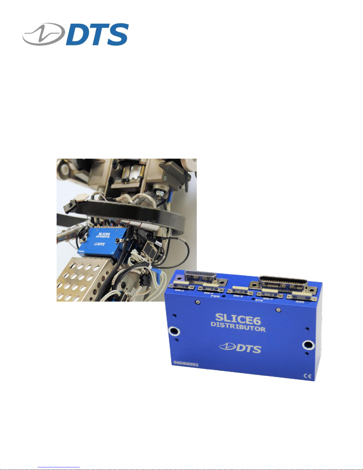
Introducing the SLICE6 Distributor
The SLICE6 Distributor is a centralized power and communications management hub
suitable for use in dynamic testing environments. Designed for in-dummy use, it supports up
to 40 SLICE6 DAS modules (240 channels), primary input power distribution, an external
back-up battery, PTPv2 Ethernet communications, and status, control and event signals.
• Shock rated for 500 g for dynamic testing environments.
• Supports 1 Gb Ethernet and PTPv2 communications (IEEE1588).
• 4 SLICE6 DAS ports support up to 10 SLICE6 DAS per connector.
• Main power and dedicated battery input connector supports primary and back-up
power inputs.
• Internal temperature sensor.
• LED indicators for power and system status.
• Dedicated connector supports external ID/status tag and 4 temperature sensors.
Appendix A contains connector information and pin assignments. Appendix B details the
unit’s mechanical specifications. Appendix C provides information on the network
parameters of your equipment.
Connector Panel
All connectors and LED indicators are accessible from the front panel. The BATTERY
connector supports an external back-up battery. The UP connector supports primary input
power, external communications, status, control and event signals. Connectors DN-1
through DN-4 support SLICE6 DAS. The AUX connector supports an external ID/status tag
and 4 temperature sensors. A discussion of the LEDs begins on page 7.
SLICE6 Distributor Connector Panel
The SLICE6 Distributor does not contain an internal battery and must be connected to
external power (main or battery) at all times for operation.
Page 5

SLICE6 Distributor (18-36 V input, 15 V output) User’s Manual September 2018
support.dtsweb.com 5 13006-90320-MAN (Rev. 0)
BATTERY Connector
The BATTERY connector supports use and charging of lithiumion batteries as a back-up power source. Only DTS-supplied
batteries should be used. The battery can be hardware enabled
and a temperature sensor (included in DTS batteries) is also
supported.
The external battery will charge whenever sufficient external power is connected to the UP
connector, however the fastest charge rate is when the SLICE6 Distributor is in a power down
state (i.e., the ON signal is absent). When the ON signal is present, the SLICE6 Distributor
is fully functional, however external power is principally used to support the SLICE6
Distributor and the attached DAS, thus reducing battery charging to a minimum. For information on power requirements, see page 9.
UP Connector
The UP connector supports primary input power and
Ethernet communications. System status, ON and event
signals are also supported via simple contact closure.
Data from the internal temperature sensor may be
monitored and recorded from within the software.
NOTE:
An event or trigger signal forwarded from the SLICE6 DAS
chain to the SLICE6 Distributor is NOT exported outside the
SLICE6 Distributor. This also applies to level trigger.
Level trigger is NOT recommended when SLICE6 DAS is used
in in-dummy testing.
See Appendix A for pin assignments. See Appendix C for the network parameters of your
equipment. For information on power requirements, see page 9.
Communication Method
Ethernet communications between the SLICE6 Distributor and the host PC are supported at
1 Gb. With sufficient power applied and an ON signal present, the SLICE6 Distributor will
power up within 15-30 s (static IP or DHCP, respectively), after which communication is
enabled.
The SLICE6 Distributor supports Ethernet PTPv2 communications (IEEE1588 compliant).
PTP (Precision Timing Protocol) provides standards for precision clock synchronization for
measurement and control systems via Ethernet network communications. Timing informa-
tion is extracted from the network’s master clock and used by the SLICE6 Distributor to adjust
its internal (local) clock, providing precision timing for high channel-count systems with a
sampling synchronization better than 10 µs.
Page 6
SLICE6 Distributor (18-36 V input, 15 V output) User’s Manual September 2018
support.dtsweb.com 6 13006-90320-MAN (Rev. 0)
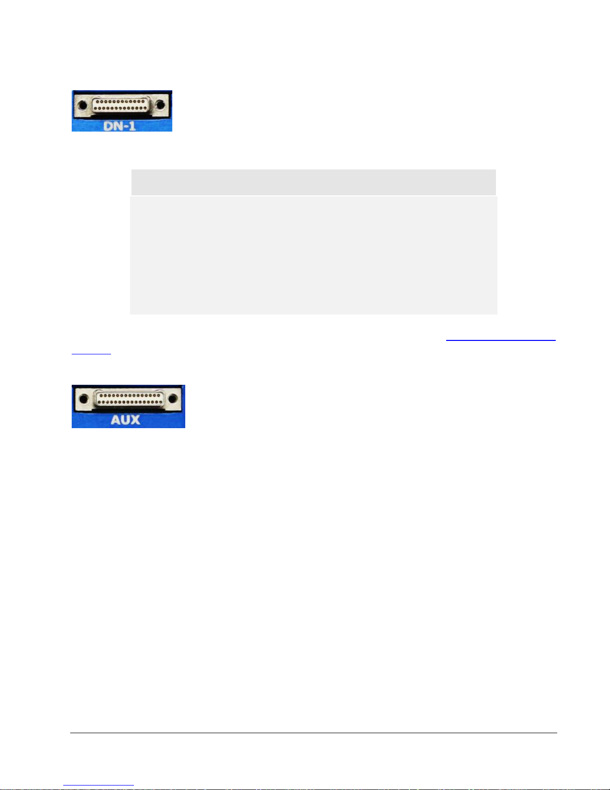
SLICE6 DAS Connectors (DN-1 through DN-4)
These 4 connectors are identical and support output power, Ethernet,
status, start, ON and event signals. Each connector supports up to 10
SLICE6 DAS for a total of 40 DAS or 240 channels. Ethernet
communications between the SLICE6 Distributor and SLICE6 DAS are
supported at 100 Mb.
NOTE:
An event or trigger signal applied anywhere in the SLICE6 DAS
chain is distributed throughout the DAS chain and forwarded
to the SLICE6 Distributor, but is NOT exported outside the
SLICE6 Distributor. This also applies to level trigger.
Level trigger is NOT recommended when SLICE6 DAS is used
in in-dummy testing.
For detailed information on SLICE6 DAS operation, please see the SLICE6 DAS User’s
Manual.
AUX Connector
The AUX connector supports several optional functions including
LED signal mirroring and 4 external temperature sensors. LED signal
support mirrors the PWR and STS LED states, allowing system status
visibility using an external pendant or other indicator when the
SLICE6 Distributor front panel is not visible. Data from external temperature sensors may
be monitored and recorded from within the software.
Page 7
SLICE6 Distributor (18-36 V input, 15 V output) User’s Manual September 2018
support.dtsweb.com 7 13006-90320-MAN (Rev. 0)
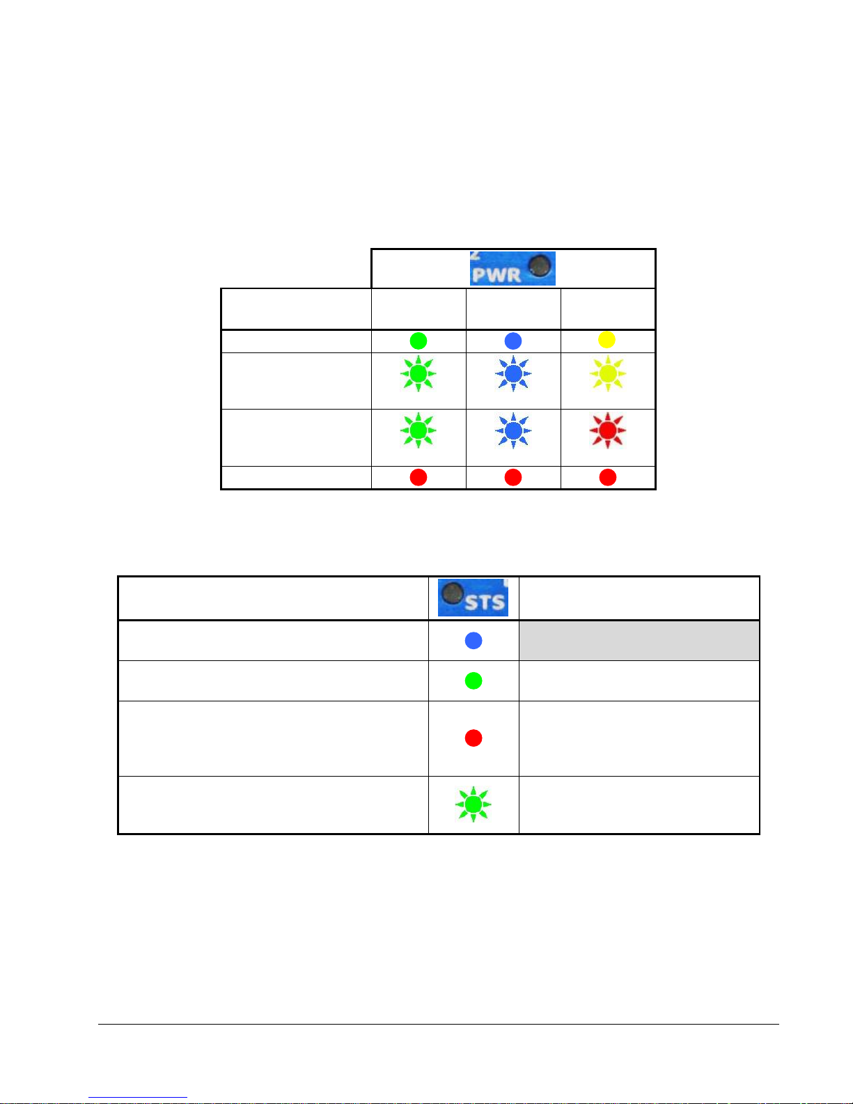
LEDs
There are 2 LED indicators. The STS LED indicates communication and arm status and the
PWR LED indicates power status. At system power-up, the red-green-blue LED initialization
sequence is performed by the STS LED followed by the PWR LED.
LED behavior is summarized below.
External Battery
Capacity1
Charging
when Off
Charging
when On
Discharging
when On
>90%
>50% - <90%
(0.5 Hz)
(0.5 Hz)
(0.5 Hz)
>20% - <50%
(2 Hz)
(2 Hz)
(2 Hz)
<20% –or– fault
1
The SLICE6 Distributor does not contain an internal battery and must
be connected to external power (main input or battery) at all times.
Recorder Mode
Circular Buffer Mode
Armed and waiting for Start Record signal
to begin data collection
Start Record signal received and recording
data; waiting for Event signal (optional)
Armed and recording data;
waiting for Event signal
Event signal received (optional)
–or– fault signal received + data collection
completed (no comm)
–or– fault
Event signal received
–or– fault signal received + data
collection completed (no comm)
–or– fault
Data collection completed,
PC downloading data;
communicating with host
Data collection completed,
PC downloading data;
communicating with host
Page 8

SLICE6 Distributor (18-36 V input, 15 V output) User’s Manual September 2018
support.dtsweb.com 8 13006-90320-MAN (Rev. 0)
Basic Care and Handling
SLICE6 systems are precision devices designed to operate reliably in dynamic testing
environments. Though resistant to many environmental conditions, care should be taken not
to subject the units to harsh chemicals, submerge it in water, or drop it onto any hard surface.
WARNING:
Electronic equipment dropped from desk height onto a solid
floor may experience up to 10,000 g. Under these conditions,
damage to the exterior and/or interior of the unit is likely.
Your unit is supplied with calibration data from the factory. DTS recommends annual
recalibration to ensure that the unit is performing within factory specifications. The SLICE6
Distributor is not user-serviceable and should be returned to the factory for service or repair.
When not in use or if shipping is required, we suggest that you place the unit in the padded
container originally provided with your unit.
Shock Rating
The SLICE6 Distributor is rated for 500 g, 3 ms half-sine duration, in all axes.
Mounting Considerations
SLICE6 equipment should be bolted securely to the test vehicle or dynamic testing device to
provide the best shock protection. Mounting methods and hardware selection should be
carefully calculated to withstand expected shock loading and facilitate proper grounding.
Check bolt tightness periodically to ensure that the unit is securely fastened to the baseplate
or testing platform.
DTS strongly recommends that all equipment be properly grounded to minimize any risk of
data noise due to high-current transients. The test vehicle or dynamic testing device should
be connected to earth ground. SLICE6 equipment should be grounded to each other and
bolted to the test article. DTS recommends checking continuity between the enclosures of
each unit to confirm resistance readings of <1 ohm.
Thermal Considerations
It is unlikely that thermal overload will be an issue in real-world testing if proper mounting
methods are observed and common-sense measures are taken. Never mount the unit to a
thermally non-conductive surface like wood or plastic. ALWAYS use the SLICE6 Distributor
with a heat sink or mount it to a structure that will serve this purpose. When used continuously at the max output level, the unit may get very warm. Since the system draws the most
power when armed, running the calibrations and arming as late as possible will minimize selfheating, particularly in embedded/in-dummy applications. Avoid full power for longer than
30 min and consider monitoring temperatures during extended arming periods. If you have
any questions about using the SLICE6 Distributor in your environment, please contact DTS.
Page 9

SLICE6 Distributor (18-36 V input, 15 V output) User’s Manual September 2018
support.dtsweb.com 9 13006-90320-MAN (Rev. 0)
Power Management
The SLICE6 Distributor should be powered from a high-quality power source with output
voltage and current ratings appropriate for the installation. A flashing PWR LED (any color)
or a solid green, blue or yellow LED means voltage and current input levels are within
specifications and polarity is correct. (A discussion of the PWR LED begins on page 7.) Be
sure to consider any power drop due to cable length.
One SLICE6 Distributor can support up to 4 SLICE6 DAS chains of up to 10 DAS per chain
for a total of 40 DAS or 240 channels.
Output Power vs. Power Input Source
Power Consumption
Input Power
Specs
On (min)
On (max)
18-36 VDC
12 A (max)
216 W (max)
15 VDC, 2.1 A (max)
per DAS connector
4 A (max)* to charge
external battery**
9-12.75 VDC, 2.3 A (max)
per DAS connector
6 W***
216 W****
* Max charge rate is only possible when the SLICE6 Distributor is in a power down state (i.e., the ON signal is absent)
** For use with DTS-supplied, lithium-ion batteries only
*** No DAS or battery attached + ON signal present
**** System is fully functional + armed and powering 40 SLICE6 DAS + charging battery (charging reduced to 50 mW)
The SLICE6 Distributor does not contain an internal battery and must be connected to
external power at all times for operation. Without external power applied (main or battery),
the SLICE6 Distributor is in a power off state.
With external power applied, only battery charging is enabled (4 A maximum) when the ON
signal is absent. Without a battery or DAS connected and with the ON signal present, the
unit consumes the least power (6 W). The maximum power consumed/dissipated is 216 W
when the unit is fully functional, the system is fully armed and powering 40 SLICE6 DAS, and
charging an external battery.
The external battery will charge whenever sufficient external power is connected to the UP
connector, however the fastest charge rate is when the SLICE6 Distributor is in a power down
state (i.e., the ON signal is absent). When the ON signal is present, the SLICE6 Distributor
is fully functional, however external power is principally used to support the SLICE6
Distributor and the attached DAS, thus reducing battery charging to a minimum (50 mW).
Power-up and Power-down Procedures
With sufficient power applied, the SLICE6 Distributor will power up (enable control system
electronics, communications, output power and battery charging) when an ON signal is present. If an ON signal is absent, only battery charging is enabled. Power up (on state) occurs
within 15-30 s (static IP or DHCP, respectively), after which communication is enabled.
Power down is immediate upon removal of external power. Wait ~30 s before reinitializing
the system.
Page 10

SLICE6 Distributor (18-36 V input, 15 V output) User’s Manual September 2018
support.dtsweb.com 10 13006-90320-MAN (Rev. 0)
Software
Currently, only DataPRO software supports the SLICE6 Distributor. Additionally, the
operation of your system depends greatly on the features and functionality of the DAS and
support equipment available to you. Please see the DataPRO software manual and your
equipment user’s manuals for detailed discussions and implementation specifics.
Minimum PC Specifications
Parameter
DataPRO
Operating system
Windows Vista, 7, 8 or 10.
32- and 64-bit
Processor
Multicore
RAM
4 GB; 8 GB recommended*
Hard drive disk space
250 MB + more for test data
Screen resolution
1920 x 1080; 1366 x 768
* More RAM is important for high channel counts and longer/higher sample rates.
Page 11

SLICE6 Distributor (18-36 V input, 15 V output) User’s Manual September 2018
support.dtsweb.com 11 13006-90320-MAN (Rev. 0)
Appendix A: Connector Information
External BATTERY Connector*
(Omnetics A98081-025)
(looking into the connector)
Pin
Function
1
-VDC input from external battery
2
-VDC input from external battery
3
-VDC input from external battery
4
-VDC input from external battery
5
-VDC input from external battery
6
+VDC input from external battery
7
+VDC input from external battery
8
+VDC input from external battery
9
+VDC input from external battery
10
+VDC input from external battery
11
Battery 1 temp sensor (reference to Ground)
12
Battery 2 temp sensor (reference to Ground)
13
Ground
14
-VDC input from external battery
15
-VDC input from external battery
16
-VDC input from external battery
17
-VDC input from external battery
18
-VDC input from external battery
19
+VDC input from external battery
20
+VDC input from external battery
21
+VDC input from external battery
22
+VDC input from external battery
23
+VDC input from external battery
24
Battery 1 enable (reference to Ground)
25
Battery 2 enable (reference to Ground)
* For use with DTS-supplied batteries only.
25 1 13
14
Page 12

SLICE6 Distributor (18-36 V input, 15 V output) User’s Manual September 2018
support.dtsweb.com 12 13006-90320-MAN (Rev. 0)
UP Connector
(Omnetics A99116-037)
(looking into the connector)
Suggested mating connector P/N:
A98101-037 (includes jack screws and 18” pigtails)
Pin
Function
Pin
Function
1
Ground
20
Ground
2*
Ethernet TxRxA (+)
21*
Ethernet TxRxA (-)
3*
Ethernet TxRxB (+)
22*
Ethernet TxRxB (-)
4*
Ethernet TxRxC (+)
23*
Ethernet TxRxC (-)
5*
Ethernet TxRxD (+)
24*
Ethernet TxRxD (-)
6
/ON (contact closure input to Ground)
25
Start recording input
(apply 5 V with respect to pin 7)
7
Common for start record
8 Event - (contact closure to pin 26)
26
Event + (contact closure to pin 8)
9
Ground
27
Status (reference to Ground)
10
Ground
28
Ground
11
Ground
29
Ground
12
Ground
30
Ground
13
Ground
31
Ground
14
Ground
32
Ground
15
Reserved
33
Ground
16
VDC input
34
VDC input
17
VDC input
35
VDC input
18
VDC input
36
VDC input
19
VDC input
37
VDC input
* All signals required for Ethernet comm.
WARNING:
Do not apply external voltages to the event, communication,
status or ON signals—this could result in damage to the unit.
20
19 1 37
Page 13

SLICE6 Distributor (18-36 V input, 15 V output) User’s Manual September 2018
support.dtsweb.com 13 13006-90320-MAN (Rev. 0)
SLICE6 DAS Connectors (DN-1 through DN-4)
(Omnetics A38100-825)
(looking into the connector)
Suggested mating connector P/N:
A29000-125 (includes jack screws and 18” pigtails)
Pin
Function
1
/ON-DAS (contact closure input to Ground)
2
No connection
3
STATUS-DAS
4
/START-DAS (contact closure input to Ground)
5
No connection
6
/EVENT-DAS (contact closure input to Ground)
7
Ground
8
STATUS-HUB
9
Ground
10
Ground
11
VDC output
12
VDC output
13
Ground
14
Ethernet Tx (+)
15
Ethernet Tx (-)
16
Ethernet Rx (+)
17
Ethernet Rx (-)
18
No connection
19
No connection
20
No connection
21
No connection
22
Ground
23
Ground
24
VDC output
25
VDC output
1
25
14
13
Page 14

SLICE6 Distributor (18-36 V input, 15 V output) User’s Manual September 2018
support.dtsweb.com 14 13006-90320-MAN (Rev. 0)
AUX Connector
(Omnetics A38100-831)
(looking into the connector)
Suggested mating connector P/N:
A29000-131 (includes jack screws and 18” pigtails)
Pin
Function
1
Ground
2
Temp sensor clock (1)
3
Temp sensor clock (2)
4
Temp sensor clock (3)
5
Ground
6
Temp sensor data (1)
7
Temp sensor data (2)
8
Temp sensor data (3)
9
No connection
10
Ground
11
STS LED, blue (cathode)
12
Ground
13
STS LED, red (cathode)
14
No connection
15
STS LED, green (cathode)
16
Ground
17
Temp sensor 1 VDC
18
Temp sensor 1 enable
19
Temp sensor clock (4)
20
Temp sensor 2 VDC
21
Temp sensor 2 enable
22
Temp sensor data (4)
23
Temp sensor 3 VDC
24
Temp sensor 3 enable
25
Temp sensor 4 VDC
26
Temp sensor 4 enable
27
LED VDC (anode for STS LED)
28
LED VDC (anode for PWR LED)
29
PWR LED, red (cathode)
30
PWR LED, green (cathode)
31
PWR LED, blue (cathode)
1
31
17
16
Page 15

A
B
C
D
A
B
C
D
8
7
6
5
4 3
2
1
8
7
6
5
4 3 2 1
MDL:
SLICE6-DB
DATE:
SEAL BEACH, CA 90740
562-493-0158
www.dtsweb.com
MATERIAL:
FINISH:
UNLESS OTHERWISE SPECIFIED
DIMENSIONAL TOLERANCES ARE:
DECIMAL
.X
.XX
.XXX
INCHES
.02
.01
.005
ANGLES
.25
DO NOT SCALE. INTERPRET PER ASME Y14.5
SCALE:
SIZE:
SHEET:
DRAWN:
DTS P/N:
DESCRIPTION:
UNITS:INCH
63
Manufacture/fabricate to meet the EU RoHS Directive
2011/65/EU and RoHS Annex II phthalates
RoHS
REMOVE BURRS & BREAK SHARP EDGES
DIMENSION LIMITS APPLY AFTER PLATING
REV:
1 OF 1
This drawing contains information that is the property of Diversified Technical Systems, Inc. (DTS).
All copyright, patent, and ownership rights are retained. This information shall not be disclosed,
reproduced in whole or in part, or used for manufacture without prior written consent from DTS.
INTELLECTUAL PROPERTY STATEMENT
REV ZONE DESCRIPTION DATE BY
B
85 [3.346]
52 [2.047]
25 [.984]
58 [2.268]
26 [1.024]
77 [3.032]
MOUNTING HOLES
4,3 [.1690] THRU
*USE M4 X 35L SHCS
OR #8 X 1.375"L SHCS
SLICE6 DISTRIBUTOR,
MOUNTING DRAWING
0
J CASEY
2017-07-18
1.5:1
0 ORIGINAL RELEASE 2017-07-18 JC
6061-T6 ALUMINUM
WEIGHT: 185 GRAMS
SCALE 1.000
(1X) OMNETICS
P/N A28100-031
(4X) OMNETICS
P/N A28100-025
(1X) OMNETICS
P/N A99601-037
(1X) OMNETICS
P/N A98118-025
Page 16

SLICE6 Distributor (18-36 V input, 15 V output) User’s Manual September 2018
support.dtsweb.com 16 13006-90320-MAN (Rev. 0)
Accessories/Support Equipment
13006-90342: SLICE6 In-dummy Battery (7.2 V, 2-Cell, 3 Ah)
13006-90350: SLICE6 ATD ID and Status LED Pendant
13006-90360: Cable, SLICE6 Distributor (UP) to Mini Distributor (SYSTEM) (150 cm)
13006-90380: Cable, SLICE6 Distributor AUX to ID Pendant + 2 Temp Sensors
13006-90410: SLICE6 Distributor Interface Device
Page 17

SLICE6 Distributor (18-36 V input, 15 V output) User’s Manual September 2018
support.dtsweb.com 17 13006-90320-MAN (Rev. 0)
Appendix C: Hardware Configuration Specifications
SLICE6 Distributors are typically delivered with default network specifications as follows:
IP address
192.168.0.1xx where:
xx = 01-99 for S/Ns S6DB0001-S6DB0099
Netmask
255.255.252.0
MAC address
00:19:9B:00:36:xx where:
xx = 01-99 for S/Ns S6DB0001-S6DB0099
The SLICE Network Configuration Utility (discussed below) can be used to determine the
current network specifications of your unit. If the utility is not available, the packing slip for
your equipment identifies the network specifications as shipped from the factory. If the
packing slip is not available, try using the default specifications described in the table above.
If you need information on the specifics of your equipment, please submit a request through
the DTS Help Center web portal (support.dtsweb.com) and include the serial number(s) of
the equipment and parameters you are asking about.
Using the SLICE Network Configuration Utility
The SLICE Network Configuration Utility (available from the DTS Help Center) can be used
to view or change the unit’s IP address.
Use of the utility requires a network that supports multicast and the workstation running the
utility must also allow it. Confirm that:
• The PC’s Ethernet properties are not using anything that can block multicast; e.g.,
DNE LightWeight Filter.
• The Windows Firewall will allow multicast traffic.
• Any third-party anti-virus software will allow multicast traffic.
1. Open the SLICE Network Configuration Utility.
Page 18

SLICE6 Distributor (18-36 V input, 15 V output) User’s Manual September 2018
support.dtsweb.com 18 13006-90320-MAN (Rev. 0)
2. The software will immediately look for all attached devices and list them in the table.
(You may also click to refresh the list.)
Note: Clicking on for any selected device will cause the unit’s LED to flash.
3. Select the SLICE6 device from the list. (A SLICE6 Distributor is selected in the image
above.) The device Settings are shown at the bottom of the window. The current IP
address may or may not match the fallback IP address, depending on whether DHCP
is selected.
Current IP address
Page 19

SLICE6 Distributor (18-36 V input, 15 V output) User’s Manual September 2018
support.dtsweb.com 19 13006-90320-MAN (Rev. 0)
4. To enable DHCP, select the check box then select . Proceed to step 7.
5. To disable DHCP and manually enter IP address and other information, unselect the
check box.
6. Enter the new parameters and select for each item updated. (Note: The MAC
address is not user configurable.)
7. Select to view the settings (optional), then the device.
Page 20

Page 21

SLICE6 Distributor (18-36 V input, 15 V output) User’s Manual September 2018
support.dtsweb.com 21 13006-90320-MAN (Rev. 0)
Revision History
Rev
Date
By
Description
0
12 Sep 2018
EK
Initial release.
 Loading...