

Page 1
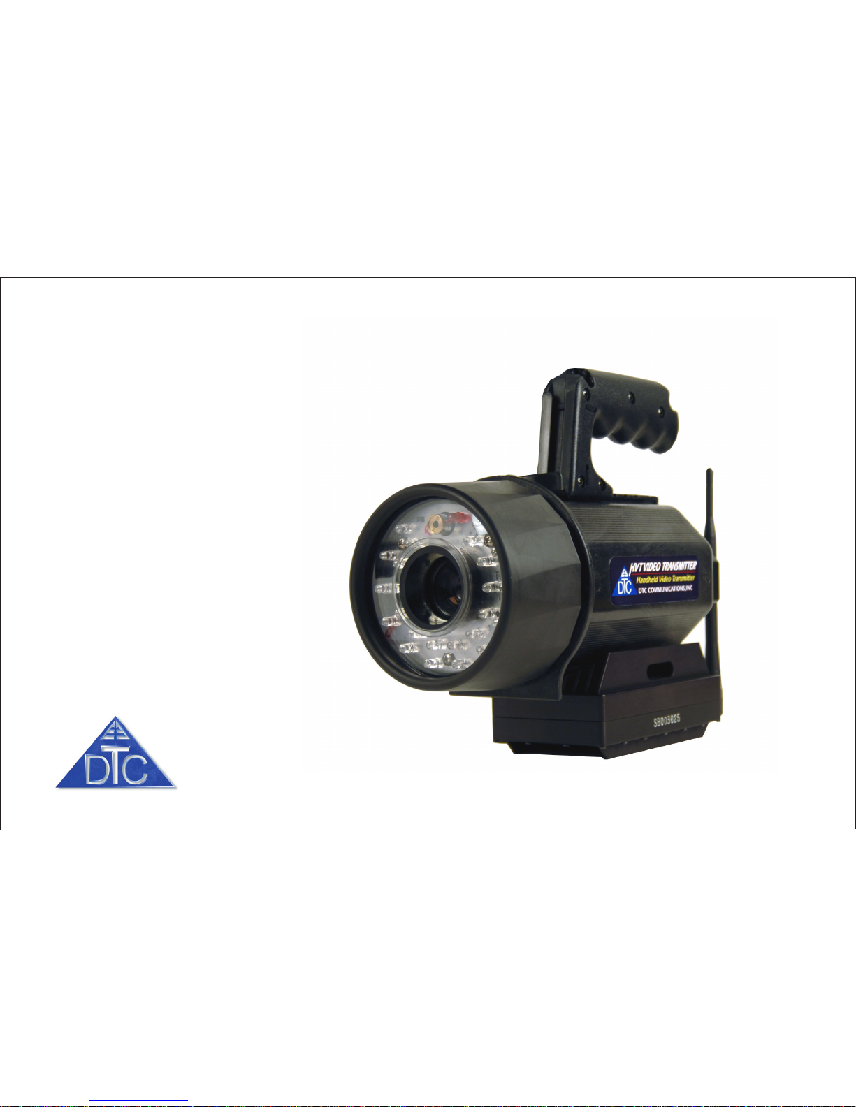
Portable Day/Night Camera and
Digital COFDM Transmitter
DTC COMMUNICATIONS, INCORPORATED
Handheld Video Transmitter
Page 2

DTC COMMUNICATIONS, INC.
2
warranty
DTC warrants its manufactured components
against defects in material and workmanship
for a period of two (2) years, commencing on
the date of original purchase.
Products manufactured by others that are
approved for use with DTC equipment are
warranted for the manufacturer’s warranty
period, commencing from the date of shipment
from DTC.
PN OP1920330 REV 2
copyright notice
Copyright © 2005, 2006
DTC Communications, Inc. All rights
reserved. No part of this document may be
reproduced, transmitted, transcribed, stored
in a retrieval system or translated into any
language or computer language, in any form
or by any means, including but not limited to
electronic, magnetic, mechanical, optical,
chemical, manual or otherwise, without the
prior written permission of DTC
Communications, Inc.
disclaimer
The information in the document is subject to
change without notice. DTC makes no
representations or warranties with respect to
the contents hereof, and specifically disclaims
any implied warranties of merchantability or
fitness for a particular purpose. DTC reserves
the right to revise this publication and to
make changes from time to time in the
content hereof without obligation of DTC to
notify any person of such revision or changes.
trademarks
Trademarks of DTC Communications, Inc.
include:
• DTC
• MiniPIX
TM
• SplitPIX
TM
• DynaView
TM
• Palladium
TM
• ArmorNet
TM
Other product names used in this manual are
the properties of their respective owners.
how to contact DTC
For operator and troubleshooting information,
customers are encouraged to refer to the
details in this manual. For additional
clarification or instruction, or to order parts,
contact DTC.
Customer Service is available Monday through
Friday between the hours of 9:00 AM and
5:00 PM EST at:
Tel: 603-880-4411
Fax: 603-880-6965
Website: www.dtccom.com
Email: [email protected]
486 Amherst Street
Nashua, New Hampshire 03063
Page 3
DTC COMMUNICATIONS, INC.
3
NOTE: Describes special issues you should
be aware of while using a particular function.
WARNING: Calls out situations in which
equipment could be damaged or a process
could be incorrectly implemented, but in
which operator safety is not a factor.
TIP: Describes application hints.
RF EXPOSURE STATEMENT
A separation distance of at least 20 cm must be
maintained between the antenna and the body of
the user or nearby persons.
NOTE: This device is for occupational use
only. Occupational users are those persons
who are exposed as a consequence of their
employment, provided these persons are fully
aware of and exercise control over their
exposure.
manual conventions
Quick Start ............................................................................ 4-5
Complete These Steps................................................................ 4
Battery Charging ......................................................................... 5
Introduction ............................................................................... 6
Operation ............................................................................... 7
Using your HVT........................................................................... 7
Changing your Transmitter Configuration .................................... 7
Components ........................................................................... 8-9
Programming...................................................................... 10-15
System PC Controller Application Software.............................. 10
Transmitter Control Application ................................................. 11
Specifications..................................................................... 16-17
Accessories ............................................................................. 18
Contact Us ............................................................................. 19
TABLE OF CONTENTS
Page 4
DTC COMMUNICATIONS, INC.
4
Complete these steps:
QUICK START
Accessories
• Shipping Case w/Quick Guide
• Extra Battery Pack
• Battery Chargers (2):
• Connect to Battery (External)
• Connect to Flashlight (Internal)
• External DC Power Conditioner
w/Cigarette Adapter
• Programming Cable
• Programming CD
• User Manual
• Lens Cleaning Wipes
• Lens Cleaning Cloth
• Silicon O-Ring Lubrication
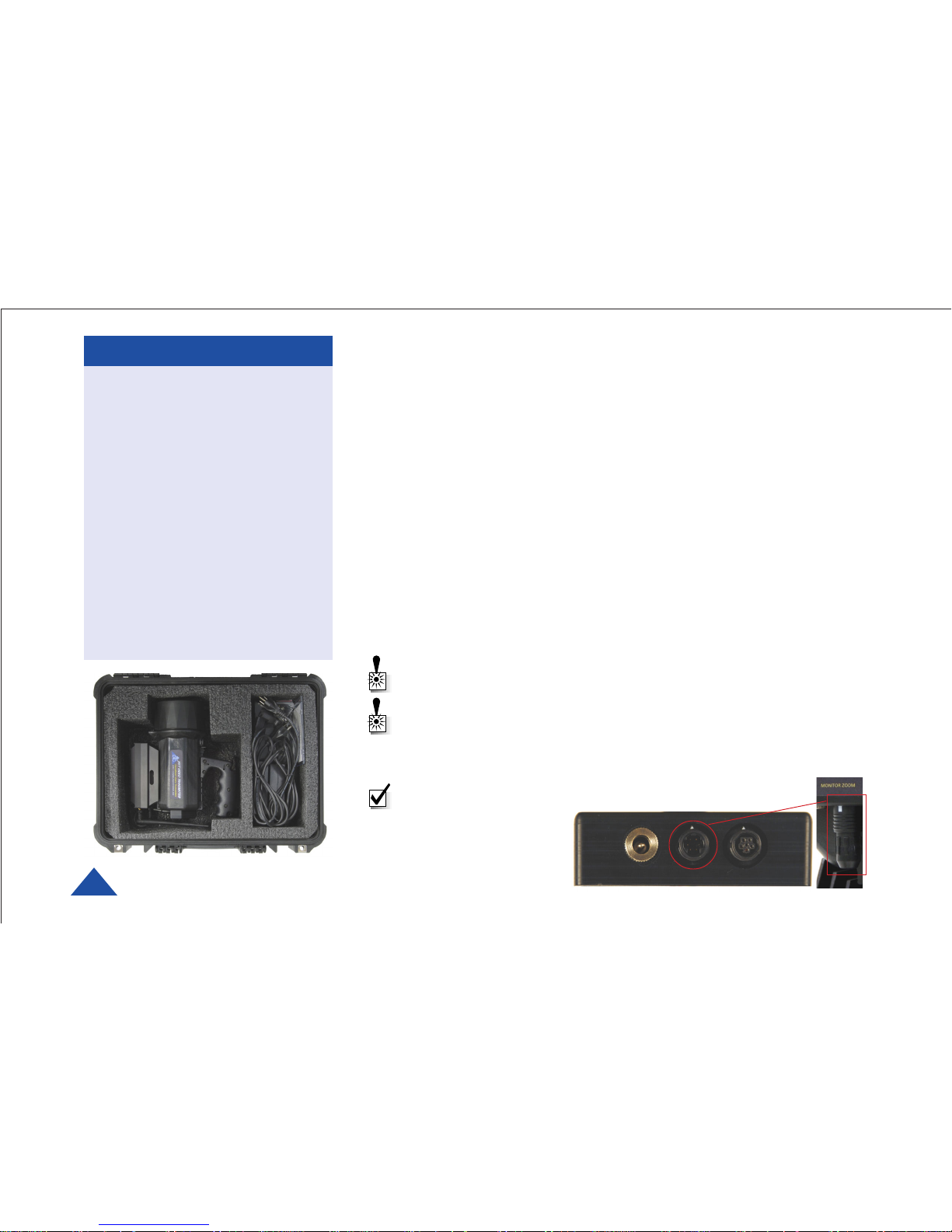
HVT Shipping Case
1. Make sure the antenna is connected to the transmitter.
2. Be sure to start each mission with a fully-charged battery pack.
See Charging the HVT battery pack (page 5). The RED LED blinks
when the battery is low. If using alternative power source, connect
through Ext. DC Power Source module supplied.
3. Select the Channel on the transmitter that matches the frequency and
settings of your receiver or repeater receive Channel.
For programming instructions, see Programming on pages 10 to 15.
4. Unlock the Main Power Switch. Set the Main Power switch to LEFT for
illumination, or RIGHT for camera TX only.
5. To operate the spotting laser, press the Laser ON/OFF Button. An LED
in the button indicates ON/OFF State. The laser spots for
approximately 30 feet, placing a dot in the center of the image. The laser
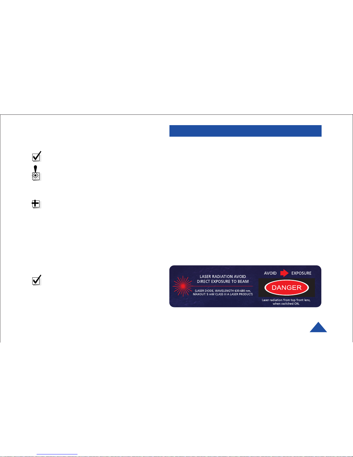
produces a beam strength of less than 5 mW and is blink safe.
WARNING: Do not apply power to the transmitter unless an antenna
or non-radiating load is connected to the Antenna SMA connector.
WARNING: Do NOT connect external DC power sources directly to
the HVT. Connect all external DC sources through the supplied
Ext. DC Power Source module. (Examples: car battery, customersupplied battery, etc.)
NOTE: Ensure the Zoom Retainer is plugged-in to the
Monitor Zoom connector
to ensure a 1:1 zoom
setting. (See Page 7.)
Otherwise, the zoom
setting is not controled.
Page 5
DTC COMMUNICATIONS, INC.
5
QUICK START
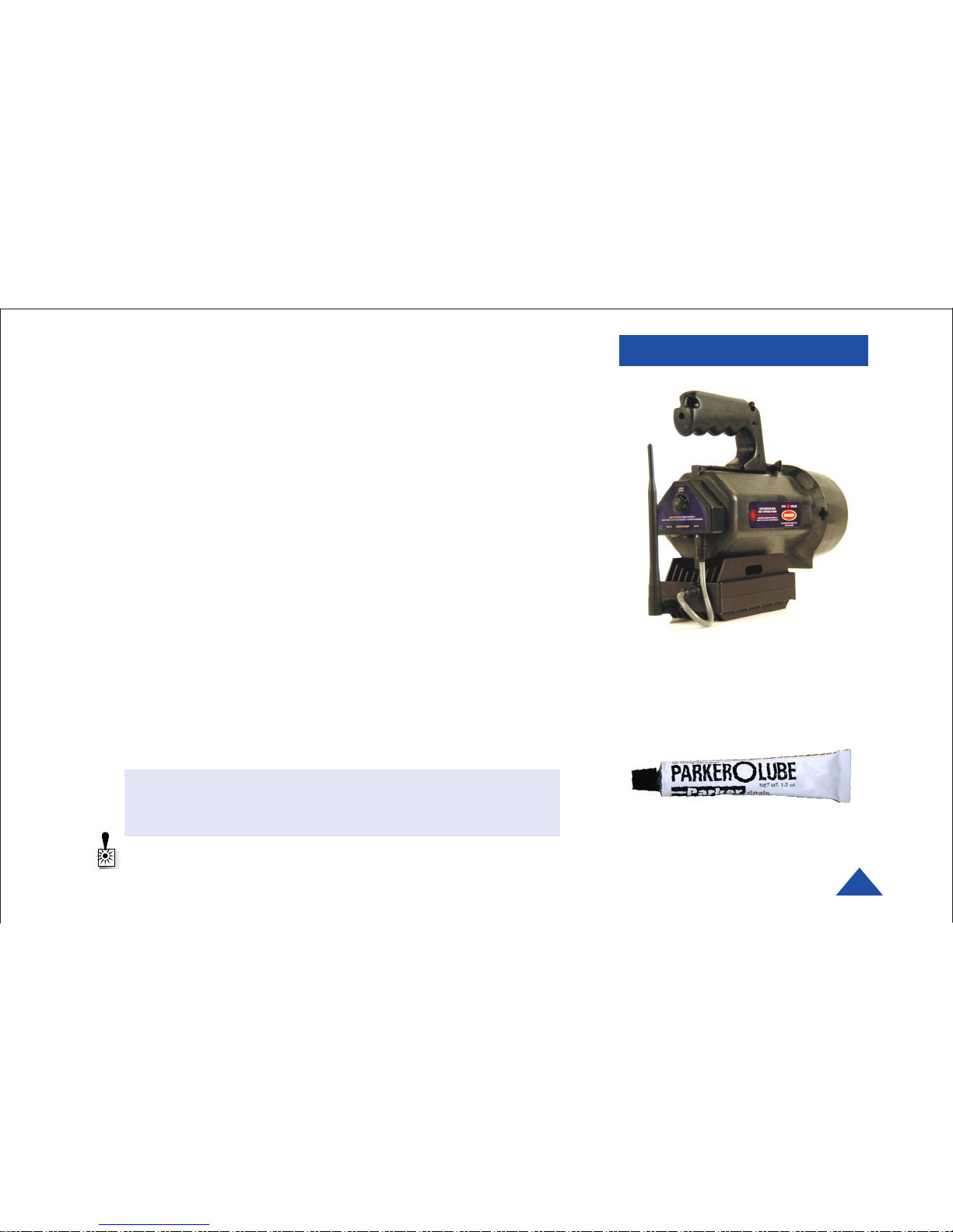
Handheld Video T r ansmitter,
Rear View (Antenna position shown for
reference only. Adjust antenna position
for best performance.)
O-Ring Lubricant
Charging the HVT battery pack
(external method):
A. Make sure the Main Power Switch is in the center position.
B. Loosen and remove the front bezel.
C. Grasp black plastic ring and carefully pull out assembly.
D. Unplug 13-pin Hirose connector and fully remove assembly.
E. Unplug DC power connector, loosen Velcro straps and replace battery
pack with a fully charged spare (at least 3 hours charging time).
Charging the HVT battery pack
(internal method):
F. Turn the HVT Main Power Switch to OFF (center).
G. Attach the Battery Charging cable to the Ext. Power Input Connector.
H. Connect AC Charger unit to proper power source.
(The battery will charge at a slower rate when the HVT is powered from the Ext. DC Power Conditioner.)
J. Charge the HVT battery pack for at least three hours.
Reassembly Tips
• Align external and internal switches to center position to prevent
damage to switch.
• Keep threads, O-ring groove, and inside lip of bezel lubricated with
Silicone Grease.
• Screw together firmly. Periodically check O-ring for damage.
BATTERY CHARGER:
ORANGE = CHARGING,
FLASHING GREEN or ORANGE = CHARGING TOP OFF,
GREEN = CHARGED
WARNING: Make sure the Main Power Switch is in the center
position during disassembly and reassembly or damage to the
switch may occur.
Page 6

DTC COMMUNICATIONS, INC.
6
INTRODUCTION
The Handheld Video Transmitter
The Handheld Video Transmitter is the latest innovation in tactical video
reconnaissance and digital video transmission from DTC. First responders
will find the HVT valuable for search and rescue, assessing threats,
physical security, and disaster sites. The HVT is an essential tool for
government, military, and law enforcement teams.
Weighing only 5.5 pounds and completely portable, the HVT uses a
Palladium digital transmitter and fits in a durable 9.8 by 9.0 by 4.8 inch
package. Rechargeable Lithium batteries provide a nominal runtime of
three hours with all features ON. Even longer runtimes are achieved with
the illuminator LED’s and laser turned OFF. The LED’s are ultra-bright
and efficient, providing sufficient illumination for excellent video in near
total darkness.
A red spotting laser provides a safe method of effectively pointing the
camera without the need for a monitor. The HVT was designed to go
virtually anyplace and to work well in virtually any environment from
sunlight to darkness. The HVT is the essential tool for tactical video
collection and transmission. A miniature color video camera is fitted in the
center of the HVT, with dual banks of illuminator LED’s in concentric
circles around the camera.
Two types of LED’s are used with illumination beam-widths of 20 degrees
and 45 degrees. This combination provides both a spot light and an
effective flood light, with a combined output designed to recognize a person
in a dark room at a 12-foot distance.
The HVT can be ordered to provide either NTSC or PAL video.
HVT, Front View
Page 7
DTC COMMUNICATIONS, INC.
7
OPERATION
Using your HVT Transmitter
Follow the instructions given in the Quick Start section on pages 4-5.
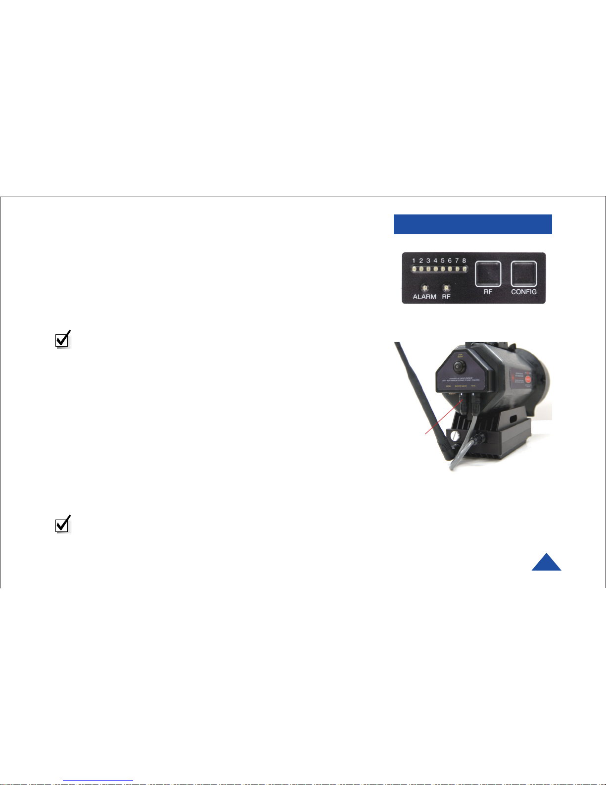
When power is first applied to the HVT, the unit reverts to the last used
channel and RF (ON/OFF) state. One of the green channel LEDs will turn
ON indicating the active channel. The Alarm LED may be ON, which
indicates that there is no active video input.
NOTE: Since the Palladium transmitter always returns to the last
configuration on power-up, the unit should always be deployed with
the RF switch ON. Therefore, once deployed, control of the unit must
be restricted to applying and removing power via the HVT Main
Power Switch.
Changing your Transmitter Configuration
The Palladium Transmitter can store up to 8 different configurations,
which can be selected on the front panel. Each of these configurations can
be programmed into the Transmitter with the supplied DTC Programming
Software and a Windows PC. Refer to the Programming section on page 10
for more information.
To cycle through your preconfigured channels press the CONFIG button
once to advance to the next setting. By default, the Palladium will turn
OFF the transmitted signal while you are changing channels. This is to
prevent accidental interference. Push the RF button after channel selection
to resume RF transmission of your video image.
NOTE: DO NOT HOLD THE RF BUTTON DOWN FOR MORE THAN
ONE SECOND, or the unit will go into sleep mode. In sleep mode, the
unit is non-functional. If necessary, recover from sleep mode by
pressing and holding the RF button for more than two seconds.
HVT Transmitter Control Panel,
Located on Bottom
Zoom
Retainer
Plug-in the Zoom Retainer to ensure a
1:1 Zoom setting. If not plugged-in, the
zoom may change state randomly.
Page 8
DTC COMMUNICATIONS, INC.
8
COMPONENTS
WARNING: You can damage
internal compoinents if you
do not take precautions.
Electrostatic Discharge (ESD),
caused by static electricity,
can damage sensitive
electronic parts. You can
reduce the chances of ESD
damage by using proper
grounding and handling
techniques, especially when
accessing battery packs.
Handle with care and do not
expose internal components
to dirt, water, or other foreign
substances.
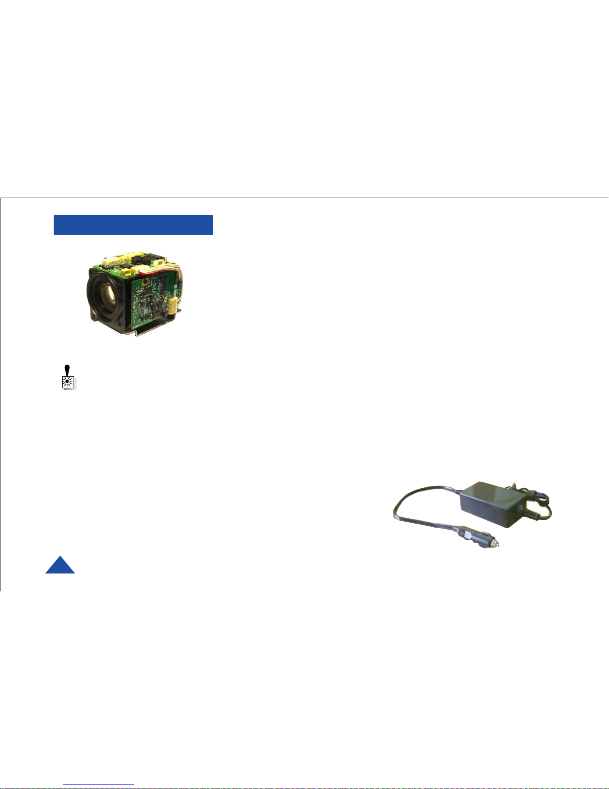
Camera Module
Auto Iris
The Auto Iris camera feature allows the device to automatically adjust for
varying lighting conditions. This feature emulates the human iris, which
opens in dark conditions to let in more light and closes down in bright
light to prevent overexposure.
The HVT camera will accomodate a wide range of ambient light from bright
sunlight to near total darkness. You may notice a slight delay for the
camera to adjust when moving between these conditions.
Auto Nightshot
When ambient light is too dim for color reproduction, the HVT camera
automatically switches to black and white mode. Black and white mode
requires less light than color. This feature emulates the human eye, which
sees in black and white in darkened conditions. You may notice a slight
delay for the camera to adjust when moving between these conditions.
Auto Focus
The HVT camera can focus on objects from a few inches away to infinity.
The Auto Focus feature constantly monitors distance and adjusts the focus
to optimize the image. You may notice a slight delay for the camera to
adjust when moving between these conditions.
Camera Mount
The HVT is equipped with a standard 1/4 - 20 camera mount for
convenient attachment to a tripod, monopod, or other support.
Ext. DC Power Source
Use only the Ext. DC Power
Conditioner provided. This is a
regulated, filtered DC to DC converter
suitable for automotive power connection. It
has a cigarette-lighter adapter. Other DC power
sources can be connected to the Conditioner through
the Ext. DC Power Input Jack: Input voltage range: 10.0 to 15.0 VDC.,
Output voltage: 12 VDC @ 75 Watts.
Page 9
DTC COMMUNICATIONS, INC.
9
COMPONENTS
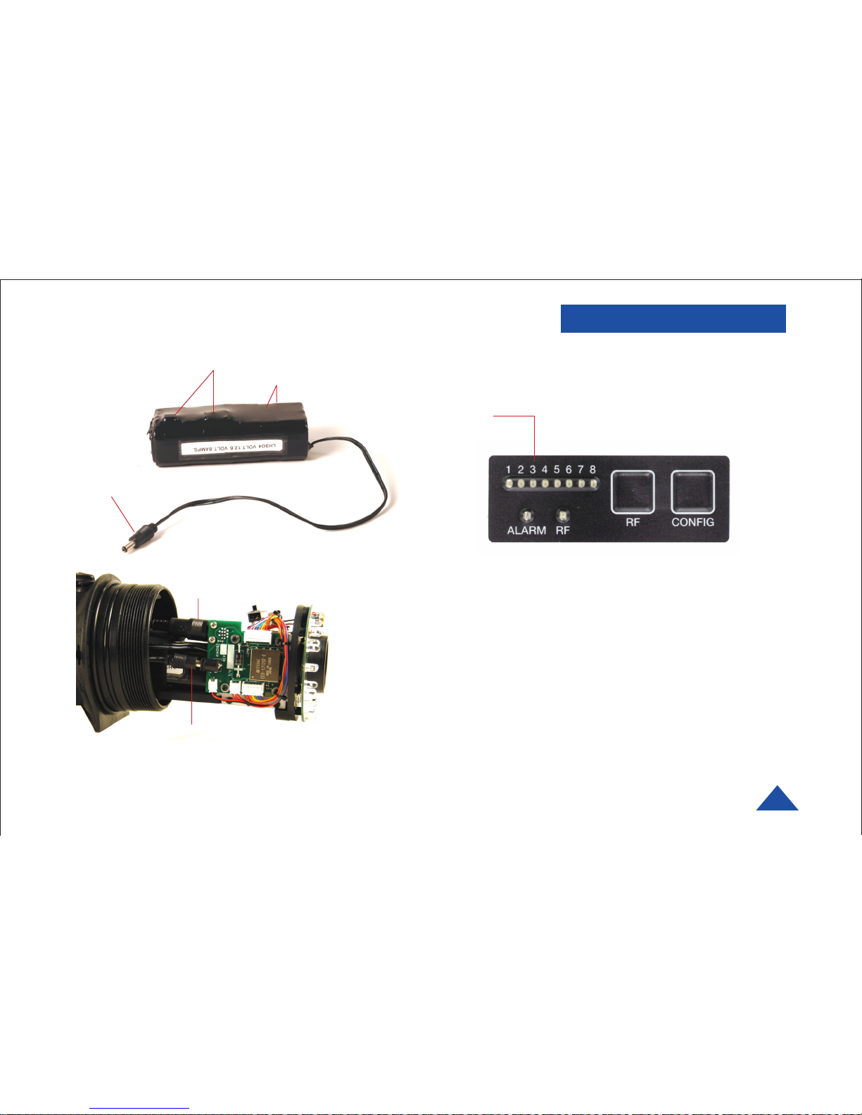
ALARM LED This red LED indicates a valid video signal
is not present. In addition, if no other LED is ON, the
ALARM LED indicates battery is less than 10 Volts.
RF LED This green LED indicates that the RF
output is ON.
RF Button This membrane switch toggles ON/OFF the
RF output. Normally this should be left ON.
CONFIG Button This membrane switch cycles through
the eight channels.
Channel LEDs These green LEDs, numbered 1 through
8, indicate the channel number currently selected.
Each channel represents a set of preconfigured
settings.
Do not cinch the Velcro® battery strap here or you
could damage the PC board inside.
Cinch the battery strap here.
Power Connector
Power Connector
Hirose Connector
Battery Pack
You must disconnect the Hirose Connector and the
Power Connector in order to access the Battery Pack.
HVT, Partially Disassembled View
HVT Transmitter Control Panel,
Located on Bottom
Page 10
DTC COMMUNICATIONS, INC.
10
PROGRAMMING
System PC Controller Application Software
Advanced control of the system is available by using the PC control
application software. Typically users may want to customize the default
configurations to control settings such as frequency, scrambling keys,
modulation parameters, and video resolution.
The transmitter is controlled by the application DTC_tx_ctrl.exe
available on the CD delivered with the product.
A PC is required with an available RS232 Serial COM port to control the
transmitter.
Installation of the control program is as simple as copying the file from the
CD to a suitable location on the PC. No install shield routine is launched.
Note that the application generates its own log and initialization files, so it
is best to create a dedicated directory for these applications, perhaps with
links to the applications from the desktop of the PC.
Getting Started
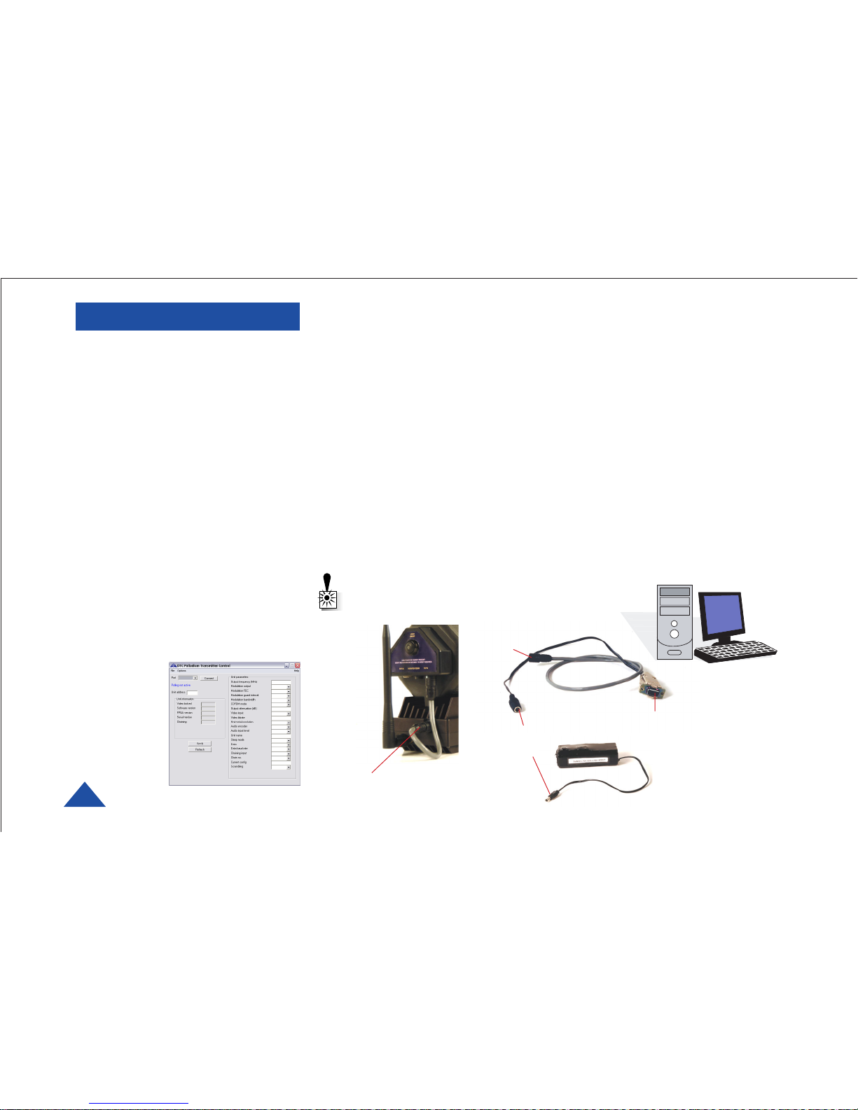
•Use the supplied programming
cable to connect the chosen COM
port of your PC to the transmitter
to be configured.
•Launch the application by double
clicking or using the Run...
command.
•Connection with a transmitter
should be automatic, but the user
can force selection of the correct
COM port using the drop down,
followed by the Connect button.
•Select the channel to be configured
from the unit’s front panel CONFIG
button
•Click Refresh in the application to
display the current configuration.
•Update the
current
settings in
the application, then
click Apply
to save to
memory
Transmitter
Multi-I/O
Connector
To PC Serial
RS-232 Port
To Transmitter
Multi-I/O
Connector
To External
HVT Battery
Pack Conn.
WARNING: Connect an antenna to the TX
before connecting power.
Page 11
DTC COMMUNICATIONS, INC.
11
PROGRAMMING
Transmitter Control Application
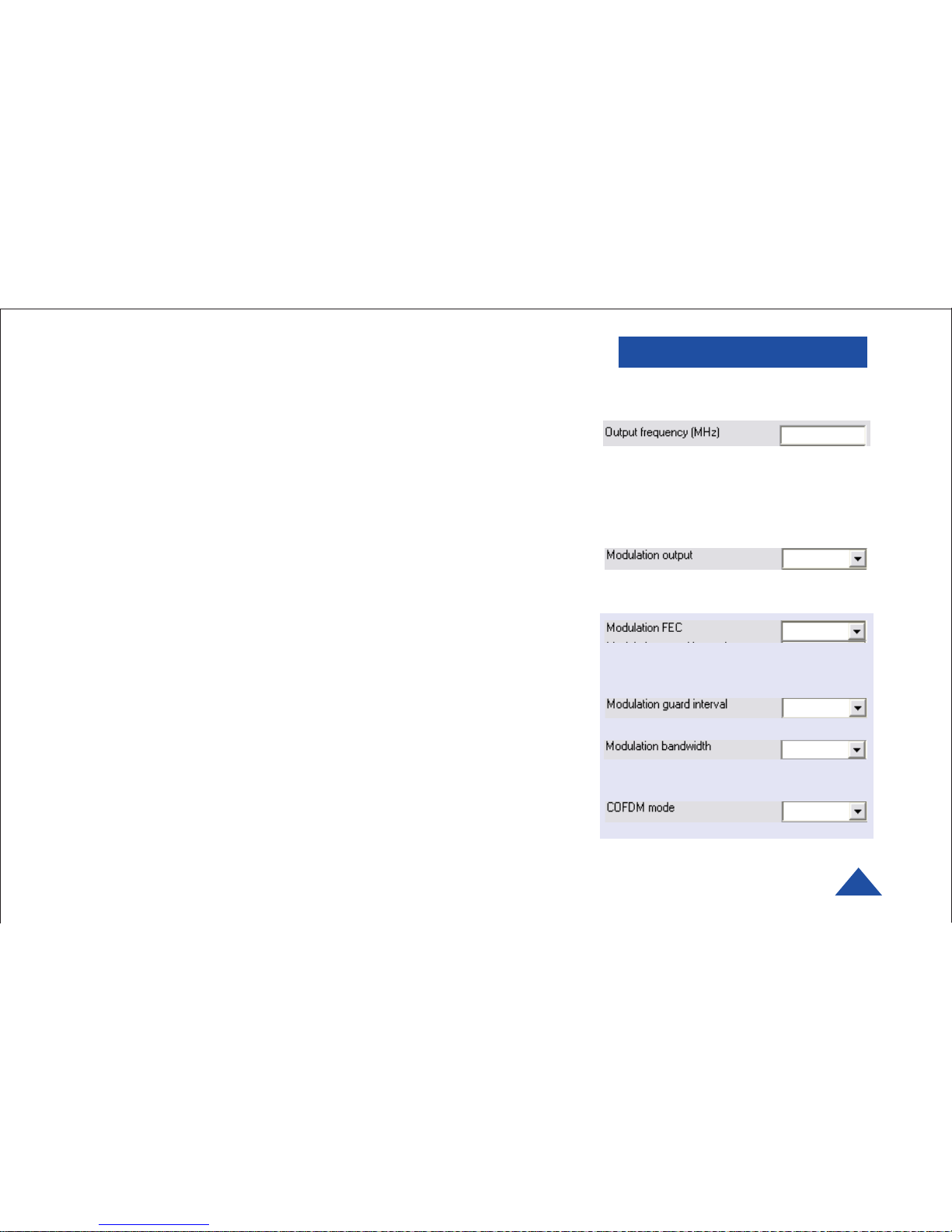
Output Frequency (MHz)
The transmit frequency can be changed by entering the new desired
frequency in this field. Values outside the range supported by a particular
transmitter type will be rounded to the highest or lowest supported
frequency as appropriate. The transmit frequency may be entered in
1MHz steps.
Modulation Output (same as RF button functionality)
This control is used to turn on and off the RF output. After a configuration
change, the output always reverts to OFF. It must be ON for operation.
Either press RF button on front panel or select ON and Apply
from application.
Modulation FEC*
The default FEC is 2/3, however improved range operation can be achieved
by selecting FEC 1/3. FEC 1/3 will improve signal range by 3dB. However
FEC 1/3 reduces link capacity to 1.2Mb/s. FEC 2/3 is recommended.
Modulation Guard Interval
The Guard Interval is fixed at 1/16 in current firmware releases.
Modulation Bandwidth
For the Palladium transmitter products, the modulation bandwidth is fixed
at 2.5MHz in current firmware release.
COFDM Mode
The COFDM mode can be changed between QPSK and 16QAM. QPSK is
the default mode and will give the strongest most rugged RF link
performance. Selecting 16QAM reduces the link performance by 5dB but
doubles the link data throughput.
Default values are shown in red.
OFF
2/3
1/16
2.5 MHz
QPSK
(your frequency)
*Advanced options are shown in blue. These
options are for trained and experienced technicians only.
Page 12
DTC COMMUNICATIONS, INC.
12
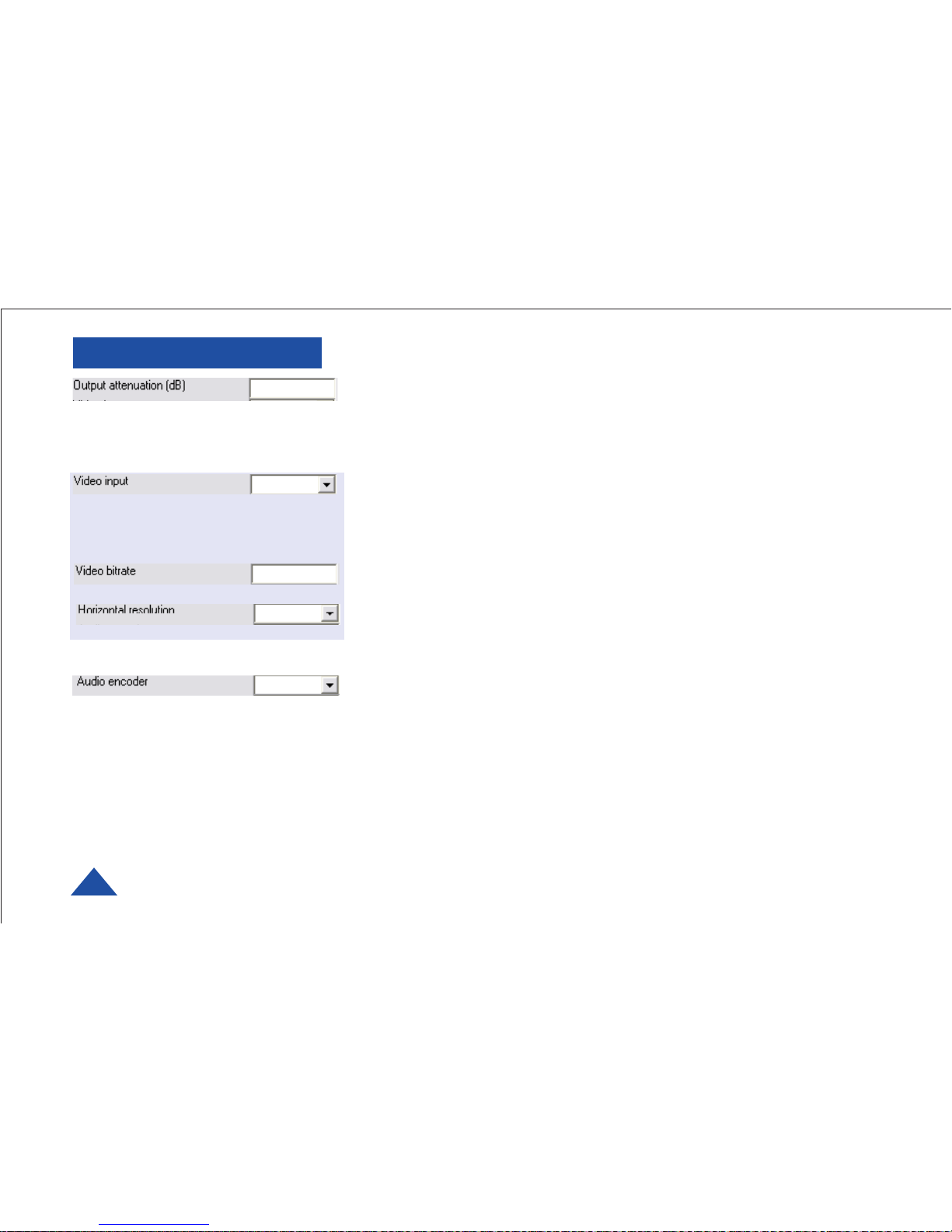
Output Attenuation
This control can be used to make minor adjustments to the output power
level, but in normal operation should not be changed from factory settings.
(0 attenuation = full output power, greater than 0 attenuation = reduced
power in 1 dB steps.)
Video Input
This control is used to select the composite video input standard. Options
are PAL, and NTSC both with and without 7.5 IRE black level pedestal.
PAL/NTSC should be selected according to the camera format. NO pedestal
is correct for most applications.
Video Bitrate (status only)
Displays data capacity for video channel.
Horizontal resolution
The video coding resolution can be selected from 704, 528, 480 and 352
pixels. For optimum performance, choose a resolution one step better than
your camera’s resolution.
Audio Encoder
Not available in this device.
PROGRAMMING
(As Desired)
NTSC
1.1
528
OFF
Default values are shown in red.
Advanced options are shown in blue. These
options are for trained and experienced technicians only.
Page 13
DTC COMMUNICATIONS, INC.
13
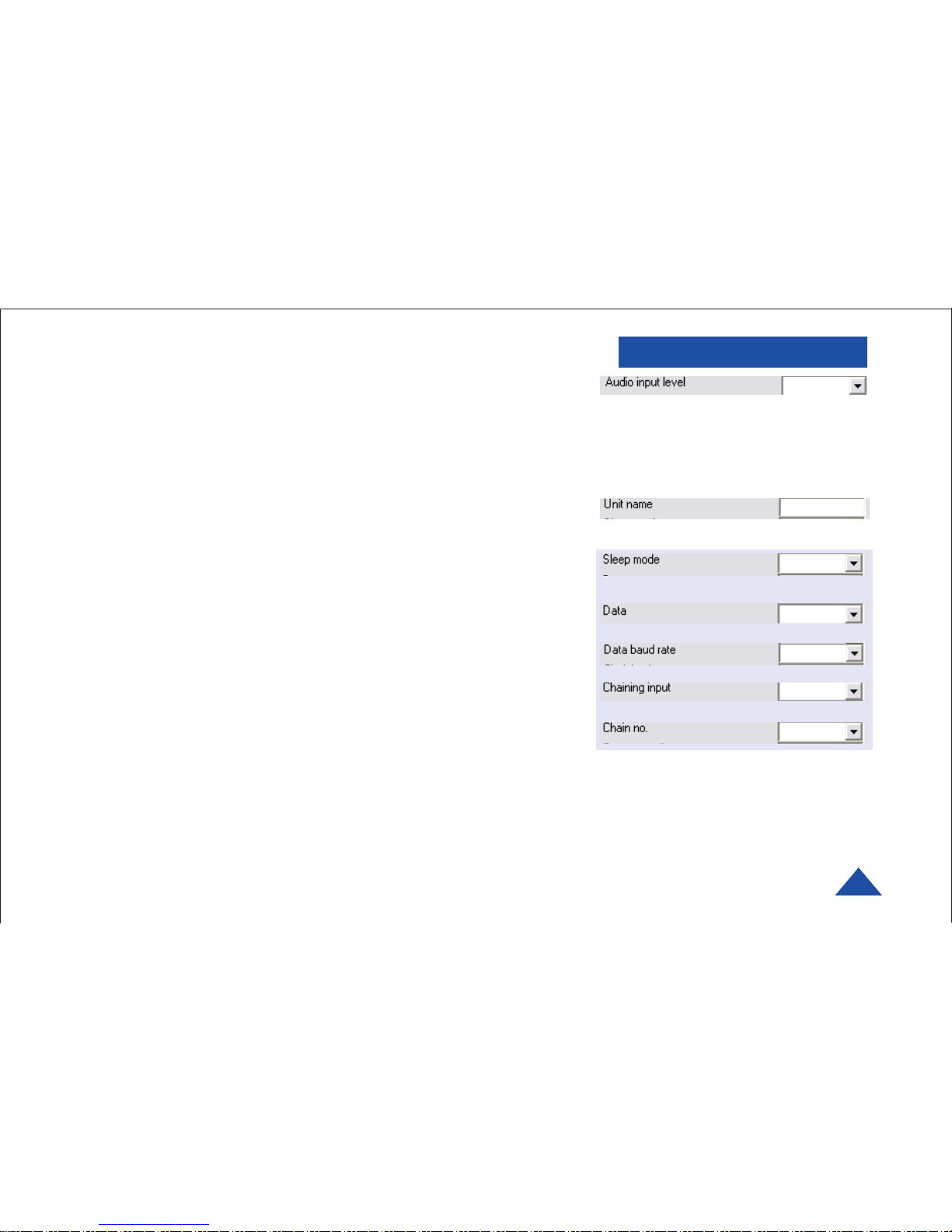
Audio Input Level
Not applicable to this device.
Unit Name
Enter up to 16 characters to identify unit as desired.
Sleep Mode
This control allows the unit to be forced into a Sleep Mode where main
functions are disabled, and the power consumption is significantly reduced.
Data
Future use.
Data Baud Rate
Future use.
Chaining Input
Future use.
Chain Number
Future use.
PROGRAMMING
24 dB
(As Desired)
NO
OFF
1200
OFF
0
Default values are shown in red.
Advanced options are shown in b lue. These
options are for trained and experienced technicians only.
Page 14
DTC COMMUNICATIONS, INC.
14
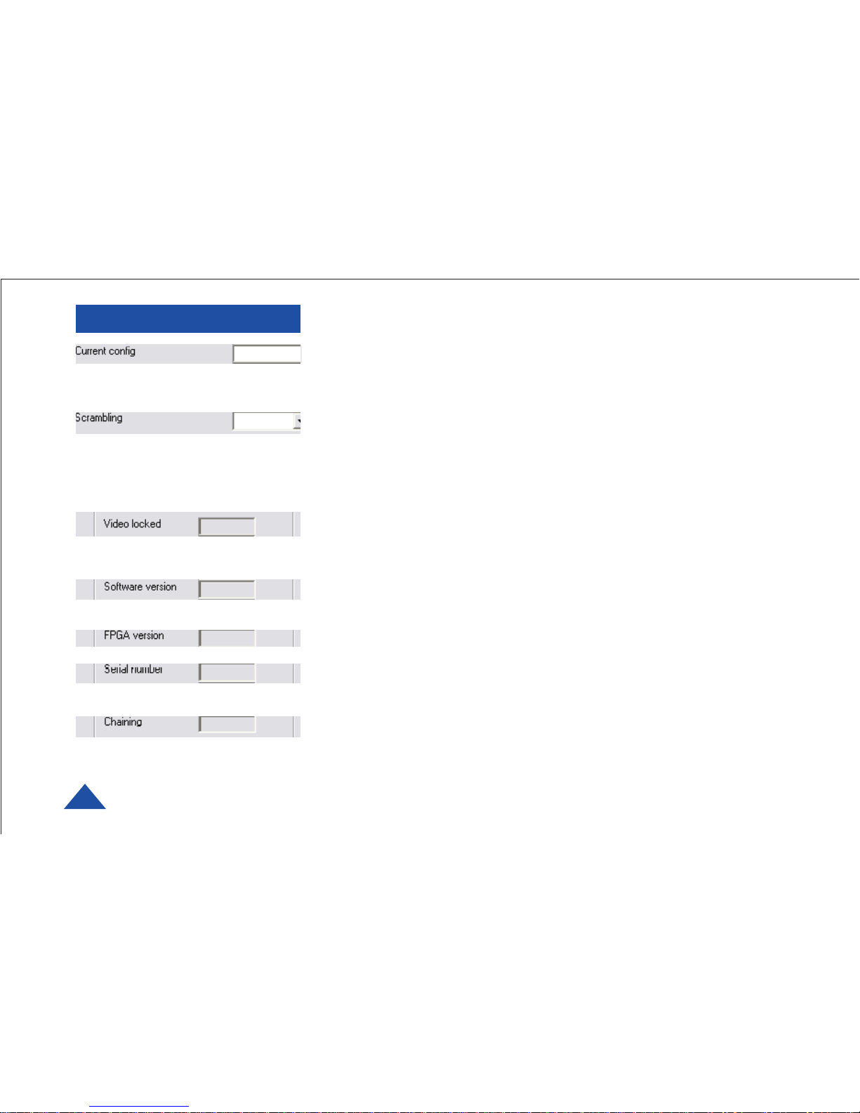
Current Config (same as display panel)
This field reports the last loaded configuration number (1-8). Note that for
the Palladium transmitter, changes applied after the configuration has
been loaded are saved immediately into the current configuration. To select
another configuration, enter number (1-8) then click Apply.
Scrambling
Scrambling is enabled at the transmitter by selecting AES in the
scrambling field. At this point the user will need to ensure that the correct
key is in use and this is done by using Options/Write AES key. The key is
128 bits and is entered as 32 ASCII hexadecimal characters (0-9 and A-F).
(256 bit is optional.)
Video Locked (Status Only)
This status information indicates whether the transmitter is successfully
locked to the incoming composite video signal. Unlocked status may
indicate cabling faults, or poor quality incoming video feeds to the unit.
Software Version (Status Only)
This status information describes the version of the software running the
transmitter product.
FPGA Version (Status Only)
Engineering use only.
Serial Number (Status Only)
This status information is the electronic serial number of the transmitter
PCB. This number can be used for upgrades or support.
Chaining (Status Only)
Future use.
PROGRAMMING
(Ch. No.)
OFF
Default values are shown in red.
Page 15

DTC COMMUNICATIONS, INC.
15
Options
Timeouts – password protected access to change timeouts used during
the serial communications between the unit and the controller.
Engineering – password protected access to further diagnostic and
calibration features.
Write License Code – open a further password protected box for entering
license codes for future upgrade.
Change RS232 address – (future use).
Write AES Key – opens a dialog box for entering a customer-selected
scrambling key. A key is a combination of 32 hexadecimal characters (64
for optional 256-bit encryption). Hexadecimal characters are 0, 1, 2, 3, 4,
5, 6, 7, 8, 9, A, B, C, D, E, and F. The receiver and transmitter must have
identical AES keys.
Restore Defaults – restores factory default settings in the transmitter.
Polling Enabled – selecting this option makes the control application
automatically refresh the data presented to the user every few seconds.
File
Load Config – used for loading configuration data to text file.
Save Config - used for saving configuration data to text file.
Change Logfile – opens a standard Windows file save dialog box which
allows the user to change the path and name of the log file generated by
the application.
Exit – exits the control application.
PROGRAMMING
Advanced options are shown in b lue. These
options are for trained and experienced technicians only.
Page 16

DTC COMMUNICATIONS, INC.
16
Physical
Unit Dimensions (approx.) 9.8” (24.892cm) L x 9.0 (22.86cm) ”H x
4.8” (24.892cm) D
Weight 5.5 lbs. (2.5 kg)
5:1 Water: Chlorine bleach solution Protected from immersion at 1 meter deep for
30 minutes (IP67)
Tripod Mount 1/4 - 20 threaded hole at bottom of housing
Environmental
Operational Temp 0o F (24.892oC) to 120o F (48.99oC)
Power
Input Voltage 10 to 15 VDC through Ext. DC Power
Conditioner 12 VDC @ 60 Watts max.
Battery Voltage 12 V @ 20 W typical
Low Battery Red LED is ON when battery approaches end-
of-life (approx. 10.5 VDC).
Battery Life 3 hours nominal on full charge w/illuminator at
50% duty cycle.
Chargers (1) Internal, (1) External
100 to 240 VAC, 50/60 Hz Input
Control
PC Control Interface RS-232.
Memory 8 user-programmable configurations
Video Encoding
Compression Standard MPEG-2 with non-DVB modes
Chrominance Profile 4:2:0
Line Standard PAL 625 or NTSC 525
Horizontal Resolution 704, 528, 480, 352 pixels (528 as standard)
Vertical Resolution 576 (625 lines) or 480 (525 lines)
Video Bitrates 1Mbps to 10 Mbps
System Latency End to end delay of approx. 54 milliseconds
SPECIFICATIONS
Page 17

DTC COMMUNICATIONS, INC.
17
SPECIFICATIONS
Scrambling
Scrambling type Fixed key scrambling system
Algorithms offered include AES.
(AES 256 Optional)
COFDM RF output
Output Frequency Band Dependent
Occupied Bandwidth 2.44 MHz
Power 250 mW
Connector SMA
COFDM Standard Proprietary, 2.5 MHz channel bandwidth.
Video Output
External Video Output Optional Remote Video Out and Zoom Control
Camera
Image Sensor 1/4-inch CCD
Resolution 500 TV Lines
Auto Iris AES
Lens F1.8 to 2.9, f= 4.2 to 42 mm
Focus Automatic
Antenna
Omnidirectional, articulating base Rubber duck style dipole SMA 50 Ohms
Laser Pointer
Spotting laser 5 mW (blink safe) red, button switch actuated
Illuminator
Ultrabright LED array 141 total candlepower
Page 18

Accessories DTC Part Number
• Shipping Case
w/Quick Guide QG1920330
• Extra Battery Pack 8030091
• Battery Chargers (2):
• Connect to Battery (External) 4640129
• Connect to Flashlight (Internal) 8340090
• External DC Power Conditioner w/
Cigarette Adapter 8340093
• Programming Cable 4640168
• Programming CD 8002027
• User Manual OP1920330
• Lens Cleaning Wipes 8530102
• Lens Cleaning Cloth 8530101
• Silicon O-Ring Lubrication 8500173
ACCESSORIES
Page 19

CONTACT US
Contact Information
Nashua Main Office Numbers
486 Amherst Street
Nashua, New Hampshire 03063 USA
(T) 603 880-4411
(F) 603 880-6965
Toll Free in the USA
1-800 233-8639
REGIONAL SALES MANAGERS
Howard Rich
toll free (888) 819-8570
voice (860) 626-8570
fax (860) 626-8571
NY, MA, CT, RI, PA, NJ, MD, DE, WV, DC
[email protected]
Gary Nichols
toll free (866) 794-2823
voice (765) 473-8917
fax (765) 473-8920
MN, WI, MI, IA, MO, IL, IN, OH, KY, NE
[email protected]
Joe Parkinson
toll free (800) 952-4914
voice (928) 443-9399
fax (928) 443-9302
CA, AZ, NV, HI, UT, AK
[email protected]
Inside Sales
State & Local Law Enforcement
603 546-2217
Federal Law Enforcement
603 546-2169
Military
603 546-2121
International
603 546-2217
A complete listing of Contact Individuals
can be located on our website at:
www.dtccom.com
Christine Guzman
toll free (800) 233-8639
voice (603) 546-2217
fax (603) 880-6965
NH, VT, ME
[email protected]
Ed Bryant
toll free (800) 396-0295
voice (903) 725-7229
fax (903) 725-6952
cell (903) 399-5496
CO, KS, OK, AR, NM, TX, LA
[email protected]
Greg Langley
voice (702) 236-0021
fax (702) 293-6448
WA, OR, ID, MT, ND, WY, SD
[email protected]
Frank Prioli
toll free (800) 246-2610
voice (727) 392-4761
fax (727) 320-0509
FL, GA, AL, MS, TN, NC, SC, VA
[email protected]
Page 20

486 Amherst Street • Nashua, New Hampshire 03063 • 603-880-4411
www.dtccom.com
 Loading...