

Page 1
DSS NETWORKS
GigMAC PMC/PCI Controllers
Board and Driver Users Manual
(Includes models 5161, 5162, 5164, 5261, 5262, 6161, 6167, 6162 and 7160)
Document Version 2.0, P/N 131900
June 2004
Page 2

GigMAC PMC and PCI Board and Driver Users Manual
1. INTRODUCTION..................................................................................................................... 3
1.1 SEE ALSO............................................................................................................................. 3
1.2 COMPATIBILITY................................................................................................................... 4
2. MODEL NUMBERS................................................................................................................. 4
3. FEATURES ............................................................................................................................. 5
4. OEM DEVELOPER KIT CONTENTS...................................................................................... 5
5. SYSTEM REQUIREMENTS ................................................................................................... 6
6. BOARD AND CONNECTOR INFORMATION ........................................................................ 7
6.1 BOARD PHOTOS ................................................................................................................. 7
6.2 BOARD LED INDICATORS .................................................................................................. 8
6.3 PMC CONNECTOR PIN/SIGNAL DEFINITIONS............................................................... 11
7. POWER CONSUMPTION SPECS ....................................................................................... 14
8. HARDWARE INSTALLATION............................................................................................... 14
8.1 INSTALLATION IN PC COMPUTER .................................................................................. 15
8.2 EMBEDDED OR COMPACT PCI INSTALLATION............................................................. 15
9. COPPER CABLING AND CONNECTOR INFO.................................................................... 16
9.1. FIBER CABLE SPECIFICATIONS..................................................................................... 16
9.2 COPPER RJ-45 CONNECTOR AND CABLE..................................................................... 17
10. SOFTWARE DRIVER INSTALLATION............................................................................... 18
10.1 VXWORKS DRIVER INSTALLATION AND USAGE ........................................................ 18
10.2 LINUX DRIVER INSTALLATION AND USAGE ................................................................ 18
10.3 DPM DRIVER MANAGEMENT API.................................................................................. 26
10.4 WINDOWS DRIVER INSTALLATION............................................................................... 28
11. TESTING AND VERIFICATION.......................................................................................... 29
12. SPECIFICATIONS .............................................................................................................. 30
13. WARRANTEE AND SUPPORT INFO................................................................................. 33
DSS NETWORKS, INC.
Version: 2.0 Page: 2
Page 3

GigMAC PMC and PCI Board and Driver Users Manual
1. INTRODUCTION
The GigMAC family of network controllers are a high-performance, cost-effective
solution for adding Gigabit Ethernet connectivity to any embedded or real-time
Network Appliance, Switch, Router, Server or other access device equipped with
a PCI or PMC Mezzanine slot and is ideal for PCI, CompactPCI, PMC Mezzanine
and other embedded systems.
The GigMac family includes optimized, high-performance driver support for
VxWorks, Linux, and Windows XP/2000. Instructions for Linux and Windows
driver installation are included in this manual. In addition, a companion
document titled “VxWorks Users Manual And Integration Guide” is provided for
technical assistance in integrating and testing the driver in an embedded realtime VxWorks environment.
1.1 SEE ALSO
Please also see the following documents on our website at
www.dssnetworks.com
Datasheets – please see product datasheets and other updated product
information on OEM developer CD and on website.
Release Notes -- where updated information is provided on new features,
compatibility, performance benchmarks, platform information and corrected
problems.
VxWorks Users Manual and Integration Guide, DSS Document part no
131901. Provides technical information on integrating and testing our controllers
and drivers into a VxWorks BSP and system board.
GIGFAQ.HTML – Also on website and included on OEM developer CD contains
many answers to commonly asked questions regarding Gigabit Ethernet and our
products including performance and system recommendations.
README.LINUX – Included on OEM developer CD contains latest driver
installation and usage instructions for Linux Operating System.
netPerformance.txt -- Included on OEM developer CD contains useful
information on tuning the VxWorks network protocol stack.
and also included in the OEM developers kit CD:
DSS NETWORKS, INC.
Version: 2.0 Page: 3
Page 4

GigMAC PMC and PCI Board and Driver Users Manual
1.2 COMPATIBILITY
The GigMac family is fully compliant with the following standards:
IEEE 802.3 (all sections applicable to 1000 Base T, 1000 Base SX, 1000
Base LX)
IEEE 802.1D and IEEE 802.1Q as applicable for VLAN and priority
queuing support
PCI 2.2 bus compliant
PCI low-profile specification (as applicable for model)
IEEE 1386.1 Draft 2.2
Linux driver compatibility: Standard Linux 2.2 or 2.4 kernel level
Network driver module compiled and tested on Intel and PowerPC
architectures up to Linux kernel 2.4.18 and 2.4.20.
VxWorks driver compatibility: Standard Tornado 2.0.2 and Tornado 2.2,
VxWorks 5.4/5.5 Enhanced Network Driver loadable module integrated
and tested on PowerPC, Intel and MIPS architectures
2. MODEL NUMBERS
This user manual covers all Models of our GigMAC PMC and PCI cards
including:
PMC models
Model 5161 PMC copper
Model 5162 dual-port PMC copper
Model 5164 quad-port PMC copper
Model 7160 fiber
Model 5261-LC (fiber), 5261-RJ (copper)
Model 5262-LC (fiber), 5262-RJ (copper)
PCI models
Model 6161 PCI copper
Model 6162 PCI-X copper
Model 6167 PCI fiber
End-of-life
Model 5160 PMC and model 6160 PCI have been replaced by newer
models (5161, 6161).
DSS NETWORKS, INC.
Version: 2.0 Page: 4
Page 5

GigMAC PMC and PCI Board and Driver Users Manual
3. FEATURES
The GigMac adapter offers the following key features:
• Sustained throughput of 245 Mbytes/sec (1.96 Gb) over PCI bus using 64bit, 66 MHZ PCI
• Sustained throughput of 118 Mbytes/sec (944 Gb) over PCI bus using 32bit, 33 MHZ PCI
• Frame processing rate of up to 1,000,000 frames per second (as
measured on 2 GHZ P4/Zeon running Linux 2.4 kernel)
• Support for copper and fiber interfaces
• Driver support for vxWorks, Linux, Embedded Linux and Windows
• Built in management and diagnostics capabilities in drivers
• Both 64-bit PMC and 64-bit PCI low-profile card adapter form factors
• Supports 33 and 66 MHz, 32 and 64 bit PCI interfaces including PMC form
factor
• Installs in any PCI or CompactPCI system with a PMC or universal PCI
slot
• Ideal solution for CompactPCI and embedded 1U and 2U PC-based
systems
• Utilizes either 5 or 3.3 volt pci bus power supply and contains onboard
power regulators
• Full duplex Gigabit Ethernet Interface over standard CAT5 cabling
• Complies with all PCI revision 2.2 mechanical and electrical requirements
• Fully IEEE 802.3z, IEEE 802.3ab, 802.3u and IEEE 1386 compliant
• Compatible with all 10/100/1000BaseT hubs, switches and routers
• Burst rate of up to 256 dwords (1024 bytes) over PCI bus
• Jumbo frame support for up to 9K, 802.3x full duplex flow control with
automatic pause and priority with multiple priority queues
4. OEM DEVELOPER KIT CONTENTS
An OEM developer kit is provided with the purchase of the Gigabit Ethernet
controllers which contains drivers, documentation and sample code including the
following:
Driver source code for vxWorks, Linux 2.4, PowerPC, Intel platforms
Users Manual(s)
VxWorks Users Manual and Integration Guide
Datasheets for chipset controllers (Intel, National, etc.)
Windows device driver executables
DSS NETWORKS, INC.
Version: 2.0 Page: 5
Page 6

GigMAC PMC and PCI Board and Driver Users Manual
TCP/UDP/IP performance test programs (vxWorks, Linux, Windows
versions included)
TCP, UDP and raw driver performance tests
Driver Utilities (Linux)
High-performance frame generator (wire and bus-speed capable)
Transmit and receive callbacks (hooks) for driver-level application code
Internal and external loopback capabilities
Built-in performance instrumentation statistics
Gigabit Ethernet FAQ sheet
NetPerformance.txt protocol stack tuning guide for vxWorks
5. SYSTEM REQUIREMENTS
Intel Platform (minimum): Pentium III 800 MHZ or faster with PC100 or PC133
SDRAM, 32-bit 33 MHZ PCI.
Intel Platform (recommended): Pentium4 at 1.8GHZ or faster, DDR SDRAM or
RDRAM based, 64-bit, 66 MHZ PCI.
PowerPC Platform(minimum): PowerPC 7400 or 750 series at 500 MHZ or
faster, PC100 or PC133 SDRAM, 32-bit, 33 MHZ PCI
PowerPC Platform(recommended): PowerPC 7400 or 750 series at 700 MHZ
or faster, PC133 SDRAM or DDR SDRAM, 64-bit, 33 or 66 MHZ PCI
Linux Operating system: Linux 2.4 (2.4.18, 2.4.20, all)
Tornado II requirements: Tornado 2.2/vxWorks 5.5 (or Tornado 2.0.2/vxWorks
5.4 with patch updates. PCI Configuration Library support (pciConfigLib).
Windows: Windows 2000 or Windows XP Embedded
DSS NETWORKS, INC.
Version: 2.0 Page: 6
Page 7

GigMAC PMC and PCI Board and Driver Users Manual
6. BOARD AND CONNECTOR INFORMATION
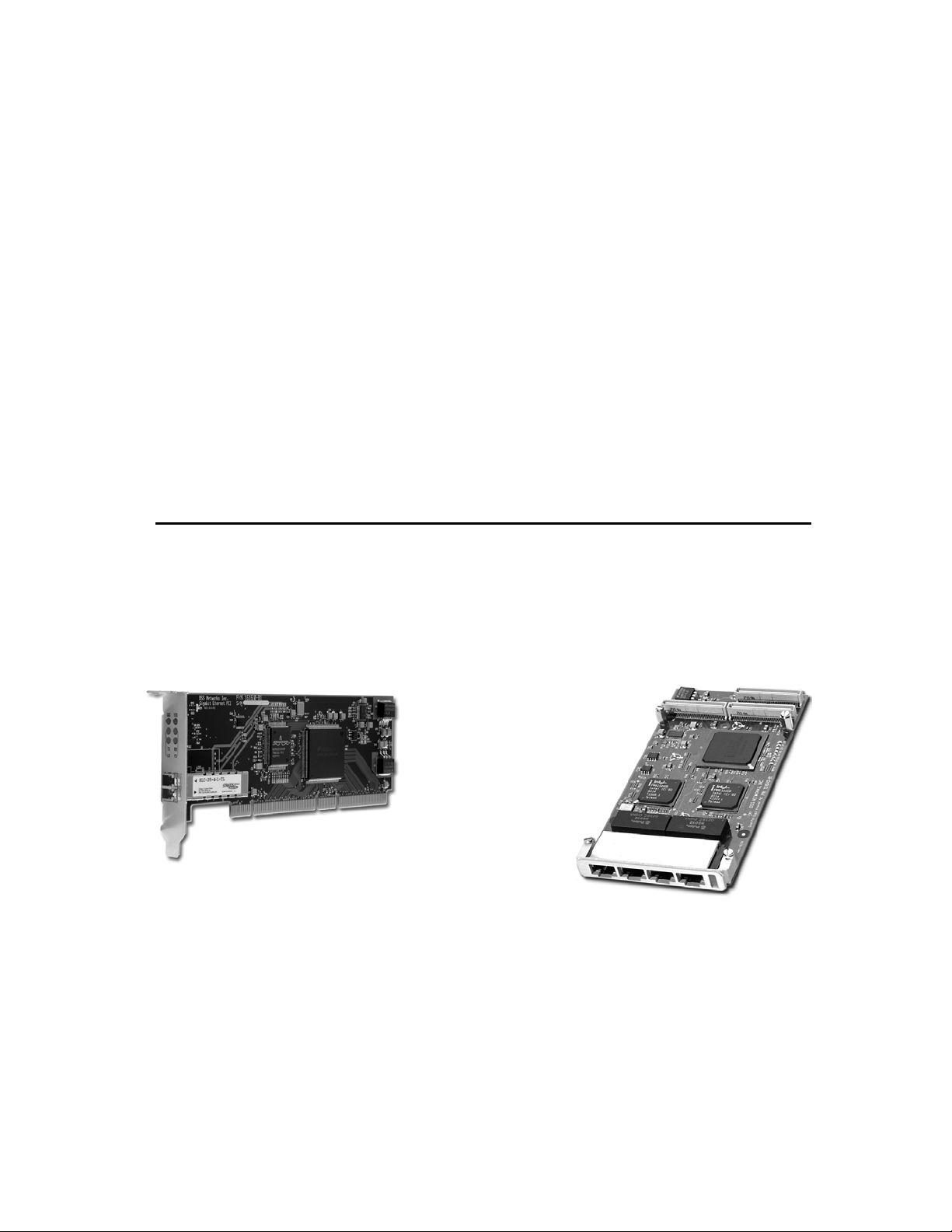
6.1 BOARD PHOTOS
Model 5161 PMC
Model 5162 - 2-port PMC Model 5164 - 4-port PMC
Model 7160 Fiber PMC
Model 6162 PCI-X - 2-port
DSS NETWORKS, INC.
Model 6161 PCI Model 6167 Fiber PCI
Version: 2.0 Page: 7
Page 8

GigMAC PMC and PCI Board and Driver Users Manual
6.2 BOARD LED INDICATORS
PCI / PMC Boards LED Function Table
Gigabit NIC
Model
PCI 6161 TX RX Quality Duplex 1000 100
PCI 6167 TX RX Quality Duplex 1000 100
PCI-X 6162 TX RX 1000 100 N/A N/A
PMC 5164 ACT ACT ACT ACT N/A N/A
PMC 5161 TX RX 10 100 1000 FD
PMC 7160 TX RX Link SD N/A N/A
PMC 5162 TX RX 1000 100 N/A N/A
Models 5161, 6161 and 6167 with RJ-45 connector
The front panel has onboard RJ-45 connectors that supports the connection of
Category 5 cabling with 6 LED indicators that provide the following as marked
with silkscreen nomenclature on front panels:
Three of the Yellow LEDs are used to indicate the link status and port speed
option: 10 Mb, 100 Mb (Fast Ethernet), and 1000 Mb (Gigabit Ethernet) modes.
The illuminated LED indicated that the link is up and established at the speed
indicated.
One yellow LED indicates Full-Duplex status if illuminated, else half-duplex.
The remaining two Green LEDs are used to indicate both transmit and receive
activity.
LED SUMMARY
Speed Link Activity Indicators
10 Mbps LED glows solid yellow
when link is detected
100 Mbps LED glows solid yellow
when link is detected
1000 Mbps LED glows solid yellow
when link is detected
Full-Duplex Link Activity Indicator
LED # 1
Green
LED # 2
Green
LED #3
Yellow
LED #4
Yellow
LED #5
Yellow
LED #6
Yellow
DSS NETWORKS, INC.
Version: 2.0 Page: 8
Page 9

GigMAC PMC and PCI Board and Driver Users Manual
Full-Duplex LED illuminates solid yellow
to indicate full duplex status
Transmit and Receive Activity Indicators
Transmit and Receive LEDs are on solid or blinking green
to indicate activity on the link (solid shows constant activity, blinking shows
intermittent activity)
Model 7160 with SC or LC connector
The front panel has onboard fiber optic connectors that supports the connection
of fiber optic cabling using 50 or 62.5 micron multimode fiber, SC or LC type
connectors with 4 LED indicators that provide the following as marked with
silkscreen nomenclature on front panels:
Two of the Yellow LEDs are used to indicate Signal Detect (SD) and Link Status
(LNK). The Signal Detect indicates the physical layer connection is established
while the LNK indicates that the auto negotiation has completed and the link is
established at the MAC and driver level.
The remaining two Green LEDs are used to indicate both transmit and receive
activity. All ports function in the same manner as shown in the Table below:
LED SUMMARY
Signal “SD” detect Indicator
On solid yellow when hardware detects valid signal from Fiber. Flashing or intermittent
yellow indicates poor signal quality and line errors.
Link “LNK” Indicator
On solid yellow to indicate auto-negotiation complete and MAC and driver level
link is up.
Transmit and Receive Activity Indicators
Transmit and Receive LEDs are solid or blinking green
to indicate activity on the link (solid shows constant activity, blinking shows
intermittent activity).
Model 6162 dual-port PCI with RJ-45 connector(s)
The front panel has two onboard RJ-45 connectors that supports the connection
of Category 5 cabling with 4 LED indicators per port that provide the following as
marked with silkscreen nomenclature on front panels:
DSS NETWORKS, INC.
Version: 2.0 Page: 9
Page 10

GigMAC PMC and PCI Board and Driver Users Manual
LED_ACT (activity)
LED_LINK (link)
LED_1000 (1000 Mb mode)
LED_100 (100 Mb mode)
Model 5162 dual-port PMC with RJ-45 connector(s)
The front panel has two onboard RJ-45 connectors that supports the connection
of Category 5 cabling with 4 LED indicators per port that provide the following as
marked with silkscreen nomenclature on front panels:
LED_1000 (1000 Mb mod)
LED_FD (full-duplex mode)
LED_TX (transmit activity)
LED_RX (receive activity)
Model 5262 dual-port or 5261 single port PMC with RJ-45
connector(s)
The front panel has two onboard RJ-45 connectors that supports the connection
of Category 5 cabling with 4 LED indicators per port that provide the following as
marked with silkscreen nomenclature on front panels:
LED_1000 (1000 Mb mod)
LED_FD (full-duplex mode)
LED_TX (transmit activity)
LED_RX (receive activity)
Model 5164 quad-port PMC with RJ-45 connector(s)
The front panel has four onboard RJ-45 connectors that supports the connection
of Category 5 cabling with one bi-color LED indicators per port that provides an
“activity” indicator.
DSS NETWORKS, INC.
Version: 2.0 Page: 10
Page 11

GigMAC PMC and PCI Board and Driver Users Manual
6.3 PMC CONNECTOR PIN/SIGNAL DEFINITIONS
PMC Connectors Pin Assignments
Pn1/Jn1 32 Bit PCI
1 TCK -12V NC 2
3 GND INITA# 4
5 INTB# INTC# NC 6
7 BUSMODE1# +5V 8
9 NC INTD# PCI-RSVD NC 10
11 GND PCI-RSVD NC 12
13 CLK GND 14
15 GND GNT# 16
17 REQ# +5V 18
19 VIO AD[31] 20
21 AD[28] AD[27] 22
23 AD[25] GND 24
25 GND C/BE[3]# 26
27 AD[22] AD[21] 28
29 AD[19] +5V 30
31 NC VIO AD[17] 32
33 FRAME# GND 34
35 GND IRDY# 36
37 DEVSEL# +5V 38
39 GND LOCK# 40
41 NC SDONE# SBO# 42
43 PAR GND 44
45 NC VIO AD[15] 46
47 AD[12] AD[11] 48
49 AD[09] +5V 50
51 GND C/BE[0]# 52
53 AD[06] AD[05] 54
55 AD[04] GND 56
57 NC VIO AD[03] 58
59 AD[02] AD[01] 60
61 AD[00] +5V 62
63 GND REQ64# 64
DSS NETWORKS, INC.
Version: 2.0 Page: 11
Page 12

GigMAC PMC and PCI Board and Driver Users Manual
Pn2/Jn2 32 Bit PCI
1 NC +12V TRST# 2
3 TMS TDO 4
5 TDI GND 6
7 GND PCI-RSVD NC 8
9 NC PCI-RSVD PCI-RSVD NC 10
11 NC BUSMODE2# +3.3V 12
13 RST# BUSMODE3# PMC_1 14
15 3.3V BUSMODE4# NC 16
17 NC PCI-RSVD GND 18
19 AD[30] AD[29] 20
21 GND AD[26] 22
23 AD[24] 3.3V 24
25 IDSEL AD[23] 26
27 +3.3V AD[20] 28
29 AD[18] GND 30
31 AD[16] C/BE[2]# 32
33 GND PMC-RSVD NC 34
35 TRDY# +3.3V 36
37 GND STOP# 38
39 PERR# GND 40
41 +3.3V SERR# 42
43 C/BE[1]# GND 44
45 AD[14] AD[13] 46
47 M66EN AD[10] 48
49 AD[08] 3.3V 50
51 AD[07] PMC-RSVD NC 52
53 +3.3V PMC-RSVD NC 54
55 NC PMC-RSVD GND 56
57 NC PMC-RSVD PMC-RSVD NC 58
59 GND PMC-RSVD NC 60
61 ACK64# +3.3V 62
63 GND PMC-RSVD NC 64
DSS NETWORKS, INC.
Version: 2.0 Page: 12
Page 13

GigMAC PMC and PCI Board and Driver Users Manual
Pn3/Jn3 32 Bit PCI
1 NC PCI-RSVD GND 2
3 GND C/BE[7]# 4
5 C/BE[6]# C/BE[5]# 6
7 C/BE[4]# GND 8
9 NC VIO PAR64 10
11 AD[63] AD[62] 12
13 AD[61] GND 14
15 GND AD[60] 16
17 AD[59] AD[58] 18
19 AD[57] GND 20
21 NC VIO AD[56] 22
23 AD[55] AD[54] 24
25 AD[53] GND 26
27 GND AD[52] 28
29 AD[51] AD[50] 30
31 AD[49] GND 32
33 GND AD[48] 34
35 AD[47] AD[46] 36
37 AD[45] GND 38
39 NC VIO AD[44] 40
41 AD[43] AD[42] 42
43 AD[41] GND 44
45 GND AD[40] 46
47 AD[39] AD[38] 48
49 AD[37] GND 50
51 GND AD[36] 52
53 AD[35] AD[34] 54
55 AD[33] GND 56
57 NC VIO AD[32] 58
59 NC PCI-RSVD PCI-RSVD 60
61 NC PCI-RSVD GND 62
63 GND PCI-RSVD NC 64
DSS NETWORKS, INC.
Version: 2.0 Page: 13
Page 14

GigMAC PMC and PCI Board and Driver Users Manual
7. POWER CONSUMPTION SPECS
PCI / PMC Boards Power Consumption Table
Gigabit NIC
Model
PCI 6161
PCI 6167
PCI-X 6162
PMC 5160
PMC 5161
PMC 7160
PMC 5162
PMC 5164
3.3V Source
Current I (mA, A)
775 785 2.55 3.92
775 785 2.55 3.92
1.17 1.70 3.86 8.5
445 485 1.47 2.42
435 465 1.44 2.33
525 567 1.74 2.83
1.45 1.60 4.80 8.0
2.34 1.80 7.90 9.0
5V Source
Current I (mA, A)
Power (P)
P = I . V (W)
8. HARDWARE INSTALLATION
Before attempting to install the GigMac Gigabit adapter into your system, please
make sure of the following:
Shut off the power to the computer and any peripherals. It is important to remove
the power cable to the computer to reduce the possibility of residual power
remaining in the power supply.
Ground yourself. Many electronic components inside computer and on the
GigMac card can be severely damaged by receiving a shock of static electricity.
Before touching any electronic components or boards, discharge any static
electricity on your body by touching the bare metal case around the power supply
inside your computer. Avoid excessive movement during the installation, such as
walking across carpets, as this can generate static. If you must leave the
installation area before the installation is complete, be sure to ground yourself
again before continuing the installation.
Assess system power requirements. If you already have other PCI cards in
your Mac, make sure that your system is able to provide the necessary power to
support the addition of the GigMac adapter card. Check your computer's user
manual for power limitations.
DSS NETWORKS, INC.
Version: 2.0 Page: 14
Page 15

GigMAC PMC and PCI Board and Driver Users Manual
8.1 INSTALLATION IN PC COMPUTER
There are many different styles and types of PC platforms that utilize PCI slots.
This section contains a generic installation procedure. Please refer to your User's
manual for more detailed instructions on installing the adapter in a PC.
The GigMAC PMC card requires a PMC-to-PCI Carrier adapter module in order
to be used in a standard PCI system. Please refer to section 2.2 below for
instructions on installing the GigMAC PMC adapter onto a mainboard carrier
adapter.
Step 1 - Shut down the power to the computer system and remove the power
cord and any peripheral cables.
Step 2 - Open the computer case. This will expose the interior of the case and
allow the adapter card to be installed. Consult your User's Manual for assistance
in opening your computer. The PCI card edge connector contains “key” notches
that correspond to dividers in the motherboard slot. It is very important to align
the key notches with the matching dividers in the slot. Failure to align the notches
correctly could cause the card or slot to be damaged.
Step 3 - Align the GigMac PCI edge connector and the system motherboard
socket as indicated in the diagram above. Once aligned, push down firmly on the
PCI card until it is completely seated in the slot. Once the GigMac adapter has
been successfully installed, close the PC case, re-attach the power cable and
any other cables that were removed for the hardware installation procedure.
Consult Section 2.3 for information on connecting the adapter to the network.
8.2 EMBEDDED OR COMPACT PCI INSTALLATION
There are many different styles and types of Embedded System platforms that
utilize PMC Mezzanine slots. This section contains a generic installation
procedure. Please refer to your User's manual for more detailed instructions on
installing the adapter in an Embedded or CompactPCI system.
Step 1 - Shut down the power to the computer system and remove the power
cord and any peripheral cables.
Step 2 – Remove the CompactPCI or Embedded Mainboard controller from the
system, if necessary to access the PMC slot. This will allow the PMC adapter
card to be more easily installed. Consult your User's Manual for assistance in
opening and removing the mainboard. The PMC card has 3 connectors labeled
JN1, JN2 and JN3. JN1 and JN2 are required for all modes of operation while
JN3 is required only for 64-bit mode. Your CompactPCI mainboard or other PMC
carrier will also contain PMC card connectors labeled JN1 and JN2, and
DSS NETWORKS, INC.
Version: 2.0 Page: 15
Page 16

GigMAC PMC and PCI Board and Driver Users Manual
optionally JN3 and JN4. JN4 is for optional user-defined I/O and is not used by
the GigMAC PMC adapter. Additionally, the mainboard may also contain either a
5 volt or 3.3 volt key to prevent voltage mismatches. Since the GigMAC PMC
card may operate from a 5 or 3.3 volt supply, it can be used in either a 5 or 3.3
volt keyed system. It is very important to align the connectors before pressing the
PMC card onto the mainboard to prevent damage to the card or slot.
Step 3 - Align the GigMac PMC connectors and the system motherboard
Connectors and push down firmly on the PMC card until it is completely seated in
the connectors on the mainboard. Once the GigMac adapter has been
successfully installed, re-install the mainboard. Re-attach the power cable and
any other cables that were removed for the hardware installation procedure.
9. COPPER CABLING AND CONNECTOR INFO
9.1. FIBER CABLE SPECIFICATIONS
Distance (Model 7160, 6167, 5261-LC, 5262-LC multimode/singlemode fiber)
(1000-base-SX 850nm multimode)
(1000-base-LX 1310nm singlemode)
1000BASE-SX/LX (850 nm Laser for multimode-SX, 1310nm laser for single-mode-LX)
Fiber Core
Diameter
62.5/125 um multi-mode 160 Mhz * km 2 to 220 m
62.5/125 um multi-mode 200 Mhz * km 2 to 275 m
50.0/125 um multi-mode 400 Mhz * km 2 to 500 m
50.0/125 um multi-mode 500 Mhz * km 2 to 550 m
8.0/125 um single-mode 500 Mhz * km 5 km
Type
Fiber
Bandwidth
Mhz* km
Distance
Connecting Fiber optic Model 7160, 6167, 5261-LC, 5262-LC
This section explains how to connect the GigMac fiber controller to the external
network using standard fiber optic cables. Typically 50 or 62.5 micron multimode
fiber optic cables with LC or SC type connectors are used depending on the
connector option. For extended distance, single-mode fiber can be used in
models equipped with extended range single-mode connectors.
DSS NETWORKS, INC.
Version: 2.0 Page: 16
Page 17

GigMAC PMC and PCI Board and Driver Users Manual
Insert the fiber optic cable into the SC or LC type connector until the self-locking
tab clicks into position. Connect the opposite end in to a 1000 Base SX switch.
Two types of cables are used when connecting the GigMac fiber controller to the
network. A workstation or "straight through" cable is typically used to connect
Ethernet adapters to switches. A fiber “crossover” cable may also be used to
connect controllers back-to-back. This configuration is useful for loopback and/or
diagnostic purposes or when a switch is not available.
9.2 COPPER RJ-45 CONNECTOR AND CABLE
Connecting Copper RJ-45 Models 5161, 5162, 5261-RJ, 5262-RJ,
5164, 6161, 6162
This section explains how to connect the GigMac controller to the external
network using the standard Category 5, 5e or 6 cables. The maximum cable
length is typically 100 meters or 328 feet.
Insert the Category 5 or 5e cable into the RJ-45 connector until the self-locking
tab clicks into position. Connect the opposite end in to a 10/100 or 10/100/1000
Base T switch. Two types of cables are used when connecting the GigMac
controller to the network. A workstation or "straight through" cable is typically
used to connect Ethernet adapters to switches. A “crossover” cable may also be
used to connect controllers back-to-back. This configuration is useful for
diagnostic purposes or when a hub or switch is not available. However, it is not
recommended for extended use, as it violates the IEEE specification for 10 Mbit,
100 Mbit and 1000 Mbit Ethernet networks.
Note(1): GigMAC Models 5161, 5162, 5164, 6161 and 6162 support “autoMDIX” mode where a crossover cable is not required when directly attaching two
controllers.
Note(2): Cables used for Gigabit networks must use all 8 wires. In 10 and 100
modes, wires are dedicated for transmit or receive while in Gigabit mode, data is
transmitted and received over all 4-pairs.
DSS NETWORKS, INC.
Version: 2.0 Page: 17
Page 18

GigMAC PMC and PCI Board and Driver Users Manual
RJ-45 pinouts for CAT5 connectors and cables are shown in the following
table:
Pin 10/100 Signal Gigabit Signal
1 Transmit+
2 Transmit- Channel A3 Receive+ Channel B+
4 Unused Channel C+
5 Unused Channel C6 Receive- Channel B7 Unused Channel D+
8 Unused Channel D+
Channel A+
10. SOFTWARE DRIVER INSTALLATION
The following sections explain how to install the driver software in VxWorks,
Linux and Windows based systems.
10.1 VXWORKS DRIVER INSTALLATION AND USAGE
This section is covered in a separate manual. Please see the vxWorks OEM
Developers Guide p/n 131901 for vxWorks software installation and integration
instructions.
10.2 LINUX DRIVER INSTALLATION AND USAGE
These instructions assume that you are running Red Hat Linux 7.x, 8.x, 9.x or a
similar Linux OS. You should be using at least a kernel version 2.4.18 installation
for any other Red Hat-based system will be similar. For other Linux based
systems, the location of some files may be slightly different.
Building the driver
To build the driver, copy the driver files to an appropriate directory. You will need
to make sure your CD is mounted.
$ mkdir dpm
$ cd dpm
$ cp /mnt/cdrom/linux-dpm-driver/dpm/dpm*.tar.gz .
$ gunzip dpm*.tar.gz
$ tar vxf dpm*.tar
DSS NETWORKS, INC.
Version: 2.0 Page: 18
Page 19

GigMAC PMC and PCI Board and Driver Users Manual
To create a new driver object module:
$ make clean
$ make
Repeat same procedure with driver utility directory as follows:
$ mkdir util
$ cd util
$ cp /mnt/cdrom/linux-dpm-driver/util/util*.tar.gz .
$ gunzip util*.tar.gz
$ tar vxf util*.tar
To create a new utility programs:
$ make clean
$ make
Note(1): If you are installing the GigMac in an SMP machine, you should
comment out the standard CFLAGS line in the “Makefile” and uncomment the
SMP version of CFLAGS before compiling the driver (safe to leave SMP enabled
on most newer versions of Linux).
Note(2): Before compiling, please also edit the Makefile and set “INCLUDEDIR”
to the path of your Linux kernel source tree. For example:
INCLUDEDIR = /usr/src/linux-2.4.25/include
Installing the driver
To install the driver object module in the file system, become root and run:
# make install
# depmod –a
# insmod dpm.o [ChipSelector=0] [ChipSelector=1]
Note(1): For loading driver with Intel 82546 based cards, use ‘ChipSelector=1’
Note(2): For loading driver with National DP83820 based cards, use
‘ChipSelector=0’ or leave blank (default)
Note(3): ‘modprobe’ may be used in place of ‘insmod’ to resolve module
dependencies.
DSS NETWORKS, INC.
Version: 2.0 Page: 19
Page 20

GigMAC PMC and PCI Board and Driver Users Manual
Configure the card using your preferred configuration tool, or edit the initialization
script for the interface directly. On Red Hat, the file /etc/sysconfig/networkscripts/ifcfg-eth0 might look something like this (substituting ethernet device
number, example: eth0, eth1, etc):
DEVICE='eth1'
BOOTPROTO='none'
ONBOOT='yes'
IPADDR=192.168.0.3
GATEWAY=192.168.0.1
TYPE=Ethernet
USERCTL=no
NETMASK=255.255.255.0
NETWORK=192.168.0.0
BROADCAST=192.168.0.255
Note: You should also add a line to /etc/modules.conf for each interface as
shown in the following example:
SAMPLE MODULES.CONF FILE
alias eth1 dpm
alias eth2 dpm
alias eth3 dpm
alias eth4 dpm
options dpm ChipSelector=1 IntrHoldOff=0
Note: In order to load the Intel driver, the "ChipSelector=1" option is required in
the 'options' field of modules.conf. Please see man page for modules.conf for
additional information on module configuration.
MANUAL DRIVER INSTALLATION
insmod ./dpm.o # to insert driver module
ifconfig eth1 192.168.0.3 # if not already configured by system
Once driver is inserted you may need to run "ifconfig" command or it may be run
automatically by the system.
MANUAL DRIVER REMOVAL
ifdown eth[n] # repeat for all 'dpm' network interfaces
rmmod dpm # to remove driver module
DSS NETWORKS, INC.
Version: 2.0 Page: 20
Page 21

GigMAC PMC and PCI Board and Driver Users Manual
LOADING THE DRIVER FOR INTEL BASED MODELS (5261, 5262, 5164, etc.)
Note: In order to load the Intel driver, the "ChipSelector=1" option is required
during the 'insmod' as follows:
insmod ./dpm.o ChipSelector=1
TUNING THE INSTALLATION
Interrupt holdoff (programmed latency)
To increase (or decrease) the value of the programmed interrupt latency, insert
the module and set the "IntrHoldOff" parameter as follows:
insmod ./dpm.o IntrHoldOff=1 # value can be 0, 1, 2 or 3
Note: A value greater than 3 is not recommended.
Other driver parameters that can be set during driver load or in
modules.conf:
MediaSpeed=10,100,1000 # Media Speed (default 1000)
SetAutoNeg=0,1 # Setting for auto negotiation (default 1=auto)
DuplexMode=0,1 # Setting for duplex (default 1=FULL)
IntrHoldOff=0,1,2 # interrupt holdoff value in 100 microsecond
units
ChipSelector=0,1 # default=0 (National), 1=Intel
NumBufDescs=<cnt> # default=256, 128, 256, 512, 1024
MaxBufferSize=<size> # default=2048, 2048, 4096, 8192
FrameGenSize=<size> # frame generator test size (64-9000 bytes)
See “Command Line Parameters” table below for additional information on driver
module insertion parameters.
DSS NETWORKS, INC.
Version: 2.0 Page: 21
Page 22

GigMAC PMC and PCI Board and Driver Users Manual
‘Insmod’ Command Line Parameters
The following parameters are used by entering them on the command line with
the modprobe or insmod command. For example, with Intel based card model
(ex. 5262, 5164, etc.) entering:
insmod dpm ChipSelector=1 IntrHoldOff=0
loads the dpm driver setting it for Intel chipset and setting the Interrupt Holdoff
latency to zero (disabled).
Parameter
Name
SetAutoNeg
DuplexMode
Valid
Range/Settings
0,1 1
0,1,2
(0=half, 1=full,
2=both)
Default Description
This parameter specifies the enabling of auto
negotiation.
Defines the direction in which data is allowed
to flow. Can be either one or two-directional.
1
If both. If auto negotiation is enabled, defines
modes advertised. If auto negotiation is
disabled sets duplex to this value.
PauseFlowEn
IntrHoldOff
MediaSpeed
NumBufDescs
MaxMtuSize
0, 1 1
0, 1 or 2 (0=off) 1
10, 100, 1000 1000
80 - 4096 256
1500-9600 1500
This parameter enables or disables pause
frame flow control (typically enabled).
This value delays the generation of receive
interrupts in units of 100 microseconds.
Receive interrupt reduction can improve CPU
efficiency if properly tuned for specific
network traffic. Increasing this value adds
extra latency to frame reception and if set too
high could decrease the throughput of TCP
traffic.
If auto negotiation id disabled, speed forces
the line speed to the specified value in
megabits per second (Mbps). If auto
negotiation is enabled, sets the highest
speed advertised.
(adapters using copper connections only)
This value is the number of transmit and
receive descriptors allocated by the driver.
Increasing this value allows the driver to
queue more transmit and receive buffers.
Each descriptor is 16 bytes.
This value is the maximum mtu size
supported in the driver.
MaxBufferSize
DSS NETWORKS, INC.
2048, 4096,
8192, 16384
2048
Sets the maximum buffer size supported in
the driver.
Version: 2.0 Page: 22
Page 23

GigMAC PMC and PCI Board and Driver Users Manual
Setting this parameter to one instructs the
AccAllUni
0, 1 0
driver to receive all unicast frames
(sometimes useful in frame generator
testing). Do not enable for normal traffic.
ChipSelector
FrameGenSize
0, 1 0
60-MaxMtuSize 1500
Sets the chipset selector (0=National,
1=Intel). Default is National chipset.
Sets the frame generator frame size for
testing end-to-end or loopback.
FUNCTIONALITY TESTING
When the driver is loaded into the system via `insmod' it probes the PCI bus to
locate all DP83820 devices, and creates control structures for each. The driver
logs a couple of messages available in `/var/log/messages' for each device with
information about its PCI geographic location, IRQ, IO address, and some basic
debug information (addresses of some important structures).
All the devices on the PCI bus can be listed by,
# cat /proc/pci
# cat /proc/interrupts
IRQ and IO address information from this can be correlated with the information
displayed by the driver in `/var/log/messages'
When the TCP/IP stack is initialized, it opens all configured ethernet devices, and
initializes them for use. At this time, the driver will perform auto negotiation and
log information about the link status. The driver can then be tested by running
ping, telnet, ftp, NFS etc.
Suggested basic verifications to be run
lsmod # lists loaded drivers
ifconfig # lists configured network interfaces
dmUtil -s eth[n] # prints low-level driver statistics for device
ping <ip addr> # ping to remote station to verify
ADDITIONAL VERIFICATION AND PERFORMANCE TESTING
Verification and performance testing can be done using the Linux "uxBlaster" and
"uxBlastee" test programs found on OEM developer kit CD. The 'dmUtil' utility
program also found on the CD can be used to obtain valuable information used
for debug and integration verification.
DSS NETWORKS, INC.
Version: 2.0 Page: 23
Page 24

GigMAC PMC and PCI Board and Driver Users Manual
dmUtil -s eth0 # displays low-level driver statistics
dmUtil -m eth0 # displays DP83820 MAC controller registers
dmUtil -p eth0 # displays gigabit (phy) transceiver registers
dmUtil -e eth0 # displays eeprom
dmUtil -a eth0 # displays mac address
dmUtil -ms eth0 # displays mac stats (Intel only)
LOOPBACK PERFORMANCE TESTING
1. Edit 'Makefile'
2. Un-comment the following define:
CFLAGS += -DNS_FRAME_TEST -DIN_FRAME_TEST
3. Save file, unload and reload driver using procedures described above.
4. Use "ifconfig" command to bring up Ethernet interface.
5. Run the following command from the 'util' directory:
./dmUtil -l eth1 # loopback eth0, eth1, etc.
6. View statistics using dmUtil command as follows:
./dmUtil -s eth1 1 # second arg=1 zeroes statistics after gathering
Note: The driver must be compiled without "-DNS_FRAME_TEST" for normal
operation.
Jumbo frames: The mtu size can be increased using the ifconfig utility, as
follows:
# ifconfig <interface-name> mtu <mtu-size>
Example: ifconfig eth0 mtu 3000
Note: Use of jumbo frames is not recommended as it is not IEEE standard and
many switches do not support the forwarding of jumbo frames. It also has to be
enabled and negotiated on both ends of the connection and in today’s faster
systems, using jumbo frames offers little performance improvement and may only
be useful in closed application-specific networks.
DSS NETWORKS, INC.
Version: 2.0 Page: 24
Page 25

GigMAC PMC and PCI Board and Driver Users Manual
Using dmUtil dpm driver utility:
The “dpm driver utility” is used to capture detailed board levels statistics,
controller registers and to set loopback mode. Example usage of the “dmUtil” are
as follows:
dmUtil -s eth1 # get driver statistics for interface 1
dmUtil –p eth1 # get phy (transceiver) registers for interface 1
dmUtil –m eth1 # get MAC (PCI controller) registers for interface 10
dmUtil –t eth1 # get execution debug trace for interface1
(DEBUG_FLAGS trace option must be compiled in)
dmUtil –e eth1 # get eeprom configuration settings
dmUtil –ms eth1 # get mac MIB statistics
dmUtil –a eth1 # get mac address
dmUtil –w eth1 <0,1,2> # write default eeprom configuration to controller
dmUtil –l eth1 <arg> # set controller in internal loopback mode
(driver must be compiled with –DNS_FRAME_TEST
in Makefile). Arg=1 for enable, 0 for disable.
DSS NETWORKS, INC.
Version: 2.0 Page: 25
Page 26

GigMAC PMC and PCI Board and Driver Users Manual
10.3 DPM DRIVER MANAGEMENT API
The dpm network driver management API is an api extension primarily used by
the ‘dmUtil’ command line utility to enable various management functions or to
acquire driver status and statistics. The typical api usage sequence is as follows:
1. User enters ‘dmUtil’ command and parameters as shown in the following
example:
./dmUtil –s eth1
2. dmUtil parses command line and prepares an “ioctl” request block to send
to driver. A pointer to a application buffer to hold the text message results
(for example formatted statistics) is provided by dmUtil in the request
block.
3. Driver receives ioctl request block performs action and copies result data
to applications message buffer.
The following is an API description of the management ioctl commands issued to
the driver from the ‘dmUtil’ application’s viewpoint:
A. Opening a socket for management API
int s;
s = socket (PF_INET, SOCK_STREAM, 0);
B. Create request block for driver ioctl
struct ifreq ifr;
int subCmd;
NpkUserCtl myIoc;
char myDataBuf[MAX_LINES * MAX_LINE_LEN];
/* set interface name */
strcpy (ifr.ifr_name, “eth1”);
/* set ioctl sub-type */
subCmd = DM_IOCTL_GET_STATS;
/* set command argument */
myIoc.arg1 = 0;
myIoc.dataItm = (u_int) myDataBuf;
ifr.ifr_data = (char *) &myIoc;
DSS NETWORKS, INC.
Version: 2.0 Page: 26
Page 27

GigMAC PMC and PCI Board and Driver Users Manual
C. Issue ioctl command
/* issue ioctl to network driver */
err = ioctl (s, SIOCDEVPRIVATE + subCmd, &ifr);
D. Check and print results
if (err < 0)
{
/* perror (errno); */
usage ();
exit (1);
}
if (subCmd == DM_IOCTL_GET_TRC)
{
print_trace();
}
else
{
if ((subCmd != DM_IOCTL_SET_LOOP_MODE) &&
(subCmd != DM_IOCTL_PROG_EEPROM))
printf ("\n%s\n", myDataBuf);
}
IOCTL COMMAND SUB-TYPES
/* get driver trace buffer */
#define DM_IOCTL_GET_TRC 1
/* get driver statistics */
#define DM_IOCTL_GET_STATS 2
/* get phy registers */
#define DM_IOCTL_GET_PHY_REGS 3
/* get mac registers */
#define DM_IOCTL_GET_MAC_REGS 4
/* set loopback mode */
#define DM_IOCTL_SET_LOOP_MODE 5
Additional arguments:
arg1=0 Disable loopback
arg1=1 Enable loopback
/* read eeprom */
#define DM_IOCTL_READ_EEPROM 6
/* program eeprom */
#define DM_IOCTL_PROG_EEPROM 7
/* get mac address */
#define DM_IOCTL_GET_MAC_ADDR 8
DSS NETWORKS, INC.
Version: 2.0 Page: 27
Page 28

GigMAC PMC and PCI Board and Driver Users Manual
/* dump buffer descriptors */
#define DM_IOCTL_DUMP_BDS 9
/* get mac MIB statistics */
#define DM_IOCTL_GET_MAC_STATS 10
Please also see example code in dmUtil.c for additional information.
10.4 WINDOWS DRIVER INSTALLATION
This chapter describes the installation of the GigMac in Windows 2000/98/ME
environment. Before attempting to install the software, make sure your system
settings match the system requirements listed in Chapter 1.
The Hardware Wizard in Windows 98, and the Found New Hardware Wizards of
Windows 2000 and Windows Me makes the installation processes of these
programs very similar. Before installing the GigMac driver, make sure the
hardware has been installed properly, and the adapter is connected to the
network with the appropriate network cables. For information on connecting
network cables to the GigMac Ethernet adapter, please see the "Connecting to
the GigMac" section presented earlier in this manual.
Step 1 - Once the hardware is installed, reconnect the power and network cables
and turn on the power to the computer.
The Hardware Wizard will detect the card. Click the Next> button to continue
Installation and proceed to Step 2 below. If the Wizard does not detect the card,
please goto to Control Panel->Add/Remove Hardware. Click Next> and select
Add/Troubleshoot Device. At this point the system may find your device or you
may have to select it manually from the list. Then select Update Driver.
Step 2 - The Hardware Wizard will search for new software for the hardware it
has detected. Click Next> to continue installation.
Step 3 - The Hardware Wizard will ask you what you wish to do. Click Next> to
accept the Recommended option and continue installation.
Step 4 - The Hardware Wizard will ask where you wish to search for drivers.
Click the "Specify a location" option. Insert the DSS Networks GigMac Gigabit
Ethernet Adapter CD. Click Browse and select the CD. Select the appropriate
Windows directory and Click Next to continue.
Step 5 - The Hardware Wizard will find the driver and list the path to the INF file.
Click Next to continue installation. If the Wizard indicates more than 1 possible
driver, please make sure you have selected the one from the installation CD.
DSS NETWORKS, INC.
Version: 2.0 Page: 28
Page 29

GigMAC PMC and PCI Board and Driver Users Manual
Step 6 - The Hardware Wizard will ask you to configure Advanced Features for
your adapter. For most users, the default settings are sufficient. Click OK to
accept the default settings.
Step 7 - The Hardware Wizard may ask you to insert your Windows 98,
Windows 2000 or Windows Me CD and then click OK. One Windows 2000, this
step may not be necessary as all of the necessary files may be on your hard
disk. If needed, insert the Windows CD and Click OK. The Hardware Wizard may
copy files from the Windows CD.
Step 8 - The Hardware Wizard will finish installing the adapter software. Click
Finish to continue the installation.
Step 9 - The Hardware Wizard may ask you to restart your computer. Click Yes
to reboot your computer and complete your installation. The installation of your
DSS Networks GigMac Gigabit Ethernet Adapter is now complete.
11. TESTING AND VERIFICATION
There are several ways to test your adapter on vxWorks, Linux and Windows
platforms. This section provides suggestions on how you may test and verify your
installation. Before you can proceed with any of the suggested tests, you must
have previously configured your TCP/IP protocols and interfaces on your
computer. Please refer to your online help and User Manuals for your particular
system on instructions on setting up your TCP/IP environment.
ICMP Ping. Ping is a simple verification method and it very useful for
verification of cabling, adapter configuration and system configuration of the
TCP/IP protocol software. You can also specify a “fast ping” and larger
message sizes in order to more effectively test the protocols and adapter
interface.
FTP File Transfer. FTP is also an available method for testing your
installation. FTP allows you to test by transferring files of different sizes.
Using large file transfers is a good way to test medium transfer rates through
the protocol stack.
HTTP Web Browsing. Is a good means of testing the protocols and interface
to the adapter.
Telnet. Using Telnet you can log into another system and invoke commands
to send a receive data. You can also test multiple connections within a single
Window by repetitively Telnet’ing back and forth between multiple systems.
DSS NETWORKS, INC.
Version: 2.0 Page: 29
Page 30

GigMAC PMC and PCI Board and Driver Users Manual
Windows Explorer. In a Windows environment, you can also use the
Windows explorer to access files on other systems within your Workgroup or
Domain.
Blaster / blastee can be used to perform TCP throughput tests between
VxWorks, Linux and Windows platforms. These test programs are included on
the OEM developer CD.
Internal loopback: The vxWorks and Linux drivers can be placed into
internal loopback for a full-speed raw driver and controller throughput test.
This is very useful for getting a baseline throughput measurement and also
for verifying the robustness of the controller and driver in your system.
12. SPECIFICATIONS
Connector (Models 5161, 5162, 5261-RJ, 5262-RJ, 5164, 6161, 6162): Gigabit
Ethernet (1000BaseT, 100BaseTX, 10BaseT): RJ-45 CAT5
Connector (Model 7160, 6167 Fiber): SC or LC connector type for 50 and 62.5
micron multimode fiber.
Connector (Model 5261-LC, 5262-LC Fiber): LC connector type for 50 and 62.5
micron multimode fiber.
Drivers:
Microsoft XP Embedded
Linux 2.4 (all versions)
Tornado 2.0.2 and Tornado 2.2 (VxWorks 5.4/5.5)
Status Indicators (models 5161 and 6161, 6167): 1000 Mbps Link, 100 Mbps
Link, 10 Mbps link, Full-Duplex, Transmit and Receive Activity
Status Indicators (model 7160 fiber): Signal Detect, Link, Transmit and
Receive
Status Indicators (model 6162 PCI): Link, Activity, 1000 Mbps, 100 Mbps
Status Indicators (model 5162 PMC): 1000 Mbps, 100 Mbps. Transmit and
Receive
Status Indicators (model 5164 PMC): Link/Activity (all four ports)
Microsoft Windows 2000 Professional
DSS NETWORKS, INC.
Version: 2.0 Page: 30
Page 31

GigMAC PMC and PCI Board and Driver Users Manual
Status Indicators (model 5261/5262 PMC): Link/1000, Full-Duplex, Transmit,
Receive
Bus Interface: PCI v2.2 bus master, 32/64-bit, 33/66 MHz
PCI-X (Model 6162)
Dimensions: (PMC Models 5161, 5162, 5164, 7160, 5261, 5262):
5.866” X 2.913
Dimensions: (PCI models 6161, 6162, 6167):
6.6” X 2.535”
PCI Power supply voltage: 5V or 3.3V (factory optioned), 5V is default
PCI signaling voltage: 5V and 3.3V
Performance Throughput (PCI 64/66): 245 Mbytes/sec (1.96 Gb) (full-duplex)
sustained
Performance Throughput (PCI 32/33): 118 Mbytes/sec (944 Mb) full or half
duplex sustained
Maximum frame rate: Over 850,000 frames per second sustained per port
Burst Rate: Up to 256 dwords (1024 bytes) over PCI bus
Host Offloading: IPv.4 checksum (UDP, TCP and IP) and optional statistics
gathering for RFC 1213 (MIB II), RFC 1398 (Ether-like MIB), IEEE
802.3 LME
Optional: Jumbo packets, 802.3x full duplex flow control with
automatic pause and priority with multiple priority queues
Link Quality Monitor: Continuously adapts to actual line conditions
by managing echo and crosstalk cancellation,
equalization, timing and skew compensation.
Automatic Gain Control maximizes signal strength
Environmental Range:
Operating Temperature: 0º to 60ºC
Relative Humidity: 10% to 90%, non-condensing
Power: Model 5161 – 3.3W @3.3V
Model 7160 – 2.6W @3.3V
Model 6160 – 4W @ 3.3V
DSS NETWORKS, INC.
Version: 2.0 Page: 31
Page 32

GigMAC PMC and PCI Board and Driver Users Manual
Voltage: 5 or 3.3 volts
MTBF:
Model 5161 – 350,000 hours
Model 7160 – 250,000 hours
Model 6160 – 300,000 hours
Model 5261 – 300,000 hours
Model 5262 – 300,000 hours
Environmental Standards Compliance (pending):
FCC Part 15, Class B
EN 55022; 1998 Class B
EN 50082-1
CE Mark
Standards Compliance:
Network: IEEE 802.3u Auto Negotiation and parallel detection
IEEE 802.3ab Gigabit Ethernet over 4 pairs of UTP Category 5
(1000BaseT) Gigabit
IEEE 802.3z Gigabit Ethernet over 1000 Base SX multimode fiber
IEEE 802.1D and 802.1Q as applicable for VLAN priority queuing
Ethernet Cable or EIA/TIA-568A Category 5E recommended.
IEEE 802.3u Fast Ethernet over 2 pairs of UTP Category 5 (100BaseTX).
IEEE 802.3 Ethernet over 2 pairs of UTP Category 3 (10BaseT).
IEEE 1386 Draft 2.2 PMC Mezzanine Standard
Full Duplex: Support for 10/100/1000 Mbps data rates on all copper models
(fiber models Gigabit mode only)
Virtual Network: Virtual LAN (VLAN) tag support
Distance (Models 5161, 5162, 5261, 5262, 5164, 6161 and 6162 copper):
Recommended maximum distance is 328 feet (100 meters).
DSS NETWORKS, INC.
Version: 2.0 Page: 32
Page 33

GigMAC PMC and PCI Board and Driver Users Manual
13. WARRANTEE AND SUPPORT INFO
Technical Support and Warranty:
Telephone technical support (8AM to 6PM, MST), 24-hour support via web email
1 year product warranty on controller hardware
Contacting Us
You may contact DSS Networks in one of several ways: via the Web, e-mail, fax
or telephone.
Technical Support
Send all technical support queries to [email protected] or visit the DSS
Networks website at
contains technical as well as sales literature for all of our products.
Technical Support-Worldwide
+1.888.506.7651
Technical Support-Fax
+1.949.727.2498
Main Corporate Telephone Numbers
949-727-2490
www.dssnetworks.com
. The DSS Networks website
DSS NETWORKS, INC.
Version: 2.0 Page: 33
 Loading...