

Page 1
ISOSTEM
DSP
ECIALISTS
High end multichannel from stereo
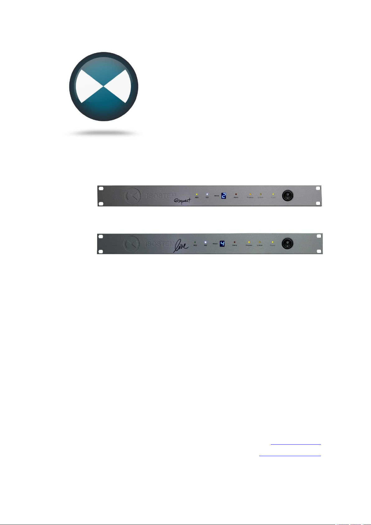
ISOSTEM Expert
ISOSTEM Live
User Manual
Manual version: v1.2
Firmware version: Min. v3.0
GUI software version: Min. v3.0
Digitale Audio- und Messsysteme GmbH
Helmholtzstr. 2-9 L
D-10587 Berlin
www.isostem.de
www.dspecialists.de
Content
Page 2

ISOSTEM USER MANUAL
2 Content
Page 3

ISOSTEM USER MANUAL
CONTENT
Content ...................................................................................................... 3
Safety Instructions...................................................................................... 5
Introduction ................................................................................................ 6
Quick Start ................................................................................................. 8
1. Necessary Items ....................................................................... 8
2. Software installation ................................................................. 8
3. Cabling & Power On ................................................................. 9
4. Software Launch & Connection ................................................ 9
5. Hardware Init & Preset Selection .............................................10
6. Listening ..................................................................................11
System Overview ......................................................................................12
DSP Technology .........................................................................12
Audio Processing ........................................................................12
Hardware ..................................................................................................14
Front Panel ..................................................................................14
Rear Panel Connectors ...............................................................15
Synchronization ...........................................................................16
GUI Software Reference ...........................................................................17
"Hardware" Tab ...........................................................................17
Com ...................................................................................................17
Sync ...................................................................................................18
Firmware ............................................................................................19
Automation .........................................................................................21
"Admin" Tab ................................................................................24
Read/Write .........................................................................................24
File Backup ........................................................................................26
Content 3
Page 4

ISOSTEM USER MANUAL
Write Protection ................................................................................. 26
Factory Reset .................................................................................... 26
"Expert" Tab (Expert hardware version only) .............................. 27
Panoramic Analyzer (PA) .................................................................. 28
Virtual Microphone (VM) .................................................................... 31
Multifunctional Area ........................................................................... 33
Monitoring and Bypass functions ....................................................... 39
Phase, ISO and Master functions ...................................................... 41
ISOSTEM® Live - Integration .................................................................... 42
Scope ......................................................................................... 42
Single Device Audio Routing and Alarm Function ....................... 42
Daisy-Chained Audio Routing and System States ...................... 43
Parallel Setup for 24/7-Operation ................................................ 45
Preset Recall Synchronization .................................................... 46
Preset Management Synchronization ......................................... 46
Appendix .................................................................................................. 47
Appendix A: Interface Specification ............................................ 47
GPI Port ............................................................................................ 47
Link Port ............................................................................................ 48
RS232 ............................................................................................... 48
Alarm Port ......................................................................................... 49
Word Clock Input ............................................................................... 49
AES/EBU Interface ............................................................................ 49
Appendix B: Schematic Block Diagram ....................................... 50
Appendix C: Factory Presets ...................................................... 52
Appendix D: Panoramic Analyzer Physics .................................. 53
4 Content
Page 5
ISOSTEM USER MANUAL
SAFETY INSTRUCTIONS
This symbol, wherever it appears, alerts you to the
presence of uninsulated dangerous voltage inside the
enclosure – voltage that may be sufficient to constitute
a risk of shock.
This symbol, wherever it appears, alerts you to important operating and maintenance instructions in the
accompanying literature. Read this manual.
CAUTION: To reduce the risk of electrical shock, do not remove any
screws of the enclosure. There are no user serviceable parts inside. Refer
servicing to qualified personnel only.
WARNING: To reduce the risk of fire or electrical shock, do not expose this
appliance to rain or moisture.
1. To assure best performance, please read this manual carefully.
2. Connect this appliance to a grounded AC outlet of 90 V to 250 V,
47 Hz to 63 Hz.
3. Keep the power cord in good condition. If the power cord becomes
damaged, discard and replace it. Never isolate the ground of the AC
power cord.
4. The power fuses are located on the rear panel of the appliance and
may be accessed from the outside. In case the fuses have to be exchanged only use fuses of the same type as labeled.
5. The power switch of the device is located on the front panel of the
appliance. The ON and OFF states are marked by “1” and “0” respectively.
6. Install this unit in a well ventilated, cool, dry and clean place. Keep it
away from direct sunlight, heat sources, vibration, dust, moisture, or
cold. In a cabinet allow about 2.5 cm of free space all around this
unit for adequate ventilation.
7. The appliance must be adapted slowly to extreme temperature
changes. These extreme changes may cause moisture inside that
can cause failure and/or electrical shock.
8. Prolonged exposure to high volume levels may cause hearing damage and/or loss. The use of hearing protection in high volume situations is recommended.
Safety Instructions 5
Page 6

ISOSTEM USER MANUAL
INTRODUCTION
For many years now, TV technology has been developing at a rapid pace.
Television in HD, 3D and surround is no longer merely a cinema experience, but can also be enjoyed in the comfort of your own home. The extremely high picture quality has also led to demands for improved sound,
providing the broadcasting corporations with a considerable challenge either a great deal of the material only exists in stereo and the original recordings are no longer available or creating a new mix on Surround 5.1
would be very expensive. As the consumer is no longer satisfied with stereo or alternating sound formats, what is now needed is an option for converting the stereo information into a multichannel surround signal in real
time.
ISOSTEM® uses complex algorithms to automatically generate a multi-
channel version out of a stereo source signal - in real time at a very low
latency of 40 ms and with perfect audio quality.
ISOSTEM® analyses the acoustic energy distribution of a stereo signal and
separates dominant sources from ambient spaces by dynamic filtering (Eu-
ropean patent office reference FR 2908586). These parts are distributed to the
5 channels and create a convincing surround signal. With ISOSTEM®,
broadcasters can produce a continuous surround program - independent of
the source material format.
In addition, ISOSTEM® exclusively offers management of the intermix (the
difference between the downmix of the multichannel signal and the reference stereo signal) to assure the compatibility of the produced signals.
(European patent office reference EP 2046076).
ISOSTEM® ensures that the EBU R.128 Programme Loudness of the origi-
nal signal remains in the upmix and downmix results accurately.
Two hardware variants of ISOSTEM® are available: ISOSTEM®Expert
contains a full range of functions and setting parameters. Individual setups
can be created using the ISOSTEM® GUI software and saved as presets.
ISOSTEM®Live was created for daily broadcast use where creating indi-
vidual presets is not a relevant option. This version can use the factory presets as well as any other presets created on an ISOSTEM®Expert unit.
Both hardware variants are delivered with a GUI software that runs on Microsoft® Windows computers. The software is used for the real time configuration of all parameters, while the 1U hardware unit performs the necessary signal processing.
6 Introduction
Page 7

(This page is intentionally left blank)
ISOSTEM USER MANUAL
Introduction 7
Page 8
ISOSTEM USER MANUAL
QUICK START
Before going into the system's details, here is what you need to do to carry
out a quick trial:
1. NECESSARY ITEMS
Check that you have the following items available:
· ISOSTEM® hardware unit (Expert or Live version)
· Power cable (supplied)
· USB to RS232 adapter cable (supplied)
· CD-ROM with ISOSTEM® GUI software (supplied)
· Driver CD-ROM for USB-to-RS232 adapter (supplied)
· A computer running Microsoft Windows® 2K/XP/Vista/7 (32-/64-bit)
operating system with one free USB port
· Stereo audio source with AES3 digital output (2 channels)
· 5.1 surround playback system with 3 digital AES3 audio inputs (six
channels)
· D-Sub 25 breakout cable (Tascam Pinout) to connect the source
and the playback system to the ISOSTEM® hardware
2. SOFTWARE INSTALLATION
· USB to RS232 adapter: Install the appropriate driver of the USB-to-
Serial converter which has been delivered with the unit. You find the
drivers in the USB-to-Serial-Converter subfolder of the ISOSTEM
CD-ROM provided with the hardware unit.
· ISOSTEM®software: The ISOSTEM® software is provided on the
supplied CD-ROM. Alternatively download the software from the website http://www.isostem.de/en.
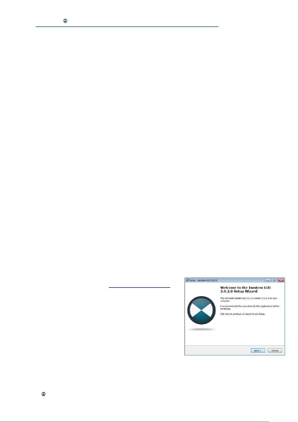
Start the installation procedure by execution of the
file “setup_XXX.exe”
After a successful installation you find the two GUI
applications “Isostem Expert” and “Isostem Live” in
the start menu of Windows.
®
Use the expert version of the executable to connect
to the Expert hardware variant and the live version
to connect to the Live variant.
8 Quick Start
Page 9
ISOSTEM USER MANUAL
3. CABLING & POW ER ON
· Connect a digital stereo audio source to the "AES In 4" connector of
the D-Sub 25 breakout cable.
· Connect 3 digital AES3 inputs (6 channels) of your surround monitoring system to the "AES Out 1", "AES Out 2" and "AES Out 3"
connectors of the D-Sub 25 breakout cable. Connect the breakout
cable to the unit's AES/EBU I/O port. Use this channel scheme:
L: AES Out 1 L R: AES Out 1 R
C: AES Out 2 L LFE: AES Out 2 R
LS: AES Out 3 L RS: AES Out 3 R
· The USB-to-RS232 adapter provided should already be connected
to a USB port on your computer (see above chapter). If not, connect
it now. Next, connect the adapter to ISOSTEM®'s RS232 port.
· Use the power cable to connect the ISOSTEM® hardware to a
mains outlet.
· Power on the ISOSTEM® hardware using the mains switch on the
rear side of the unit.
4. SOFTWARE LAUNCH & CONNECTION
From the Windows start menu execute the GUI program “Isostem Expert”
or “Isostem Live” whichever suits your device variant.
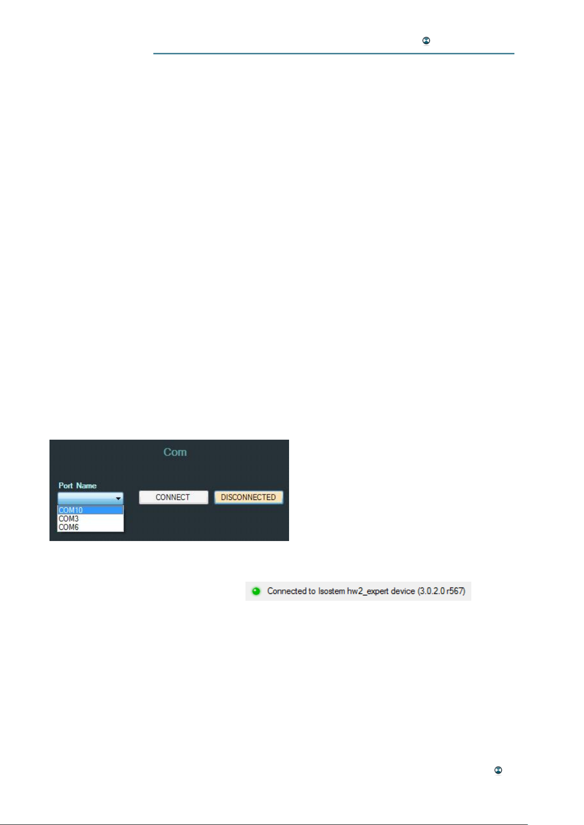
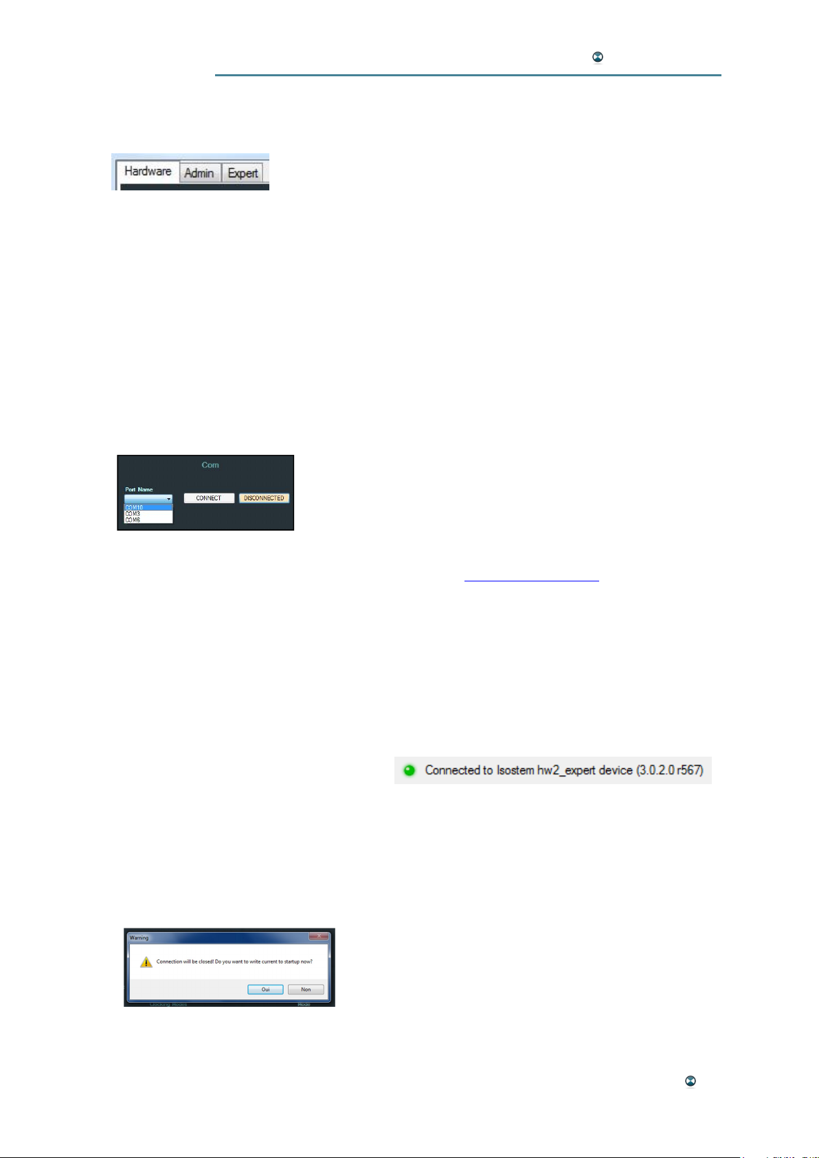
In the GUI window, the "Hardware" tab
should be selected. In the "Com" section (top
left), use the "Port Name" option to select the
COM port that your USB to RS232 adapter
emulates. Press the "CONNECT" button. If
the button changes to "CONNECTED", the
communication between the GUI software
and the ISOSTEM® hardware has been established successfully and you should see a message like this in the topmost GUI area:
If no connection has been established, try another COM port ("Port Name"),
be sure you have started the GUI variant which suits your hardware variant
and press the "CONNECT" button once more.
Quick Start 9
Page 10
ISOSTEM USER MANUAL
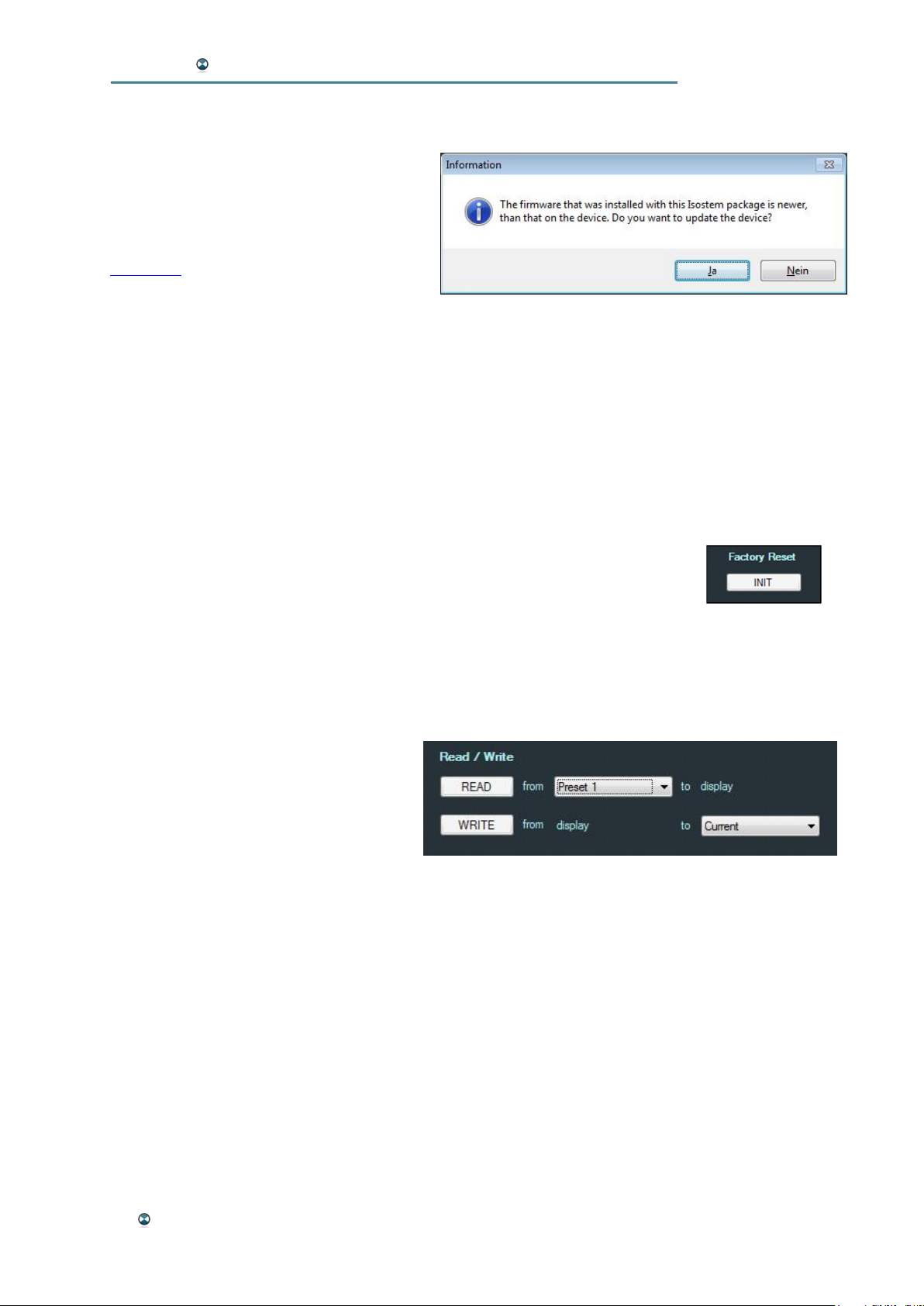
After a successful connection the GUI may detect an older device firmware.
In this case following message comes up:
It advises to update the firmware. Of
course you may reject the update.
The update procedure is explained in the
Firmware section.
5. HARDWARE INIT & PRESET SELECTION
If your ISOSTEM® unit has been used by others before, it might be a good
idea to reset it to factory defaults first.
Please note: Doing so will erase all internal user-specific presets as well
as the unit's startup configuration and overwrite it with the factory defaults.
· In the top left-hand section of the GUI, press the "Admin" tab.
· In the top right-hand GUI section, press the "Init" button below "Fac-
tory Reset". If sure, confirm both confirmation request windows.
Now, your hardware will use the factory default configuration.
Next, load a preset. This is a 2-step process: First, load a preset to the GUI
interface. Then, transmit this preset to the hardware. Here's how:
· If not yet selected, press the "Admin" tab in the top left-hand section
of the GUI.
· The Read/Write area used for
preset management is positioned directly below the tabs.
For our example, let's select
"Preset 1" behind "from" in the
first line. Press the "READ" button. The preset is loaded to the GUI
now and all parameters are displayed in the Admin window.
· Select "Current" behind "to" in the second line. Press the "WRITE"
button. This transfers the preset settings to the hardware. The transfer is confirmed by a pop-up window. Additionally the front display of
the unit shows the active preset number.
10 Quick Start
Page 11

ISOSTEM USER MANUAL
6. LISTENING
· Start your external signal source to play back some stereo audio.
· Switch your surround monitoring system on. Starting with a low vol-
ume setting in order to protect your speakers and your ears, set
your desired playback level.
· You should hear a 5.1 surround signal now that has been generated
by ISOSTEM® using your stereo source.
· Follow the steps above to load preset 3. Compare the results.
Please note: At this point, there is no need to care about the clock synchronization of ISOSTEM®'s AES input. ISOSTEM® uses sampling rate
converters (SRC) in all inputs if necessary to obtain proper sync. However,
your playback system must be synced to one of the ISOSTEM®'s AES outputs if it does not use SRCs on its own.
· Switch the GUI to the "Expert" tab ("Expert" model only). In the lower middle section of the window, there are Mute and Solo switches
for each loudspeaker channel available. Among others, they can be
useful for listening to discrete channels. In the "Monitor" section below, switching between "Surround" and "Stereo" alternatively lets
you compare the original stereo source and the 5.1 ISOSTEM® output.
Please note: To learn more about the parameters for individual fine tuning
of the upmixing process, please refer to the "Expert" Tab chapter.
Quick Start 11
Page 12
ISOSTEM USER MANUAL
SYSTEM OVERVIEW
DSP TECHNOLOGY
The signal processing is carried out by an energy saving "Sharc" Analog
Devices DSP. With just 3W power consumption, no ventilation is needed
and the risk of overheating is reduced significantly. The high-performance
system handles 32 bit real-time audio processing while the dynamic filtering
variables are 64 bit. The conversion modules calculation (up and down) is
executed in the frequency domain with phase control.
AUDIO PROCESSING
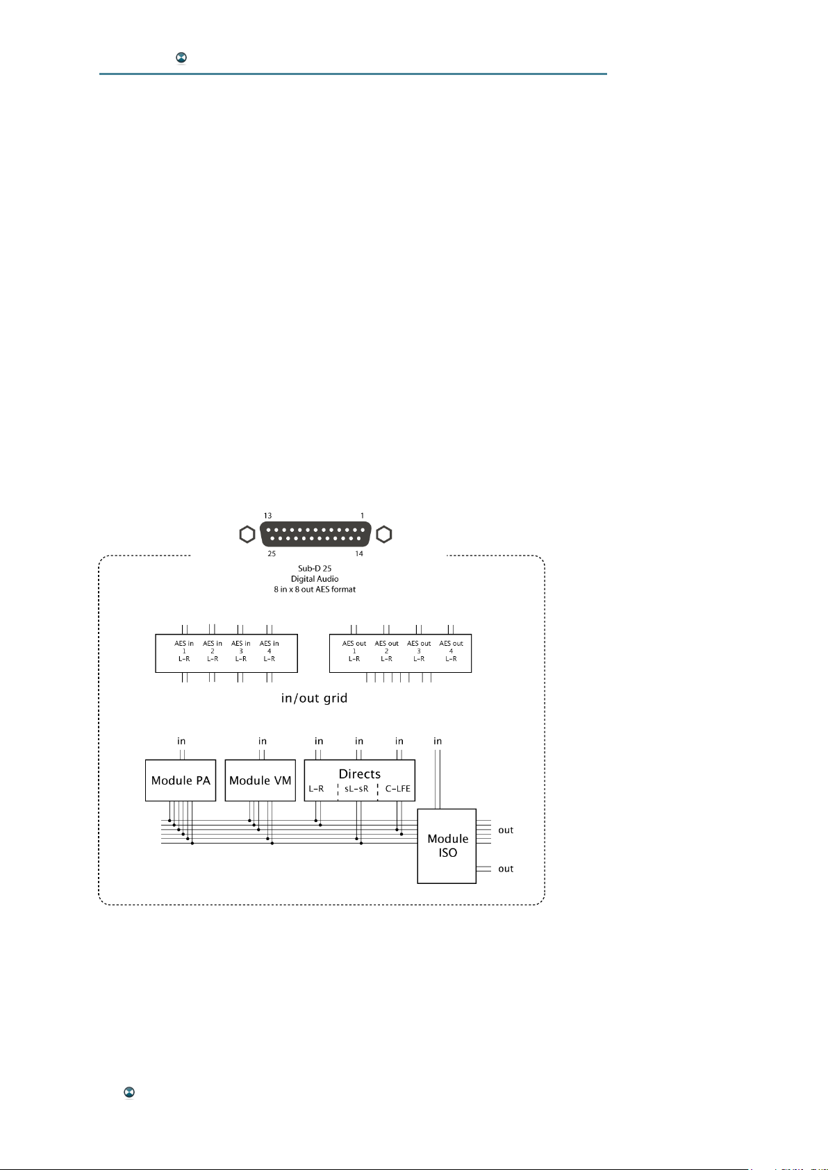
ISOSTEM® features 4 digital audio inputs in AES3 format (8 channels) as
well as 4 digital audio outputs in AES3 format (8 channels). All AES inputs
are fitted with sample rate converters (SRC) that can simplify system integration considerably. Flexible input and output matrices enable flexible I/O
routing to and from the internal audio processing modules. This allows for
compatibility with the various surround channel schemes used in environments such as TV (ITU) or cinema (SMPTE).
The two main audio processing modules "Panoramic Analyzer" (PA) and
"Virtual Microphone" (VM) are both independent upmixing stages using
different approaches with 2 audio inputs and 6 (5) audio outputs. Together
with the "Direct" module, they feed an internal bus that in turn feeds the
"ISO" module. The "Direct" module can be fed by native multichannel
sources to assure their compatibility with the stereo reference signal, or as
part of a setup using several stereo sources.
12 System Overview
Page 13

ISOSTEM USER MANUAL
The "ISO" module calculates the difference between an internal stereo
downmix of the upmixed 5.1 surround signals and an external stereo reference signal. Controlling the signal in the frequency domain, ISO takes care
of the following additional tasks:
· Assures compatibility by injecting the "intermix" signal
(L-R-C-LS-RS)
· Phase correction of the L/R front and rear channels (L-R-LS-RS)
· High-frequency attenuation for the rear channels (LS - RS)
· LFE channel management
System Overview 13
Page 14
ISOSTEM USER MANUAL
HARDWARE
ISOSTEM® is available in two different hardware variants:
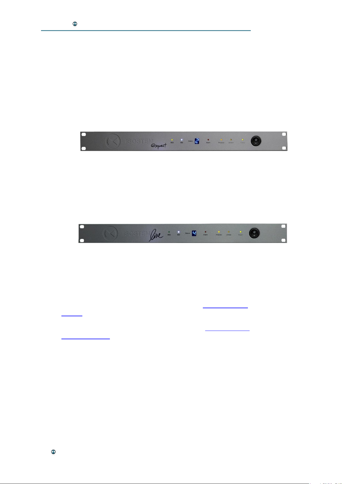
ISOSTEM®Expert contains a full range of functions and setting parame-
ters. Individual setups can be created using the ISOSTEM® GUI software
and saved as presets. Up to 6 presets can be stored locally in the hardware's memory, while the GUI also allows for unlimited preset storage on
your computer. In addition, presets can be transferred to any other ISO-
STEM®.
ISOSTEM®Live was created for daily broadcast use where creating indi-
vidual presets is not a relevant option. This version can use the factory presets as well as any other presets created on an ISOSTEM®Expert unit.
However, its limited GUI functionality does not allow for editing presets at
parameter level. ISOSTEM®Live also features a redundant backup function: If one of two connected devices fails, the system will switch to the other device automatically.
FRONT PANEL
The front panels of both ISOSTEM® variants feature the same set of status
LEDs:
· AES: This green LED shows the status of the incoming AES signal
as well as the unit's sync state. Please refer to the Synchronization
chapter for more details about the various sync states.
· ISO: Indicates that the "ISO" function is active (see Phase, ISO and
Master Functions)
· Status: This numerical display shows the number of the currently
active preset.
· Alarm: Shows the current health status of the hardware device.
· Process: Indicates processing or bypass mode.
· Linked: Indicates an active link to a second ISOSTEM® device
· Power: Indicates that the unit is switched on.
· Power Switch: Use this switch to turn the unit on or off.
14 Hardware
Page 15

ISOSTEM USER MANUAL
REAR PANEL CONNECTORS
IEC: Mains power 90..250 VAC
RS232 (D-Sub 9): Serial interface port for communication with
ISOSTEM®GUI software
GPI (D-Sub 15): This is a binary control input port used to recall the
six internally stored presets. External switch to
electrical ground initiates preset recall
WC In (BNC): Word clock input
AES/EBU I/O: 4x AES3 digital audio inputs (8 channels)
(D-Sub 25) 4x AES3 digital audio outputs (8 channels)
Tascam Pinout
ALARM (Phoenix): Relay output contacts reflecting the unit's alarm state.
Contacts closed: No alarm, device fully functional
(Alarm LED off).
Contacts open: Device failure (Alarm LED on)
or no power supplied
LINK (RJ45): Proprietary port for cross-connecting two ISOSTEM
®
LIVE units (backup operation)
For a technical description of the above hardware interfaces (pinouts, etc.),
please refer to Appendix A: Interface Specification.
Please note: For more details about system integration using the GPI,
Alarm and Link ports, please also refer to the Isostem Live - Integration
chapter.
Hardware 15
Page 16

ISOSTEM USER MANUAL
SYNCHRONIZATION
The ISOSTEM® hardware always uses a sample rate of 48 kHz. All Sync
parameters are set in the "Sync" section of the "Hardware" tab in the GUI
software (see "Hardware" Tab).
In order to suppress any risk of digital clicks, each AES channel has an
independent transceiver. In addition, all AES inputs are equipped with
sample rate converters (SRC). So, even when syncing to the internal clock,
the unit will accept external asynchronous AES signals. However, in order
to ensure that ISOSTEM®'s audio outputs are in sync with the studio environment, it might be advisable in most cases to use external synchronization.
The following sync sources are available:
· AES input recovered clock
· External Word Clock
· Internal 48 kHz clock
Please note: If the "AES 1 Input " option was selected as the primary clock
source (see Sync in "Hardware" tab chapter), ISOSTEM® will only look for
sync on its AES 1 input. In order to sync to an external AES signal, always
make sure you use the AES 1 input for this purpose.
The "AES" LED on the front panel will reflect the current sync status in the
following way:
Constant light: ISOSTEM® is in sync with the first clock source se-
lected in the "Master Clock Priority" parameter (see Sync in "Hardware" tab chapter)
Flashing once: ISOSTEM® is in sync with the second clock source
selected in the "Master Clock Priority" parameter (see Sync in
"Hardware" tab chapter)
Flashing twice: ISOSTEM® is synced by its internal clock.
Flashing continuously: No AES signal available at AES Input 1.
Configuration should be checked.
16 Hardware
Page 17
ISOSTEM USER MANUAL
GUI SOFTWARE REFERENCE
Depending on the hardware variant, the ISOSTEM®GUI software
is organized in two or three main windows accessed by tabs in
the top left corner. The "Hardware" tab is used for setting up clock
and synchronization parameters, firmware updates and system automation,
while the "Admin" tab window contains tools for preset management and
factory reset.
The "Expert" tab (only available in the ISOSTEM®Expert hardware version) features real-time control of all audio processing parameters.
"HARDWARE" TAB
COM
The Com section is used to establish communication between
the ISOSTEM®hardware unit and the GUI software.
Port Name
Use this option to select your computer's serial COM port for
communication. If using the supplied USB to RS232 adapter, its driver
software has to be installed first (see Software installation in the Quick Start
chapter) and you will have to select the COM port that your adapter emulates.
CONNECT (CONNECTED)
After having selected the COM port, press this button to establish communication. If the button changes to "CONNECTED", the communication between the GUI software and the ISOSTEM® hardware has been established
successfully and you should see a message like this in the topmost GUI
area:
If no connection has been established, try another COM port and press the
"CONNECT" button again.
DISCONNECT (DISCONNECTED)
Use this button to disconnect the hardware unit from the GUI software. After doing so, a dialog box will provide the option of writing the current configuration into the "Startup" register (The same dialog will pop up when
closing down the GUI software). Doing so ensures that
the system will load this configuration during the next
startup. This also includes the synchronization and automation settings.
GUI Software Reference 17
Page 18
ISOSTEM USER MANUAL
SYNC
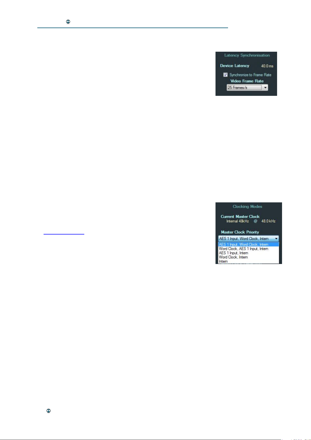
Latency Synchronization
The minimum audio processing latency is 40 ms. If working in audio
for video environments, it is recommended that you adjust the latency according to the video frame rate used.
Device Latency
This display shows the current audio processing latency.
Synchronize to Frame Rate
Check this box to increase latency to a value suitable for the video frame
rate set below. The increased latency will be reflected in the "Device Latency" display (see above).
Video Frame Rate
This parameter sets the video frame rate that the system latency should be
adapted to.
Options: 24, 25, 29.976, or 30 frames/s.
Clocking Modes
Use this section to set up the primary and secondary sync sources
to be used for system synchronization. For details, please also refer
to Synchronization in the Hardware chapter.
Current Master Clock
This display shows the clock reference currently used by the hardware and its sample rate.
Master Clock Priority
This parameter selects a priority chain of clock sources – i.e. a primary,
secondary and fallback clock source. If the attempt to synchronize to the
primary source is not successful, the unit will try to sync to the secondary
source instead. If this also fails it syncs to the internal clock as a fallback.
Options:
· AES 1 Input (1st), Word Clock (2nd), Intern (fallback)
· Word Clock (1st), AES 1 Input (2nd), Intern (fallback)
· AES 1 Input (1st), Intern (fallback)
· Word Clock (1st), Intern (fallback)
· Intern (fallback)
Please note: In order to sync to an external AES signal, select the appropriate clock source and make sure you use the AES 1 input for this purpose.
18 GUI Software Reference
Page 19
ISOSTEM USER MANUAL
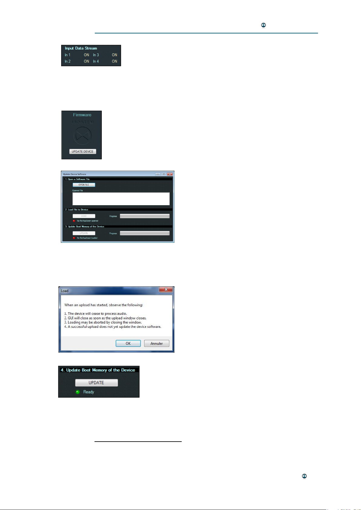
Input Data Stream
This display shows any valid audio data streams on the four AES
inputs.
FIRMWARE
UPDATE DEVICE
Use this option to update the system firmware. Please follow the steps
described below. After the installation of the GUI the firmware files are
located in the installation folder within the “firmware” subfolder.
After clicking the UPDATE DEVICE button, the
GUI asks if the presets, stored on the device,
should be saved onto disk. It is advisable to
save them because the update overwrites all
presets. After clicking on Yes, the destination
folder can be chosen in a dialog. After that the
"Update Device Software" window will lead
you through the update process consisting of
steps 1 – 3.
Step 1 - "Open a Software File": Click the "OPEN FILE" button to select the
“.iup”1 update file stored on your computer. The file path, name and size will
be displayed.
Step 3 - "Load File to Device": Click the
"LOAD" button to start transferring the file from
the GUI software to the hardware. Before
transfer, a dialog box shows some information
about the process details. Click “OK” to start
the transfer. The progression is shown by a
bar.
After the transfer is finished, the firmware update is ready
to be installed to the DSP. The "UPDATE" button is active.
1
In the firmware-subfolder the two iup-files „bundled_update.iup“ and „Isostem_Update_vXXXX.iup“ are located. Both store an identical content – therefore it
is irrelevant, which file you select. Both files are linked to the matching iub-firmware
files which suit your device variant.
GUI Software Reference 19
Page 20
ISOSTEM USER MANUAL
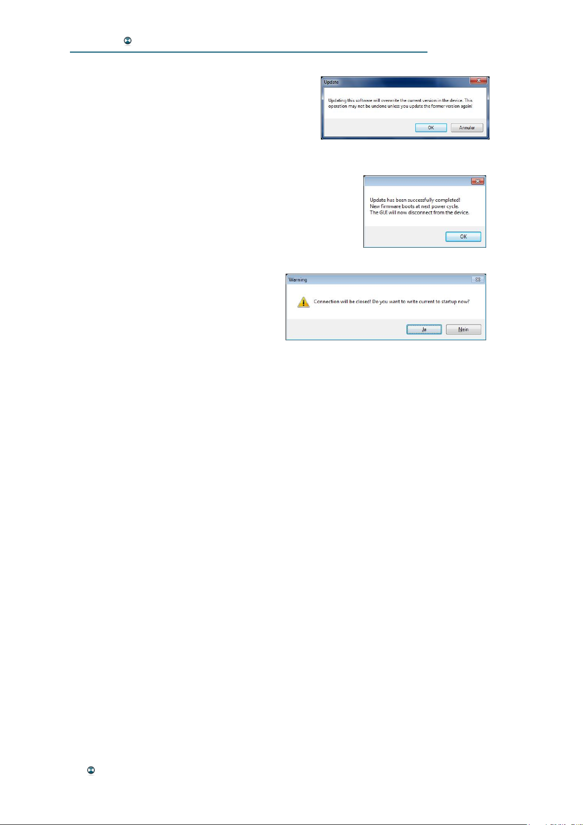
Step 3 - "Update Boot Memory of the Device”: The
boot memory of the device contains the DSP software. Click the "UPDATE" button that launches the
installation of the new internal DSP software. An
"Update" dialog box tells you that if you should
need to return to the previous version of the internal software, the corresponding “.iup” file will be necessary.
After finished, a dialog box signals the successful update
and informs that the new firmware will be active after the
next unit´s power cycle.
Before the GUI automatically disconnects from the device,
you have the possibility to store the current settings to the
start configuration of the unit.
20 GUI Software Reference
Page 21
ISOSTEM USER MANUAL
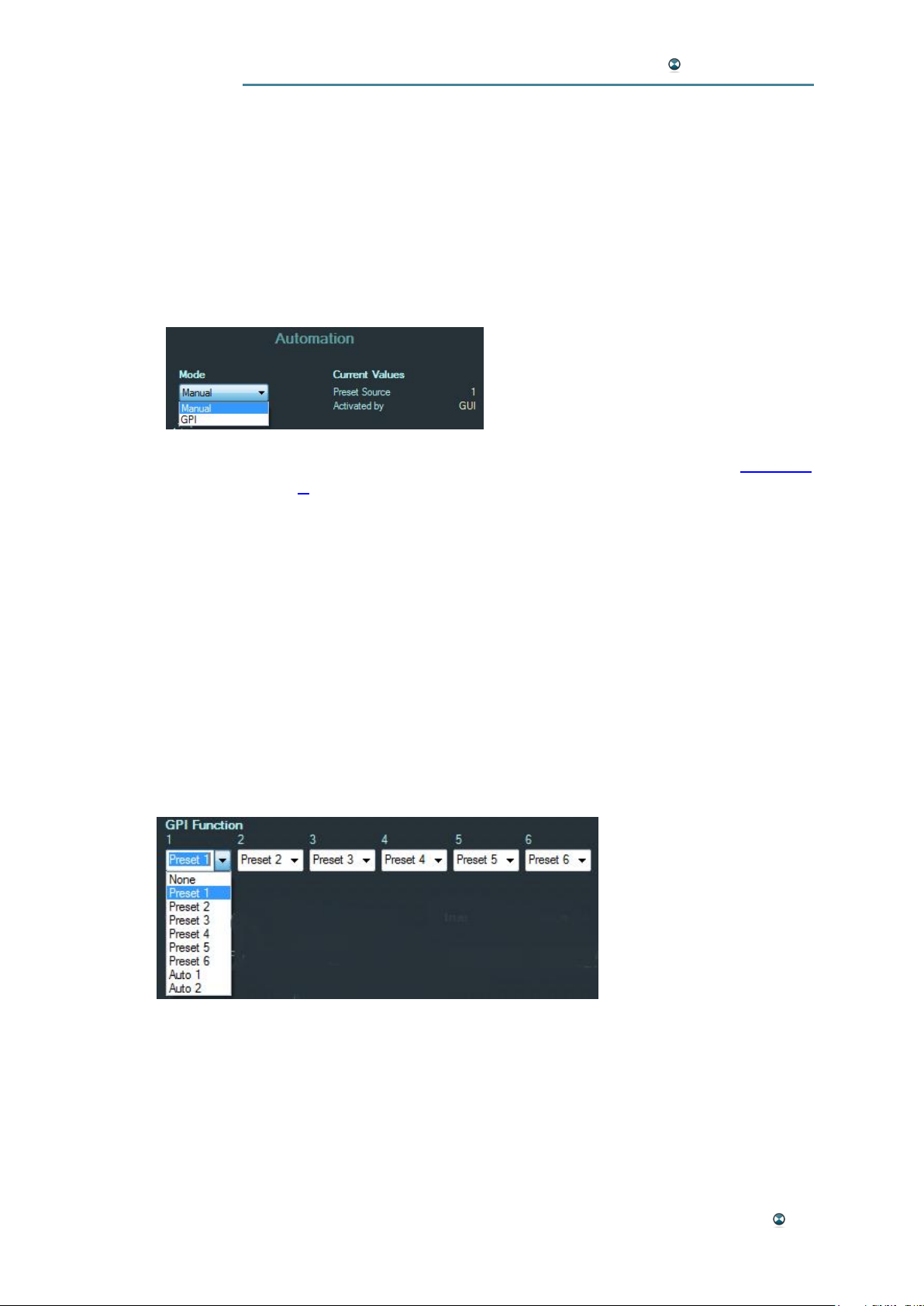
AUTOMATION
The "Automation" section offers several automated operating modes that
are selected with the "Mode", “GPI function” and “Channel Automation”
options. Among others, these options allow for locking the audio processing
parameters to fixed values, external preset switching and automated preset
switching triggered by the recognition of certain audio signal types.
Mode
The following mode options are available:
· “Manual”: The unit is responding
to the GUI software parameters in real
time. The “GPI function” is not available.
· “GPI”: The unit responds to exter-
nal GPI commands at the "GPI" Sub-D connector by loading one of
the 6 presets stored in its internal memory. Please refer to Appendix
A for the GPI connector's pin out scheme.
Please note: In GPI mode the “Admin” and “Expert” tabs are
locked. Additionally the “GPI”/”Manual” mode changes the behavior
of the startup configuration (see below “Admin” Tab).
Current Values
This is a status display showing in real-time during a connection to a device
the number of the current “Preset Source” and the source of activation
which may be the GUI or a GPI switch.
GPI Function
This function allows to configure the action which should take place after
the corresponding GPI pin has been activated.
For each of the six GPI inputs you may choose one out of following actions:
· None: No action to be invoked.
· Preset 1…6: The corresponding preset is called.
· Auto 1: Invoke “Parallel” channel automation (see below).
· Auto 2: Invoke “Serial” channel automation (see below).
Please note: To use these options the “Mode” has to be set to “GPI”.
GUI Software Reference 21
Page 22
ISOSTEM USER MANUAL
Parallel and Serial Channel Automation
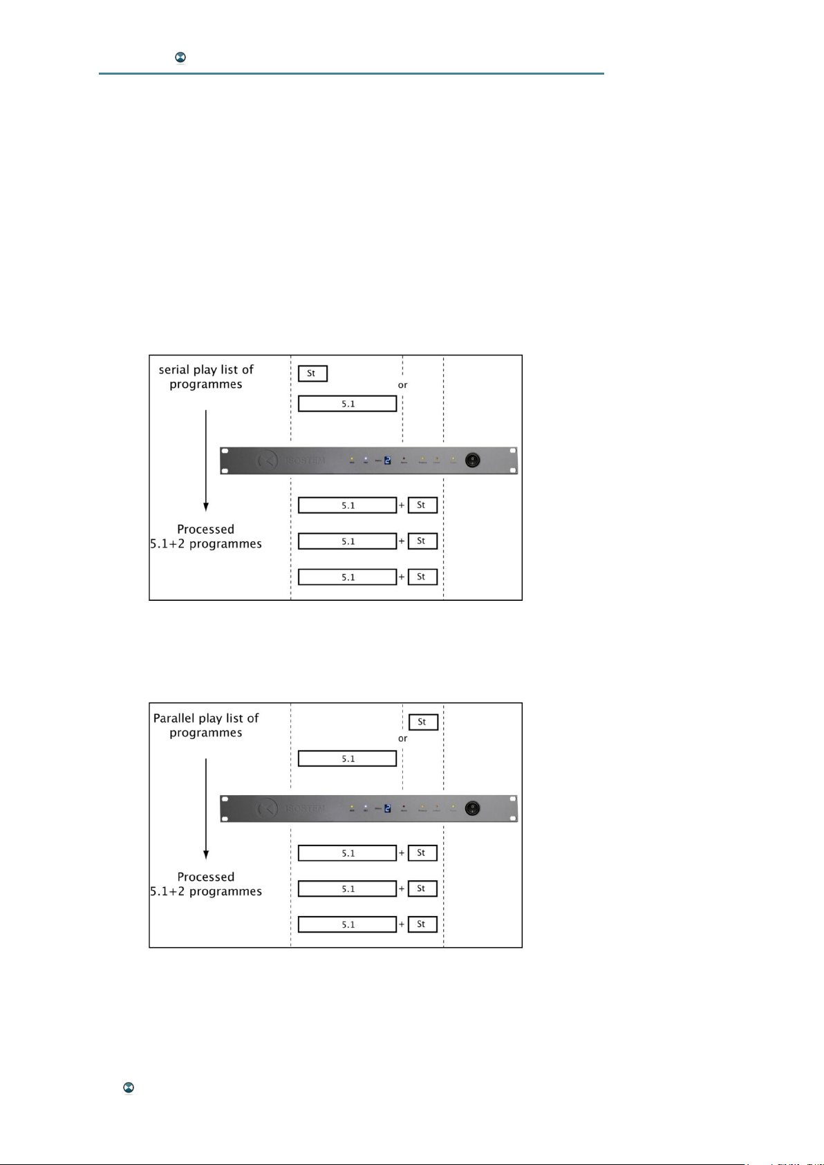
These two modes are dedicated to 5.1+2 broadcasting from various audio
program tracks. The idea behind it is to setup a system that will automatically respond to certain signal input configurations (5.1 or stereo) by selecting the appropriate presets. In this way, 5.1 signals may be processed to
5.1 + LtRt while stereo signals are transferred to 5.1 + LoRo stems.
The two available modes address two types of play lists that are presented
to the ISOSTEM® inputs:
· The "Serial" mode is used for a playlist containing stereo and 5 .1
tracks on the same channels.
· In contrast to this, the "Parallel" mode is used for a playlist containing stereo and 5.1 tracks on separate channels.
22 GUI Software Reference
Page 23
ISOSTEM USER MANUAL
The levels of channels specifically allocated to 5.1 are monitored by the system. If levels
pass a certain threshold value,
a new preset will be loaded
from the internal memory. The
transition between the presets
is performed smoothly using
crossfades.
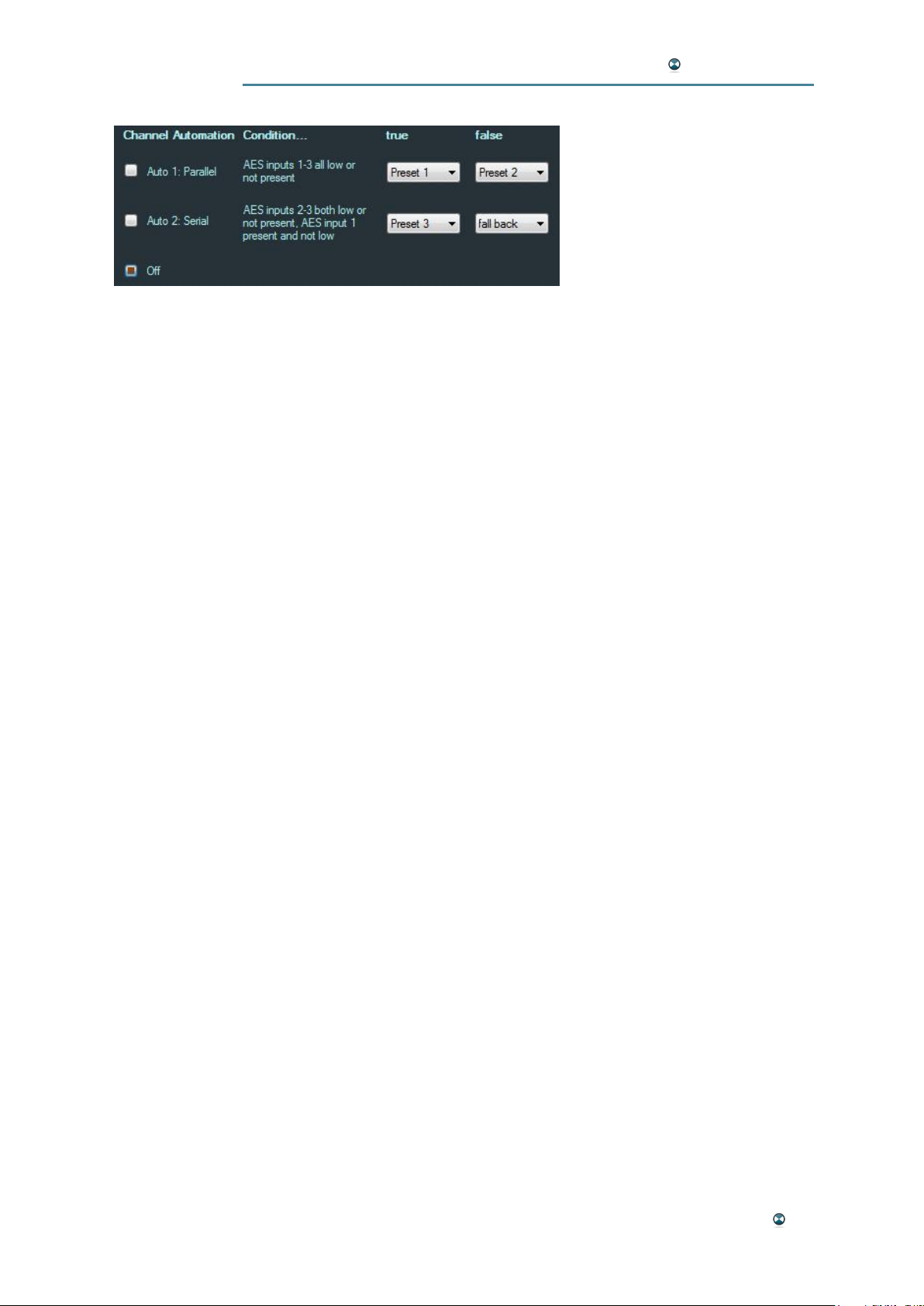
In “Parallel” mode (“Auto 1”), if the levels on channels L, R, C, LFE, LS and
RS on AES inputs 1, 2 and 3 are low, the condition becomes true, otherwise it becomes false.
In “Serial” mode (“Auto 2”), if the levels on channels C, LFE, LS and RS on
AES inputs 2 and 3 are low, the condition becomes true, otherwise it becomes false.
You configure the “Parallel” and “Serial” mode of channel automation by
activating the corresponding checkbox in the GUI. Checking “Off” disables
channel automation. The machine then monitors the corresponding channels as defined in the text below “Condition…” in the GUI and calls the corresponding preset defined in the “true” and “false” column.
“fall back” defines, that the device should re-enter the state it had before it
had entered another preset state within the channel automation handling.
Please note: The three checkboxes “Auto 1: Serial”, “Auto 2: Parallel” and
“Off” represent also the current status of the device when being connected
to the device. This is important to know, because the auto modes also may
be invoked by GPI calls when configured in “GPI” mode (see above).
GUI Software Reference 23
Page 24
ISOSTEM USER MANUAL
"ADMIN" TAB
The Admin tab is used for administration tasks such as loading and saving
presets in the hardware memory or on the computer's hard drive. These
tasks are performed in the upper section of the window.
The remaining window space is used for a detailed display that shows all
parameters of the currently loaded configuration at a glance.
READ/WRITE
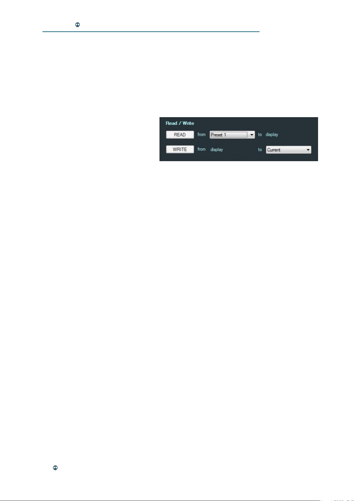
This preset management section is
used to load presets into the GUI
software and to write them to a target
such as the hardware's internal
memory or a file on the computer's
hard drive.
Loading a new preset to work with is a 2-step process: First, load a preset
to the GUI interface. Then, transmit this preset to the hardware.
To load a preset into the GUI software:
· Select a source in the field behind "from" in the first line. The following options are available:
Single Preset File – loads single preset from a file stored
on your computer
All Presets File – loads a preset file storing all six presets
from a file stored on your computer (for a
write action to “All Presets”)
Startup – loads the preset configured for system startup
Current – loads the configuration currently active in the
hardware
Preset 1-6 – loads one of the presets stored in the hardware
All Presets – loads all six presets stored in the hardware to
a file-buffer (for a write action to a “All Presets
File”)
· Press the READ button to load the selected preset source. The preset is loaded to the GUI now and all parameters are displayed in the
lower part of the Admin window.
Please note: When reading “All Presets File” or “All Presets” the
parameter display does not change, because these presets are
read to a hidden file-buffer.
24 GUI Software Reference
Page 25

ISOSTEM USER MANUAL
To write a configuration to a target:
· Select a target in the field behind "to" in the second line. The following options are available:
Single Preset File – save the displayed settings in a single
preset to a file on your computer
All Presets File – save all presets currently saved in the file buffer (after having read “All Presets”) to a
file on your computer
Startup – save the currently displayed configuration for
system startup
Current – transmit the currently displayed configuration to
the hardware, where it becomes active as a
volatile setting not stored in the preset memory
Preset 1-6 – save the currently displayed configuration to
one of the hardware presets slots
All Presets – save all presets currently saved in the file buffer (after having read a “All Presets File”) to
all hardware presets slots
· Press the "WRITE" button. The current GUI configuration is transferred to the selected target. The transfer is confirmed by a pop-up
window.
Please note: The automation mode (“GPI”/”Manual” – see above) changes
the behavior of the startup configuration. In “GPI” mode the “Startup” preset
is overwritten by the last called preset – i.e. the device starts with the formerly active preset after a power-cycle. In “Manual” mode the “Startup”
preset is not changed automatically. You can define it in the “Admin tab”
(see above).
GUI Software Reference 25
Page 26
ISOSTEM USER MANUAL
FILE BACKUP
Using the "File" selection to be the target of a write process, presets can
easily be transferred to a computer. The files created in this way carry the
"*.ips" extension. This is an easy way of archiving presets or transferring
them from one unit to the next.
Please note: Preset files do not contain hardware configuration settings
such as the latency synchronization or the preferred sync source. Such
parameters usually refer to the global system environment rather than specific audio processing tasks.
Loading a File
After selecting "File" in the "from" menu (first line), the standard file opening
dialog box of your computer's operation system lets you select an *.ips file
to be loaded into the GUI.
Please refer to Appendix C: Factory Presets for a brief overview of all facto-
ry presets integrated in the device. On the supplied ISOSTEM® installation
disc, these presets are also available as a backup.
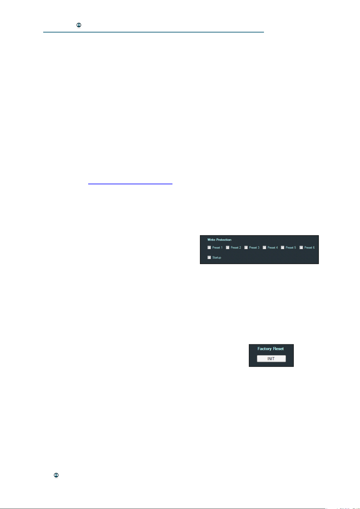
WRITE PROTECTION
This section is used to protect the six presets
stored in the hardware as well as the startup preset
from being overwritten. Just check the boxes of the
preset(s) you want to protect.
FACTORY RESET
This function is used to reset the hardware unit to factory defaults.
Please note: Doing so will erase all internal user-specific presets as well
as the unit's startup configuration and overwrite it with the factory defaults.
Press the "Init" button below "Factory Reset". If sure, confirm both
confirmation request windows. Your hardware will now use the factory default configuration.
26 GUI Software Reference
Page 27
ISOSTEM USER MANUAL
"EXPERT" TAB (EXPERT HARDWARE VERSION ONLY)
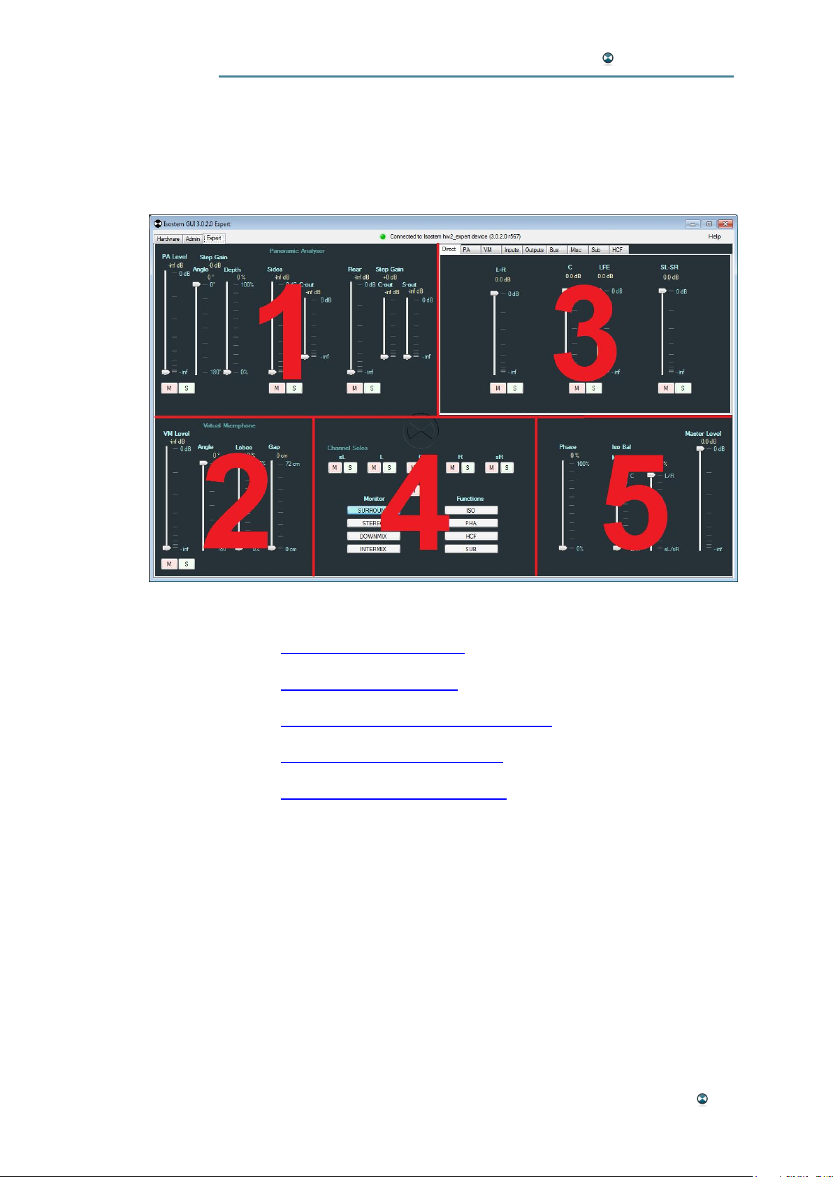
The Expert tab is used to edit the unit's audio processing parameters in real
time. All parameter settings on this page are directly reflected by the audio
processing.
The Expert tab is divided into five sections:
1 –"Panoramic Analyzer" (PA)
2 –"Virtual Microphone” (VM)
3 –Multifunctional area with 9 sub-windows
4 –Monitoring and Bypass functions
5 –Phase, ISO and Master functions
GUI Software Reference 27
Page 28
ISOSTEM USER MANUAL
PANORAMIC ANALYZER (PA)
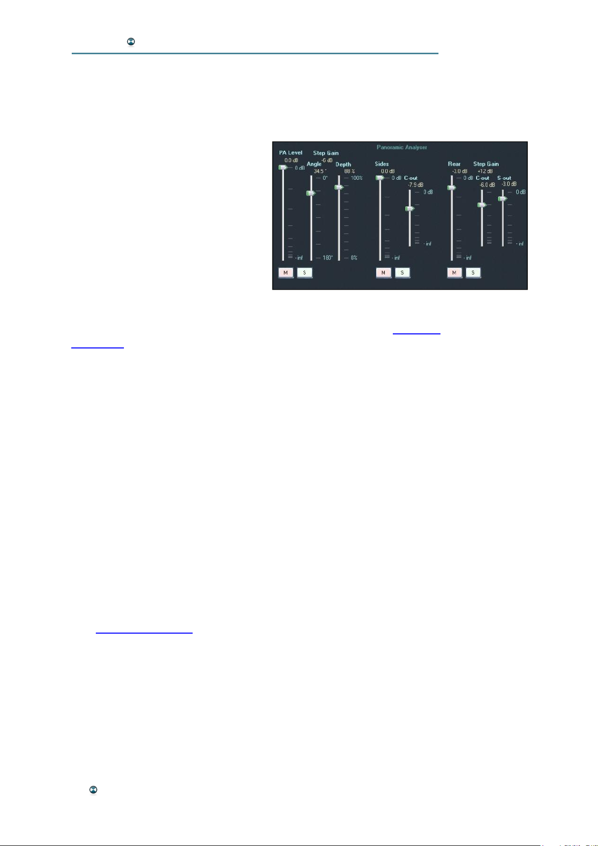
Functionality
The Panoramic Analyzer distinguishes the parts of a signal containing
mainly diffuse or direct sound by identifying the spatial energy distribution.
These signal elements are isolated by
dynamic filtering and can then be distributed to the surround channels following aesthetic considerations. It is
important to point out the fact that no
additional signal elements are created
by this process; in fact, the existing
elements are only distributed in a new
way.
Please note: While editing the Panoramic Analyzer's parameters, it is a
good idea to watch its graphic representation in the "PA" tab (see Multifunc-
tional Area).
PA Level
This fader adjusts the direct output levels for all six discrete output signals
of the Panoramic Analyzer (PA). However, it does not affect the signals
that the "Side level" and "Rear Level" faders contribute to the output busses.
Unit: dB
Range: 0 dB - -inf
Please note: On the "Bus" tab of the multifunctional area, the individual
levels of the L/R, C, Sub and sL/sR channels can be adjusted separately.
PA Level Mute/Solo
These buttons are used to mute or solo the Panoramic Analyzer's discrete
output signals.
Angle
This fader adjusts the opening angle of the stereo signal. Its position is reflected in the "PA" tab of the multifunctional area by two vertical grey lines
(see Multifunctional Area).
Unit: Degrees
Range: 0° - 180°
Depth
This fader controls the depth of the dynamic filtering performed by the Panoramic Analyzer.
Unit: Percent
Range: 100% - 0%
28 GUI Software Reference
Page 29

ISOSTEM USER MANUAL
Please note: Both Angle and Depth parameters are the crucial basis for
the Panoramic Analyzer's ability to separate direct and diffuse signal components from each other. They should be set carefully in order to fit the
source material and user's individual application in the best possible way.
PA Level Step Gain
This read-only display shows the Panoramic Analyzer's input attenuation
selected in the multifunctional area's "Misc" tab (see Multifunctional Area).
Unit: dB
Sides
This fader controls the level used to inject a mix of the stereo input signal
and the "Side C-out" level (see below) into the output busses L and R.
This parameter is a powerful tool to control the selectivity used to separate
direct and diffuse signal components in the L and R front channels. By subtracting the separated signals from the original stereo signal, the spatial
complements of the dry sources can be added to the L and R front channels.
Unit: dB
Range: 0 dB - -inf
Sides Mute/Solo
These buttons are used to mute or solo the Sides fader signal.
Sides C-out
This fader controls the level used to inject the phase-reverted discrete Center signal output of the Panoramic Analyzer into the output busses L and R.
This parameter is used to fine-tune the presence of the phantom source
between the L and R front channels. Higher fader positions increase the
removal of Center signal components from the L and R front channels.
Please note: This function depends on the position of the "Sides" fader
(see above). It is also controlled by the Sides Mute and Solo buttons.
Unit: dB
Range: 0 dB - -inf
Rear
This fader controls the level used to inject a mix of the stereo input signal,
the "Rear C-out" level and the "Rear S-out" level (see below) into the output
busses LS and RS.
This parameter is used to control the balance between direct and diffuse
signal components in the LS and RS rear channels. Higher fader positions
increase the spatial signal components.
Unit: dB
Range: 0 dB - -inf
GUI Software Reference 29
Page 30

ISOSTEM USER MANUAL
Rear Mute/Solo
These buttons are used to mute or solo the Rear fader signal.
Rear Step Gain
This read-only display shows the gain setting for the rear channels selected
in the multifunctional area's "Misc" tab (see Multifunctional Area).
Unit: dB
Rear C-out
This fader controls the level used to inject the phase-reverted discrete Center signal output of the Panoramic Analyzer into the output busses LS and
RS.
This parameter is used to fine-tune the presence of the phantom source
between the LS and RS rear channels. Higher fader positions increase the
removal of Center signal components from the LS and RS rear channels.
Please note: This function depends on the position of the "Rear" fader (see
above). It is also controlled by the Rear Mute and Solo buttons.
Unit: dB
Range: 0 dB - -inf
Rear S-out
This fader controls the level used to inject the phase-reverted discrete L
and R front signal outputs of the Panoramic Analyzer into the output busses
LS and RS.
This parameter is used to fine-tune the diffuse signal components of the
front channels L and R in relation to the direct sound in the LS and RS rear
channels.
Unit: dB
Range: 0 dB - -inf
Please note: This function depends on the position of the "Rear" fader (see
above). It is also controlled by the Rear Mute and Solo buttons.
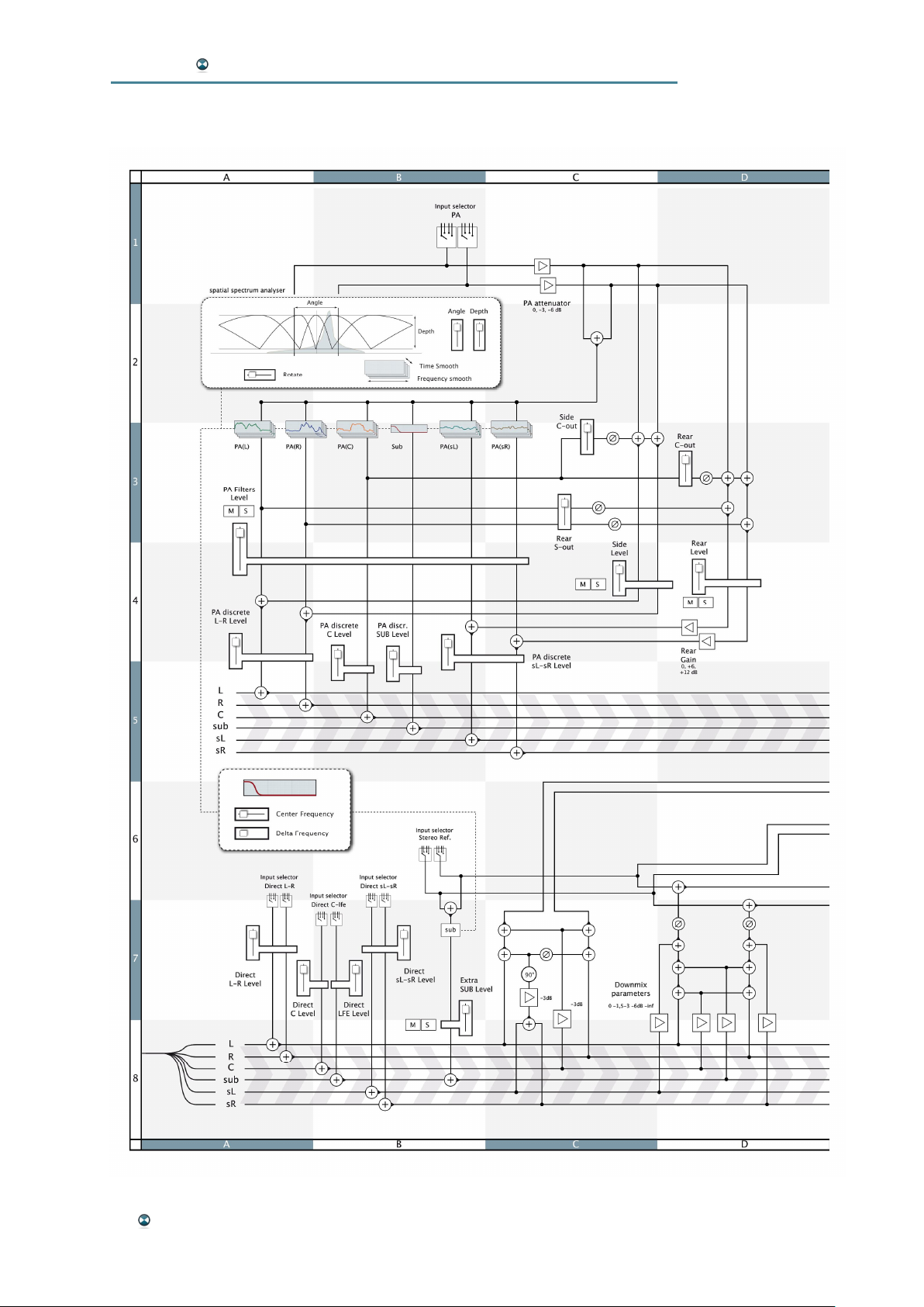
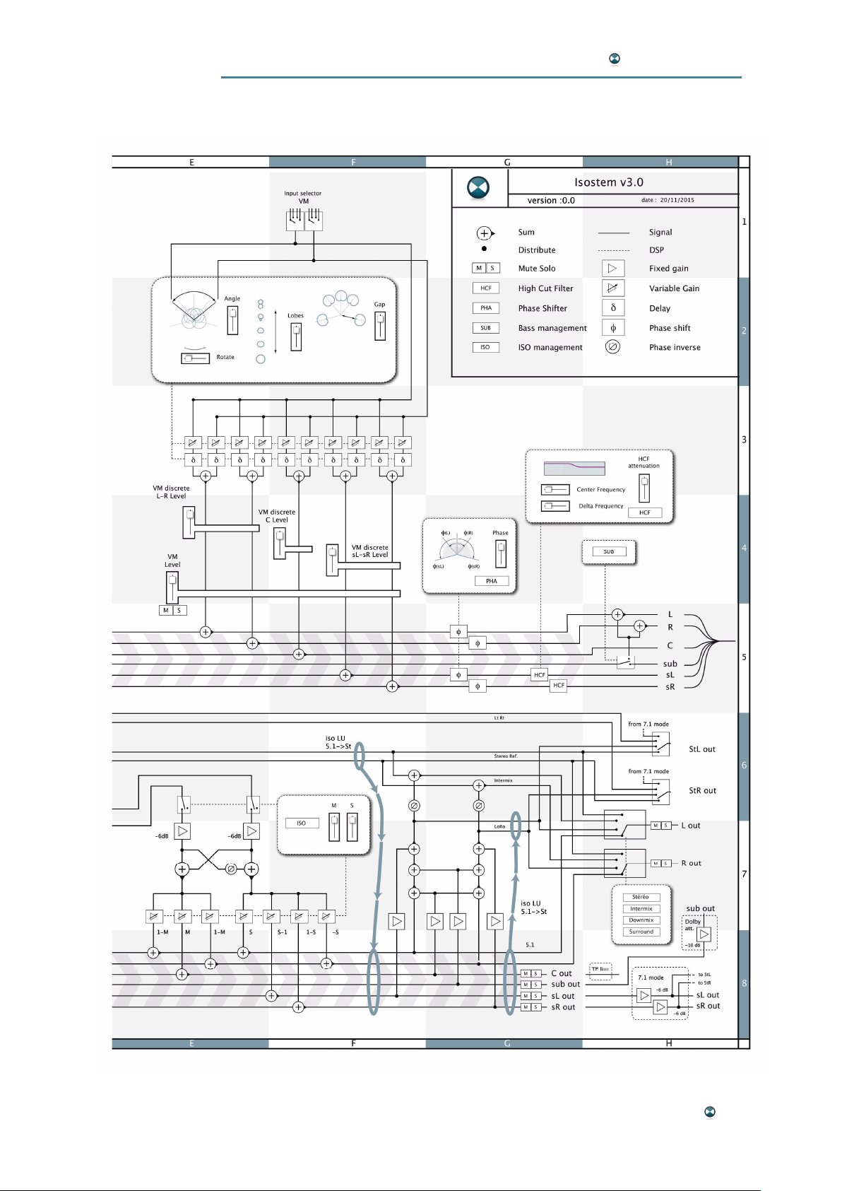
Please note: For in-depth signal flow details, please also refer to the block
diagram in Appendix B.
30 GUI Software Reference
Page 31
ISOSTEM USER MANUAL
VIRTUAL MICROPHONE (VM)
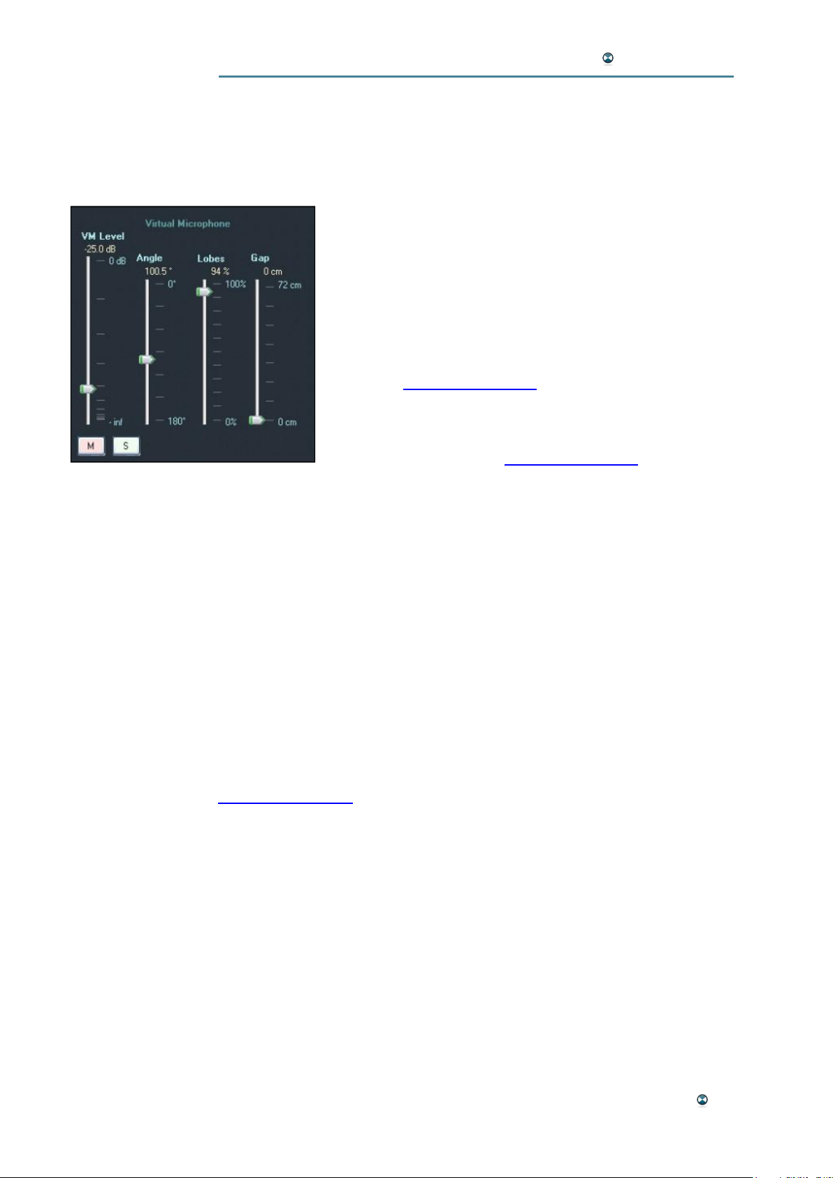
Functionality
The Virtual Microphone is another tool for surround sound creation that can
be used independently or in combination with the Panoramic Analyzer. Based on an acoustic model, the stereo source
information is translated to a virtual 5.0 microphone array –
you may think of it as if a 5.0 microphone setup would be
placed in front of a stereo speaker system. Cardioid microphone capsules are modeled with adjustable spacing and
directivity curves. The signals feed each of the output busses directly. The VM module does not deliver a Sub (LFE)
channel signal. It may be provided by the Sub module instead (see Multifunctional area).
Please note: While editing the Virtual Microphone's parameters, it is a good idea to watch its graphic representation in the "VM" tab of the multifunctional area.
VM Level
This fader adjusts the direct output levels for all five discrete output signals
of the Virtual Microphone (VM).
Unit: dB
Range: 0 dB - -inf
Please note: On the "Bus" tab of the multifunctional area, the individual
levels of the L/R, C, and sL/sR channels can be adjusted separately.
VM Mute/Solo
These buttons are used to mute or solo the VM fader signal.
Angle
This fader adjusts the opening angle of the stereo signal. Its position is reflected in the "VM" tab of the multifunctional area by two grey lines (see
Multifunctional Area).
Unit: Degrees
Range: 0° - 180°
Lobes
This parameter defines the polar pattern of all five virtual microphone capsules used in the VM module. A value of 0% represents omnidirectional
patterns, the maximum value 100% stands for figure-of-eights.
Unit: Percent
Range: 100% - 0%
GUI Software Reference 31
Page 32

ISOSTEM USER MANUAL
Gap
This parameter defines the center distance of all five virtual microphones.
Unit: cm
Range: 72 cm – 0 cm
32 GUI Software Reference
Page 33
ISOSTEM USER MANUAL
MULTIFUNCTIONAL AREA
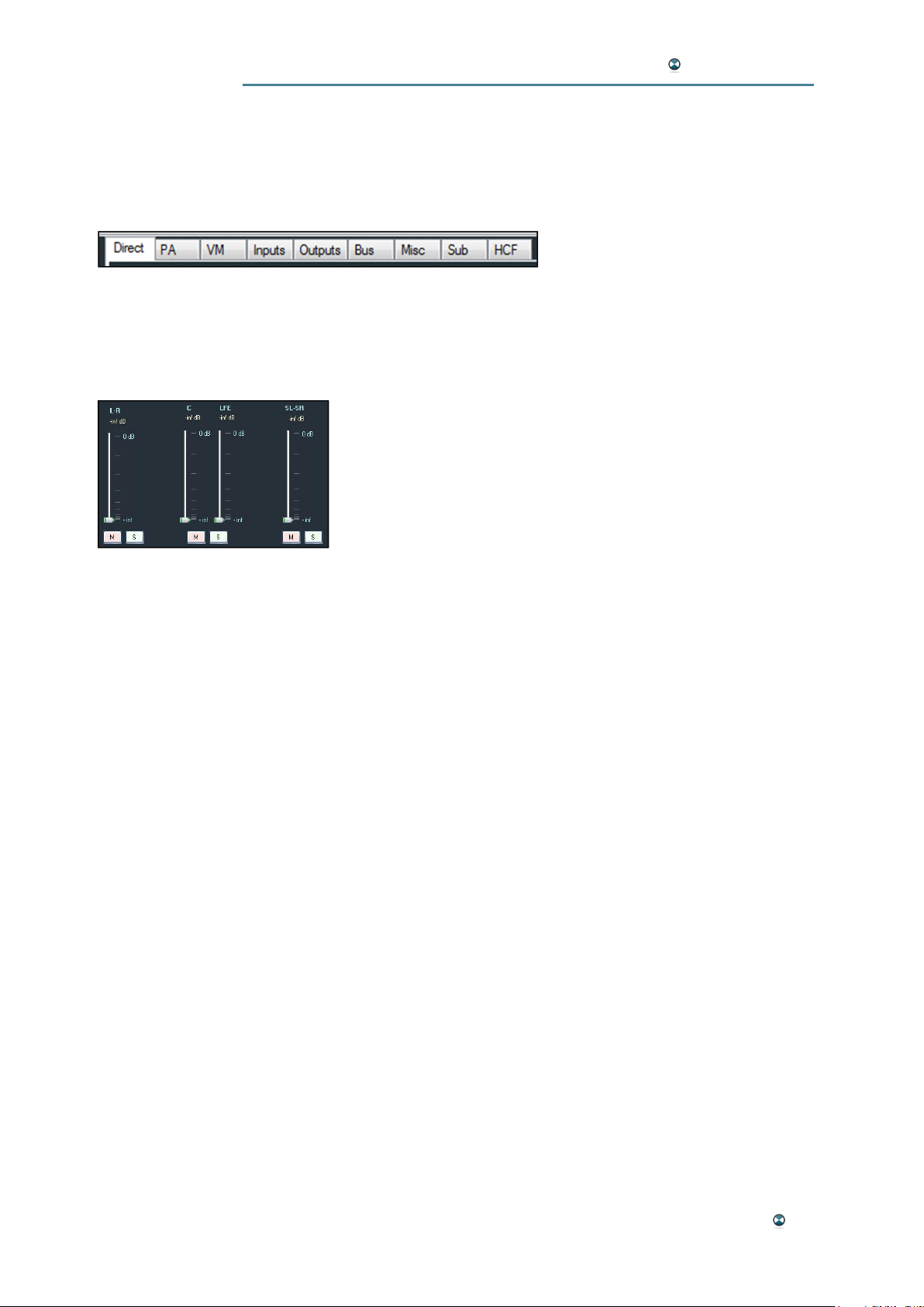
The multifunctional area in the top right-hand section of the Expert tab features nine view modes that are selected using sub-tabs. Among others,
they can be used to visualize parameter edits in audio processing modules
such as the Panoramic Analyzer
or the Virtual Microphone.
Direct Window
The direct module connects any multichannel sources present at the audio
inputs directly to the internal bus. This module is particularly important for
processing native multichannel programs.
L-R
This fader adjusts the direct level of the L and R front channels.
Unit: dB
Range: 0 dB - -inf
L-R Mute/Solo
These buttons are used to mute or solo the L-R fader signal.
C
This fader adjusts the direct level of the Center channel.
Unit: dB
Range: 0 dB - -inf
LFE
This fader adjusts the direct level of the LFE channel.
Unit: dB
Range: 0 dB - -inf
C/LFE Mute/Solo
These buttons are used to mute or solo the Center and LFE fader signals.
SL-SR
This fader adjusts the direct level of the SL and SR rear channels.
Unit: dB
Range: 0 dB - -inf
SL-SR Mute/Solo
These buttons are used to mute or solo the SL-SR fader signal.
GUI Software Reference 33
Page 34
ISOSTEM USER MANUAL
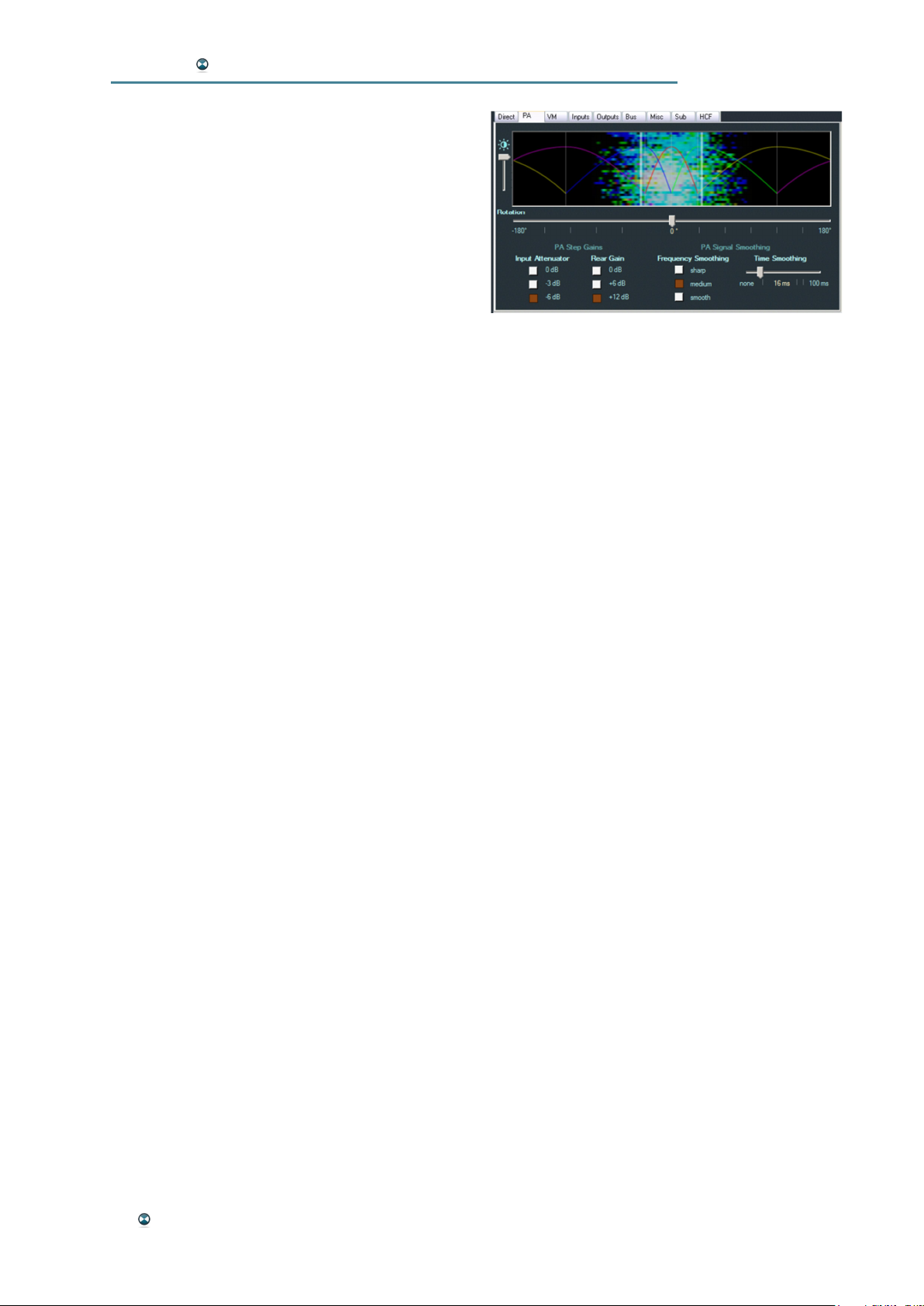
PA Window
The PA window features a visualization of the
Panoramic Analyzer's dynamic filtering with
overlapping filter bands. The angle set in the PA
parameter section is represented by two light
grey vertical lines. A vertical spectrogram of the
incoming stereo source is shown between these
lines.
Rotation
This parameter sets the axial rotation of the PA module. Among other
things, it can be helpful in order to correct an imbalanced stereo picture.
The effect of editing this parameter can be monitored in the visualization.
Unit: Degrees
Range: -180° / +180°
Brightness
This parameter sets the spectrogram's brightness.
PA Step Gains – Input Attenuator
The PA input attenuator avoids any risk of C channel saturation during an
up-conversion. If a stereo signal is made from an identical right-left signal
with its peak level normalized (0 dBFS), the total quantity of energy cannot
be held in only one C channel without overloading. The PA input attenuator
prevents this risk.
Options: 0 dB, -3 dB, -6 dB
PA Step Gains – Rear Gain
The gain on the rear PA channels applies to the "Rear" complement channels. This additional gain aims to reinforce the envelopment and to highlight
the presence of the multichannel format.
Options: 0 dB, +6 dB, +12 dB
PA Signal Smoothing – Frequency / Time Smoothing
The temporal and frequency smoothing apply to the spectral envelopes of
the PA module filters. The temporal smoothing is a weighted averaging of
the envelopes in time, while the frequency smoothing is a weighted averaging of the envelopes in frequency.
Frequency smoothing options : sharp, medium, smooth
Time smoothing options: none – 100 ms
34 GUI Software Reference
Page 35
ISOSTEM USER MANUAL
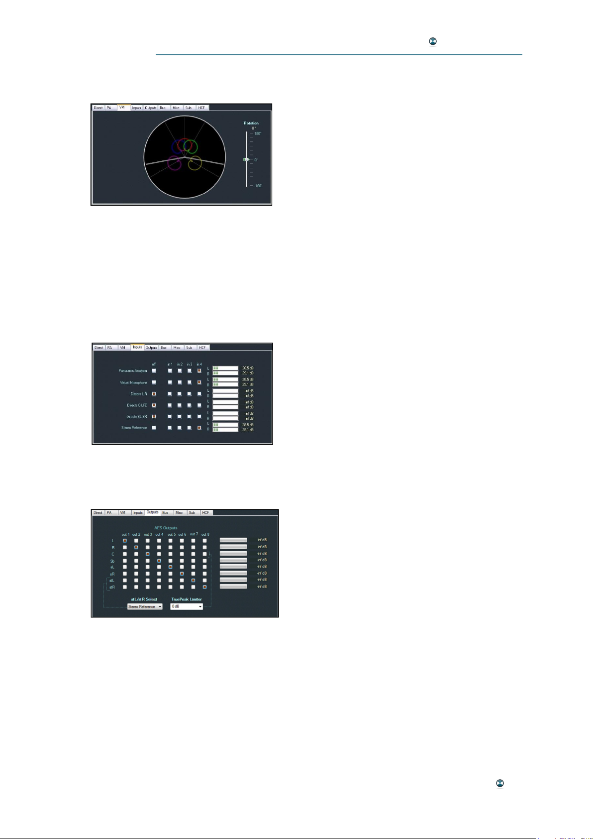
VM Window
The VM window features a graphic representation of the virtual 5.0 micro-
phone setup used by the VM module. The angle
set in the VM parameter section is represented
by two light grey lines; the form of the virtual microphones show the polar pattern set with the
"Lobes" parameter.
Rotation
This parameter sets the axial rotation of the VM module. Among other
things, it can be helpful in order to correct an imbalanced stereo picture.
The effect of editing this parameter can be monitored in the visualization.
Unit: Degrees
Range: -180° / +180°
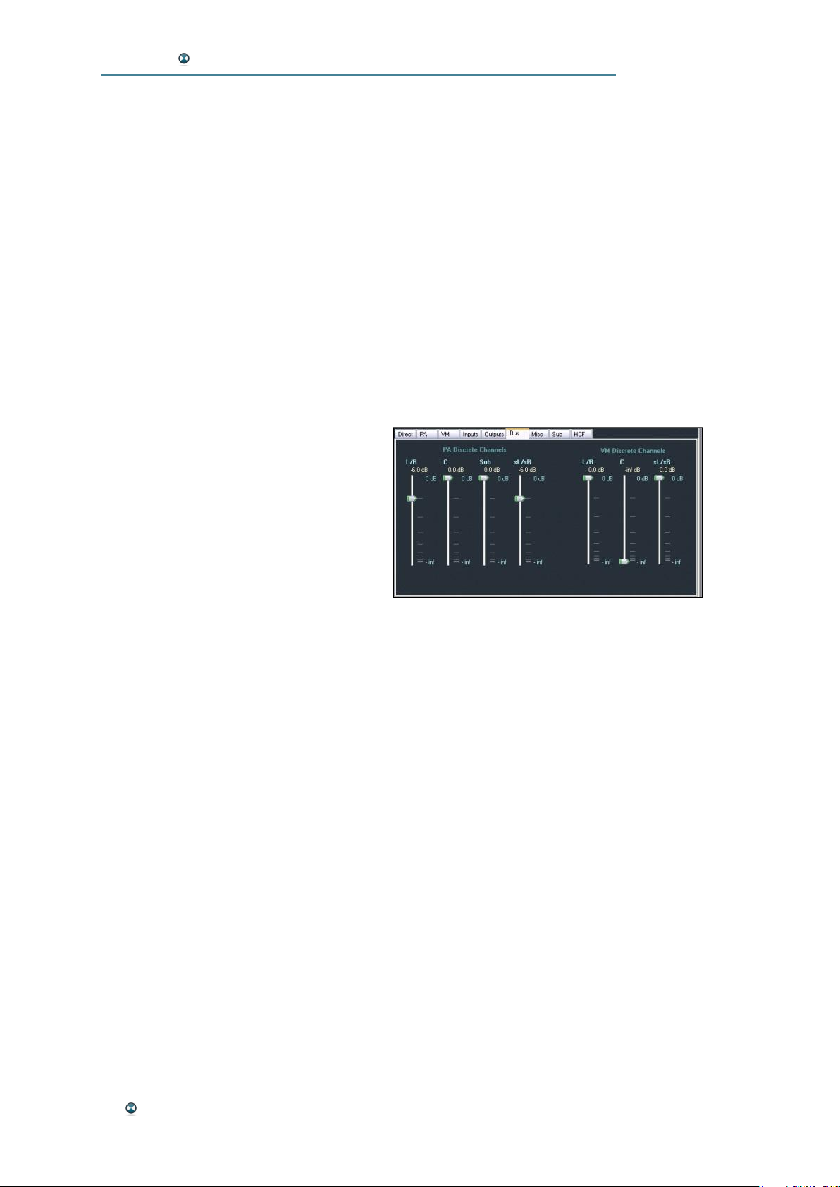
Inputs Window
The Inputs window features an input matrix covering all signal processing
modules and all four AES3 inputs. One of the
signal inputs can be assigned to each of the
modules. Also, horizontal bar graph level meters
are available for all module input channels.
Please note: L and R channels of each AES3
input are always switched in common.
Outputs Window
The Outputs window features a matrix covering all eight outputs of the in-
ternal bus system and all AES3 outputs. Each
physical output can be assigned to any one of
the bus outputs individually. However, it is not
possible to assign one bus output to more than
one physical output or vice versa. horizontal bar
graph level meters are available for all bus out-
put channels.
Please note: L and R channels of each AES3 output can be switched independently.
stL/stR Select
“sL/stR Select” defines the source of the “+2” in the “5.1 + 2” format. This
“+2” stereo output channels stL/stR alternatively may be Stereo Reference
Input, LtRt, LoRo or 7.1 (being a -6 dB version of Ls-Rs channels).
Options: Stereo Reference, 7.1, LtRt, LoRo
GUI Software Reference 35
Page 36
ISOSTEM USER MANUAL
Please note: The 7.1 mode does not correspond to the channel format of
the same name, which includes five front channels (L, R, C, CL and CR)
with two rear channels.
TruePeak Limiter
The function „TruePeak Limiter“ activates and configures a limiter at the
output of the center channel to avoid a signal overdrive, which may occur
on the center channel in extreme situations by the upmix. Internally the
TruePeak Limiter works with a 4 times oversampling to capture the true
signal amplitudes.
Options: off, 0dB, -1dB, -2dB, -3dB
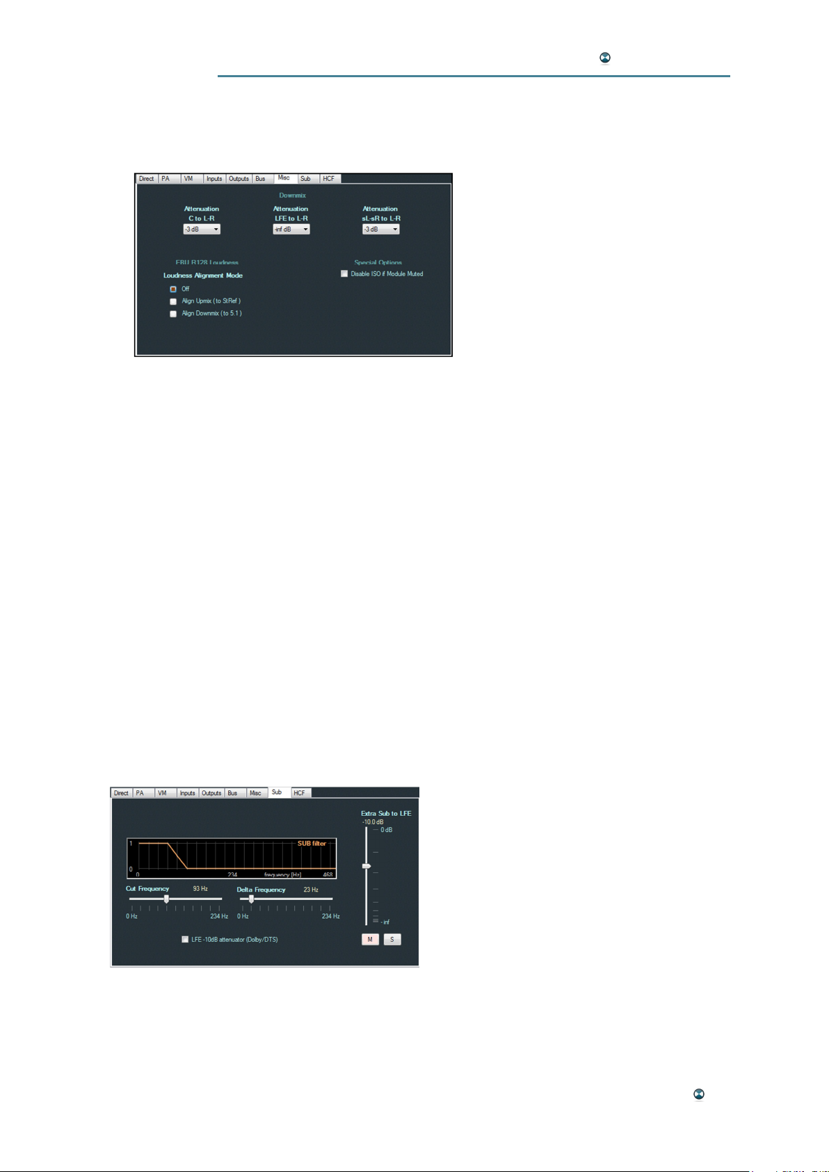
Bus Window
The Bus window features discrete channel faders for the outputs of the PA
and VM modules used for upmixing.
These level adjustments can be useful
to model the shape of a conversion: less
diverged (strong center), or more square
(quadrophonic).
Available faders for the PA module:
· L/R
· C
· Sub (LFE)
· sL/sR (RS/LS)
Available faders for the VM module:
· L/R
· C
· sL/sR (RS/LS)
36 GUI Software Reference
Page 37
ISOSTEM USER MANUAL
Misc Window
The Misc Window features several special signal processing functions such
as attenuation settings or signal smoothing options.
Downmix Attenuation – C to L-R,
LFE to L-R, sL-sR to L-R
The "Downmix" parameters for C, LFE
and sL-sR determine the coefficients
to be applied to the respective channels for the downmix to stereo.
Downmix attenuation options (all):
0 dB, -1,5 dB, -3 dB, -6 dB, -inf.
Loudness Alignment Mode
This function guarantees an identic EBU R.128 Programme Loudness of
the upmix and downmix results in relation to the source material.
Please note: After activation of this feature, the ISO function is minimally
limited in its effect, because the loudness alignment carries out a level correction at the end of the signal chain.
Options for Loudness Alignment: Off, Align Upmix (to StRef), Align
Downmix (to 5.1)
Disable ISO if Module Muted
The "Disable ISO" function deactivates the ISO function when "Mute" or
"Solo" has been selected in one of the modules. Mute and Solo do not work
efficiently as long as the intermix signal is reinjected into the multichannel
stem. Some users might get confused with "ISO" reinjection over an engaged Mute or Solo.
Sub Window
The Sub window features a Bass management option for Sub (LFE) chan-
nel filter adjustment. This filter acts on the
spectral envelope with a gain in amplitude
and constant phase. It applies to the Panoramic Analyzer module and the reference
stereo signal. Additionally a -10 dB LFE
Dolby/DTS attenuator is available.
Cut Frequency
Cut frequency of filter.
Unit: Hz
Range: 0 Hz .. 234 Hz in steps of 23 Hz
GUI Software Reference 37
Page 38
ISOSTEM USER MANUAL
Delta Frequency
Half width of the transition region.
Unit: Hz
Range: 0 Hz .. 234 Hz in steps of 23 Hz
LFE -10dB attenuator (Dolby/DTS)
Activates a 10 dB attenuation at the LFE output.
Extra Sub to LFE
The fader „Extra Sub to LFE“ controls the amount of additional bass, which
is extracted from the stereo reference signal and which is mixed to the LFE
channel of the output bus.
Unit: dB
Range: 0 dB..-inf
Please note: See Appendix B: Schematic Block Diagram.
Extra Sub to LFE Mute & Fade
Mute deactivates the extra bass. Solo mutes all other mute / solo controls.
This is useful to monitor the complete signal without the extra bass.
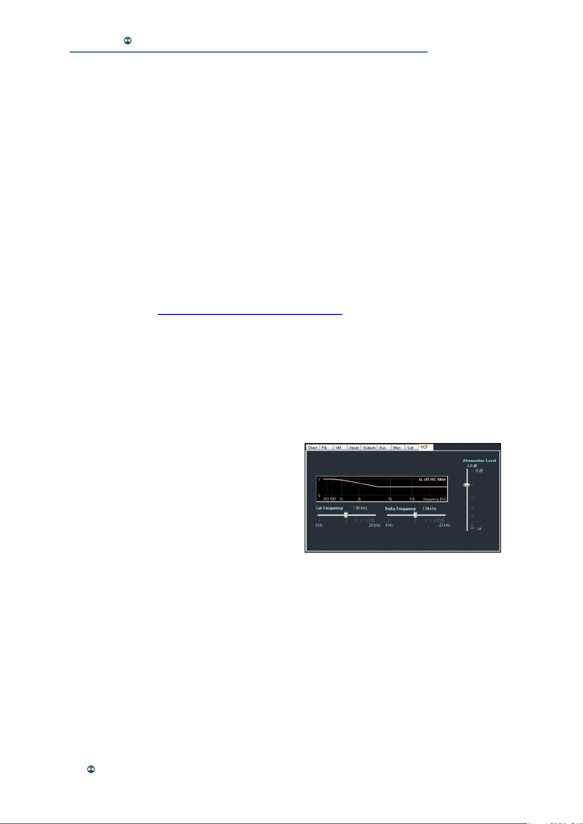
HCF Window
The HCF window features a high frequency attenuator on the rear channels
that allows the user to polarize the image and
reinforce the attraction of the front channels.
Just like "SUB", this filter acts on the spectral
envelope with a gain in amplitude and constant
phase. This filter applies to the internal bus at
the end of the Panoramic Analyzer and Virtual
Microphone.
Options: Cut Frequency (0 Hz – 20 kHz)
Delta Frequency (0 Hz – 20 kHz)
Attenuation level (0 dB - -inf)
38 GUI Software Reference
Page 39
ISOSTEM USER MANUAL
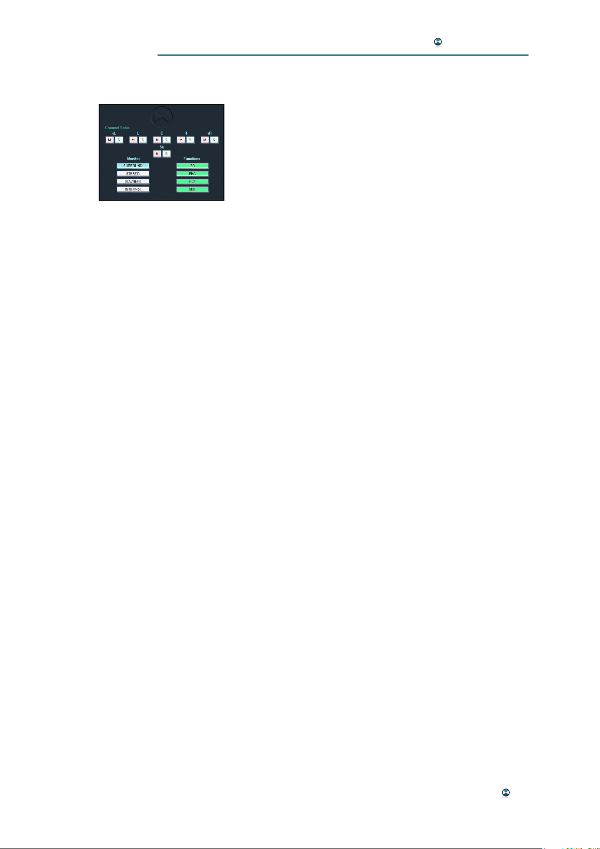
MONITORING AND BYPASS FUNCTIONS
This section features solo and mute buttons for each channel as well as a monitor source selector giving access to
various signals. Also, certain processing elements can be
bypassed with the "Functions" buttons. Please note that the
monitoring applies directly to the L, R, C, Sub, sL and sR
channels of the output matrix.
Channel Solos
Mute and solo buttons are available for each output channel.
Monitor – SURROUND
In SURROUND monitor mode, the ISOSTEM® surround outputs are monitored through the multichannel outputs.
Monitor – STEREO
In STEREO monitor mode, the original stereo input signal is monitored
through the multichannel outputs (L/R).
Monitor – DOWNMIX
In DOWNMIX monitor mode, the downmixed surround outputs are monitored through the multichannel outputs (L/R).
Monitor – INTERMIX
In INTERMIX monitor mode, the differential signal between the downmixed
surround outputs and the original stereo input signal is monitored through
the multichannel outputs (L/R).
Functions – ISO
The ISO button is used to toggle the ISO processing module between active and bypass mode. The ISO function can be activated to ensure that a
stereo downmix of the ISOSTEM®'s surround output signals is perfectly
compatible with the original stereo source. This is done by creating the difference signal between downmix and stereo signal. This "intermix" signal is
then injected into the surround model in a way that downmix and stereo
signal are identical. The ISO function can be easily disabled for applications
not enforcing perfect compatibility between the two. The ISO function uses
the downmix parameters which are configured in the Misc window.
Please note: An activated Loudness Alignment function guarantees an
identical Programme Loudness of the resulting downmix and the stereo.
Functions – PHA
The PHA button is used to toggle the PHA processing module between
active and bypass mode. For more details on the PHA module, please refer
to the following chapter.
GUI Software Reference 39
Page 40

ISOSTEM USER MANUAL
Functions – HCF
The HCF button is used to toggle the HCF processing module between
active and bypass mode. The HCF function is an attenuation of the high
frequencies applied to the rear channels on the internal bus at the output of
the PA and VM modules. The filter adjustment parameters can be found in
the "HCF" tab of the multifunctional area.
Functions – SUB
The SUB button is used to toggle the SUB processing module between
active and bypass mode. The SUB function treats the Sub (LFE) channel of
the internal bus at the output of the PA and VM modules. It determines the
multichannel signal format issued (5.0 or 5.1). When the "SUB" function is
activated, the Sub output channel is active. Otherwise, the Sub channel is
assigned to the L and R channels. The adjustment parameters can be
found in the "Sub" tab of the multifunctional area.
40 GUI Software Reference
Page 41

ISOSTEM USER MANUAL
PHASE, ISO AND MASTER FUNCTIONS
Phase
The "Phase" function shifts the phase of lateral and rear channels (L, R, sL
and sR) because up-converting introduces a negative tendency in L-R and
SL-sR correlation. This phenomenon is due to the fact that the correlated
part of the original stereo signal meets in the C channel.
The "Phase" function prevents this aspect by shifting the phase of the L-R
and sL- sR signals through only one variable. The variable is calibrated
from zero to one hundred percent and applies a phase shift modeled on the
physical angled distances of the loudspeakers.
Unit: Percent
Range: 100 % - 0 %
Iso Bal
The ISO balance function assures compatibility between the stereo and
multichannel formats. The difference between downmix and original stereo
signal is called "intermix". This intermix is inserted in the multichannel signal so that the downmix is mathematically identical to the stereo signal.
In order to be able to better integrate the intermix within the multichannel
stem, the ISO function separates the elements M (half sum) and S (half
difference) of the "Intermix". Element M is split between channels C and LR. Element S is split between the L-R pair and the SL-SR pair.
M
Unit: Percent
Range: Center – L/R
S
Unit: Percent
Range: L/R – sL/sR
Master Level
This fader is used to attenuate the master output level of all channels.
Unit: dB
Range: 0 dB - -inf
GUI Software Reference 41
Page 42

ISOSTEM USER MANUAL
ISOSTEM®LIVE - INTEGRATION
SCOPE
ISOSTEM® Live is intended for integration into professional studio and
broadcast environments in three different ways:
· Single device
· Two daisy-chained devices
· Two devices in parallel
In single device operation, no functional redundancy is given. In case of a
failure, each ISOSTEM® Live has the means for non-disruptive quadruple
AES3 bypassing, though, of course, it will no longer be able to process the
audio streams.
Two devices may be integrated daisy-chained or in parallel. Both setups
offer functional redundancy. Though a daisy-chained integration has no
need for further failure management devices, it offers no non-disruptive
device exchange in case of a required service procedure.
For 24/7-operation, a parallel ISOSTEM® Live integration is recommended.
Failed devices may be exchanged non-disruptively. This setup requires an
external AES3 audio routing device.
This section enables users to integrate ISOSTEM® Live into studio and
broadcast systems in each way mentioned above. In addition, information
for preset and parameter synchronization in a redundant setup is given.
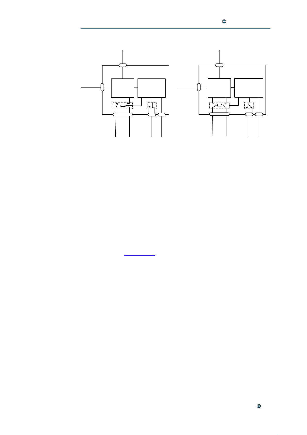
SINGLE DEVICE AUDIO ROUTING AND ALARM FUNCTION
ISOSTEM® Live is equipped with an internal hard-wired supervisor which
detects hardware, software and power supply failures. A detected failure
results in the following immediate action:
· The audio routing is switched from processing to bypass, i.e. the
four AES-Input signals are electrically switched to the four AESoutputs without DSP interference. This is the default power-off state.
· The alarm relay output opens its contacts to signal the failure electrically. This is the default power-off state.
42 ISOSTEM® Live - Integration
Page 43
ISOSTEM USER MANUAL
Single device setup and alarm/processing interaction:
DSP
4 x AES-IN
RS-232
ISOSTEM
Super-
visor
LINK
4 x AES-OUT
ALARM
RS-232
ISOSTEM
6 x GPI-
PRESET
OK status - no alarm (contacts closed)
Processing: AES-In → DSP → AES-Out
DSP
4 x AES-IN
4 x AES-OUT
Super-
visor
6 x GPI-
PRESET
LINK
ALARM
FAILURE status – alarm active (contacts open)
No Processing = Bypass: AES-In → AES-Out
In a single device setup, the link port is unused.
DAISY-CHAINED AUDIO ROUTING AND SYSTEM STATES
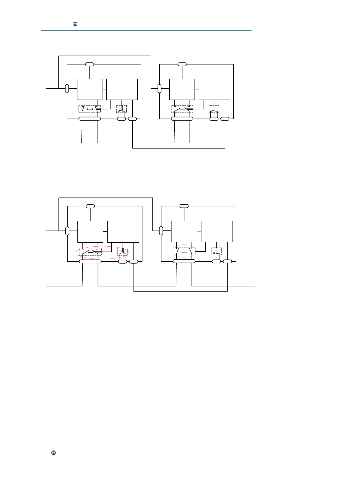
Two ISOSTEM® Live are intended to operate as a redundant backup system. A daisy-chained topology is the basic redundant setup (see schematic
below).
It must be noted that the daisy-chained setup may not apply to systems
intended to operate 24 hours and 7 days a week. This is due to the fact
that, in cases of failure, the audio chain is disconnected while exchanging
the failed device. 24/7-systems are handled by a parallel ISOSTEM® Live
audio setup (see next chapter).
The four AES-In signals from the audio uplink are wired to ISOSTEM® #1,
its four AES-Out signals are wired to the next ISOSTEM® (#2) and its four
AES-Out signals are wired to the system´s downlink device.
A CAT5-crosslink interconnection of the two link ports is required for proper
audio routing. If connected to both link ports, each ISOSTEM® ´s supervisor
handles this as a linked-condition.
Thus one of the two devices is forced to the processing state and the other
to the bypass state. The bypassing ISOSTEM® is the backup device.
The user defines the initial processing-bypass state of both devices during
power-up. When linked, the device powered up as the first is automatically
the one in processing state. The second device power-up is automatically
forced to bypass audio.
ISOSTEM® Live - Integration 43
Page 44
ISOSTEM USER MANUAL
Daisy-Chained Setup:
ISOSTEM#1
6 x GPI-
PRESET
DSP
4 x AES-IN
Example: ISOSTEM #1 processes, ISOSTEM #2 bypasses, no alarm
Super-
visor
LINK
4 x AES-OUT
ISOSTEM#2
DSP
4 x AES-IN
4 x AES-OUT
Super-
visor
LINK
The alarm state overrides this situation: An alarm always forces the bypass
state. The block diagram below presents an example of an alarm situation
for ISOSTEM® #1.
ISOSTEM#2
DSP
Super-
visor
6 x GPI-
PRESET
ISOSTEM#1
DSP
Super-
visor
4 x AES-IN
4 x AES-OUT
Example showing ISOSTEM #1 in alarm state
(ISOSTEM #1 bypasses, ISOSTEM #2 processes)
LINK
4 x AES-IN
4 x AES-OUT
LINK
All possible situations in linked mode are:
No alarm: One device processes (in our example ISOSTEM® #1), the other
is the backup – it bypasses audio.
ISOSTEM® #1 with alarm, ISOSTEM® #2 no alarm: The backup ISO-
STEM® #2 takes over and processes, whereas ISOSTEM® #1 bypasses
and signals its failure state by LED and alarm relay.
ISOSTEM® #2 with alarm (the backup device), ISOSTEM® #1 no alarm:
The backup-device ISOSTEM® #2 cannot provide backup any more but of
course stays in bypass. It signals its failure state by LED and alarm relay.
ISOSTEM® #1 and ISOSTEM® #2 with alarm: Both devices are forced to
bypass audio – i.e. the audio chain is not disconnected, but no ISOprocessing is made. Both devices signal their failure state by LED and
alarm relay.
44 ISOSTEM® Live - Integration
Page 45
ISOSTEM USER MANUAL
®
PARALLEL SETUP FOR 24/7-OPERATION
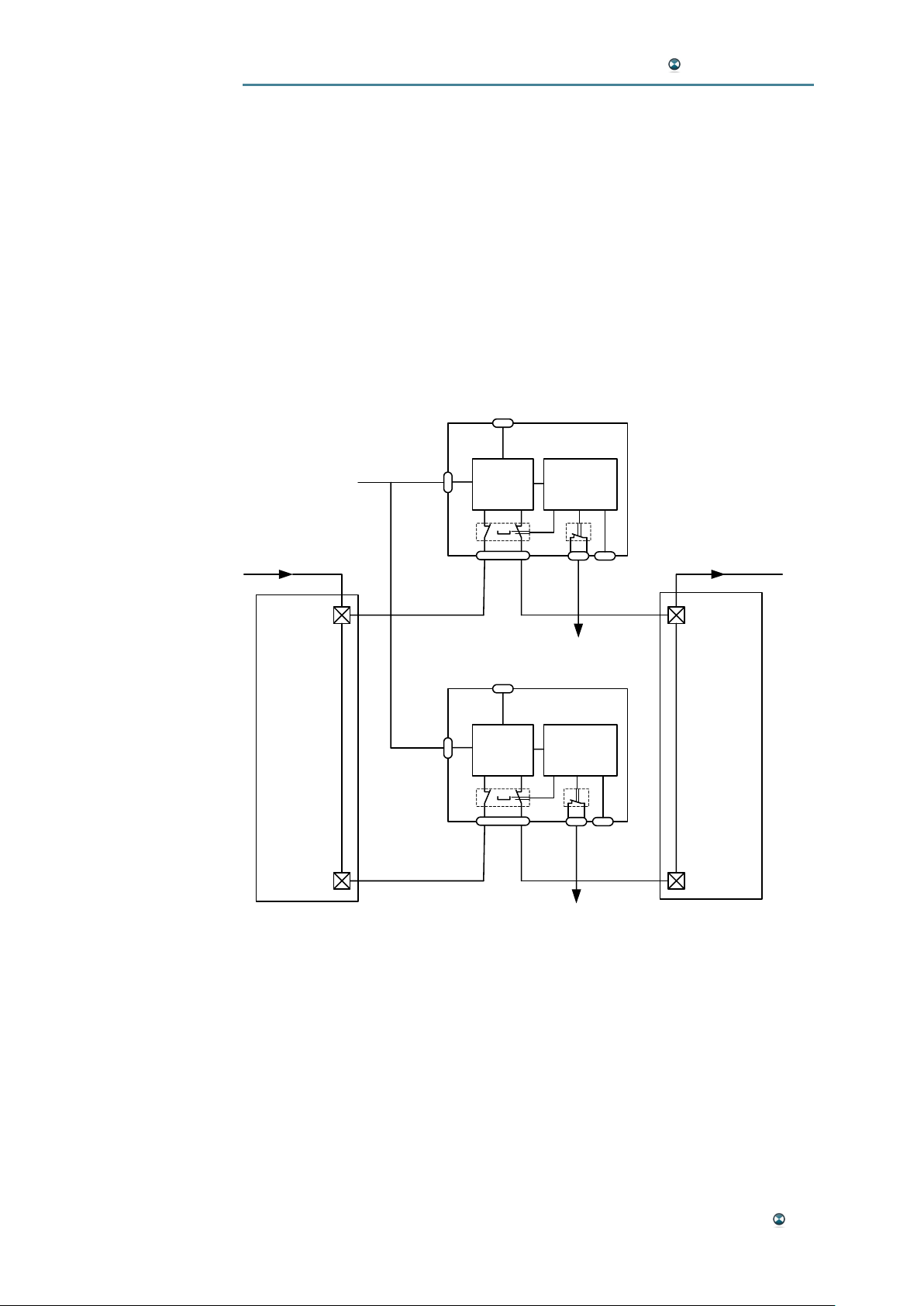
The diagram shown below presents the parallel audio setup of an ISO-
STEM® Live pair. An external audio matrix with following capability is re-
quired:
- Two quadruple AES-input cross points (CPI-1, CPI-2),
- two quadruple AES-output cross points (CPO-1, CPO-2), and
- two binary control inputs handling the alarm outputs of the ISOSTEM
devices with the ability of conditional processing to control the AEScrosspoints (CPI-1/2 and CPO-1/2).
ISOSTEM#1
6 x GPIPRESET
DSP
Super-
visor
4 x AES-IN
CPI-1
4 x AES-IN
4 x AES-OUT
ALARM#1
4 x AES-OUT
CPO-1
ISOSTEM#2
Input-
Matrix
CPI-2
Parallel audio and alarm setup of an ISOSTEM Live pair for 24/7-operation
6 x GPIPRESET
DSP
4 x AES-IN
Super-
visor
4 x AES-OUT
ALARM#2
Output-
Matrix
CPO-2
For proper parallel operation, the link interconnection is not mandatory.
Basically, both devices run as single devices.
The external audio matrix has to process the devices´ alarm relay states
(ALARM#1, ALARM#2) and has to ensure that in all situations, the AES
inputs and AES outputs of each device are separated electrically.
ISOSTEM® Live - Integration 45
Page 46
ISOSTEM USER MANUAL
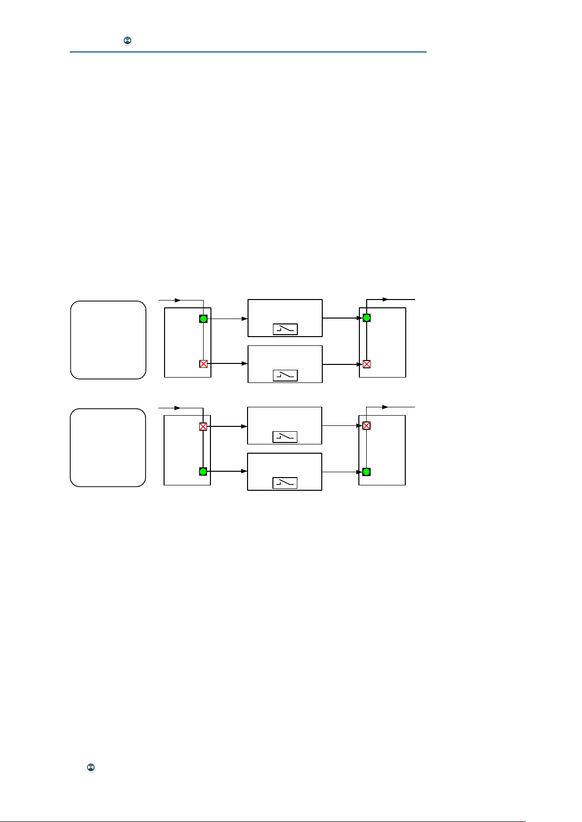
The schematic diagram shown below presents an example of the matrix´s
conditional processing by merely handling the alarm relay output of ISO-
STEM® #1:
If ALARM#1 (independently of the alarm state of ISOSTEM® #2) represents a fully functional state, the audio matrix routes the AES data only to
ISOSTEM® #1.
If ALARM#1 represents a failure, switch-over to the backup ISOSTEM® #2
is effected. ISOSTEM® #1 may now be exchanged without interrupting the
audio line. It must be noted that, after exchanging the formerly failed ISO-
STEM® #1, the audio matrix will switch back to ISOSTEM® #1 because it
will signal ALARM#1 = OK.
In this example, in the case that both devices fail, ISOSTEM® #2 receives
the audio data. But as it has a failure, it just bypasses the AES-data from
input to output.
4 x AES-IN
IF
(ALARM#1 = OK)
THEN
Switch-on In-/OutCrosspoint to ISOSTEM#1.
Switch-off In-/OutCrosspoint for ISOSTEM#2.
IF
(ALARM#1 = ERROR)
THEN
Switch-off In-/OutCrosspoint to ISOSTEM#1.
Switch-on In-/OutCrosspoint for ISOSTEM#2.
Example of conditional processing for proper audio routing
CPI-1
Input-
Matrix
CPI-2
4 x AES-IN
CPI-1
Input-
Matrix
CPI-2
ISOSTEM#1
ISOSTEM#2
ISOSTEM#1
ISOSTEM#2
ALARM#1
ALARM#2
ALARM#1
ALARM#2
4 x AES-OUT
CPO-1
Output-
Matrix
CPO-2
4 x AES-OUT
CPO-1
Output-
Matrix
CPO-2
PRESET RECALL SYNCHRONIZATION
In linked redundant mode, both GPI ports have to be interconnected in parallel as shown in the schematic diagram above. Thus preset recall actions
are processed by both devices synchronously. This ensures that the backup device always runs in the same mode as the current processing device.
PRESET MANAGEMENT SYNCHRONIZATION
ISOSTEM® Live´s PC-based graphic user interface (GUI) allows for man-
agement of the six preset memories. Presets can be read from the PC and
stored in the device´s preset memory.
In redundant setups, the user has to synchronize the preset content and
memory assignment manually. Future GUI and firmware revisions will offer
automatic synchronization of parameters and preset memories via the link
port.
46 ISOSTEM® Live - Integration
Page 47
ISOSTEM USER MANUAL
APPENDIX
APPENDIX A: INTERFACE SPECIFICATION
GPI PORT
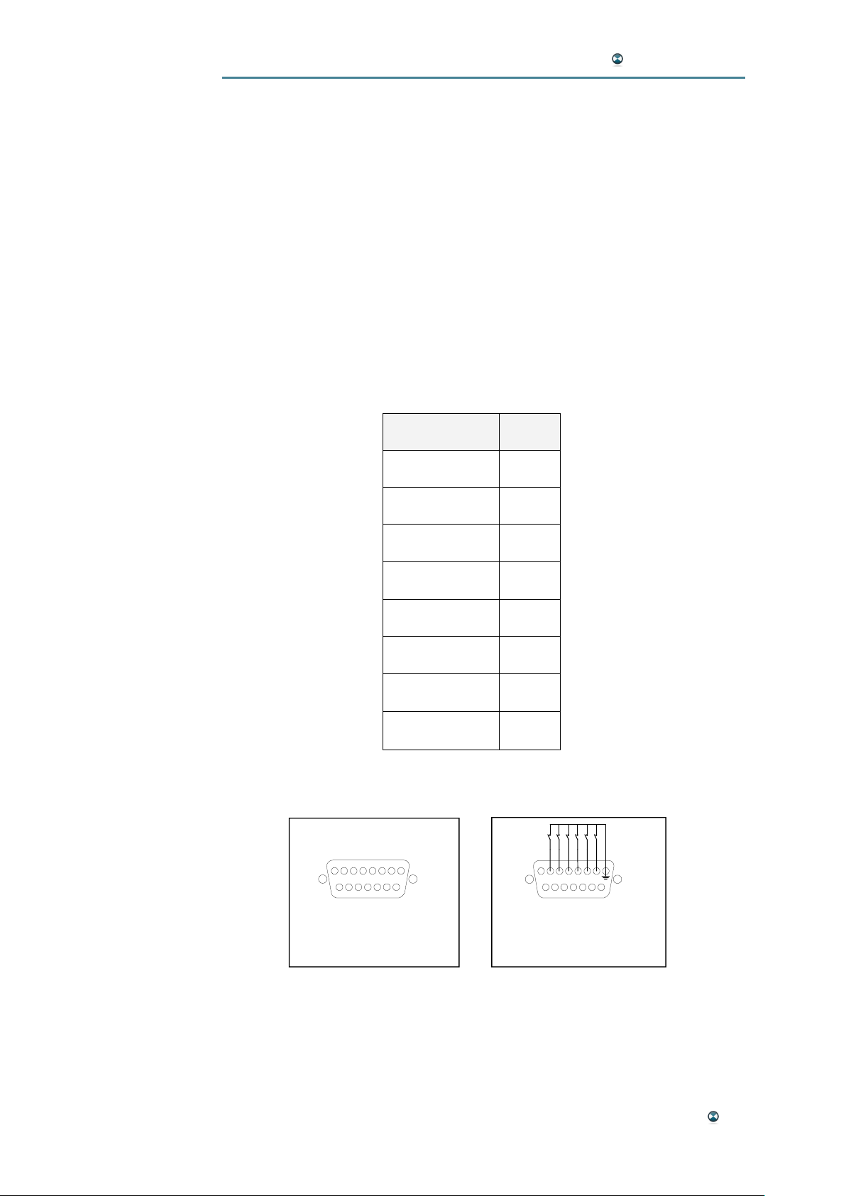
The GPI port of ISOSTEM®features an easy way to recall six parameter
presets remotely. A preset is triggered by pulling the dedicated preset pin to
the device´s electrical ground (GND). The GPI inputs are level-sensed.
Thus, a momentary push-button has to be pressed (to close its contacts)
for a very brief period of time (<1sec.).
The preset is called during state transition from open to closed, i.e. GND.
Thus, a momentary push-button switch is capable of calling a preset.
Function Pin#
Call Preset #1 7
Call Preset #2 6
Call Preset #3 5
Call Preset #4 4
Call Preset #5 3
Call Preset #6 2
GND 1, 8, 9
reserved 10..15
Pin and function assignment of GPI port
12345678
9101112131415
View of female SUB-D 15-pin
GPI interface on rear side
Schematic diagram of pushbutton connection
Appendix 47
Page 48
ISOSTEM USER MANUAL
LINK PORT
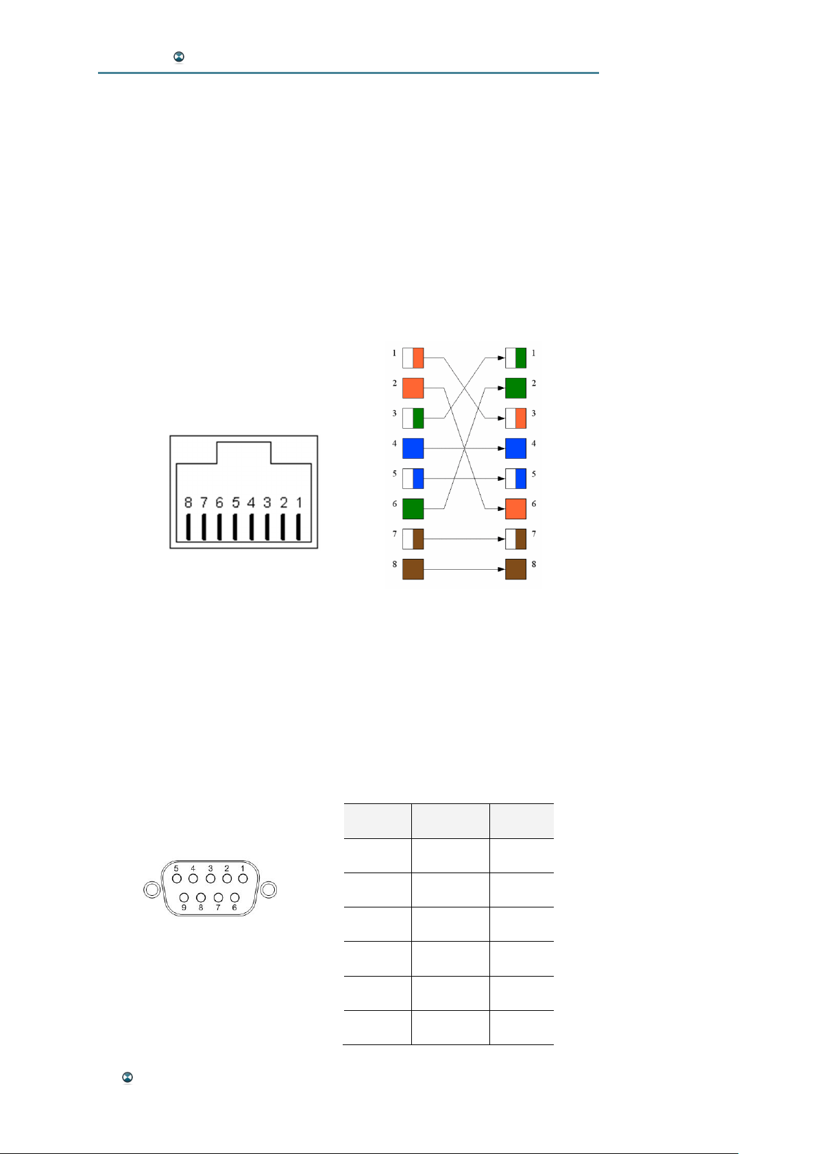
The link port is used to connect two ISOSTEM®Live units in redundant
mode.
In a daisy-chained setup, a standard CAT5 cross-link cable interconnection
is mandatory for automatic processing/bypass-handshake and backupswitchover.
In a redundant parallel setup, a device interconnection is not mandatory.
Future software extensions will enable the link port´s integrated data interface for automatic parameter/preset synchronization.
View of RJ45 link port from
rear side of device
Required CAT5 cross-link pin assignment
Pin assignment of Link Port and specification of cross-link cable
RS232
The RS232 interface enables a PC connection for running the GUI software.
Function Direction Pin#
TXD Out 2
RXD In 3
CTS In 7
View of female SUB-D 9-pol.
RS232 interface on rear side
RTS Out 8
48 Appendix
GND 5
SHIELD CASE
Page 49
ISOSTEM USER MANUAL
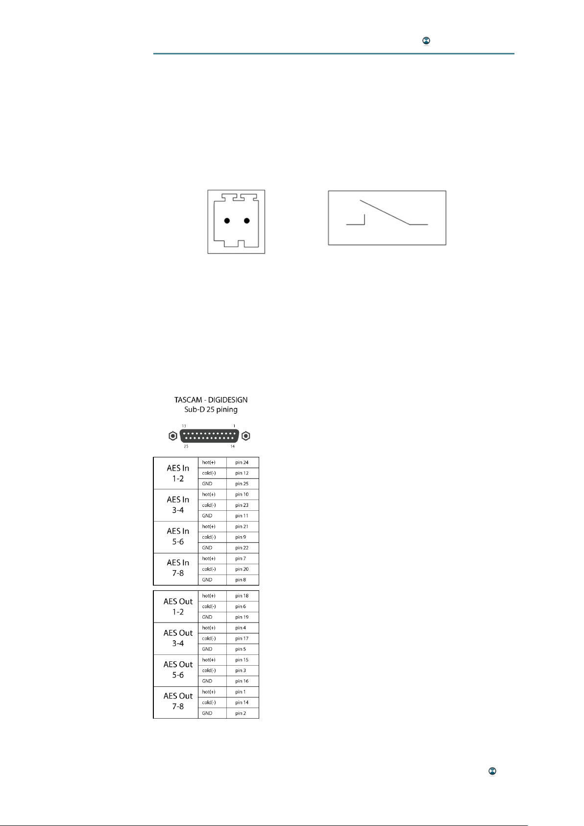
ALARM PORT
The alarm port indicates the device status electrically. It is a 2-pin 2.5 mm
PHOENIX-male connector. Internally, the two pins are connected to relay
contacts – thus it is a fully passive interface with two states:
Contacts closed: No alarm, device fully functional.
Contacts open: Device failure or no power supplied.
Max. load to relay contacts: 2 mA/250 VAC
WORD CLOCK INPUT
1 x BNC max. 2..5Vp-p
AES/EBU INTERFACE
The AES/EBU connector wiring is compatible to the Tascam pinout:
Appendix 49
Page 50
ISOSTEM USER MANUAL
APPENDIX B: SCHEMATIC BLOCK DIAGRAM
50 Appendix
Page 51
ISOSTEM USER MANUAL
Appendix 51
Page 52
ISOSTEM USER MANUAL
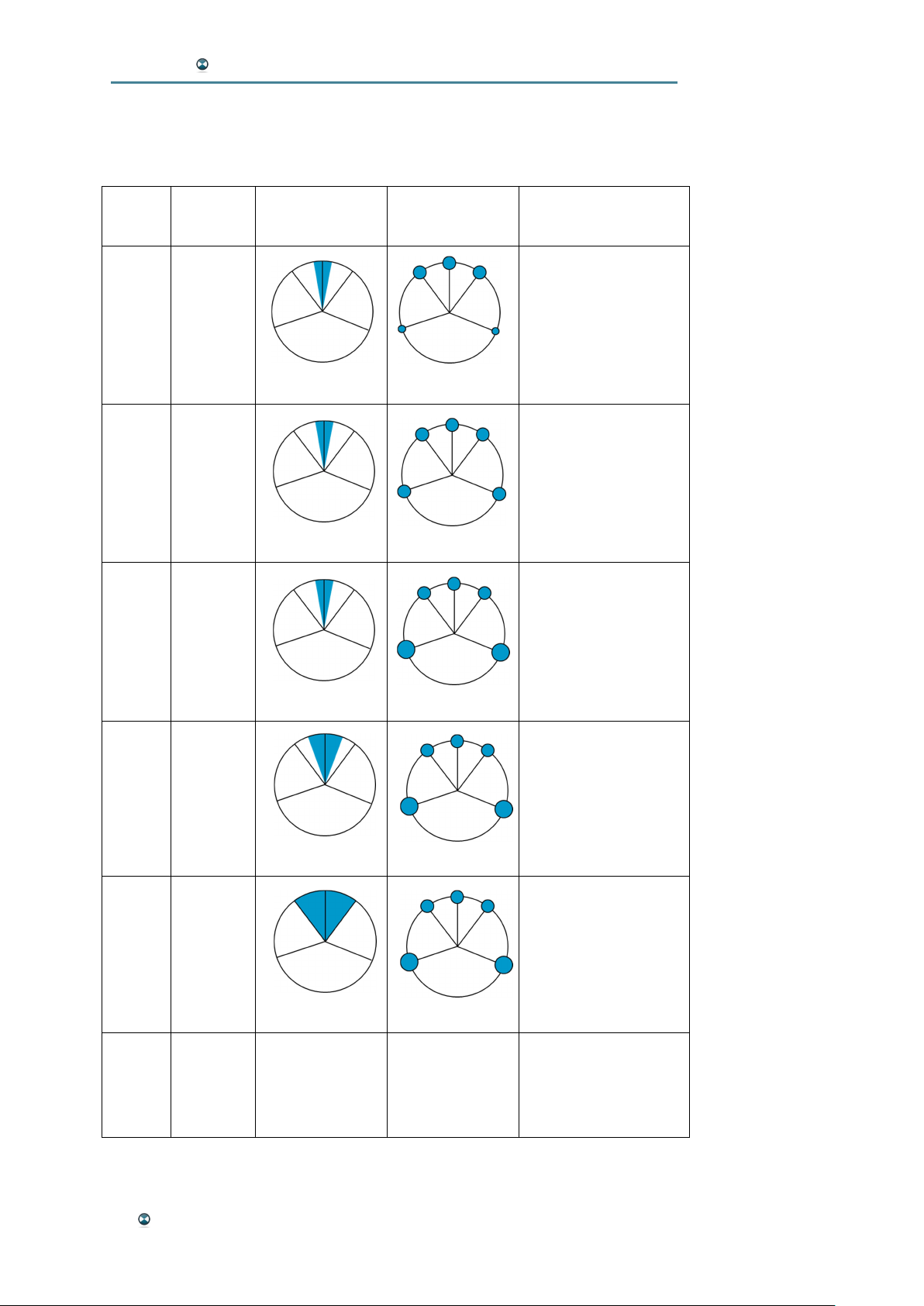
APPENDIX C: FACTORY PRESETS
Preset
1 Upmix
2 Upmix
3 Upmix
Type Diversity Rear Level Input / Ouput
Stereo In: AES 4 In
Upmix L/R: AES 1 Out
Upmix C/LFE: AES 2 Out
Upmix sL/sR: AES 3 Out
narrow
narrow
narrow
discreet
middle
strong
Stereo out: AES 4 Out
Stereo In: AES 4 In
Upmix L/R: AES 1 Out
Upmix C/LFE: AES 2 Out
Upmix sL/sR: AES 3 Out
Stereo out: AES 4 Out
Stereo In: AES 4 In
Upmix L/R: AES 1 Out
Upmix C/LFE: AES 2 Out
Upmix sL/sR: AES 3 Out
Stereo out: AES 4 Out
Stereo In: AES 4 In
4 Upmix
middle
5 Upmix
wide
6 Bypass -/- -/- AES 1..4 In : AES 1..4 Out
strong
strong
Upmix L/R: AES 1 Out
Upmix C/LFE: AES 2 Out
Upmix sL/sR: AES 3 Out
Stereo out: AES 4 Out
Stereo In: AES 4 In
Upmix L/R: AES 1 Out
Upmix C/LFE: AES 2 Out
Upmix sL/sR: AES 3 Out
Stereo out: AES 4 Out
Please note: These presets represent the factory settings of firmware v3.0.
52 Appendix
Page 53
ISOSTEM USER MANUAL
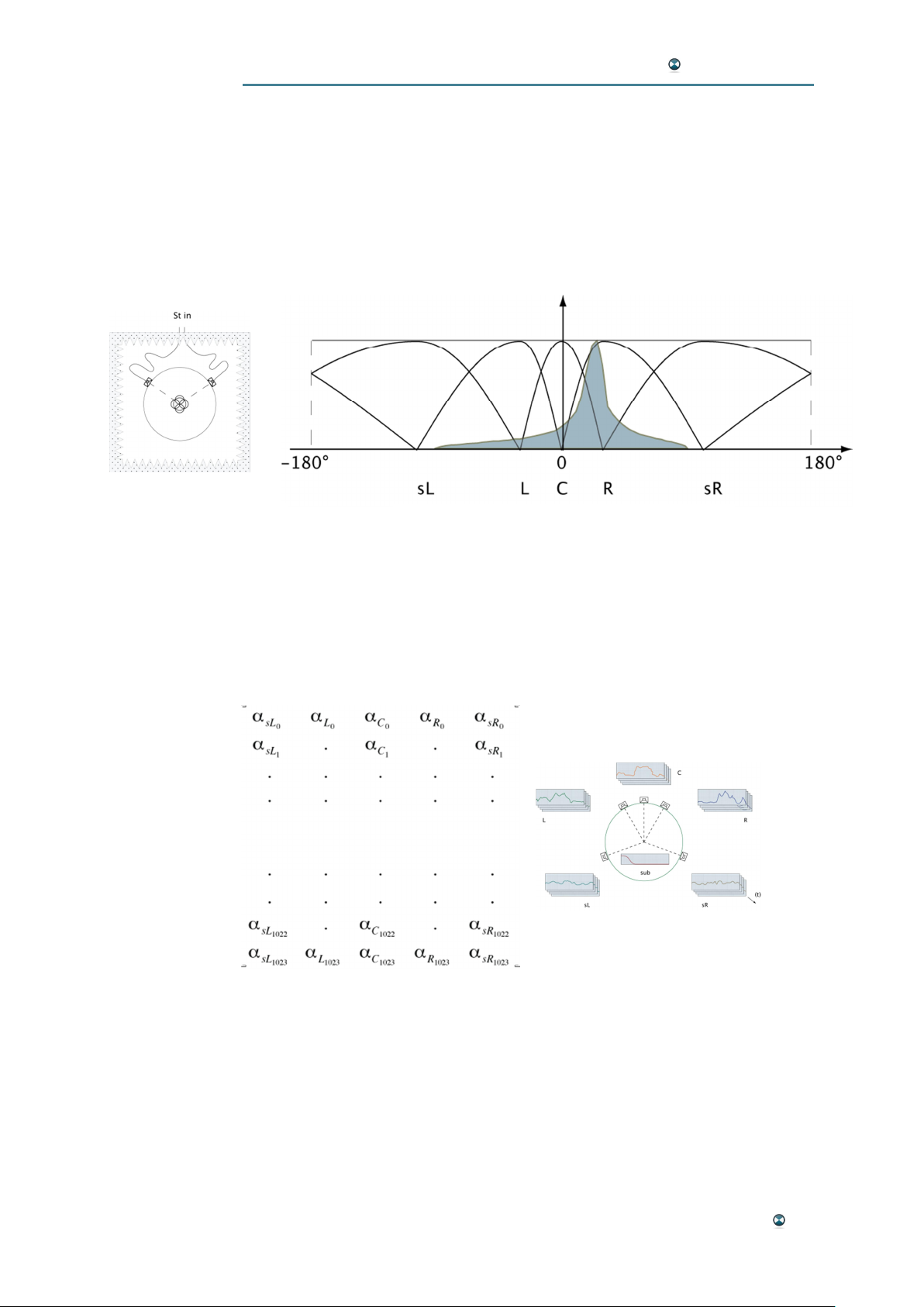
Acoustic
Simulation
APPENDIX D: PANORAMIC ANALYZER PHYSICS
Acoustic modeling has the goal of extracting the ghost sources of the stereo signal by their positioning in the stereo mix. The signal is treated by
acoustic simulation and the pressure and pressure gradient data establish
the distribution of the energy fluxes in the frequency domain at the listening
point.
Energy Distribution and Panoramic Law
This distribution is modeled, then projected on the panoramic law of the
reproduction system (here five channels in the ITU-R BS.1770 standard),
resulting in a matrix of coefficients normalized for each channel and every
frequency.
Matrix of coefficients Frequency Envelopes
A document itemizing the entire calculation is available in the AES (Audio
Engineering Society) papers library:
AES Paper 6548; AES Convention 119; October 2005.
Appendix 53
 Loading...