

Page 1
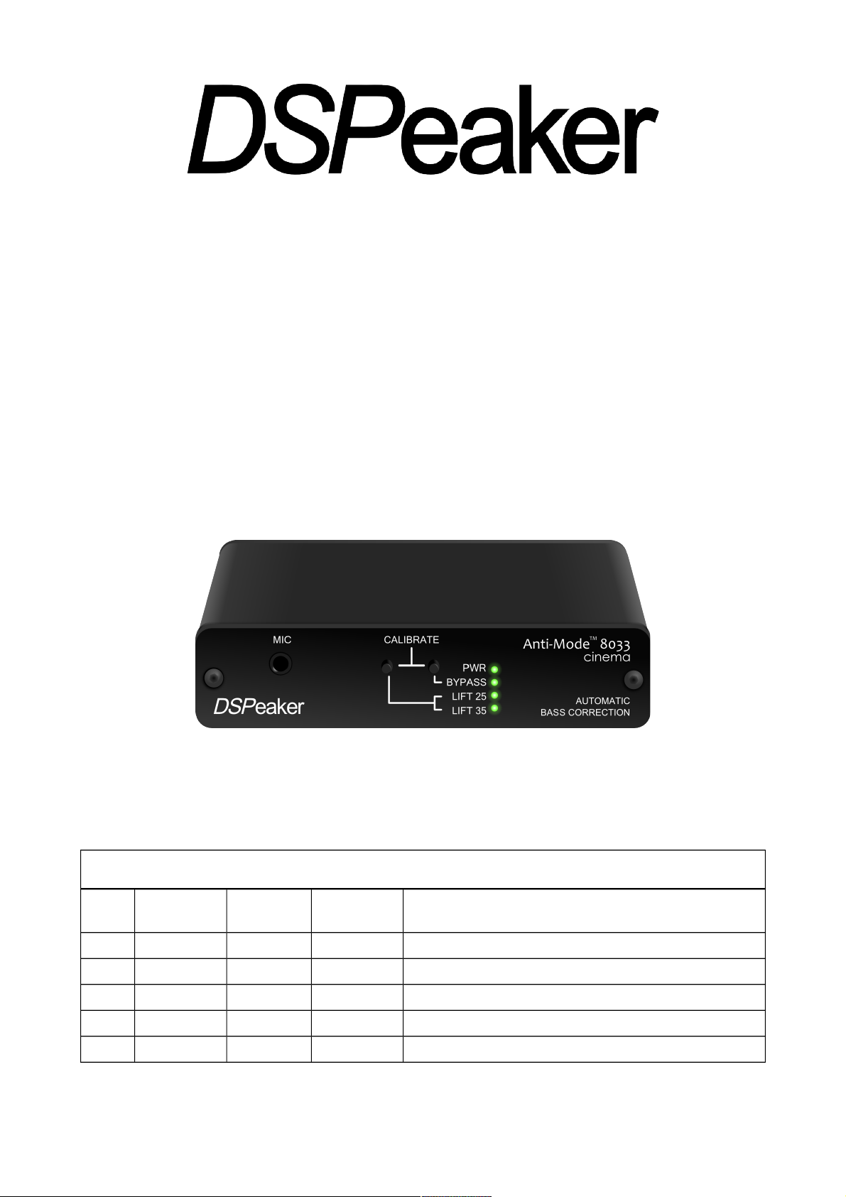
Anti-Mode 8033 cinema
Anti-Mode 8033S-II
User's Manual
Revision History
Rev. Date Author Affected
chapters
Description
1.0 2007-11-30 TK & ToLi All Original version Finnish and English for 8033B
1.8 2012-02-15 POj All Updated for Anti-Mode 8033 cinema and 8033S-II
1.9 2012-03-18 POj All Typo and language corrections
2.0 2012-04-23 LMa All New layout, graphics
2.1 2019-03-21 POj All Updated contact information, phrasing changes.
Page 2

Recycling information
The product you have purchased is marked according to the Waste
Electrical and Electronic Equipment Directive (WEEE Directive). There
are take-back systems in place that help to preserve nature and natural
resources when products are disposed of appropriately. If you need to
dispose of this product, please use the take-back system that has dedicated collection facilities for
electronic equipment. Do not put the product into household waste disposal!
Also, the product has been manufactured using parts and processes that follow the directive of the
Restriction of the use of certain Hazardous Substances in Electrical and Electronic Equipment
(RoHS).
Intended Use
The product has been designed for normal indoor use and be connected to other equipment with
cables not exceeding 3m (10 feet) in length. If you use cables of extended length, check that their
quality is sufficient and observe electrostatic discharge precautions when connecting or
disconnecting them. Use of the product outdoors, in humid or other extreme environments, may
cause reduced performance and/or risks to the user of the equipment.
Page 3

ANTI-MODETM 8033 CINEMA / 8033S-II
Table of contents
1. Connections and Buttons.......................................................................................4
1.1. Front panel.........................................................................................................4
1.2. Back Panel.........................................................................................................5
2. Quick Setup Guide..................................................................................................6
2.1. Before Calibration..............................................................................................7
2.2. Calibration..........................................................................................................7
2.3. After Calibration..................................................................................................8
2.4. Subwoofer Placement........................................................................................9
2.5. Crossover Frequency.........................................................................................9
2.6. Multiple Subwoofers.........................................................................................10
3. Wider Area Correction..........................................................................................10
3.1. Strategy 1, “Compensation of the Worst Response Point”..............................11
3.2. Strategy 2, “Gradient Compensation”..............................................................11
4. Basic operation.....................................................................................................12
4.1. Bypass mode...................................................................................................12
4.2. Lifting EQ.........................................................................................................12
4.2.1. Flat.................................................................................................................. 12
4.2.2. Lifting 15-25Hz................................................................................................ 12
4.2.3. Lifting 25-35Hz................................................................................................ 12
4.2.4. Subsonic Filter Only........................................................................................ 13
4.2.5. Lifting 20-30Hz (Anti-Mode 8033S-II)..............................................................13
4.3. Input Level Warning.........................................................................................13
4.4. Output Level Warning......................................................................................14
4.5. Powering Up and Down...................................................................................14
4.6. Low-pass Filter Selection (Anti-Mode 8033S-II)..............................................14
5. Connection Examples...........................................................................................17
6. Frequency Responses..........................................................................................18
6.1. Lift and Subsonic.............................................................................................18
6.2. Low-pass Filter Responses (Anti-Mode 8033S-II)...........................................19
6.3. Dipole Correction Responses (Anti-Mode 8033S-II).......................................19
7. Technical Specifications.......................................................................................20
8. Manufacturer..........................................................................................................20
9. Contact...................................................................................................................20
Rev. 2.1 29.03.2019 Page 3 (20)
Page 4
ANTI-MODETM 8033 CINEMA / 8033S-II
1. Connections and Buttons
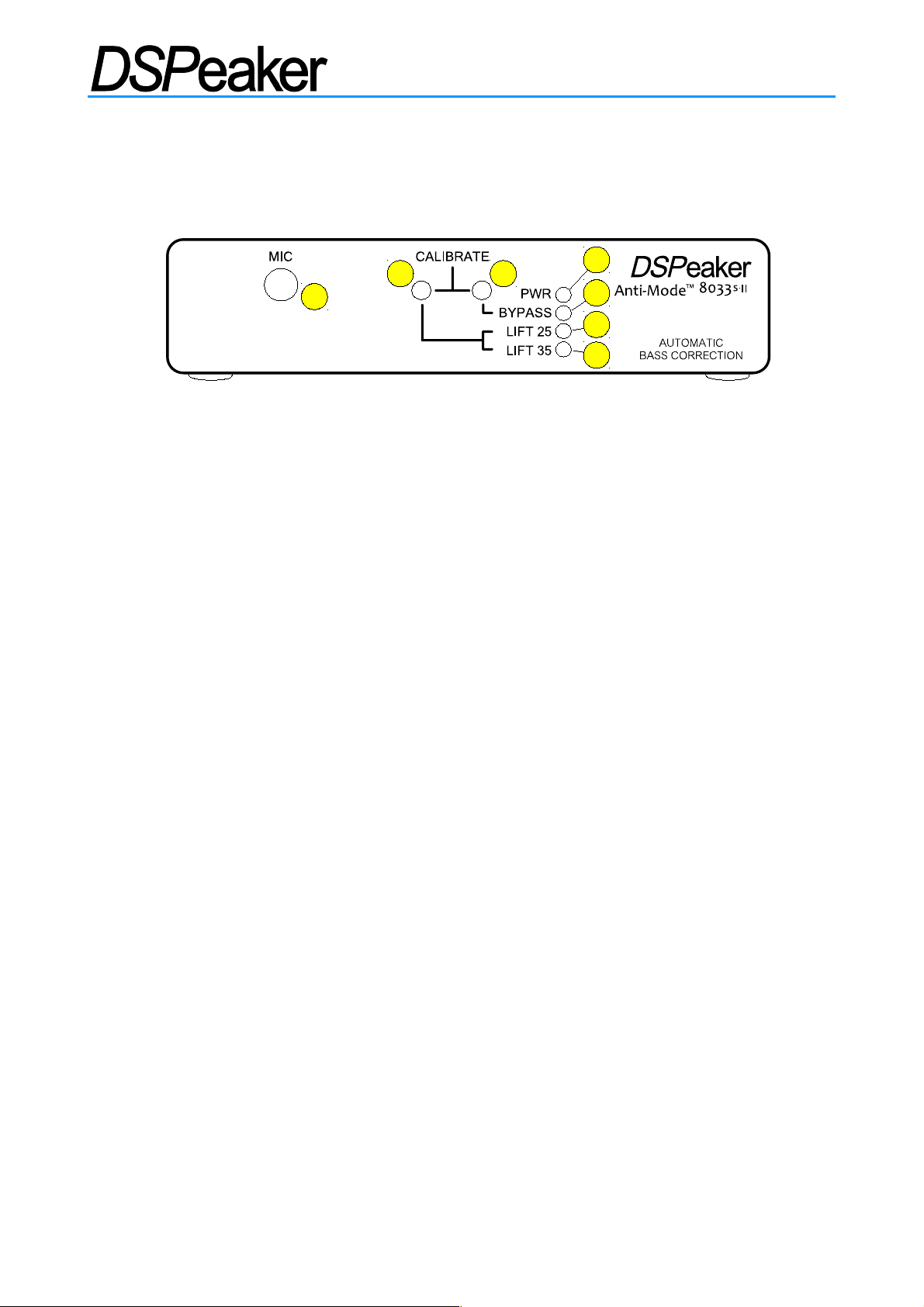
1.1. Front panel
1. Microphone input jack.
2. LIFT Button: LIFT25 / LIFT35 / FLAT selector.
• Short press: Selects low frequency boost mode.
• Long press (with bypass off): Stores current settings.
• Long press (with bypass on): Enter filter selection mode (Anti-Mode 8033S-II).
3. BYPASS Button: BYPASS selector.
• Short press: Toggle Bypass mode (disable / enable processing)
• Long press: Begin secondary calibration for Wide Area Correction.
• Long press of both LIFT and BYPASS buttons: Begin main calibration.
4. PWR LED: Lit when the device is on.
• Flashes in filter edit mode, other LEDs show selected filter (Anti-Mode 8033S-II).
5. BYPASS LED: Lit when the Anti-ModeTM correction and lifts are bypassed.
• Flickers for 3dB input level warning (if flickers constantly, please reduce input level)
6. LIFT25 LED: Lit when the 15-25Hz lifting EQ (equalization) and subsonic filter is on.
• Is dimly lit along with the LIFT35 LED when the subsonic filter is active without lift.
• Flashes during calibration.
• Flickers for output saturation warning (please reduce input level).
7. LIFT35 LED: Lit when the 25-35Hz lifting EQ and subsonic filter is on.
• Is dimly lit along with the LIFT25 LED when the subsonic filter is active without lift.
• Flickers for input overdrive warning (please reduce input level).
Level warnings create an irregular flickering of the respective LEDs. In calibration and low-pass
filter selection mode the LEDs flash on and off in a steady pace.
Anti-Mode 8033 cinema has yellow LEDs by default.
Anti-Mode 8033S-II has blue LEDs by default.
Rev. 2.1 29.03.2019 Page 4 (20)
1
2 3
4
6
5
7
Page 5
ANTI-MODETM 8033 CINEMA / 8033S-II
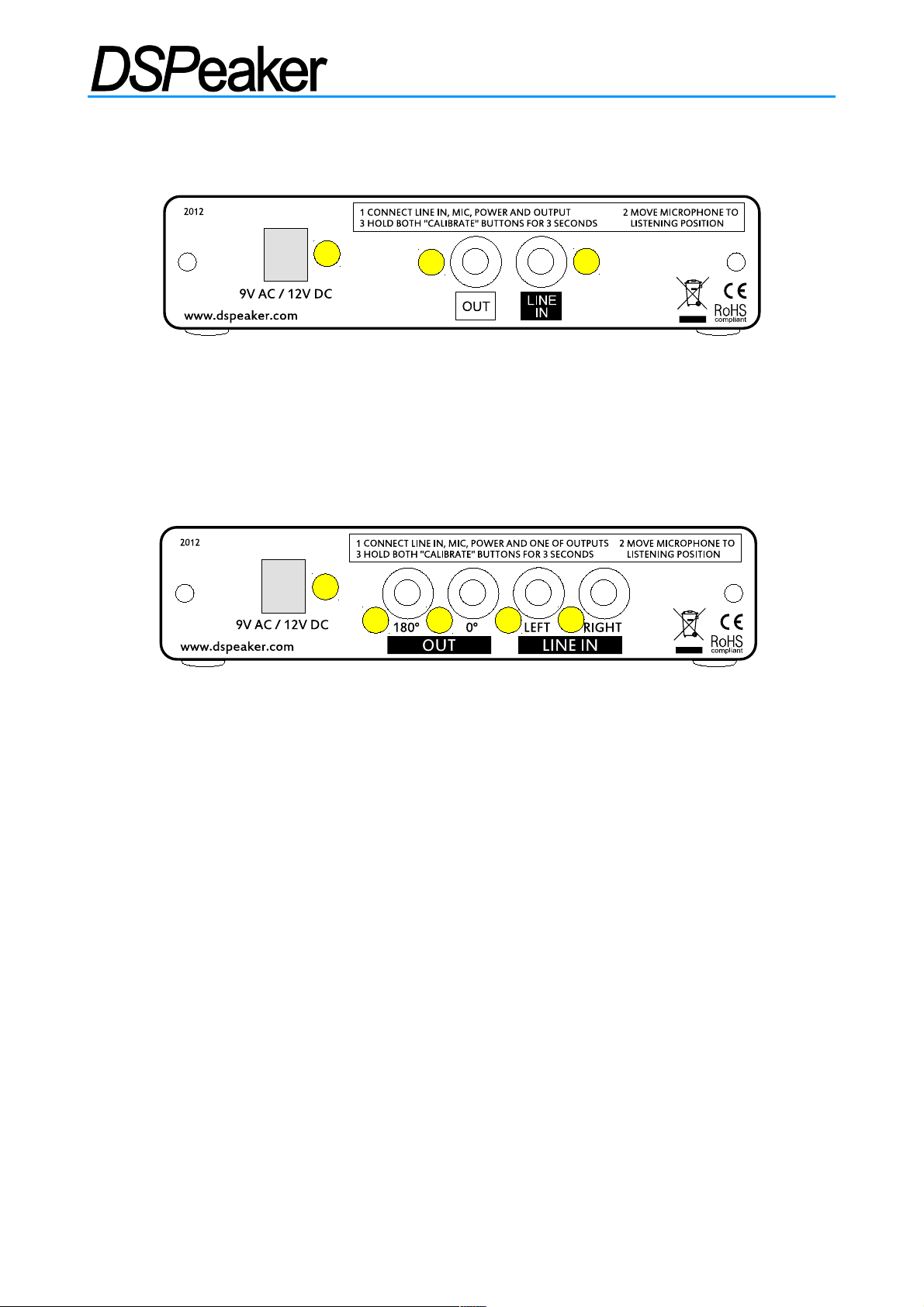
1.2. Back Panel
Anti-Mode 8033 cinema
1. 9 VAC / 12 VDC connector: Input power.
2. LINE OUT / RCA connector: To subwoofer.
3. LINE IN / RCA connector: Low-Frequency-Effects (LFE) or subwoofer (SUB) signal
from the pre-amplifier or Audio/Video Receiver (AVR).
Anti-Mode 8033S-II
1. 9 VAC / 12 VDC connector: Input power.
2. OUT 180° connector: Inverted-phase RCA out.
3. OUT 0° connector: In-phase RCA out (to subwoofer, default)
• A balanced XLR output can be created by combining the signals from the OUT 0 °
and OUT 180° connectors.
4. LEFT LINE IN / RCA connector: LFE or SUB signal from the pre-amplifier or AVR.
5. RIGHT LINE IN / RCA connector: LFE or SUB signal from the pre-amplifier or AVR.
If your subwoofer has two inputs, do not connect both 0° and 180° outputs to it, because their
sum is zero.
If your AVR has two dedicated LFE outputs, only connect one of them.
The dual LEFT / RIGHT inputs can be used to connect stereo systems that have only stereo preamplifier outputs instead of a dedicated LFE output. You can also connect your home theater LFE
output to the LEFT input and a stereo system to the RIGHT input using an optional stereo to mono
summing cable.
Both Anti-Mode 8033 models can also be connected to speaker-level outputs using a power
reduction device or a suitable resistor divider cable.
Rev. 2.1 29.03.2019 Page 5 (20)
1
2
3
1
3
5
2 4
Anti-Mode 8033 cinema Back Panel
Anti-Mode 8033S-II Back Panel
Page 6
ANTI-MODETM 8033 CINEMA / 8033S-II
2. Quick Setup Guide
1. Please read the rest of the manual to get the most out of your system and the Anti-
Mode 8033.
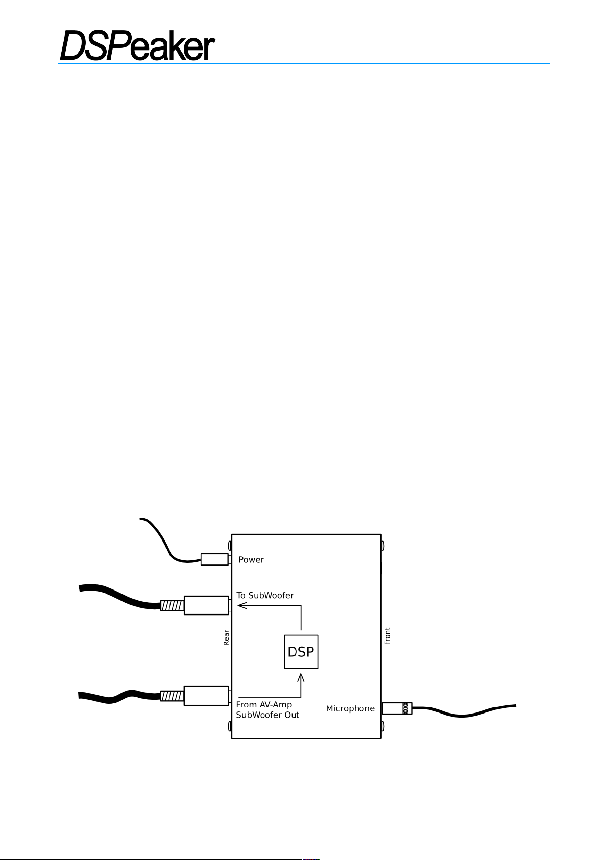
2. Connect the subwoofer signal to "LINE IN" (LEFT input on the 8033S-II).
3. Connect the active subwoofer or subwoofer amp to “LINE OUT” (or OUT 0°) output.
4. Connect the microphone plug to the "MIC" jack and place and fix the microphone as
close to the listening position (head of the listener) as possible. Use of a microphone
stand helps with correct microphone placement.
5. Connect the power supply to the "9 VAC / 12 VDC" connector and wall socket.
6. Anti-Mode 8033 will turn on automatically when you plug it in.
7. Note: All LEDs on the front panel are lit if the device has never been calibrated.
8. Switch on the subwoofer and reduce its volume setting moderately.
9. Press and hold both LIFT and BYPASS buttons for three seconds to start the first
(main) calibration process. Release the buttons when the LIFT25 LED starts flashing.
10. If you keep holding the calibrate buttons down the calibration process will be aborted.
Anti-ModeTM calibration will generate up to 7 frequency sweeps (depending on the complexity of
the correction required). The calibration process usually lasts 15-30 minutes. When the LIFT25
LED stops flashing the calibration process is completed.
For best results, run your AVR's speaker setup to set speaker levels and distances after the Anti-
ModeTM calibration has finished.
Rev. 2.1 29.03.2019 Page 6 (20)
Setting up Anti-Mode 8033
Page 7

ANTI-MODETM 8033 CINEMA / 8033S-II
2.1. Before Calibration
If you have a small reflex subwoofer, decrease its volume before calibration. If the subwoofer has
a built-in low-pass or other type of filter, it should be deactivated before the calibration process and
can be re-activated after calibration. Crossover and low-pass filters in the AVR do not affect
calibration since they take place before the Anti-Mode 8033 in the signal chain. Also, any other
audio equipment connected before the Anti-Mode 8033 will not take part in the calibration process.
Pay close attention to the vertical positioning (height) of the calibration microphone since it affects
proper room mode detection. The microphone is omnidirectional, so its precise orientation doesn't
matter. If you use your subwoofer with doors and windows closed, keep them closed during the
calibration. If you want the room correction to affect a wider area, the first calibration point should
be selected near the center of the listening area (or the primary listening position). More about
Wider Area Correction in section 3.
2.2. Calibration
If you have the Anti-Mode 8033S-II model and a dipole (open-baffle) subwoofer, select the
preferred dipole correction mode before starting the calibration. (See the section 4.6 on "Low-pass
Filter Selection".)
Press both the LIFT and BYPASS buttons on the front panel and hold them down to start the
calibration process. Make sure that both of the buttons are pressed down at the same time. After a
couple of seconds the LIFT25 LED starts flashing and the calibration begins. Now release the
buttons and wait for the automatic calibration to finish. The measurement program analyzes the
room utilizing four to seven frequency sweeps.
The calibration starts with a moderate output volume. The measurement routine allows wide range
of input levels. The input level warning LED (BYPASS LED) starts to flicker if less than 3.0 dB of
headroom is left during measurement. If this persists the generated output level is automatically
adjusted down. If the microphone is near overflow, the sweep is restarted.
The calibration process is very robust and it tolerates background noise very well, therefore
speech and small noises do not affect the process. However, one should avoid making loud
noises, especially near the microphone. For example, tapping the microphone or its cable can
cause distortion or overflow the microphone input, causing the calibration process to restart.
Tip: Tapping the microphone with a finger is an easy way to test the microphone, you will see the
BYPASS LED flicker. A harder tap will restart the calibration process.
Rev. 2.1 29.03.2019 Page 7 (20)
Page 8

ANTI-MODETM 8033 CINEMA / 8033S-II
If you initiate the calibration process by mistake, you can abort it by pressing either the LIFT or
BYPASS buttons. This will restore your saved settings, including the lift settings (and other filter
settings for the Anti-Mode 8033S-II).
The calibration is automatically aborted after one sweep if the microphone is not connected
properly, is faulty, or the calibration signal is not detected (for example, the subwoofer is not turned
on). The previously saved settings are restored also in this case.
2.3. After Calibration
Once the last sweep is over, the calibration process is finished. The subsonic filter is automatically
activated. The results are stored in a non-volatile memory inside the unit so they are not lost if the
Anti-Mode unit loses power. Anti-Mode 8033 is now fully functional and the microphone can be
removed, unless the user wishes to perform Wider Area Calibration.
After calibration the subwoofer may sound more quiet. This is partly because the overall sound
level decreases when the room resonances are suppressed, and also it just sounds more quiet
because you have been used to peaks in the audio output. It may take a while to get accustomed
to the new sound, but you quickly start to notice sounds on frequencies that were drowned out by
the untreated peaks. The calibration process raises the overall level, so the subwoofer volume
needs to be increased only slightly (1-6 dB). For best results perform this adjustment using the
AVR's subwoofer volume control.
If the AVR supports speaker distances, you can add 90 cm (~36 inches) to the subwoofer distance
relative to other speakers to compensate for the internal processing delay. This is not absolutely
necessary since the delay is small enough that the human auditory system generally cannot detect
it.
You can also use your AVR's setup functions to determine the correct distance and level settings.
In this case, the processing latency of the Anti-Mode and the new subwoofer level are
automatically taken into account by the AVR and you do not need to adjust them yourself. Use the
AVR's “small” speaker setting for best results. First calibrate the Anti-Mode, then perform the AVR
calibration so it sees the corrected response.
Important! If only one sweep signal was generated during the calibration, one of the following
situations occurred: the microphone was not properly connected, the calibration signal was not
detected, or the calibration was aborted. If only two sweeps were generated, perhaps both buttons
Rev. 2.1 29.03.2019 Page 8 (20)
Page 9

ANTI-MODETM 8033 CINEMA / 8033S-II
on the front panel were not pressed and you performed a secondary calibration. In any case, the
calibration process must be restarted.
Whenever the placement of the subwoofer or listening position changes (or you change the dipole
correction in Anti-Mode 8033S-II), the initial calibration should be performed again to ensure an
optimal result.
2.4. Subwoofer Placement
There are several methods available on how to determine the best place for your subwoofer. Due
to room reflections creating resonances, some frequencies are amplified (room modes / peaks)
and some are attenuated (nulls / dips). Without a sub EQ device, you need to locate the
subwoofer in a place that creates the flattest possible response in your room.
However, with Anti-ModeTM you do not need to be concerned about room modes because they are
effectively corrected. Instead, you should concentrate on minimizing the number of cancellation
nulls, because these cannot be corrected by a sub EQ device.
With Anti-ModeTM the best place for subwoofer(s) is near the corners of the room. This causes the
room modes to be excited maximally, but reduces the occurrence of nulls. The reflections from the
floor and the walls are in the same phase as the direct sound, and this boundary reinforcement
allows the subwoofer(s) to reproduce lower frequencies without using extra power. Remember to
the Anti-ModeTM calibration after relocating the subwoofer(s).
What was once considered the worst place to locate a sub is now the best place when using Anti-
Mode!
2.5. Crossover Frequency
The appropriate crossover frequency depends on the capabilities of the subwoofer and the main
speakers. The main speakers should be set to “small” in the AVR so that only the subwoofer
(whose response is corrected) is responsible for reproducing the low frequencies.
With Anti-ModeTM correction the subwoofer integration with the speakers should be more effortless.
You are now able to use a higher crossover frequency than the standard 80Hz setting without the
subwoofer becoming localizable. We recommend trying 100Hz or 120Hz crossover setting.
Because there are differences between individuals, let your ears decide which setting is best for
you. You can change the crossover setting from the AVR without recalibrating.
Rev. 2.1 29.03.2019 Page 9 (20)
Page 10

ANTI-MODETM 8033 CINEMA / 8033S-II
2.6. Multiple Subwoofers
Having multiple subwoofers reproducing the same signal (dual mono) will result in a smoother
response in general. Anti-Mode 8033 can be used with any number of subs and allows you to use
corner placement for the subs. Connect the Anti-Mode unit to the signal going into each sub, and
calibrate them together. When calibrated together, the nulls created by one sub are filled in by the
other sub. Anti-ModeTM calibration takes this into account, creating a smoother overall response
than if the subs were calibrated separately using multiple Anti-Mode units.
If you want to reproduce low frequencies in stereo, you need either two Anti-Mode 8033's or one
Anti-Mode 2.0 Dual Core. Stereo at low frequencies is generally not needed, because low
frequencies are omnidirectional and predominantly mixed in mono. Any directional cues are
determined from harmonics and other aural information. It is usually better to use the dual mono
arrangement instead of stereo to get a more even response.
3. Wider Area Correction
In some situations it is more favorable to compensate for room acoustics in a wider listening area.
When this is done, the result is no longer optimal in any single listening position, but is improved
for a wider listening area. Before performing wider area correction, the first (main) calibration
procedure described in the earlier section must be performed. As previously discussed, the first
calibration is done with the microphone at the center of the listening area or primary listening
position within the area.
The Anti-Mode 8033 can be calibrated for wider areas by moving the microphone to another point
within the listening area. Pressing and holding the BYPASS button will initiate a secondary
calibration utilizing two to three additional frequency sweeps. Anti-Mode 8033 will use the results
from these sweeps in conjunction with data gathered from the first calibration to create a
compensation model for a wider listening area.
Do not accidentally keep both the LIFT and BYPASS buttons pressed on the front panel as this will
start the first (main) calibration all over again overriding the current calibration.
Secondary calibrations can be done multiple times and will not result is the loss of data from the
first (main) calibration. The previous secondary calibrations will not be retained. It is easy to try
different secondary calibration points for the best audible result. The following lists two main
strategies for choosing the microphone position for the secondary calibration.
Rev. 2.1 29.03.2019 Page 10 (20)
Page 11

ANTI-MODETM 8033 CINEMA / 8033S-II
3.1. Strategy 1, “Compensation of the Worst Response Point”
When the first (main) calibration is performed at the primary listening position or at the center of
the listening area, you can then evaluate the result by listening at different positions around the
room.
If the result is not adequate at some location, that location can be used as a secondary calibration
point. Also any location between the secondary point and the first point can lead to good results.
Inevitably, the result will get less optimal at the first point, but is usually improved everywhere else,
including the worst response point.
3.2. Strategy 2, “Gradient Compensation”
If it is difficult to find the worst response point in the listening area, gradient compensation is a
good approach. Decide the secondary calibration point by moving the microphone from the first
calibration point toward the closest corner of the listening room by 40-90 cm (16 to 36 inches) and
downward (toward the floor) approximately 10-20 cm (4 to 8 inches).
Perform the secondary calibration with the microphone in this position. If the first calibration point
was closer than a meter (39 inches) from the wall, the microphone should be moved only about
20-40 cm (8 to 16 inches) toward that wall for the secondary calibration.
The gradient compensation method works well in removing the resonances arising from reflections
between opposing walls or floor/ceiling (axial modes) for larger areas in a rectangular room.
Rev. 2.1 29.03.2019 Page 11 (20)
Page 12
ANTI-MODETM 8033 CINEMA / 8033S-II
4. Basic operation
4.1. Bypass mode
If you want to compare the corrected and uncorrected operation, press the
BYPASS button quickly. This will switch between bypass and normal mode. The
first press will set bypass mode, which is also indicated by the BYPASS LED being
lit. If the Bypass mode is already active, the unit switches back to normal mode. In bypass mode
no room corrections are active and user selected lifting EQ is turned off. Low-pass or dipole
corrections remain active in bypass mode (Anti-Mode 8033S-II only).
4.2. Lifting EQ
The LIFT button switches between the EQ settings of Anti-Mode 8033. The chosen setting is
stored with a longer press of the LIFT button. A brief sound is heard from the subwoofer after
settings have been stored, indicating that you should release the LIFT button. (Keep the LIFT
button pressed for additional 10 seconds for factory reset.)
4.2.1. Flat
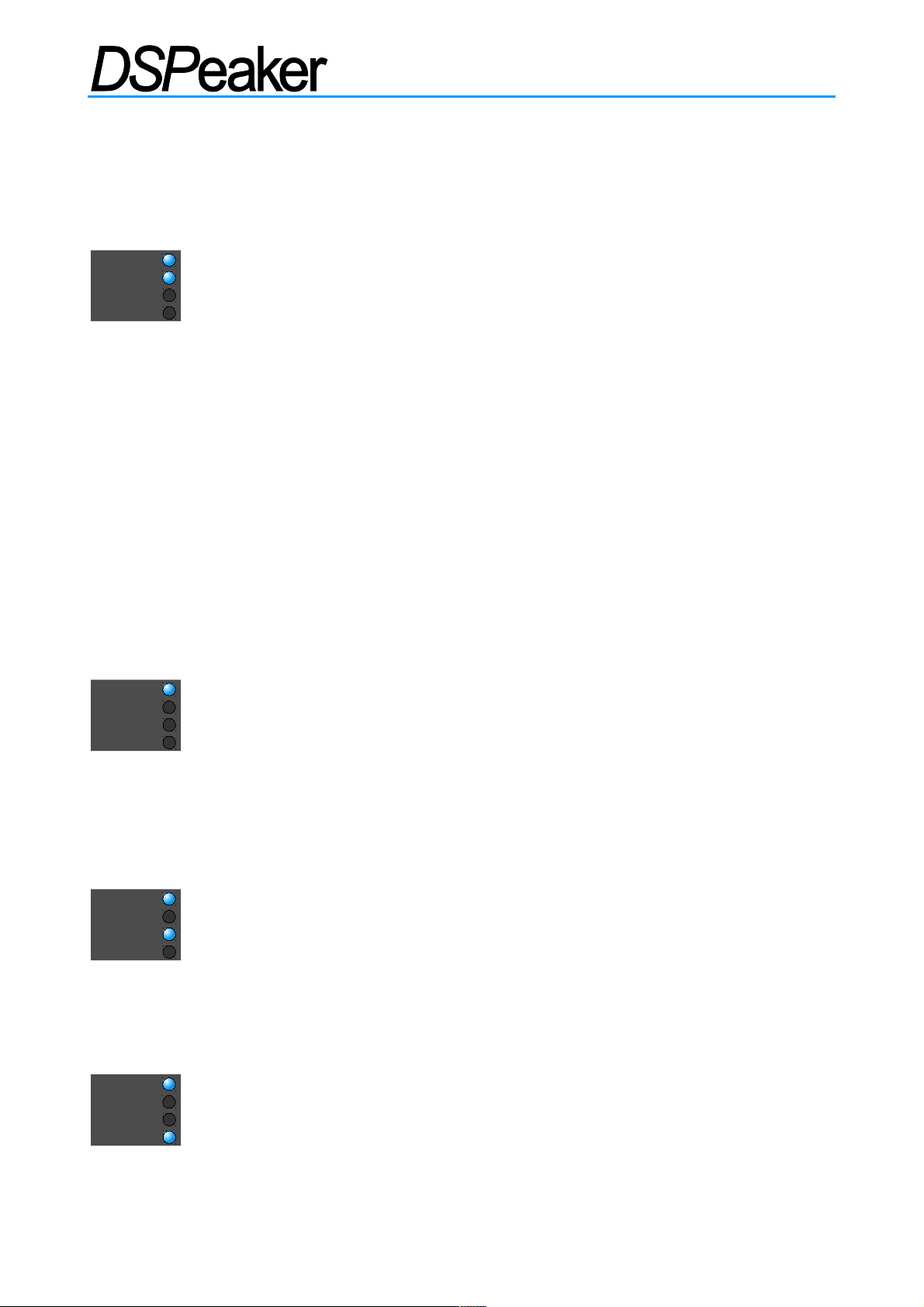
The first EQ setting is “flat” or no lifting. Neither the LIFT25 nor LIFT35 LED are lit.
In this setting, the target response is flat from 5Hz to 160Hz (Anti-Mode 8033
cinema) or to 250Hz (Anti-Mode 8033S-II). This setting is automatically changed to
Subsonic-Filter-Only after the first (main) calibration. You can override this and save the new
setting.
4.2.2. Lifting 15-25Hz
The second EQ setting is LIFT25. When the LIFT25 LED is lit, Anti-Mode boosts
frequencies between 15 and 25Hz (max. 8dB at 20Hz). This will also activate a
digital infrasonic filter, which will filter out frequencies below 10Hz, which can be
dangerous to ported subs that do not have a proper high-pass filter.
4.2.3. Lifting 25-35Hz
The third EQ setting is LIFT35. When LIFT35 LED is lit, Anti-Mode boosts
frequencies between 25-35Hz (max. 8dB at 30Hz). As with LIFT25, the digital
infrasonic filter is also activated.
Rev. 2.1 29.03.2019 Page 12 (20)
PWR
BYPASS
LIFT 25
LIFT 35
PWR
BYPASS
LIFT 25
LIFT 35
PWR
BYPASS
LIFT 25
LIFT 35
PWR
BYPASS
LIFT 25
LIFT 35
Page 13
ANTI-MODETM 8033 CINEMA / 8033S-II
4.2.4. Subsonic Filter Only
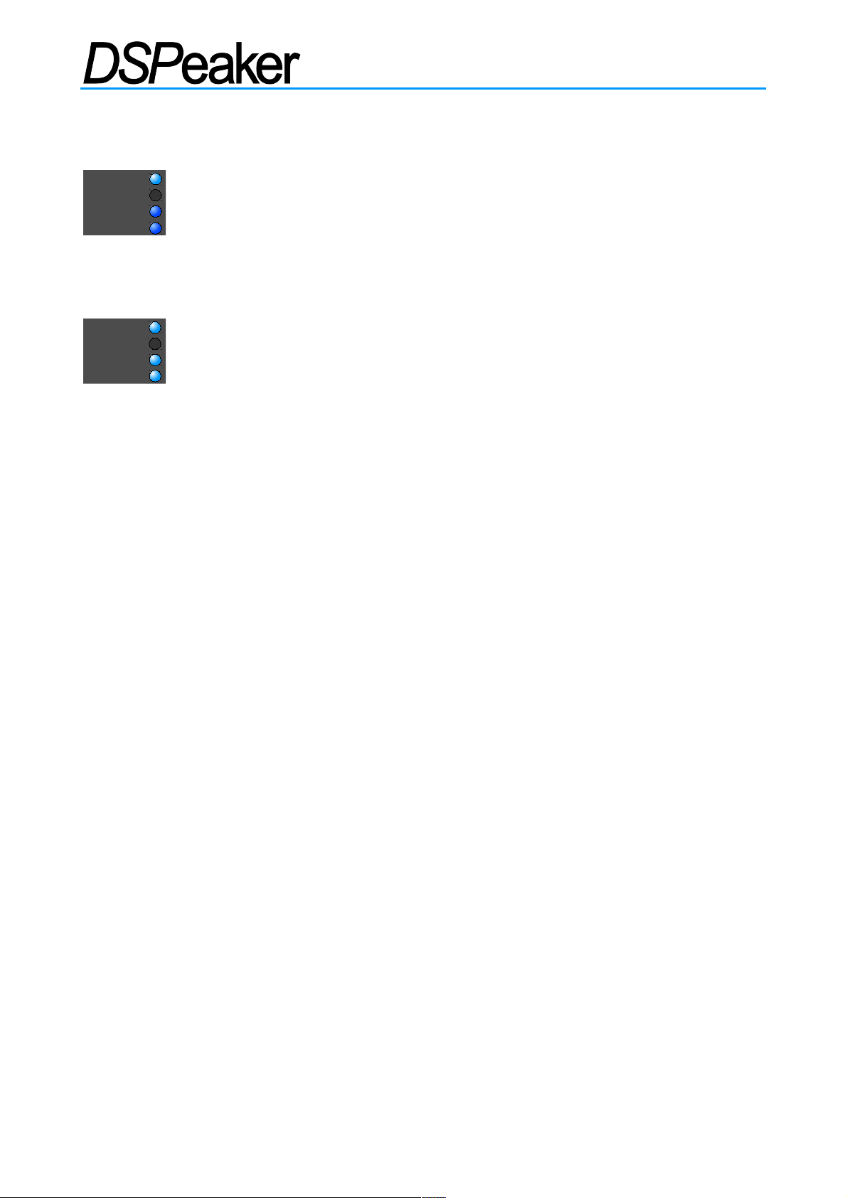
A fourth EQ setting activates the digital subsonic filter without any lift. The Subsonic-
Filter-Only mode is active when the LIFT25 and LIFT35 LEDs are dimly lit. The “flat”
setting is automatically changed to this setting after the first (main) calibration.
4.2.5. Lifting 20-30Hz (Anti-Mode 8033S-II)
The Anti-Mode 8033S-II has an additional EQ setting. Quickly press the LIFT button
until both LIFT25 and LIFT35 LEDs are fully lit. This mode gives about 8dB of lift at
25Hz. The digital infrasonic filter is also activated.
All lifting modes decrease the overall level of the signal by 3 dB to reduce the risk of
clipping / saturating the output signal. Listening tells you which one of the lifting settings
gives best results. The 'flat' and 'subsonic-filter-only' settings are probably the best options
for music, because they give the most accurate transient response.
Lift modes are not recommended when the dipole correction is active.
4.3. Input Level Warning
If the input signal level in the Anti-Mode 8033's Analog to Digital Converter (ADC) is near the
maximum input range, the user is warned in two stages. If the input signal level has only 3 dB of
headroom remaining, the BYPASS LED will start flickering. If the level increases from this, the
signal starts to saturate at the ADC input and harmonic distortion increases. If the input level
reaches maximum, the LIFT35 LED starts flashing. When the input level is reduced the LEDs
resume normal operation.
The input level warning is useful in optimizing the signal level that goes into the Anti-Mode. If the
volume of your subwoofer is too high, the AVR's calibration may set unnecessarily low levels for
the subwoofer output. This leaves much of the Anti-Mode's available input range unused and can
cause an audible low level hum or noise from the subwoofer. This may be the case if your AVR
indicates its subwoofer output level is below -3dB.
To take advantage of the full input range of the Anti-Mode, decrease the subwoofer volume and
increase the output level from the pre-amplifier or AVR until you see only occasional 3dB warnings,
then lower the volume a few dB.
Rev. 2.1 29.03.2019 Page 13 (20)
PWR
BYPASS
LIFT 25
LIFT 35
PWR
BYPASS
LIFT 25
LIFT 35
Page 14

ANTI-MODETM 8033 CINEMA / 8033S-II
The level warning is also active during calibration. During calibration the output level is decreased
automatically if needed (microphone is saturated). The LIFT25 LED flashes to indicate the
progress of calibration.
4.4. Output Level Warning
The Anti-ModeTM correction will raise the overall level of the output depending on how drastic
corrections were applied. This increase and an active lift mode can increase the output level in
some frequencies so much that the signal gets saturated in the output. In this case the LIFT25
LED starts to flicker, and you should decrease the Anti-Mode 8033 input level or turn off lift mode.
4.5. Powering Up and Down
Anti-Mode 8033 cinema and Anti-Mode 8033S-II have almost no power-on and power-off
transients, so you can easily power them on and off using a switchable power cord or the
switchable power output from your AVR.
Anti-Mode 8033 also starts with zero volume and fades in the signal, so it can be powered on
without transients even when an audio signal is already applied to the input connector(s).
Because Anti-Mode 8033 consumes very little power, you may choose to leave it powered on.
4.6. Low-pass Filter Selection (Anti-Mode 8033S-II)
Anti-Mode 8033S-II allows you to select additional filters that remain active while in bypass mode.
Activate Neutral mode if you want to disable low-pass or dipole correction modes.
The low-pass filters are useful when the main speakers cannot reproduce very low frequencies
and the system does not have an adjustable crossover. You can then select the suitable low-pass
frequency to match the natural roll-off point of the main speakers.
Dipole (open-baffle) subwoofers have a natural roll-off of 6dB per octave. If the subwoofer does
not already have a correction circuit to counteract this, the bass will be lacking when the lower
frequencies are reproduced. The dipole correction modes are designed to provide the necessary
6dB/octave boost to the lower frequencies. Because the dipole correction boost is also active
during calibration (the lift modes are not), the Anti-ModeTM correction will work as it was intended
and does not unnecessarily attenuate the higher bass frequencies when it tries to even out the
response.
Rev. 2.1 29.03.2019 Page 14 (20)
Page 15

ANTI-MODETM 8033 CINEMA / 8033S-II
The filter selection mode is activated as follows.
Activate bypass mode by pressing the BYPASS button.
1. Keep the LIFT button pressed until the power LED starts to flash, indicating filter selection
mode.
2. A quick press of the LIFT button selects between the neutral mode and one of the 7 filter
modes. The selected filter is immediately activated.
3. Keep the LIFT button pressed to save the filter selection. A short beep is heard after
settings are saved and the filter selection mode has ended. Release the LIFT button.
4. Quickly pressing the BYPASS button in filter select mode returns the unit to normal mode,
with the selected filter and bypass mode activated. If you now press and hold the LIFT
button, the lift and filter setting will be saved.
Rev. 2.1 29.03.2019 Page 15 (20)
Page 16
ANTI-MODETM 8033 CINEMA / 8033S-II
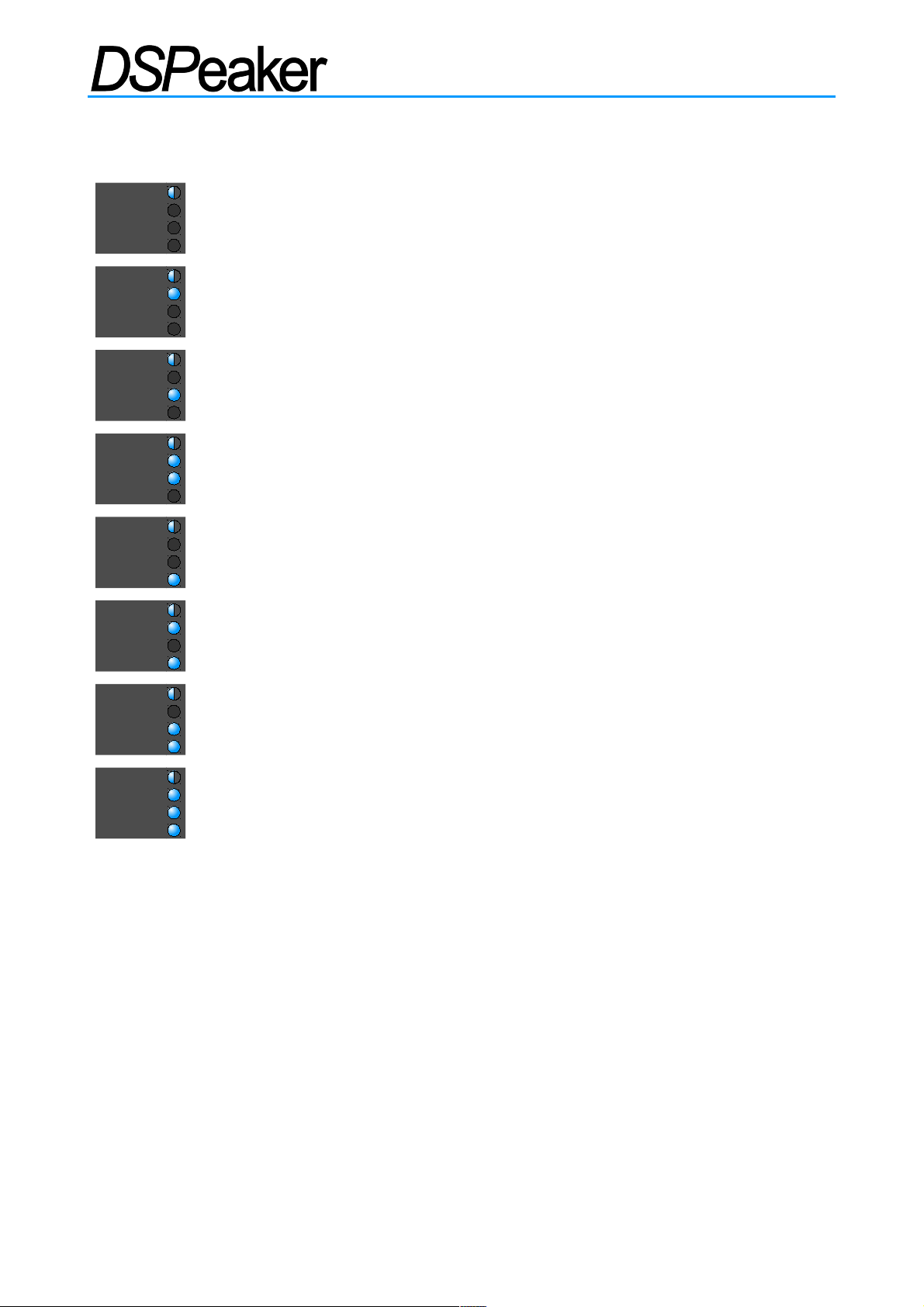
LED indicators for filter modes (PWR LED flashes)
(OFF)
Neutral mode
BYPASS
Low-pass 60 Hz (-3 dB), 3rd order, 18 dB / octave
LIFT25
Low-pass 80 Hz (-3 dB), 3rd order, 18 dB / octave
BYPASS
LIFT25
Low-pass 100 Hz (-3 dB), 3rd order, 18 dB / octave
LIFT35
Low-pass 120 Hz (-3 dB), 3rd order, 18 dB / octave
BYPASS
LIFT35
Low-pass 140 Hz (-3 dB), 3rd order, 18 dB / octave
LIFT25
LIFT35
Dipole correction 20–140 Hz, 6 dB slope, with infrasonic
BYPASS
LIFT25
LIFT35
Dipole correction 20–200 Hz, 6 dB slope, with infrasonic
If you are going to use the dipole modes with your subwoofer, activate and save the filter setting
before performing the Anti-ModeTM calibration. The dipole correction filters are active during
calibration to correct the open-baffle subwoofer's natural attenuation of bass in the lower
frequencies. Other filter modes do not affect calibration and can be activated and deactivated at
any time.
Note: The calibration process always sweeps the entire 16-250Hz (Anti-Mode 8033S-II) range
regardless of the filter selection.
Rev. 2.1 29.03.2019 Page 16 (20)
PWR
BYPASS
LIFT 25
LIFT 35
PWR
BYPASS
LIFT 25
LIFT 35
PWR
BYPASS
LIFT 25
LIFT 35
PWR
BYPASS
LIFT 25
LIFT 35
PWR
BYPASS
LIFT 25
LIFT 35
PWR
BYPASS
LIFT 25
LIFT 35
PWR
BYPASS
LIFT 25
LIFT 35
PWR
BYPASS
LIFT 25
LIFT 35
Page 17
ANTI-MODETM 8033 CINEMA / 8033S-II
5. Connection Examples
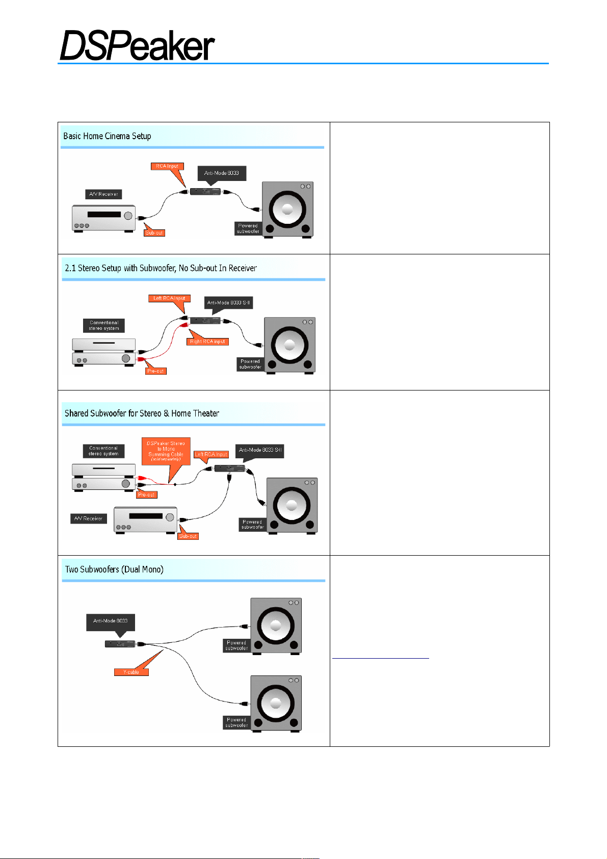
In a basic home cinema configuration, the
Anti-Mode 8033 cinema or the 8033S-II is
connected between the AVR / pre-amplifier
and the subwoofer using line-level
connections.
The dual line inputs of Anti-Mode 8033S-II
are used when connecting into a 2.1
stereo system which has only stereo preouts available (no dedicated LFE or sub
output).
Anti-Mode 8033 cinema can be used, but
it requires an additional stereo to mono
converter cable.
The dual line inputs of the Anti-Mode
8033S-II also allows you to connect both a
home theater and stereo system at the
same time. An additional stereo-to-mono
converter cable is required.
Two or more subwoofers can be
connected using a splitter Y-cable, or by
using the inverted-phase output of the
8033S-II and inverting phase on the subs
connected to it.
See more connection examples at
www.dspeaker.com .
Rev. 2.1 29.03.2019 Page 17 (20)
Page 18
ANTI-MODETM 8033 CINEMA / 8033S-II
6. Frequency Responses
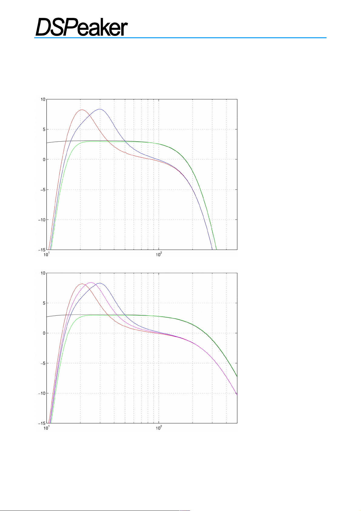
6.1. Lift and Subsonic
Anti-Mode 8033 cinema
(from left to right)
Black: Bypass
Red: Lift 15-25
Blue: Lift 25-35
Green: Subsonic
Anti-Mode 8033S-II
(from left to right)
Black: Bypass
Red: Lift 15-25
Magenta: Lift 20-30
Blue: Lift 25-35
Green: Subsonic
Rev. 2.1 29.03.2019 Page 18 (20)
Page 19
ANTI-MODETM 8033 CINEMA / 8033S-II
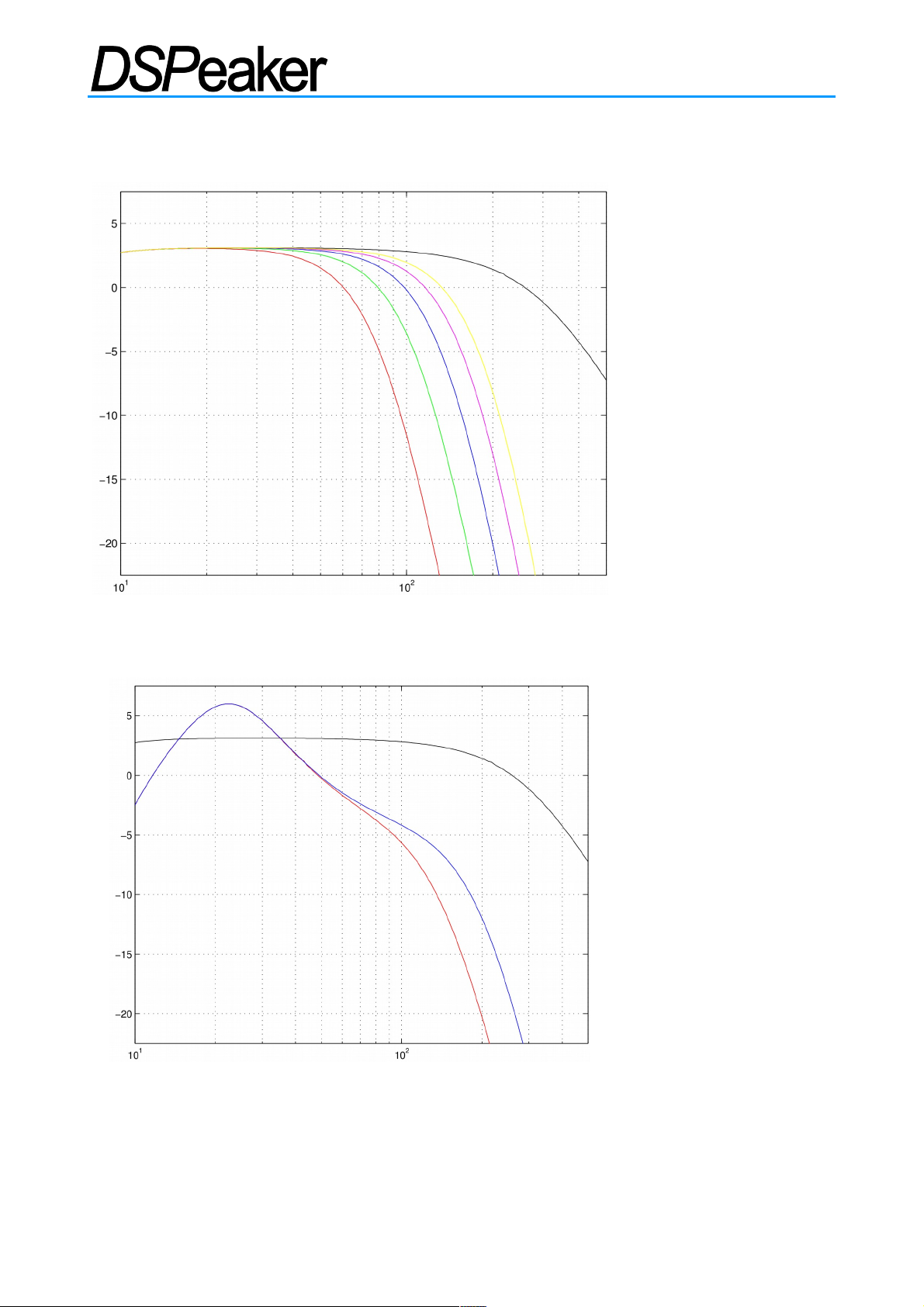
6.2. Low-pass Filter Responses (Anti-Mode 8033S-II)
Anti-Mode 8033S-II
low-pass
(from left to right)
Red: 60 Hz
Green: 80 Hz
Blue: 100 Hz
Magenta: 120 Hz
Yellow:140 Hz
Black: Neutral
The filters are 3rd order low-
pass with -3dB point at the
nominal frequency and with
18 dB / octave suppression.
6.3. Dipole Correction Responses (Anti-Mode 8033S-II)
Anti-Mode 8033S-II
dipole correction responses
(from right to left)
Black: Neutral
Blue: 200 Hz
Red: 140 Hz
Note: These are not target
or house curves.
The dipole correction acts
first to compensate the
natural 6dB / octave roll-off
of a dipole subwoofer. This
pre-adjusted response is
then measured and
straightened by the AntiModeTM algorithm.
Rev. 2.1 29.03.2019 Page 19 (20)
Page 20
ANTI-MODETM 8033 CINEMA / 8033S-II
7. Technical Specifications
Electrical characteristics:
Power consumption: 1.2 W
Input sensitivity: Line level (1.0 Vrms nominal, 1.75 Vrms max)
Amplification: 3.0 dB (bypass)
Operation voltage: 9 VAC or 12 VDC
Low-pass (analog): Bessel 12 dB / octave, Q ~ 0.5, fc = 250 Hz
8033 cinema 8033S-II
Frequency range (-3 dB): 5 – 160 Hz 5 – 250 Hz
Dynamic ratio: > 90 dB > 92dB
Firmware features:
Frequency resolution: < 0.5 Hz
Maximum attenuation: 96 dB
Filter Q-value range: Unlimited (32-bit integer space)
Sub-sonic filter: 10 Hz (user-selectable)
Computation accuracy: 32 / 40-bit integer
Latency: 2.7 ms
8033 cinema 8033S-II
Anti-Mode-Filters: 28 36
Correction range: 16 – 160 Hz 16 – 250Hz
Lift filters: 20Hz, 30Hz 20Hz, 25Hz, 30Hz
Lowpass filters: - 7 selectable modes
8. Manufacturer
VLSI Solution / DSPeaker Division
Hermiankatu 8
FIN-33720 Tampere
FINLAND
Tel: +358 50 462 3200
Email: [email protected]
9. Contact
Website: http://www.dspeaker.com/
Technical Support: [email protected]
Product Information: [email protected]
Rev. 2.1 29.03.2019 Page 20 (20)
 Loading...