

DSC WTK5504 User Manual
WTK5504 v1.0
Touchscreen User Manual [ENG]
Écran tactile manuel d'utilisation [FRA]
WARNING: This manual contains information on limitations regarding product use, function and
information on the limitation as to liability of the manufacturer. The entire manual should be carefully
read.

Read and save these instructions! Follow all warnings and instructions specified within this document and/or on the
equipment. Always ensure you obtain the latest version of the User Guide. Updated versions of this User Guide are
available by contacting your distributor.
Use these instructions in conjunction with the Installation Manual of the alarm panel with which this equipment is
intended to be used.
IMPORTANT SAFETY INSTRUCTIONS
To reduce the risk of fire, electric shock and/or injury, observe the following:
• Do not spill any type of liquid on the equipment.
• Do not attempt to service this product yourself. Opening or removing the cover may expose you to dangerous voltage or other risk. Refer servicing to qualified service personnel. Never open the device yourself.
• Do not touch the equipment and its connected cables during an electrical storm; there may be a risk of electric shock.
• Do not use the Alarm System to report a gas leak if the system is near a leak.
REGULAR MAINTENANCE AND TROUBLESHOOTING
Keep your WTK5504 Touchscreen keypad in optimal condition by following all the instructions that are included
within this manual and/or marked on the product.
HANDLING PRECAUTIONS
• Do not subject the touchscreen to mechanical shock (e.g., dropping or striking). Mechanical shock could damage the glass display.
• If the touchscreen glass is damaged, the liquid crystal fluid inside could leak out. Avoid contact with the liquid crystal fluid. If the liquid crystal fluid comes into contact with your skin or clothes, promptly wash it off using soap and
water.
• Do not apply excessive force to the display surface or adjoining areas. Excessive force will distort the image on the display.
• Do not use hard or sharp implements to operate the touchscreen. Operating the touchscreen with any implement harder than a finger could scratch the display.
• Do not attempt to disassemble the LCD Module.
CLEANING
• The WTK5504 features a cleaning mode that disables the Touchscreen for thirty seconds and prevents unintended button presses during cleaning. To enter cleaning mode press More > Functions > Clean Mode.
• If the display surface is contaminated, breathe on the surface and gently wipe it with a soft, dry cloth. If still not completely clean, moisten cloth with isopropyl alcohol.
• Clean the touchscreen with a soft cloth and isopropyl alcohol. Use of other cleaners such as water, ketone (e.g., acetone), and/or aromatic solvents (e.g., benzene and toluene) may damage the display. Do not use abrasives, water,
thinners, solvents or aerosol cleaners (spray polish), any aromatic solvents, ketones etc. that may enter through holes
in the WTK5504 Touchscreen keypad and cause damage.
TROUBLESHOOTING
Occasionally, you may have a problem with your system. If this happens, your Alarm Controller will identify the
problem and display an error message. Refer to the provided list when you see an error message on the display. If
additional help is required, contact your distributor for service.
WARNING: This equipment, the WTK5504 Touchscreen keypad, shall be installed and used within an environment that provides the pollution degree max 2 and over-voltages category II non-hazardous locations, indoor only. It
is designed to be installed, serviced and/or repaired by service persons only [service person is defined as a person
having the appropriate technical training and experience necessary to be aware of hazards to which that person may
be exposed in performing a task and of measures to minimize the risks to that person or other persons]. There are no
parts replaceable by the end-user within this equipment.
These safety instructions should not prevent you from contacting the distributor and/or the installer to obtain any
further clarification and/or answers to your concerns.
About Your Security System
Your DSC Security System has been designed to provide you with the greatest possible flexibility and convenience.
Read this manual carefully and have your installer instruct you on your system's operation and on which features
have been implemented in your system. All users of this system should be equally instructed in its use. Fill out the
“System Information” page with all of your zone information and access codes and store this manual in a safe place
for future reference.
NOTE: The PowerSeries, Alexor, and Impassa security systems include specific false alarm reduction features and
are classified in accordance with ANSI/SIA CP-01 Control Panel Standard - Features for False Alarm Reduction.
Please consult your installer for further information regarding the false alarm reduction features built into your sys
tem as all are not covered in this manual.
Carbon Monoxide Detection (must be enabled by your Installer)
This equipment is capable of monitoring carbon monoxide detectors and providing a warning if carbon monoxide is
detected. Please read the instructions that are available with the carbon monoxide detector.
Fire Detection (must be enabled by your Installer)
This equipment is capable of monitoring fire detection devices such as smoke detectors and providing a warning if
a fire condition is detected. Good fire detection depends on having adequate number of detectors placed in
appropriate locations. This equipment should be installed in accordance with NFPA 72 (N.F.P.A., Batterymarch
Park, Quincey MA 02269).
-
1

Testing
To ensure that your system continues to function as intended, you must test your system weekly. Please refer to the
“Testing your System” section in this manual. If your system does not function properly, call your installing
company for service.
Monitoring
This system is capable of transmitting alarms, troubles & emergency information to a central station. If you initiate
an alarm by mistake, immediately call the central station to prevent an unnecessary response.
NOTE: The monitoring function must be enabled by the installer before it becomes functional.
NOTE: There is a communicator delay of 30 seconds in this control panel. It can be removed, or it can be increased
up to 45 seconds, at the option of the end-user by consulting with the installer.
Maintenance
With normal use, the system requires minimum maintenance. Note the following points:
• Use the system test described in “Testing Your System” to check the battery condition. We recommend, however, that the standby batteries be replaced every 3-5 years.
• For other system devices such as smoke detectors, passive infrared, ultrasonic or microwave motion detectors or glassbreak detectors, consult the manufacturer’s literature for testing and maintenance instructions.
General System Operation
Your security system is made up of a DSC control panel, one or more keypads and various sensors and detectors.
The control panel will be mounted out of the way in a utility closet or in a basement. The control panel contains
system electronics and standby battery.
NOTE: Only the installer or service professional should have access to the control panel.
All the keypads have an audible indicator and command entry keys. The keypad is used to send commands to the
system and to display the current system status. The keypad(s) will be mounted in a convenient location inside the
protected premises close to the entry/exit door(s).
The security system has several zones of area protection and each of these zones will be connected to one or more
sensors (motion detectors, glass break detectors, door contacts, etc.). See Alarm Memory on page 13 for
information on sensors in alarm for this Touchscreen keypad.
Fire alarm verification is an available option on fire zones. When used, the system will begin an alarm transmission
sequence once the conditions for fire alarm verification are met. The fire alarm verification option is disabled by
default. Consult with your installer to enable fire alarm verification on your system.
A security system cannot prevent emergencies. It is only intended to alert you and, if included, your central station of
an emergency situation. Security systems are very reliable but they may not work under all conditions, and they are not
a substitute for prudent security practices or life and property insurance. Your security system should be installed and
serviced by qualified security professionals who should instruct you on the level of protection that has been provided
and on system operations.
Introduction
The WTK5504* two-way wireless touchscreen keypad is an interactive touch-sensitive color LCD that can be used
with the Alexor PC9155 and Impassa SCW9055/57 wireless panels. It can also be used with the PowerSeries alarm
panels in conjunction with a TR5164 transceiver module. The WTK5504P model is compatible with proximity (prox)
tags, which can be used to arm, disarm, and enter user functions (Alexor PC9155 and Impassa SCW9055/57 only).
IMPORTANT NOTICE
Due to the custom requirements of individual installations, some of the features described here may perform differ
ently than described. Refer to your Installation Instructions for the details of your specific installation and to this User
Manual for general security system information.
Specifications/Features
• Display. . . . . . . . . . . . . . . . . . . . . . . . . . . . . . . . . . . . . . 4.3" WVGA (800 480 pixel) color resistive touchscreen
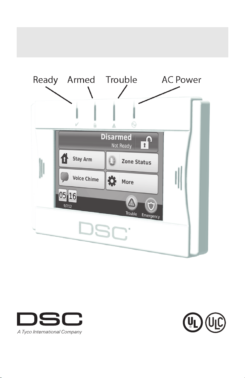
• LED indicators. . . . . . . . . . . . . . . . . . . . . . . . . . . . . . . . . . . . . . . . . . . . . . . . . . . . . 4 (Ready, Armed, Trouble, AC)
• “Night” light with adjustable brightness
• Dimensions (mounting). . . . . . . . . . . . . . . . . . . 5.5" x 3.6" x 1.0" [139.7 mm (L) x 91.4 mm (W) x 25.4 mm (D)]
• Horizontal viewing angle . . . . . . . . . . . . . . . . . . . . . . . . . . . . . . . . . . . . . . . . . . . . . . . . . . . . . . . . . . . . . 130° (typ.)
• Vertical viewing angle . . . . . . . . . . . . . . . . . . . . . . . . . . . . . . . . . . . . . . . . . . . . . . . . . 70° (top), 70° (bottom) (typ.)
• Brightness . . . . . . . . . . . . . . . . . . . . . . . . . . . . . . . . . . . . . . . . . . . . . . . . . . . . . . . . . . . . . . . . . . . . . . . . . 400 cd/m
• Operating environment . . . . . . . . . . . . . . . . . . . . . . . . . . . . . . . . . . . . . . . . . . . . . . . . .0°C to 49°C (32°F to 120°F)
• Operating frequency . . . . . . . . . . . . . . . . . . . . . . . . . . . . . . . . . . . . . . . . . . . . . . . . . . . . . . . . . . . . . . . . 433.92 MHz
• Relative humidity, non-condensing. . . . . . . . . . . . . . . . . . . . . . . . . . . . . . . . . . . . . . . . . . . . . . . . . . . . . .93% (max.)
• Display language(s) . . . . . . . . . . . . . . . . . . . . . . . . . . . . . . . . . . . . . . . . . . . . English, French, Spanish, Portuguese
*The models covered by this manual are WTK5504P-433 and WTK5504-433. The reference to WTK5504 throughout
this manual is representative for both model names unless it is identified differently.
-
2
2
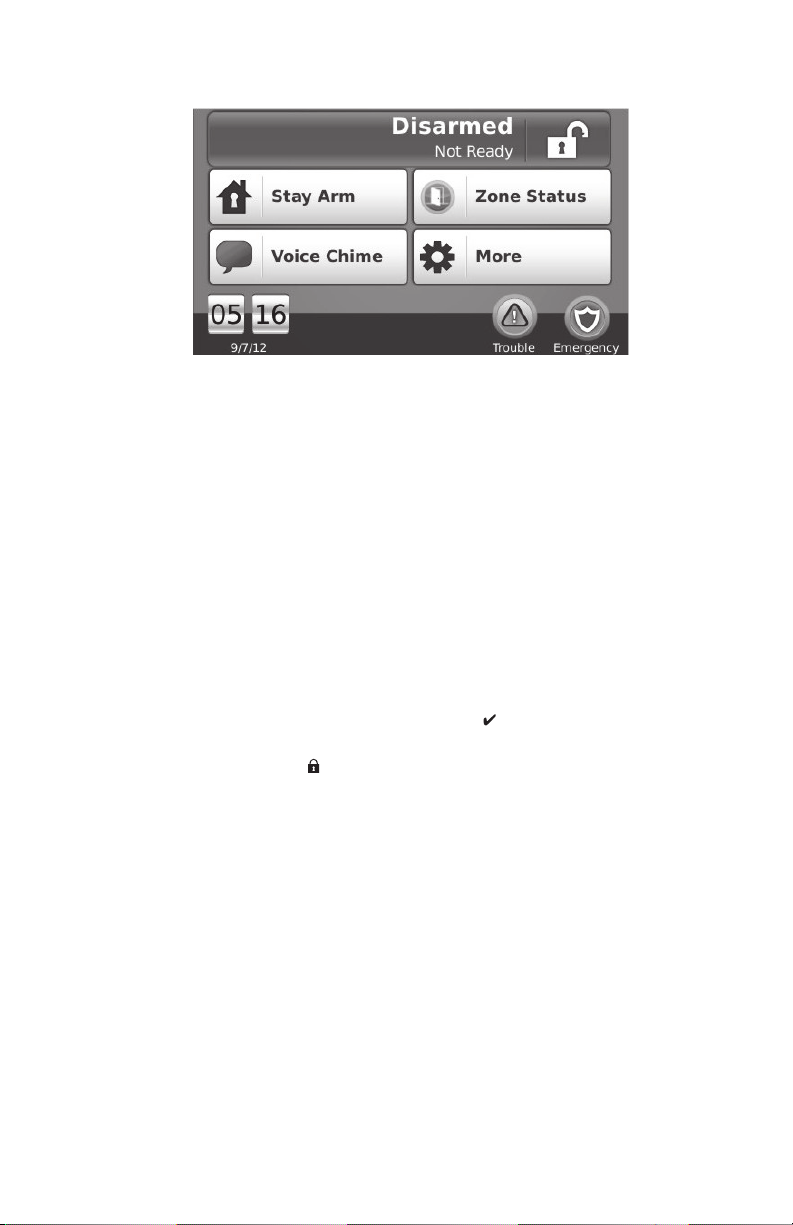
Home Screen
Figure 1 - Home Screen
System Status/Away Arm button - when disarmed, indicates that pressing will away arm the system; when
armed, indicates that pressing will disarm the panel.
Stay Arm button - indicates your arming option alternative to the one in the System Status message bar.
Zone Status button - show
Voice Chime button - select
chime, audible chime or disabled. (This does not affect the system chime status.)
More button - al
Time/date and tempe
installed.
Trouble/alarm in memory - onl
Emergency button - takes y
s open zones or zones in alarm.
s whether the chime will be heard on the keypad, and whether it will be verbal
lows you to select Functions, Installer Options, or User Options.
rature - displays time/date; temperature is displayed if a WT4911 outdoor siren is
y displayed when these conditions are present.
ou to the screen to choose from Fire, Auxiliary and Panic keys.
Arming and Disarming the System
See also Night Arming (Alexor PC9155 and Impassa SCW9055/57 only) on page 6 and No-Entry Arming on page 7.
Stay Arm (Arming the Perimeter)
Home > Stay Arm
Ask your alarm company if this function is available on your system.
Stay arming bypasses the interior protection (i.e., motion senso
windows).
1. Close all sensors (i.e., stop motion and close doors). The Ready (
2. Press the Stay Arm button (and enter your Access Code) and do not leave the premises.
• The verbal prompt announces “User Arming in Progr
• During exit delay, the Armed (
The display indicates “Exit Delay in Progress
allows an individual to leave the premises while arming the system for those still on the premises. When the
exit delay expires, a verbal prompt announces “System Armed Stay”, the Ready LED turns off, the Armed
LED remains on and the keypad stops sounding to indicate that the alarm system is armed.
or SIA FAR listed panels, the Stay Arming exit delay will be twice as long as the Away Arming exit delay.
NOTE: F
) and Ready indicators turn on to visually indicate that the system is arming.
Silent Exit Delay
If the system is armed using the Stay Arm button or using the “No-Entry” Arming method (see page 7), the audible
progress annunciation (keypad buzzer)
only).
NOTE: For no
n CP-01 versions, Standard exit time is used.
is silenced and the exit time doubled for that exit period only (CP-01 versions
Disarm
Home > Disarm
To disarm the system
When Disarm is selected from the Home screen, or an entr
Access Code in the keypad. If an invalid code is entered, “invalid code” will appear on the screen and an error tone will
sound. Re-enter the correct code.
• The system returns to the Home screen and t
• The alarm status is momentarily displ
disarmed”.
• The green Ready indicator turns ON.
rs) and arms the perimeter of the system (i.e., doors and
) indicator should be on.
ess”. An exit delay period follows.
,” and the pre-programmed exit delay begins. The exit delay
y delay begins, a numerical keypad is displayed. Enter your
he red Armed indicator turns OFF.
ayed in the status bar and the voice prompt announces “System
3
Away Arm
Home > Away Arm
When Away Arm is selected from the Home screen:
• “Exit delay in progress” is displayed in the Status B
• The voice prompt announces “User
• The touchscreen “beeps” at a 1-second interval during the exit delay, then double-beeps for the last 10
seconds.
If Disarm is selected during the exit delay:
• A numeric keypad is displayed. T
• The Arming sequence is aborted and the syste
• The Armed LED turns OFF.
At the end of the pre-progr
• The Home screen is displayed, indicat
• The voice prompt announces “System Armed Away”.
• The Ready Indicator turns OFF.
• “Away Armed” is displayed in the Status Bar.
ammed exit delay:
arming in progress”.
ap your access code.
ing that the system is armed.
ar. The pre-programmed exit delay begins.
m returns to the Home screen.
Bell/Siren Sounds After Away Arming
Audible Exit Fault
In an attempt to reduce false alarms, the Audible Exit Fault is designed to notify you of an improper exit when arming
the system in the Away mode. In the event that you fail to exit the premises during the allotted exit delay period, or if
you do not securely close the Exit/Entry door, the system will notify you that it was improperly armed in two ways: the
keypad will emit one continuous beep and the bell or siren will sound.
Your installer will tell you if this feature has been enab
1. Re-enter the premises.
2. Enter your access code to disarm the system. You must
3. Follow the Away arming procedure again, making sure to close the entry/exit door properly.
led on your system. If this occurs:
do this before the entry delay timer expires.
Arming Error
An error tone will sound if the system is unable to arm and the voice prompt will state “Failed to arm”. This will happen if the system is not ready to arm (i.e., sensors are open)
prompt will then state “check open zones and troubles.” If this happens, ensure all sensors are secure. Try again, ensuring that a valid access code is entered. Pl
means.
ease check with your installer to determine if arming is inhibited by any other
or if an incorrect user code has been entered. A voice
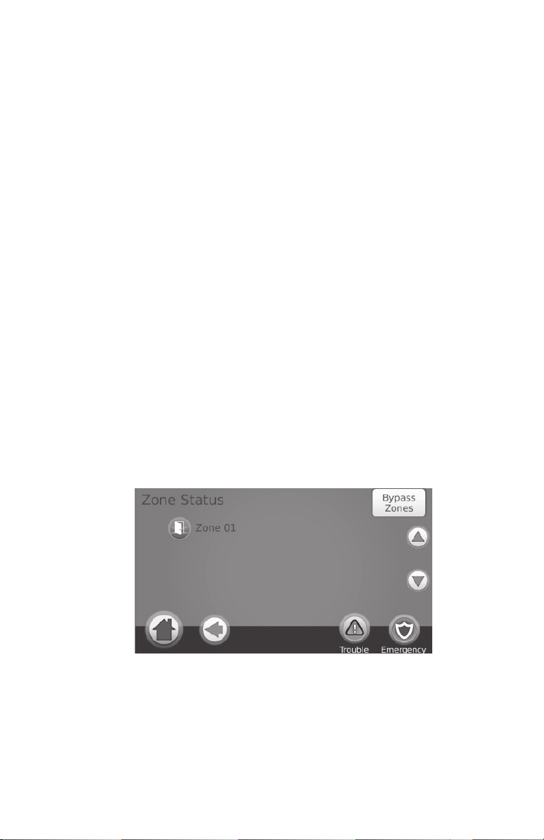
Zone Status
Home > Zone Status
This screen allows you to view the status of the zones on the system. From the Home screen, press Zone Status to go to
the list of zones, which is displayed from Zone 1 to Zone 64. You will see any zones that are either open or in alarm.
Figure 2 - Zone Status
Bypassed Zones
Use the zone bypass feature when a zone is open but the system needs to be armed. Bypassed zones will not cause an
alarm when opened. Bypassing zones reduces the level of security. If you are bypassing a zone because it is not functioning, call a service technician immediately so that the problem can be resol
working order.
Ensure that no zones are unintentionally bypassed when armi
while the system is disarmed. Bypassed zones are automatically cancelled each time the system is disarmed and must
be bypassed again, if required, before the next arming.
NOTE: 24
NOTE: Fo
bypassed. (e.g., smoke detectors).
-hour zones can only be unbypassed manually.
r security reasons, your installer has programmed the system to prevent certain zones from being
ng your system. Zone bypassing can only be performed
ved and your system returned to proper
4
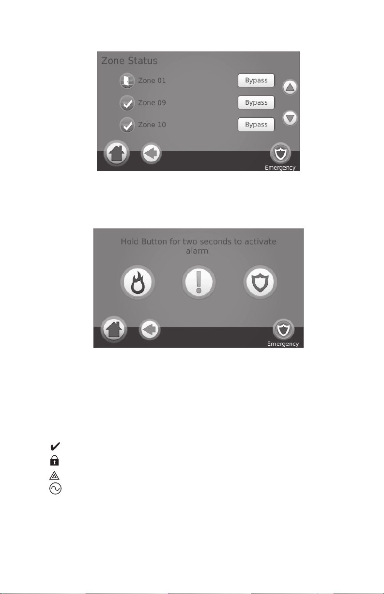
Figure 3 - Zone Bypass
Bypassing Zones with a WTK5504
Home > Zone Status > Bypass Zones
Press Bypass Zones, scroll up/down through the desired zones, and tap on the bypass icon to bypass the zone. To unbypass a zone, tap the unbypass icon.
Emergency Key
When the emergency key is pressed, a new page will appear with:
Fire
Auxiliary Other
Panic Po
IMPORTANT NOTE: The emergency keys are on by default. Please ask your installer if the Fire,
Auxiliary and Panic keys are enabled.
NOTE: Auxiliary alarm key is not intended to be used for medical signals.
NOTE: The
Fire assistance required. Press and hold for 2 seconds to activate.
assistance required. Press and hold for 2 seconds to activate.
lice assistance required. Press and hold for 2 seconds to activate.
se events are recorded in the event buffer.
Figure 4 - Emergency Screen
Indicators
Ready - lit when the system/partition is ready to be armed.
Armed - lit when the system/partition is armed.
Trouble - lit when there is a trouble on the system; flashes when battery is low.
AC Power - lit when power is present; off when power is absent.
5
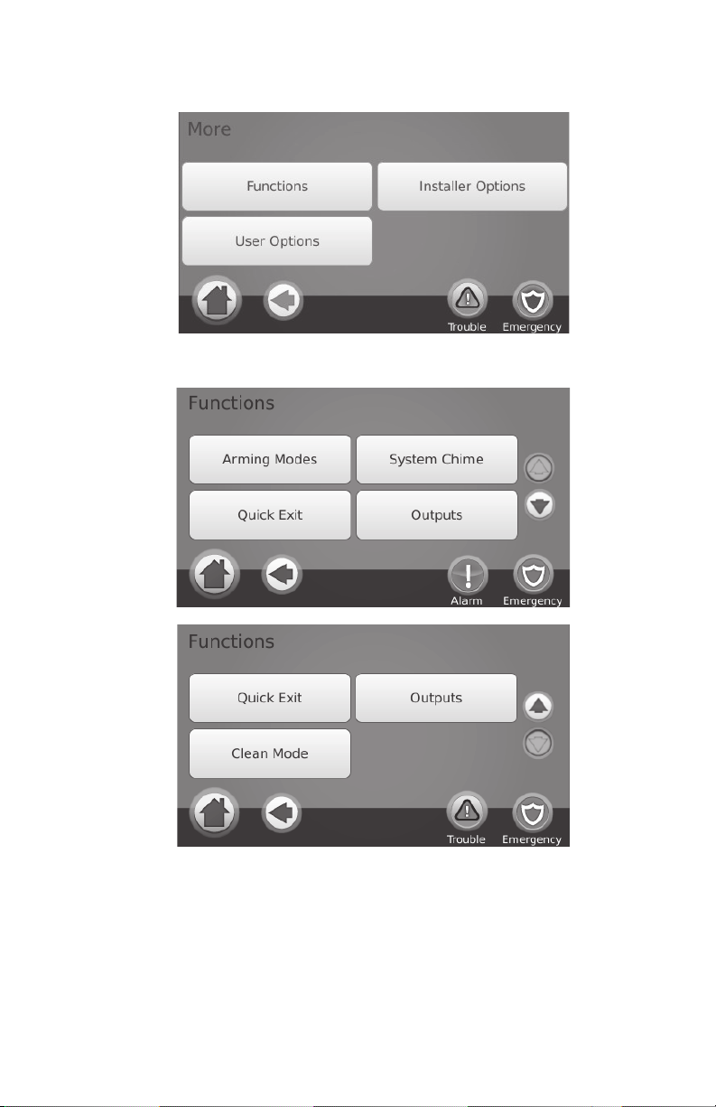
More Screen
Home > More
More Functions Screens
Home > More > Functions
Figure 5 - More Screen
Figure 6 - More Functions Screen
Figure 7 - More Functions Screen
Arming Modes
From the Arming Modes screen, you have the option to Night Arm, No-Entry Arm, or Instant Stay arm.
Night Arming (Alexor PC9155 and Impassa SCW9055/57 only)
Home > More > Functions > Arming Modes > Night Arm
Night Arming restricts movement to certain interior zones (e.g. hallways from bedrooms to bathroom). It arms all interior zones except for zones programmed as Night zones.
To fully arm the system when it has been ar
“Night arming in progress”. Night zones are only armed in Away mode, which permits limited movement within the
premises when the system is fully armed. Ensure that your installer has provided you with a list identifying zones
programmed as night zones.
med in Stay mode, press Night Arm. The voice prompt will announce
6
No-Entry Arming
Home > More > Functions > Arming Modes > No Entry
This allows the system to be armed without an entry delay from zones that normally have one. An entry through any
zone will therefore create an instant alarm. To arm without an entry delay:
1. Check that the Ready indicator is on.
2. From the Home screen, press No Entry
“Arming with No-entry delay” appears on the screen. The system is now armed in Stay mode.
. The verbal prompt announces “No-entry arming in progress” and
Silent Exit Delay
If the system is armed using the Stay Arm button or using the “No-Entry” Arming method, the audible progress annunciation (keypad buzzer) is silenced and t
NOTE: For no
n CP-01 versions, Standard exit time is used.
he exit time doubled for that exit period only (CP-01 versions only).
Instant Stay Arming (for Impassa SCW9055/57 and Alexor PC9155)
Home > More > Functions > Arming Modes > Instant Stay Arming
Where programmed by the installer, this function key, when held down for 2 seconds, allows you to arm the system in
Stay mode instantly. No beeps will sound and there will be no exit delay.
NOTE: Th
is is not enabled on CP-01 listed systems.
System Chime (Chime Enable/Disable)
Home > More > Functions > System Chime
Press the key to choose the setting opposite to the one currently in use. A brief message of either “Door Chime
Enabled” or “Door Chime Disabled” will appear to indicate the current setting. When chime is enabled, you can use
the Voice Chime button on the Home screen to select Voice Chime, Chime, or No Chime.
Quick Exit
Home > More > Functions > Quick Exit
If the system is armed and you need to exit, use the quick exit function to avoid disarming and rearming the system. To
activate this function, press Quick Exit. The “Quick Exit in Progress” screen appears and the voice prompt says,
“Quick exit in progress” followed by “Please exit now”. You have 2 minutes to leave the premises through your exit
door. When the door is closed again the remaining exit time is cancelled.
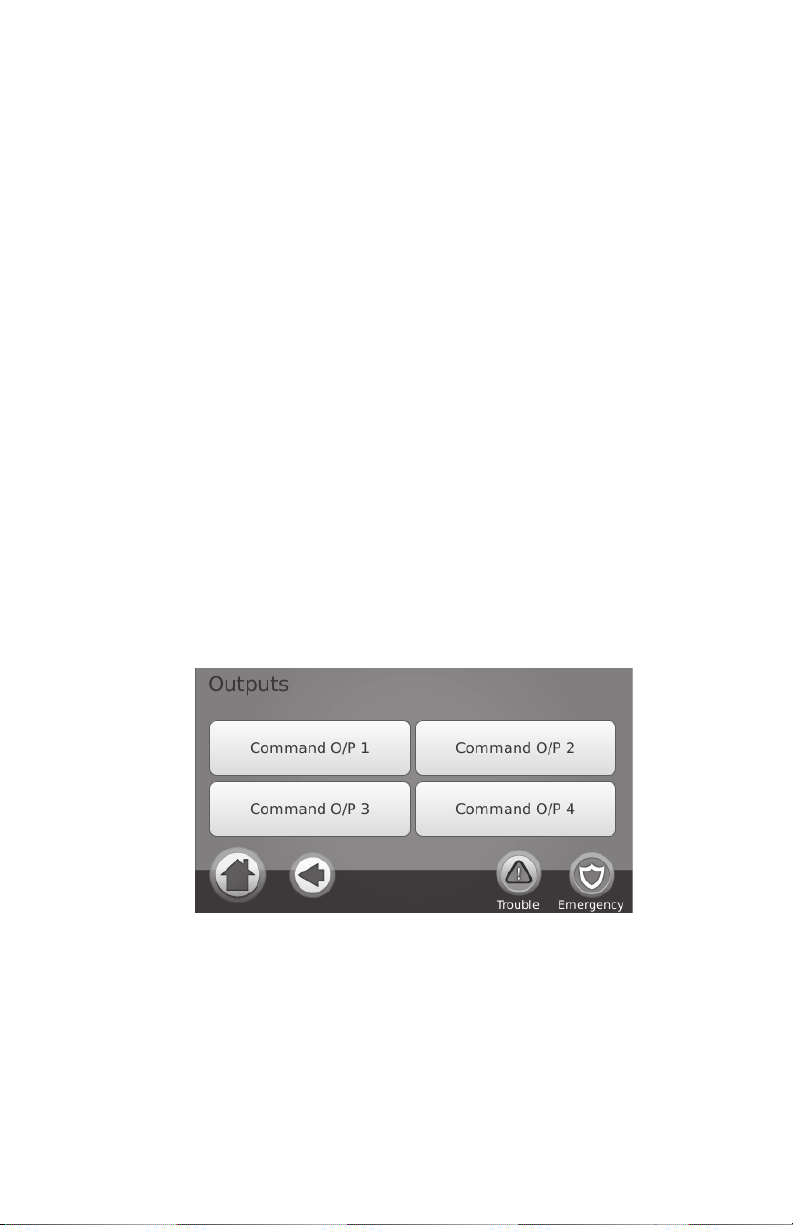
Outputs
Home > More > Functions > Outputs
Your installer may have programmed these keys to perform other functions (reset sensors after an alarm, open your
garage door etc.) To activate these functions, press the appropriate option. See also Sensor Reset on page 13.
Figure 8 - Outputs
Clean Mode
Home > More > Functions > Clean Mode
Clean Mode allows the user to touch (i.e., clean) the screen without enabling or disabling any functions. The screen
will remain in this mode for 30 seconds, then return to the More Functions screen.
7
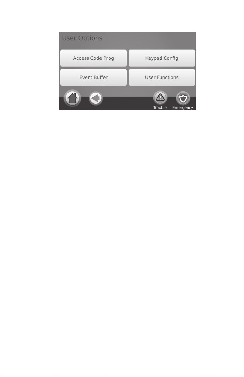
User Options
Figure 9 - User Options
Access Codes
Home > More > User Options > Access Code Prog [Master Code]
When Access Code Programming is selected from the User Options menu, the keypad prompts for a Master Code.
When a valid Master Code is entered, a numeric keypad is displayed with arrows to scroll to the desired user to add/
edit. Press the select button to enter the user options or enter the 2-digit user number to jump directly to a user.
Set Access Code – adds/edits the 4 or 6-digit
Prox Tag Programming – enrolls proximity tags (only available on WTK5504P).
User Options – enables/disables different options for the user.
Delete User – deletes the user from the system.
The access codes have programmabl
ESCORT5580TC or one-time use activation.
Master Code (Access Code 40) - The master code, if pr
NOTE: Th
Supervisor Codes - These codes can be used to program
programmed, the supervisor codes receive the master code’s attributes. These attributes are changeable. Any user code
can be made a supervisor code by enabling User Code Attribute 1 (please see below for details).
Duress Codes - Duress codes are standard user codes t
when they are entered to perform any function on the system. Any user code can be made a duress code by enabling
User Code Attribute 2 (please see below for details).
NOTE: Du
NOTE: Access
duplicate code is entered. If a duplicate code is found, an error tone is given and the code is returned to what it was
before it was changed. This applies to both 4 and 6-digit codes.
e master code’s attributes cannot be changed.
ress codes are not valid when entering User Options, Master Functions or Installer’s sections.
codes cannot be programmed as a duplicate or as a “Code +/- 1”. The keypad will notify you if a
code.
e attributes which allow zone bypassing, remote access using the
ogrammed, can only be changed by the installer.
additional codes which have equal or lesser attributes. Once
hat transmit the Duress Reporting Code to the central station
User Code Attributes
1. The default attributes of a new code will be the attributes of the code used to enter User Programming whether it is a new code or an existing code being programmed.
2. System Master Code 40 has att
NOTE: The
se attributes are not changeable.
ributes 3-4 ON by default.
Inherent Attributes (all codes except installer and maintenance)
Arm/Disarm - Any access code will be valid for arming and disarming that partition.
Command Outputs - If these outputs require access
mand output functions.
code entry, any Access Code will be valid for performing com-
Programmable Attributes
1. Supervisor Code 4. Remote Access
2. Duress Code 5. Bell Squawk upon Arming/Disarming
3. Zone Bypassing Enabled 6. One Time Use Code
Bell Squawk Attribute
This attribute is used to determine whether an access code should generate an arming/disarming Bell Squawk upon
entry of the code for Away arming. The wireless keys with access codes associated with them may generate Arming/
Disarming Bell squawks. If desired, this option may be used with codes that are manually entered. Please contact your
installer to have this programmed.
NOTE: Th
NOTE: This
assigned to a wireless key is manually entered at a keypad.
e Master Code cannot use the Bell Squawk attribute, but is required to enable it for other codes.
feature cannot prevent the Arming/Disarming squawks from being generated if an access code
8
Setting an Access Code
1. Select “Set Access Code”. A keypad screen is shown with the existing code. If there is no existing code, “AAAA” (or AAAAAA for 6 digits) is shown.
2. Start to enter a new code. The code area will be cleared,
pressed, the new code will be cleared, but the old code is not deleted by this action. Once the last digit is
entered the new code will have replaced the old code; no further action is required to save the code. If the
screen “times out” (goes grey or black) or you exit the screen without completing the new code, the previous
code will remain.
and the new code will be shown. If the clear key is
Proximity (Prox) Tag Enrollment and Use (WTK5504P keypad only)
Home > More > User Options > Access Code Prog [Master Code] > Select
User > User xx settings > Prox Tag Prog
Enrolling Proximity Tags
1. Press Prox Tag Programming.
2. Place the prox tag near the tag reader
“Tag Enrolled Successfully” will be displ
previously, an error tone will sound. The screen will read “Duplicate Tag/User Code”.
NOTE: Prox t
ags do not work on PowerSeries panels.
at the top of the keypad to assign it to the user code. The message
ayed and the keypad will beep. If the proximity tag has been enrolled
Erasing Prox Tags
Delete tags from the system when they are lost or no longer needed. To delete a proximity tag, the user code it is associated with must be deleted.
1. Press More > User Options > Access Cod
2. Use left and right arrow buttons to select the user number as
press Select.
3. Press Delete User and confirm by pressing Yes.
e Prog. [Master Code].
sociated with the proximity tag to be deleted and
Replacing Existing Prox Tags
To keep the same user code and number, but enroll a new tag due to loss of the old one
1. Press Prox Tag Programming.
2. Confirm that you want to overwrite the existing tag by pressing Yes.
3. Place the prox tag near the tag reader
will be displayed and the keypad will beep.
at the top of the keypad. The message “Tag Enrolled Successfully”
User Options
Erasing an Access Code
To erase a code, select the code and choose Delete User. The system will delete the code immediately and the user will
be returned to select another code.
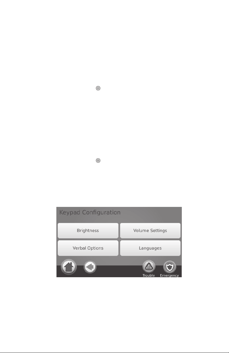
Keypad Configuration
Figure 10 - Keypad Configuration
Changing Brightness
Home > More > User Options > Keypad Config > Brightness
Use the slide bar to adjust brightness to the desired setting. To exit, press the Back or Home button.
Night Light Brightness Control
Home > More > User Options > Keypad Config > Brightness > Nightlight
You can use the slide bar to determine the brightness of the keypad “night light” that shines from the sides of the keypad. When this slider is in the position of darkest (left hand side of the slider)
the slider is all the way to the right, then the night light will be on as bright as possible.
1. Use the slide bar to select the desired brightness of the night light backlighting.
2. To exit press the Back or Home button.
9
, the night light feature will be disabled. If

Setting Screen Saver Time-out
Home > More > User Options > Keypad Config > Brightness > Screen off
after X:XX:XX
You can use the slide bar to determine how long until the screen saver activates after the last button press. The screen
saver will either show the date and time or show a black screen, depending on how your installer configured the key
pad. Valid values for this option are between 10 seconds and 10 minutes in 10 second steps. When this slider is in the
far left position, the screen saver is disabled and the screen will remain on.
1. Use the slide bar to select the desired duration for the screen to remain active.
2. To exit press the Back or Home button.
Verbal Prompts
Home > More > User Options > Keypad Config > Verbal Options
1. A button toggles verbal options prompts on and off. When Verbal Chime is set to on, the WTK5504 will speak
the zone label words (e.g., ‘Laundry Room Window’) when the zone chimes. When Verbal Prompt is set to on,
the WTK5504 will speak system prompts (e.g., ‘Quick Exit in progress’).
2. To exit press the Back or Home button.
Adjusting the Keypad Tone
Home > More > User Options > Keypad Config > Volume Setting > Tone Control
This allows you to select different tones of the keypad beeps. Use the slide bar to adjust the tone to the desired setting.
Changing the Buzzer Volume
Home > More > User Options > Keypad Config > Volume Setting > Volume
Use the slide bar to adjust buzzer volume to the desired setting.
Changing the Voice Volume
Home > More > User Options > Keypad Config > Volume Setting > Voice
Volume
When this option is selected the keypad allows you to scroll through 4 different speaker volume levels.
At each volume level, the keypad will say “test”. The right side is the default setting, which is the maximum volume.
The left side is the lowest volume, but does not turn the speaker off. Use the slide bar to adjust the volume to the
desired level.
NOTE: For UL/ULC installations, the level of the buzzer shall not be changed from the default level.
Changing Language
Home > More > User Options > Keypad Config > Languages
1. Select the desired language.
2. To exit press the Back or Home button.
Event Buffer
Home > More > User Options > Event Buffer [Master Code]
Your panel keeps a record of events that have occurred on the system, such as when a zone is bypassed, an alarm
occurs or a zone is violated. The event buffer (log) displays the date, time and the full description of the event(s),
including zone/user label. The log is organized from the most recent event (top) to past events (down). The left arrow
scrolls forward in time. The right arrow scrolls back in time. The Back returns you to the Home screen. This screen
will time out to the Home screen after 30 seconds of inactivity.
User Functions
Home > More > User Options > User Functions [Master Code]
The user functions menu can only be accessed when the system is disarmed. Only the master code or a user code with
the supervisor attribute enabled may be used to access this mode. From this screen you can access the following
options:
• Time and Date
• System Test
• Late to Open Programming
• Late to Open - On/Off
• Auto-Arm Programming
• Auto-Arm On/Off
• Enable DLS
• User Call-Up
•User Walk Test
Time & Date Programming
Home > More > User Options > User Functions [Master Code] > Time and
Date
1. To change the time/date press Time and Date. Tap on the section you would like to change and use the up/ down arrows to change time/date.
2. To exit press the Back or Home button.
-
10

System Test
NOTE: If you are going to perform a System Test, call your Monitoring Station to inform them when you begin and
also when you end the test.
All smoke detectors in this installation must be tested by your smoke detector installer or dealer once a year to ensure
they are functioning correctly. It is the user’s responsibility to test the system weekly (excluding smoke detectors).
NOTE: Should the system fail to function properly, call your installation company for service immediately.
Testing Your Keypad Sounder and Siren
Home > More > User Options > User Functions [Master Code] > System Test
The System Test performs a two-second check of the keypad sounder and bell or siren, in addition to testing the keypad status lights and the panel backup battery.
1. After pressing System Test, the keypad and system buzzer will sound an error tone for 2 seconds. After the
buzzer stops sounding, the keypad will say “Test” at full volume, regardless of whether verbal chime or
prompting are enabled and regardless of the volume setting. The keypad LEDs will all flash for the 2-second
duration and a progress wheel will be shown on the screen. This test also forces the panel to perform a battery
check, and it sends a test transmission signal to the monitoring station.
2. To exit the function menu, press the Back button.
Testing Your Entire System (User Walk Test)
Home > More > User Options > User Functions [Master Code] > User Walk
Test
1. Prior to testing, ensure that the system is disarmed and the Ready light is on.
2. Close all zones to return the system to the Ready state.
3. Perform a System Test by following the steps in the “Testing Your Keypad Sounder and Siren” section.
4. Test the zones by activating each detector in turn (e.g., open each door/window or walk in motion detector areas).
On a WTK5504 keypad, the following messages will be displayed when each zone (detector) is activated: “Ready to
Force,” or “Not Ready”. Use the zone status button to view which zones are open. The message will disappear when
the zones are closed.
NOTE: Some features described above will not be functional unless enabled by your installer. Ask your installer
which features are functional on your system.
Late-to-Open Programming
Home > More > User Options > User Functions [Master Code] > Late to Open
Programming
The late-to-open control notifies you, and sends a message to the monitoring station, when the alarm system is not disarmed by the programmed time of day. When this button is pressed, you can program the late-to-open time of day for
each day of the week, Sunday through Saturday. You can then program the desired late-to-open time. An entry of all 9s
means the time is disabled for that day.
NOTE: This feature does not exist on PowerSeries panels, and attempts to program will return with “Function Not
Available” along with an error tone.
Late-to-Open On/Off
Home > More > User Options > User Functions [Master Code] > Late to
Open On/Off
When this button is pressed and the late-to-close feature is currently disabled, “Late to Open Enabled” is displayed on
the keypad and acknowledgment beeps sound. If the button is pressed and the late to close feature is enabled, “Late to
Open Disabled” is displayed on the keypad and an error tone sounds.
NOTE: This feature does not exist on a PowerSeries panel, and so if the button is pressed it will return with
“Function Not Available” and sound an error tone.
Auto-Arm Programming
Home > More > User Options > User Functions [Master Code] > Auto-Arm
Programming
The system can be programmed to arm at a programmed time each day. Upon entry of this section, enter the desired
Auto-Arm time for each day of the week.
At the selected Auto-Arm time, the keypad buzzers will sound for a programmed amount of time (programmable by
the installer only) to warn that an auto-arm is in progress. The bell can also be programmed to squawk once every 10
seconds during this warning period. When the warning period is complete, the system will arm with no exit delay and
in the Away Mode.
Auto-Arming can be cancelled or postponed by entering a valid access code only during the programmed warning
period. Auto-Arming will be attempted at the next programmed time. When the Auto-Arming process is cancelled or
postponed, the Auto-arm Cancellation Reporting Code will be transmitted (if programmed).
If arming is inhibited by one of the following, the Auto-Arm Cancellation transmission will be communicated:
• AC / DC Inhibit Arm
• Latching System Tampers
• Zone Expander Supervisory Fault
11
 Loading...